Embed Size (px)
Citation preview

E2A Cylindrical Proximity Sensor 1
Cylindrical Proximity Sensor
E2ASafe Mounting with Greater Sensing Distance• Ensures a sensing distance approximately 1.5 to 2
times larger than that of any conventional OMRON Sensor.
• Problems such as the collision of workpieces are eliminated.
• Full range of standard sizes (M8, M12, M18 and M30; both long and short barrels)
• Modular construction simplifies customization.
Ordering InformationSize Sensing
distanceConnection Body
materialThread length (overall length)
Output configuration
Operation mode NO Operation mode NC
M8 Shielded 2.0 mm Pre-wired Stainless steel
27 (40) PNP E2A-S08KS02-WP-B1 2M E2A-S08KS02-WP-B2 2M
NPN E2A-S08KS02-WP-C1 2M E2A-S08KS02-WP-C2 2M
49 (62) PNP E2A-S08LS02-WP-B1 2M E2A-S08LS02-WP-B2 2M
NPN E2A-S08LS02-WP-C1 2M E2A-S08LS02-WP-C2 2M
M12 connector Stainless steel
27 (43) PNP E2A-S08KS02-M1-B1 E2A-S08KS02-M1-B2
NPN E2A-S08KS02-M1-C1 E2A-S08KS02-M1-C2
49 (65) PNP E2A-S08LS02-M1-B1 E2A-S08LS02-M1-B2
NPN E2A-S08LS02-M1-C1 E2A-S08LS02-M1-C2
Brass 27 (43) PNP E2A-M08KS02-M1-B1 E2A-M08KS02-M1-B2
NPN E2A-M08KS02-M1-C1 E2A-M08KS02-M1-C2
49 (65) PNP E2A-M08LS02-M1-B1 E2A-M08LS02-M1-B2
NPN E2A-M08LS02-M1-C1 E2A-M08LS02-M1-C2
M8 connector (3-pin)
Stainless steel
27 (39) PNP E2A-S08KS02-M5-B1 E2A-S08KS02-M5-B2
NPN E2A-S08KS02-M5-C1 E2A-S08KS02-M5-C2
49 (61) PNP E2A-S08LS02-M5-B1 E2A-S08LS02-M5-B2
NPN E2A-S08LS02-M5-C1 E2A-S08LS02-M5-C2
Non-shielded 4.0 mm Pre-wired Stainless steel
27 (40) PNP E2A-S08KN04-WP-B1 2M E2A-S08KN04-WP-B2 2M
NPN E2A-S08KN04-WP-C1 2M E2A-S08KN04-WP-C2 2M
49 (62) PNP E2A-S08LN04-WP-B1 2M E2A-S08LN04-WP-B2 2M
NPN E2A-S08LN04-WP-C1 2M E2A-S08LN04-WP-C2 2M
M12 connector Stainless steel
27 (43) PNP E2A-S08KN04-M1-B1 E2A-S08KN04-M1-B2
NPN E2A-S08KN04-M1-C1 E2A-S08KN04-M1-C2
49 (65) PNP E2A-S08LN04-M1-B1 E2A-S08LN04-M1-B2
NPN E2A-S08LN04-M1-C1 E2A-S08LN04-M1-C2
Brass 27 (43) PNP E2A-M08KN04-M1-B1 E2A-M08KN04-M1-B2
NPN E2A-M08KN04-M1-C1 E2A-M08KN04-M1-C2
49 (65) PNP E2A-M08LN04-M1-B1 E2A-M08LN04-M1-B2
NPN E2A-M08LN04-M1-C1 E2A-M08LN04-M1-C2
M8 connector (3-pin)
Stainless steel
27 (39) PNP E2A-S08KN04-M5-B1 E2A-S08KN04-M5-B2
NPN E2A-S08KN04-M5-C1 E2A-S08KN04-M5-C2
49 (61) PNP E2A-S08LN04-M5-B1 E2A-S08LN04-M5-B2
NPN E2A-S08LN04-M5-C1 E2A-S08LN04-M5-C2

2 E2A Cylindrical Proximity Sensor
Note: M30 non-shielded Models with double sensing distance and short barrels cannot be mounted due to the necessary separation distance fromthe surrounding metal. Standard sensing models are thus available.
M12 Shielded 4.0 mm Pre-wired Brass 34 (50) PNP E2A-M12KS04-WP-B1 2M E2A-M12KS04-WP-B2 2M
NPN E2A-M12KS04-WP-C1 2M E2A-M12KS04-WP-C2 2M
56 (72) PNP E2A-M12LS04-WP-B1 2M E2A-M12LS04-WP-B2 2M
NPN E2A-M12LS04-WP-C1 2M E2A-M12LS04-WP-C2 2M
M12 connector Brass 34 (48) PNP E2A-M12KS04-M1-B1 E2A-M12KS04-M1-B2
NPN E2A-M12KS04-M1-C1 E2A-M12KS04-M1-C2
56 (70) PNP E2A-M12LS04-M1-B1 E2A-M12LS04-M1-B2
NPN E2A-M12LS04-M1-C1 E2A-M12LS04-M1-C2
Non-shielded 8.0 mm Pre-wired Brass 34 (50) PNP E2A-M12KN08-WP-B1 2M E2A-M12KN08-WP-B2 2M
NPN E2A-M12KN08-WP-C1 2M E2A-M12KN08-WP-C2 2M
56 (72) PNP E2A-M12LN08-WP-B1 2M E2A-M12LN08-WP-B2 2M
NPN E2A-M12LN08-WP-C1 2M E2A-M12LN08-WP-C2 2M
M12 connector Brass 34 (48) PNP E2A-M12KN08-M1-B1 E2A-M12KN08-M1-B2
NPN E2A-M12KN08-M1-C1 E2A-M12KN08-M1-C2
56 (70) PNP E2A-M12LN08-M1-B1 E2A-M12LN08-M1-B2
NPN E2A-M12LN08-M1-C1 E2A-M12LN08-M1-C2
M18 Shielded 8.0 mm Pre-wired Brass 39 (59) PNP E2A-M18KS08-WP-B1 2M E2A-M18KS08-WP-B2 2M
NPN E2A-M18KS08-WP-C1 2M E2A-M18KS08-WP-C2 2M
61 (81) PNP E2A-M18LS08-WP-B1 2M E2A-M18LS08-WP-B2 2M
NPN E2A-M18LS08-WP-C1 2M E2A-M18LS08-WP-C2 2M
M12 connector Brass 39 (53) PNP E2A-M18KS08-M1-B1 E2A-M18KS08-M1-B2
NPN E2A-M18KS08-M1-C1 E2A-M18KS08-M1-C2
61 (75) PNP E2A-M18LS08-M1-B1 E2A-M18LS08-M1-B2
NPN E2A-M18LS08-M1-C1 E2A-M18LS08-M1-C2
Non-shielded 16.0 mm Pre-wired Brass 39 (59) PNP E2A-M18KN16-WP-B1 2M E2A-M18KN16-WP-B2 2M
NPN E2A-M18KN16-WP-C1 2M E2A-M18KN16-WP-C2 2M
61 (81) PNP E2A-M18LN16-WP-B1 2M E2A-M18LN16-WP-B2 2M
NPN E2A-M18LN16-WP-C1 2M E2A-M18LN16-WP-C2 2M
M12 connector Brass 39 (53) PNP E2A-M18KN16-M1-B1 E2A-M18KN16-M1-B2
NPN E2A-M18KN16-M1-C1 E2A-M18KN16-M1-C2
61 (75) PNP E2A-M18LN16-M1-B1 E2A-M18LN16-M1-B2
NPN E2A-M18LN16-M1-C1 E2A-M18LN16-M1-C2
M30 Shielded 15.0 mm Pre-wired Brass 44 (64) PNP E2A-M30KS15-WP-B1 2M E2A-M30KS15-WP-B2 2M
NPN E2A-M30KS15-WP-C1 2M E2A-M30KS15-WP-C2 2M
66 (86) PNP E2A-M30LS15-WP-B1 2M E2A-M30LS15-WP-B2 2M
NPN E2A-M30LS15-WP-C1 2M E2A-M30LS15-WP-C2 2M
M12 connector Brass 44 (58) PNP E2A-M30KS15-M1-B1 E2A-M30KS15-M1-B2
NPN E2A-M30KS15-M1-C1 E2A-M30KS15-M1-C2
66 (80) PNP E2A-M30LS15-M1-B1 E2A-M30LS15-M1-B2
NPN E2A-M30LS15-M1-C1 E2A-M30LS15-M1-C2
Non-shielded 20.0 mm Pre-wired Brass 44 (64) (See note.)
PNP E2A-M30KN20-WP-B1 2M E2A-M30KN20-WP-B2 2M
NPN E2A-M30KN20-WP-C1 2M E2A-M30KN20-WP-C2 2M
30.0 mm 66 (86) PNP E2A-M30LN30-WP-B1 2M E2A-M30LN30-WP-B2 2M
NPN E2A-M30LN30-WP-C1 2M E2A-M30LN30-WP-C2 2M
20.0 mm M12 connector Brass 44 (58) (See note.)
PNP E2A-M30KN20-M1-B1 E2A-M30KN20-M1-B2
NPN E2A-M30KN20-M1-C1 E2A-M30KN20-M1-C2
30.0 mm 66 (80) PNP E2A-M30LN30-M1-B1 E2A-M30LN30-M1-B2
NPN E2A-M30LN30-M1-C1 E2A-M30LN30-M1-C2
Size Sensing distance
Connection Body material
Thread length (overall length)
Output configuration
Operation mode NO Operation mode NC
E2A Cylindrical Proximity Sensor 3
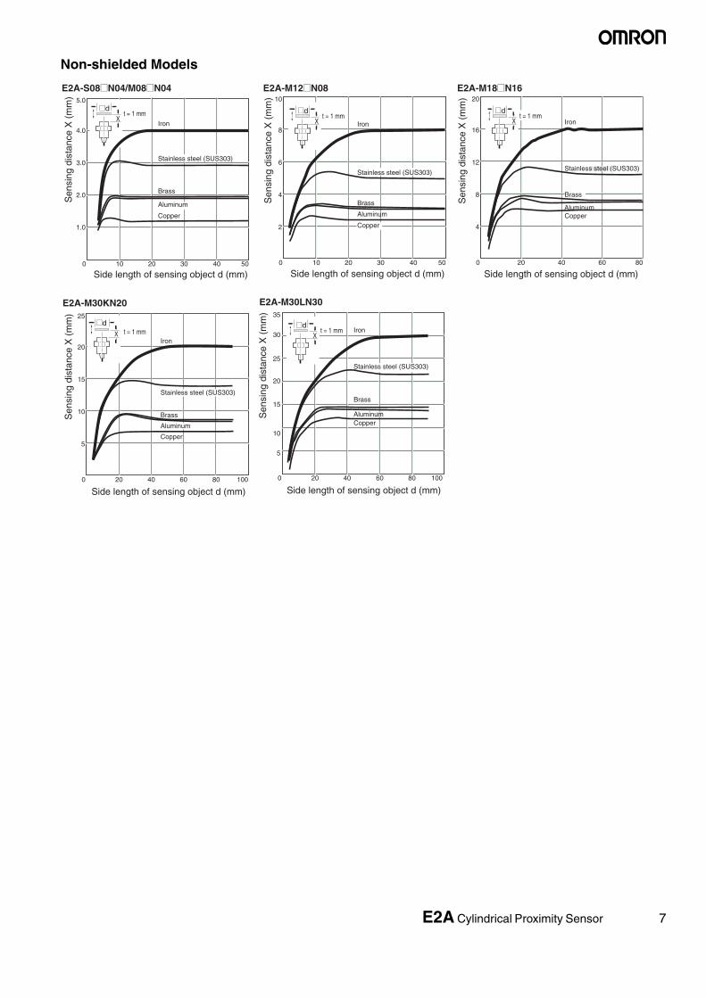
■ Model Number Legend
Example: E2A-M12LS04-M1-B1 Standard, M12, long barrel, shielded, Sn=4 mm, M12 connector, PNP-NOE2A-M08KN04-WP-B1 5M Standard, M8, short barrel, non-shielded, Sn=4 mm, pre-wired PVC cable, PNP-NO, cable length=5 m
1. Basic name
E2A
2. Sensing technology
Blank: Standard double distance
3. Housing shape and material
M: Cylindrical, metric threaded, brass
S: Cylindrical, metric threaded, stainless steel
4. Housing size
08: 8 mm
12: 12 mm
18: 18 mm
30: 30 mm
5. Barrel length
K: Standard length
L: Long body
6. Shield
S: Shielded
N: Non-shielded
7. Sensing distance
Numeral: Sensing distance: e.g. 02=2 mm, 16=16 mm
8. Kind of connection
WP: Pre-wired, PVC
M1: M12 connector (4-pole)
M3: M8 connector (4-pole)
M5: M8 connector (3-pole)
9. Power source and output
B: DC, 3-wire, PNP open collector
C: DC, 3-wire, NPN open collector
D: DC, 2-wire
E: DC, 3-wire, NPN voltage output
F: DC, 3-wire, PNP voltage output
10.Operation mode
1: Normally open (NO)
2: Normally closed (NC)
11.Specials (e.g., cable material, oscillating frequency)
12.Cable length
Blank: Connector type
Numeral: Cable type
2 3 4 5 6 7 8 9 10 111 12E2A@-@@@@@-@-@@-@@

4 E2A Cylindrical Proximity Sensor
Specifications
■ DC 3-wire Models
Note 1. The response frequency is an average value. Measurement conditions are as follows: standard target, a distance of twice the standard target distance between targets, and a setting distance of half the sensing distance.
2. When using any model at an ambient temperature between −40°C and −25°C and a power voltage between 30 and 32 VDC, use a load current of 100 mA max.,
3. For USA and CANADA : use class 2 circuit only.
Size M8 M12
Type Shielded Non-shielded Shielded Non-shielded
Item
E2A-M08@S02-M1-B1E2A-M08@S02-M1-B2E2A-M08@S02-M1-C1E2A-M08@S02-M1-C2E2A-S08@S02-@@-B1E2A-S08@S02-@@-B2E2A-S08@S02-@@-C1E2A-S08@S02-@@-C2
E2A-M08@N04-M1-B1E2A-M08@N04-M1-B2E2A-M08@N04-M1-C1E2A-M08@N04-M1-C2E2A-S08@N04-@@-B1E2A-S08@N04-@@-B2E2A-S08@N04-@@-C1E2A-S08@N04-@@-C2
E2A-M12@S04-@@-B1E2A-M12@S04-@@-B2E2A-M12@S04-@@-C1E2A-M12@S04-@@-C2
E2A-M12@N08-@@-B1E2A-M12@N08-@@-B2E2A-M12@N08-@@-C1E2A-M12@N08-@@-C2
Sensing distance 2 mm ± 10% 4 mm ± 10% 4 mm ± 10% 8 mm ± 10%
Setting distance 0 to 1.6 mm 0 to 3.2 mm 0 to 3.2 mm 0 to 6.4 mm
Differential travel 10% max. of sensing distance
Target Ferrous metal (The sensing distance decreases with non-ferrous metal.)
Standard target (mild steel ST37) 8×8×1 mm 12×12×1 mm 12×12×1 mm 24×24×1 mm
Response frequency (See note 1.) 1,500 Hz 1,000 Hz 1,000 Hz 800 Hz
Power supply voltage (operating voltage range)
12 to 24 VDC. Ripple (p-p): 10% max.(10 to 32 VDC)
Current consumption (DC 3-wire) 10 mA max.
Output type -B models: PNP open collector-C models: NPN open collector
Control output
Load current (See note 2.)
200 mA max. (32 VDC max.)
Residual voltage 2 V max. (under load current of 200 mA with cable length of 2 m)
Indicator Operation indicator (Yellow LED)
Operation mode (with sensing object approaching)
-B1/-C1 models: NO -B2/-C2 models: NCFor details, refer to the timing charts.
Protection circuit Power source circuit reverse polarity protection, Surge suppressor, Short-circuit protection
Output reverse polarity protection, Power source circuit reverse polarity protection, Surge suppres-sor, Short-circuit protection
Ambient air temperature Operating: −40°C to 70°C, Storage: −40°C to 85°C (with no icing or condensation)
Temperature influence (See note 2.) ±10% max. of sensing distance at 23°C within temperature range of −25°C to 70°C±15% max. of sensing distance at 23°C within temperature range of −40°C to 70°C
Ambient humidity Operating: 35% to 95%, Storage: 35% to 95%
Voltage influence ±1% max. of sensing distance in rated voltage range ±15%
Insulation resistance 50 MΩ min. (at 500 VDC) between current carry parts and case
Dielectric strength 1,000 VAC at 50/60 Hz for 1 min between current carry parts and case
Vibration resistance 10 to 55 Hz, 1.5-mm double amplitude for 2 hours each in X, Y and Z directions
Shock resistance 500 m/s2, 10 times each in X, Y and Z directions 1,000 m/s2, 10 times each in X, Y and Z directions
Standard and listings (See note 3.) IEC60529: IP67, Degree of protection EN60947-5-2: EMC
Connection method -WP models: Pre-wired models (Standard length: 2 m)-M1 models: M12 4-pin connector models-M5 models: M8 3-pin connector models
Weight (packaged)
Pre-wired model Approx. 65 g Approx. 85 g
M12 connector model M12 connector models: Approx. 20 gM8 connector models: Approx. 15 g
Approx. 35 g
Material Case Stainless steel or brass-nickel plated Brass-nickel plated
Sensing surface PBT
Cable PVC
Clamping nut Brass-nickel plated

E2A Cylindrical Proximity Sensor 5
■ DC 3-wire Models
Note 1. The response frequency is an average value. Measurement conditions are as follows: standard target, a distance of twice the standard target distance between targets, and a setting distance of half the sensing distance.
2. When using any model at an ambient temperature between -40°C and -25°C and a power voltage between 30 and 32 VDC, use a load current of 100 mA max.
3. For USA and CANADA : use class 2 circuit only.
Size M18 M30
Type Shielded Non-shielded Shielded Non-shielded Non-shielded
Item
E2A-M18@S08-@@-B1E2A-M18@S08-@@-B2E2A-M18@S08-@@-C1E2A-M18@S08-@@-C2
E2A-M18@N16-@@-B1E2A-M18@N16-@@-B2E2A-M18@N16-@@-C1E2A-M18@N16-@@-C2
E2A-M30@S15-@@-B1E2A-M30@S15-@@-B2E2A-M30@S15-@@-C1E2A-M30@S15-@@-C2
E2A-M30KN20-@@-B1E2A-M30KN20-@@-B2E2A-M30KN20-@@-C1E2A-M30KN20-@@-C2
E2A-M30LN30-@@-B1E2A-M30LN30-@@-B2E2A-M30LN30-@@-C1E2A-M30LN30-@@-C2
Sensing distance 8 mm±10% 16 mm±10% 15 mm±10% 20 mm±10% 30 mm±10%
Setting distance 0 to 6.4 mm 0 to 12.8 mm 0 to 12 mm 0 to 16 mm 0 to 24 mm
Differential travel 10% max. of sensing distance
Target Ferrous metal (The sensing distance decreases with non-ferrous metal.)
Standard target (mild steel ST37)
24×24×1 mm 48×48×1 mm 45×45×1 mm 60×60×1 mm 90×90×1 mm
Response frequency (See note 1.)
500 Hz 400 Hz 250 Hz 100 Hz 100 Hz
Power supply voltage (operating voltage range)
12 to 24 VDC. Ripple (p-p): 10% max.(10 to 32 VDC)
Current consumption (DC 3-wire)
10 mA max.
Output type -B models: PNP open collector-C models: NPN open collector
Control output
Load current (See note 2.)
200 mA max. (32 VDC max.)
Residual voltage 2 V max. (under load current of 200 mA with cable length of 2 m)
Indicator Operation indicator (Yellow LED)
Operation mode (with sensing object ap-proaching)
-B1/-C1 models: NO -B2/-C2 models: NCFor details, refer to the timing charts.
Protection circuit Output reverse polarity protection, Power source circuit reverse polarity protection, Surge suppressor, Short-circuit protection
Ambient air temperature Operating: −40°C to 70°C, Storage: −40°C to 85°C (with no icing or condensation)
Temperature influence (See note 2.)
±10% max. of sensing distance at 23°C within temperature range of −25°C to 70°C±15% max. of sensing distance at 23°C within temperature range of −40°C to 70°C
Ambient humidity Operating: 35% to 95%, Storage: 35% to 95%
Voltage influence ±1% max. of sensing distance in rated voltage range ±15%
Insulation resistance 50 MΩ min. (at 500 VDC) between current carry parts and case
Dielectric strength 1,000 VAC at 50/60 Hz for 1 min between current carry parts and case
Vibration resistance 10 to 55 Hz, 1.5-mm double amplitude for 2 hours each in X, Y and Z directions
Shock resistance 1,000 m/s2, 10 times each in X, Y and Z directions
Standard and listings (See note 3.)
IEC60529: IP67, Degree of protection EN60947-5-2: EMC
Connection method -WP models: Pre-wired models (Standard length: 2 m)-M1 models: M12 4-pin connector models-M5 models: M8 3-pin connector models
Weight (pack-aged)
Pre-wired model Approx. 160 g Approx. 280 g Approx. 280 g Approx. 370 g
M12 connector model
Approx. 70 g Approx. 200 g Approx. 200 g Approx. 260 g
Material Case Brass-nickel plated
Sensing surface PBT
Cable PVC
Clamping nut Brass-nickel plated

6 E2A Cylindrical Proximity Sensor
Engineering Data
Operating Range (Typical)
Influence of Sensing Object Size and Materials
Shielded Models
Distance Y (mm)
X
Y
18
16
14
12
10
8
6
4
2
0−30 −20 −10 0 10 20 30
E2A-M30@S15
Sen
sing
dis
tanc
e X
(m
m)
E2A-M18@S08
E2A-M12@S04E2A-S08@S02/ E2A-M08@S02
Shielded Models
X
Y
35
30
25
20
15
10
5
0−50 −40 −30 −20 −10 0 10 20 30 40 50
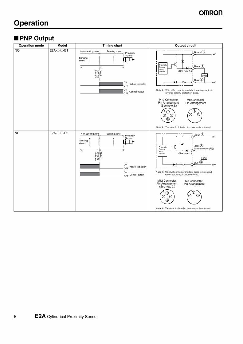
Non-shielded Models
Distance Y (mm)
Sen
sing
dis
tanc
e X
(m
m)
E2A-M30LN30
E2A-M18@N16
E2A-M12@N08
E2A-S08@N04/ E2A-M08@N04
E2A-M30KN20
0 5 10 15 20 25
Side length of sensing object d (mm)
Iron
@dt = 1 mm
X
0.5
1.0
1.5
2.0
2.5 5.0
4.0
3.0
2.0
1.0
0
@dt = 1 mm
X
5 10 15 20 25 30 35 0
1.0
2.0
3.0
4.0
5.0
7.0
8.0
6.0
10 20 30 40 50 60
@dt = 1 mm
X
0
4
8
12
16
20
10 20 30 40 50 60 70 80
@dt = 1 mm
X
Sen
sing
dis
tanc
e X
(m
m)
Stainless steel (SUS303)
Aluminum
Side length of sensing object d (mm)
Brass
Iron
Sen
sing
dis
tanc
e X
(m
m)
Stainless steel (SUS303)
Aluminum
Copper
Side length of sensing object d (mm)
Brass
Iron
Sen
sing
dis
tanc
e X
(m
m)
Copper
Stainless steel (SUS303)
Aluminum
E2A-S08@S02/M08@S02 E2A-M12@S04 E2A-M18@S08
E2A-M30@S15
Side length of sensing object d (mm)
Sen
sing
dis
tanc
e X
(m
m)
Iron
Stainless steel (SUS303)
Brass
Copper
Brass
Copper
Aluminum
E2A Cylindrical Proximity Sensor 7
Non-shielded Models
5.0
4.0
3.0
2.0
1.0
0 10 20 30 40 50
@dt = 1 mm
X
10
8
6
4
2
0
@dt = 1 mm
X
10 20 30 40 50
20
16
12
8
4
0
@dt = 1 mm
X
20 40 60 80
0
5
10
15
20
25
35
30
20 40 60 80 100
@dt = 1 mm
X
E2A-S08@N04/M08@N04
Side length of sensing object d (mm)
Sen
sing
dis
tanc
e X
(m
m)
Iron
Brass
Copper
Stainless steel (SUS303)
E2A-M12@N08
Side length of sensing object d (mm)S
ensi
ng d
ista
nce
X (
mm
)
Iron
Brass
Aluminum
Stainless steel (SUS303)
Copper
E2A-M18@N16
Side length of sensing object d (mm)
Sen
sing
dis
tanc
e X
(m
m)
Iron
Copper
Brass
Aluminum
E2A-M30LN30
Side length of sensing object d (mm)
Sen
sing
dis
tanc
e X
(m
m)
Iron
Copper
Brass
Aluminum
Stainless steel (SUS303)
Stainless steel (SUS303)
Aluminum
Side length of sensing object d (mm)
Sen
sing
dis
tanc
e X
(m
m) 25
20
15
10
5
0 20 40 60 80 100
t = 1 mm@d
X
Copper
Brass
Iron
Aluminum
Stainless steel (SUS303)
E2A-M30KN20
8 E2A Cylindrical Proximity Sensor
Operation
■ PNP OutputOperation mode Model Timing chart Output circuit
NO E2A-@-@-B1
NC E2A-@-@-B2
Sensingobject
(%) 100 0
Rated
sensingdistance
Sensing zoneNon-sensing zoneProximity Sensor
ON
OFF
ON
OFF
Yellow indicator
Control output
3
1
2 4 31
4
Load
Brown
Black
(See note 1.)
Blue
+V
0 V
Note 1: With M8 connector models, there is no output reverse polarity protection diode.
M12 Connector Pin Arrangement
(See note 2.)
M8 Connector Pin Arrangement
Note 2: Terminal 2 of the M12 connector is not used.
Proximity Sensor main circuits
(%) 100 0
Sensingobject
Rated
sensingdistance
Sensing zoneNon-sensing zoneProximity Sensor
ON
OFF
ON
OFF
Yellow indicator
Control output
3
1
2 4 31
4
Load
Brown
Black
(See note 1.)
Blue
+V
0 V
Note 1: With M8 connector models, there is no output reverse polarity protection diode.
M12 Connector Pin Arrangement
(See note 2.)
M8 Connector Pin Arrangement
Note 2: Terminal 4 of the M12 connector is not used.
Proximity Sensor main circuits
(M8 connector: )

E2A Cylindrical Proximity Sensor 9
■ NPN OutputOperation mode Model Timing chart Output circuit
NO E2A-@-@-C1
NC E2A-@-@-C2
Sensingobject
(%) 100 0
Rated
sensingdistance
Sensing zoneNon-sensing zoneProximity Sensor
ON
OFF
ON
OFF
Yellow indicator
Control output
Load
Brown
Black(See note 1.)
Blue
+V
0 V
Note 1: With M8 connector models, there is no output reverse polarity protection diode.
M12 Connector Pin Arrangement
(See note 2.)
3
1
2 4
M8 Connector Pin Arrangement
31
4
Note 2: Terminal 2 of the M12 connector is not used.
Proximity Sensor main circuits
(%) 100 0
Sensingobject
Rated
sensingdistance
Sensing zoneNon-sensing zoneProximity Sensor
ON
OFF
ON
OFF
Yellow indicator
Control output
3
1
2 4 31
4
Load
Brown
Black(See note 1.)
Blue
+V
0 V
Note 1: With M8 connector models, there is no output reverse polarity protection diode.
M12 Connector Pin Arrangement
(See note 2.)
M8 Connector Pin Arrangement
Note 2: Terminal 4 of the M12 connector is not used.
Proximity Sensor main circuits (M8 connector: )
10 E2A Cylindrical Proximity Sensor
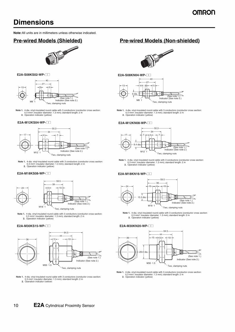
DimensionsNote:All units are in millimeters unless otherwise indicated.
Pre-wired Models (Shielded) Pre-wired Models (Non-shielded)
3 5
27
40
13
M8×1
(See note 1.)
E2A-S08KS02-WP-@@
3
40
5
27
13 6
M8×1
6 dia.
E2A-S08KN04-WP-@@
4
50.3
7
3417
M12×1Two, clamping nuts
E2A-M12KS04-WP-@@ E2A-M12KN08-WP-@@
4 7
34
50.3
17 7
9.4 dia.
M12×1
M18×1
4 10
39
59.5
24
E2A-M18KS08-WP-@@ E2A-M18KN16-WP-@@
1039
59.5
24 10 4
15.3 dia.
M18×1
E2A-M30KS15-WP-@@
5 10
64.5
44
36
M30×1.5
Note 1. 4-dia. vinyl-insulated round cable with 3 conductors (conductor cross section: 0.3 mm2; insulator diameter: 1.3 mm); standard length: 2 m
2. Operation indicator (yellow)
Indicator (See note 2.)(See note 1.)
(See note 1.)
(See note 1.)
(See note 1.)
(See note 1.)
(See note 1.)
Two, clamping nutsIndicator (See note 2.)
Note 1. 4-dia. vinyl-insulated round cable with 3 conductors (conductor cross section: 0.3 mm2; insulator diameter: 1.3 mm); standard length: 2 m
2. Operation indicator (yellow)
Two, clamping nuts
Indicator (See note 2.)
Note 1. 4-dia. vinyl-insulated round cable with 3 conductors (conductor cross section: 0.3 mm2; insulator diameter: 1.3 mm); standard length: 2 m
2. Operation indicator (yellow)
Two, clamping nuts
Indicator (See note 2.)
Note 1. 4-dia. vinyl-insulated round cable with 3 conductors (conductor cross section: 0.3 mm2; insulator diameter: 1.3 mm); standard length: 2 m
2. Operation indicator (yellow)
Two, clamping nuts
Indicator (See note 2.)
Note 1. 4-dia. vinyl-insulated round cable with 3 conductors (conductor cross section: 0.3 mm2; insulator diameter: 1.3 mm); standard length: 2 m
2. Operation indicator (yellow)
Two, clamping nuts
Note 1. 4-dia. vinyl-insulated round cable with 3 conductors (conductor cross section: 0.3 mm2; insulator diameter: 1.3 mm); standard length: 2 m
2. Operation indicator (yellow)
Indicator (See note 2.)
Two, clamping nuts
Note 1. 4-dia. vinyl-insulated round cable with 3 conductors (conductor cross section: 0.3 mm2; insulator diameter: 1.3 mm); standard length: 2 m
2. Operation indicator (yellow)
Indicator (See note 2.)M30×1.5
(See note 1.)
Two, clamping nuts
Note 1. 4-dia. vinyl-insulated round cable with 3 conductors (conductor cross section: 0.3 mm2; insulator diameter: 1.3 mm); standard length: 2 m
2. Operation indicator (yellow)
Indicator (See note 2.)
26.6 dia.
36 5
4415 10
64.5
E2A-M30KN20-WP-@@

E2A Cylindrical Proximity Sensor 11
M12×1
17
72.3
56
74
M12×1
17
72.3
56
747
9.4 dia.
M18×1
24
81.561
104
10
61 81.5
24 10 4
15.3 dia.
M18×1
5 10
86.566
36
M30×1.5
M30×1.5
26.6 dia.
105
6686.5
1536
(See note 1.) (See note 1.)
(See note 1.)
(See note 1.)
(See note 1.)
(See note 1.)
E2A-M12LS04-WP-@@
E2A-M18LS08-WP-@@
E2A-M12LN08-WP-@@
E2A-M18LN16-WP-@@
E2A-M30LN30-WP-@@E2A-M30LS15-WP-@@
Two, clamping nuts
Indicator (See note 2.)
Note 1. 4-dia. vinyl-insulated round cable with 3 conductors (conductor cross section: 0.3 mm2; insulator diameter: 1.3 mm); standard length: 2 m
2. Operation indicator (yellow)
Note 1. 4-dia. vinyl-insulated round cable with 3 conductors (conductor cross section: 0.3 mm2; insulator diameter: 1.3 mm); standard length: 2 m
2. Operation indicator (yellow)
Note 1. 4-dia. vinyl-insulated round cable with 3 conductors (conductor cross section: 0.3 mm2; insulator diameter: 1.3 mm); standard length: 2 m
2. Operation indicator (yellow)
Note 1. 4-dia. vinyl-insulated round cable with 3 conductors (conductor cross section: 0.3 mm2; insulator diameter: 1.3 mm); standard length: 2 m
2. Operation indicator (yellow) Note 1. 4-dia. vinyl-insulated round cable with 3 conductors (conductor cross section:
0.3 mm2; insulator diameter: 1.3 mm); standard length: 2 m2. Operation indicator (yellow)
Note 1. 4-dia. vinyl-insulated round cable with 3 conductors (conductor cross section: 0.3 mm2; insulator diameter: 1.3 mm); standard length: 2 m
2. Operation indicator (yellow)
Two, clamping nuts
Indicator (See note 2.)
Two, clamping nuts
Indicator (See note 2.)
Two, clamping nuts
Indicator (See note 2.)
Two, clamping nuts
Indicator (See note 2.)
Two, clamping nuts
Indicator (See note 2.)
Mounting Hole Cutout Dimensions
F
External diameter of Proximity Sensor Dimension F (mm)
M18
M30
M8
M12
8.5 dia.+0.50
12.5 dia.+0.50
18.5 dia.+0.50
30.5 dia.+0.50
3 549
62
13
M8×1
(See note 1.)
E2A-S08LS02-WP-@@
3
62
5
49
13 6
M8×1
6 dia.
E2A-S08LN04-WP-@@
(See note 1.)
Two, clamping nutsIndicator (See note 2.)
Note 1. 4-dia. vinyl-insulated round cable with 3 conductors (conductor cross section: 0.3 mm2; insulator diameter: 1.3 mm); standard length: 2 m
2. Operation indicator (yellow)
Two, clamping nuts
Indicator (See note 2.)
Note 1. 4-dia. vinyl-insulated round cable with 3 conductors (conductor cross section: 0.3 mm2; insulator diameter: 1.3 mm); standard length: 2 m
2. Operation indicator (yellow)

12 E2A Cylindrical Proximity Sensor
M12 Connector Models (Shielded) M12 Connector Models (Non-shielded)
E2A-S08KS02-M1-@@E2A-M08KS02-M1-@@
E2A-M12KS04-M1-@@ E2A-M12KN08-M1-@@
27
43
3 513
M8×1
M12×1
Note: Operation indicator (yellow LED, 4×90°)
E2A-S08KN04-M1-@@E2A-M08KN04-M1-@@
6 dia.
3 527
43
613
M8×1
M12×1
E2A-M18KS08-M1-@@ E2A-M18KN16-M1-@@
74
34
48
17
M12×1
M12×1
9.4 dia.
4
34
48
7 7
17
M12×1
M12×1
1024 4
39
53
M18×1
M12×124 104
39
53
10
15.3 dia.
M18×1
M12×1
E2A-M30KS15-M1-@@
44
5
58
36 10
M30×1.5
M12×1
Note: Operation indicator (yellow LED, 4×90°)
Note: Operation indicator (yellow LED, 4×90°)
Note: Operation indicator (yellow LED, 4×90°)
Note: Operation indicator (yellow LED, 4×90°)
Note: Operation indicator (yellow LED, 4×90°)
Note: Operation indicator (yellow LED, 4×90°)
Two, clamping nutsIndicator (See note.)
Two, clamping nuts
Indicator (See note.)
Two, clamping nuts
Indicator (See note.)
Two, clamping nuts
Indicator (See note.)
Two, clamping nuts
Indicator (See note.)
Two, clamping nuts
Indicator (See note.)
Two, clamping nuts
Indicator (See note.)
26.6 dia.
M12×1
Note: Operation indicator (yellow LED, 4×90°)
51536
44
10
58
M30×1.5
Indicator (See note.)
Two, clamping nuts
E2A-M30KN20-M1-@@

E2A Cylindrical Proximity Sensor 13
M8 Connector Models (Shielded) M8 Connector Models (Non-shielded)
74
56
70
17
M12×1
M12×1
9.4 dia.
4
56
70
7717
M12×1
M12×1
1024 4
61
75
M18×1
M12×1
24 104
6175
10
15.3 dia.
M18×1
M12×1
665
80
36 10
M30×1.5
M12×1
1051566
80
36
26.6 dia.
M30×1.5
Note: Operation indicator (yellow LED, 4×90°)
Note: Operation indicator (yellow LED, 4×90°)
Note: Operation indicator (yellow LED, 4×90°)
Note: Operation indicator (yellow LED, 4×90°)
Note: Operation indicator (yellow LED, 4×90°)
Note: Operation indicator (yellow LED, 4×90°)
E2A-M12LS04-M1-@@
E2A-M18LS08-M1-@@
E2A-M30LS15-M1-@@
E2A-M12LN08-M1-@@
E2A-M18LN16-M1-@@
E2A-M30LN30-M1-@@
Two, clamping nutsIndicator (See note.)
Two, clamping nuts
Indicator (See note.)
Two, clamping nuts
Indicator (See note.)
Two, clamping nuts
Indicator (See note.)
Two, clamping nuts
Indicator (See note.)
Two, clamping nutsIndicator (See note.)
E2A-S08LS02-M1-@@E2A-M08LS02-M1-@@
49
65
3 513
M8×1
M12×1
Note: Operation indicator (yellow LED, 4×90°)
E2A-S08LN04-M1-@@E2A-M08LN04-M1-@@
6 dia.
3 549
65
613
M8×1
M12×1
Note: Operation indicator (yellow LED, 4×90°)
Two, clamping nutsIndicator (See note.) Indicator (See note.)
M8×1
M8×1
E2A-S08KS02-M5-@@ E2A-S08KN04-M5-@@
6 dia.
3613 5
27
39
M8×1
M8×1
Note: Operation indicator (yellow LED, 4×90°) Note: Operation indicator (yellow LED, 4×90°)
313
27
5
39
Two, clamping nuts Two, clamping nuts
M8×1
M8×1
E2A-S08LS02-M5-@@ E2A-S08LN04-M5-@@
6 dia.
3613 5
49
61
M8×1
M8×1
Note: Operation indicator (yellow LED, 4×90°) Note: Operation indicator (yellow LED, 4×90°)
313
49
5
61

14 E2A Cylindrical Proximity Sensor
Precautions
■ Safety Precautions
Power SupplyDo not impose an excessive voltage on the E2A, otherwise it may bedamaged. Do not impose AC current (100 to 240 VAC) on any DCmodel, otherwise it may be damaged.
Load Short-circuitDo not short-circuit the load, or the E2A may be damaged.
The E2A’s short-circuit protection function will be valid if the polarityof the supply voltage imposed is correct and within the rated voltagerange.
WiringBe sure to wire the E2A and load correctly, otherwise it may be dam-aged.
Connection with No LoadBe sure to insert loads when wiring. Make sure to connect a properload to the E2A in operation, otherwise it may damage internal ele-ments.
Do not expose the product to flammable or explo-sive gases.
Do not disassemble, repair, or modify the product.
■ Correct Use
Designing
Power Reset TimeThe Proximity Sensor is ready to operate within 100 ms after poweris supplied. If power supplies are connected to the Proximity Sensorand load respectively, be sure to supply power to the Proximity Sen-sor before supplying power to the load.
Effects of Surrounding MetalWhen mounting the E2A within a metal panel, ensure that the clear-ances given in the following table are maintained.
(Unit: mm)
Note 1. In the case of using the supplied nuts. If true flash mounting is necessary, apply a free zone of 1.5 mm.
2. In the case of using the supplied nuts. If true flush mounting is necessary, apply a free zone of 4 mm.
Power OFFThe Proximity Sensor may output a pulse signal when it is turnedOFF. Therefore, it is recommended that the load be turned OFFbefore turning OFF the Proximity Sensor.
Power Supply TransformerWhen using a DC power supply, make sure that the DC power sup-ply has an insulated transformer. Do not use a DC power supply withan auto-transformer.
Mutual InterferenceWhen installing two or more Sensors face-to-face or side-by-side,ensure that the minimum distances given in the following table aremaintained.
(Unit: mm)Type Dimension M8 M12 M18 M30
Short barrel
Long barrel
Shielded l 0 0 0 (See note 1.)
0 (See note 2.)
m 4.5 12 24 45
d --- --- 27 45
D 0 0 1.5 4
n 12 18 27 45
Non-shielded
l 12 15 22 30 40
m 8 20 48 70 90
d 24 40 70 90 120
D 12 15 22 30 40
n 24 40 70 90 120
l
mn
mD
d dia.
l
Type Dimension M8 M12 M18 M30
Short barrel
Long barrel
Shielded A 20 30 60 110
B 15 20 35 70
Non-shielded
A 80 120 200 300 300
B 60 100 120 200 300

E2A Cylindrical Proximity Sensor 15
Wiring
High-tension LinesWiring through Metal Conduit:If there is a power or high-tension line near the cable of the ProximitySensor, wire the cable through an independent metal conduit to pre-vent against Proximity Sensor damage or malfunctioning.
Cable ExtensionStandard cable length is less than 200 m.
The tractive force is 50 N.
MountingThe Proximity Sensor must not be subjected to excessive shock witha hammer when it is installed, otherwise the Proximity Sensor maybe damaged or lose its water-resistivity.
Do not tighten the nut with excessive force. A washer must be usedwith the nut.
Maintenance and InspectionPeriodically perform the following checks to ensure stable operationof the Proximity Sensor over a long period of time.
1. Check for mounting position, dislocation, looseness, or distortionof the Proximity Sensor and sensing objects.
2. Check for loose wiring and connections, improper contacts, andline breakage.
3. Check for attachment or accumulation of metal powder or dust.4. Check for abnormal temperature conditions and other environ-
mental conditions.5. Check for proper lighting of indicators (for models with a set indi-
cator.)
Never disassemble or repair the Sensor.
Environment
Water ResistivityDo not use the Proximity Sensor underwater, outdoors, or in the rain.
Operating EnvironmentBe sure to use the Proximity Sensor within its operating ambienttemperature range and do not use the Proximity Sensor outdoors sothat its reliability and life expectancy can be maintained. Althoughthe Proximity Sensor is water resistive, a cover to protect the Prox-imity Sensor from water or water-soluble machining oil is recom-mended so that its reliability and life expectancy can be maintained.
Do not use the Proximity Sensor in an environment with chemicalgas (e.g., strong alkaline or acid gasses including nitric, chromic,and concentrated sulfuric acid gases).
Inrush CurrentA load that has a large inrush current (e.g., a lamp or motor) willdamage the Proximity Sensor, in which case connect the load to theProximity Sensor through a relay.
Type Torque
M8 Stainless steel type 9 Nm
Brass type 4 Nm
M12 30 Nm
M18 70 Nm
M30 180 Nm

16
<SUITABILITY FOR USE>OMRON shall not be responsible for conformity with any standards, codes, or regulations that apply to the combination of the products in the customer’s application or use of the products.
Take all necessary steps to determine the suitability of the product for the systems, machines, and equipment with which it will be used.
<CHANGE IN SPECIFICATIONS>Product specifications and accessories may be changed at any time based on improvements and other reasons. Consult with your OMRON representative at any time to confirm actual specifications of purchased product.
In the interest of product improvement, specifications are subject to change without notice.
ALL DIMENSIONS SHOWN ARE IN MILLIMETERS.To convert millimeters into inches, multiply by 0.03937. To convert grams into ounces, multiply by 0.03527.

Terms and Conditions of Sale1. Offer; Acceptance. These terms and conditions (these "Terms") are deemed
part of all quotes, agreements, purchase orders, acknowledgments, price lists,catalogs, manuals, brochures and other documents, whether electronic or inwriting, relating to the sale of products or services (collectively, the "Products")by Omron Electronics LLC and its subsidiary companies (“Omron”). Omronobjects to any terms or conditions proposed in Buyer’s purchase order or otherdocuments which are inconsistent with, or in addition to, these Terms.
2. Prices; Payment Terms. All prices stated are current, subject to change with-out notice by Omron. Omron reserves the right to increase or decrease priceson any unshipped portions of outstanding orders. Payments for Products aredue net 30 days unless otherwise stated in the invoice.
3. Discounts. Cash discounts, if any, will apply only on the net amount of invoicessent to Buyer after deducting transportation charges, taxes and duties, and willbe allowed only if (i) the invoice is paid according to Omron’s payment termsand (ii) Buyer has no past due amounts.
4. Interest. Omron, at its option, may charge Buyer 1-1/2% interest per month orthe maximum legal rate, whichever is less, on any balance not paid within thestated terms.
5. Orders. Omron will accept no order less than $200 net billing. 6. Governmental Approvals. Buyer shall be responsible for, and shall bear all
costs involved in, obtaining any government approvals required for the impor-tation or sale of the Products.
7. Taxes. All taxes, duties and other governmental charges (other than generalreal property and income taxes), including any interest or penalties thereon,imposed directly or indirectly on Omron or required to be collected directly orindirectly by Omron for the manufacture, production, sale, delivery, importa-tion, consumption or use of the Products sold hereunder (including customsduties and sales, excise, use, turnover and license taxes) shall be charged toand remitted by Buyer to Omron.
8. Financial. If the financial position of Buyer at any time becomes unsatisfactoryto Omron, Omron reserves the right to stop shipments or require satisfactorysecurity or payment in advance. If Buyer fails to make payment or otherwisecomply with these Terms or any related agreement, Omron may (without liabil-ity and in addition to other remedies) cancel any unshipped portion of Prod-ucts sold hereunder and stop any Products in transit until Buyer pays allamounts, including amounts payable hereunder, whether or not then due,which are owing to it by Buyer. Buyer shall in any event remain liable for allunpaid accounts.
9. Cancellation; Etc. Orders are not subject to rescheduling or cancellationunless Buyer indemnifies Omron against all related costs or expenses.
10. Force Majeure. Omron shall not be liable for any delay or failure in deliveryresulting from causes beyond its control, including earthquakes, fires, floods,strikes or other labor disputes, shortage of labor or materials, accidents tomachinery, acts of sabotage, riots, delay in or lack of transportation or therequirements of any government authority.
11. Shipping; Delivery. Unless otherwise expressly agreed in writing by Omron:a. Shipments shall be by a carrier selected by Omron; Omron will not drop ship
except in “break down” situations.b. Such carrier shall act as the agent of Buyer and delivery to such carrier shall
constitute delivery to Buyer;c. All sales and shipments of Products shall be FOB shipping point (unless oth-
erwise stated in writing by Omron), at which point title and risk of loss shallpass from Omron to Buyer; provided that Omron shall retain a security inter-est in the Products until the full purchase price is paid;
d. Delivery and shipping dates are estimates only; ande. Omron will package Products as it deems proper for protection against nor-
mal handling and extra charges apply to special conditions.12. Claims. Any claim by Buyer against Omron for shortage or damage to the
Products occurring before delivery to the carrier must be presented in writingto Omron within 30 days of receipt of shipment and include the original trans-portation bill signed by the carrier noting that the carrier received the Productsfrom Omron in the condition claimed.
13. Warranties. (a) Exclusive Warranty. Omron’s exclusive warranty is that theProducts will be free from defects in materials and workmanship for a period oftwelve months from the date of sale by Omron (or such other period expressedin writing by Omron). Omron disclaims all other warranties, express or implied.(b) Limitations. OMRON MAKES NO WARRANTY OR REPRESENTATION,EXPRESS OR IMPLIED, ABOUT NON-INFRINGEMENT, MERCHANTABIL-
ITY OR FITNESS FOR A PARTICULAR PURPOSE OF THE PRODUCTS.BUYER ACKNOWLEDGES THAT IT ALONE HAS DETERMINED THAT THEPRODUCTS WILL SUITABLY MEET THE REQUIREMENTS OF THEIRINTENDED USE. Omron further disclaims all warranties and responsibility ofany type for claims or expenses based on infringement by the Products or oth-erwise of any intellectual property right. (c) Buyer Remedy. Omron’s sole obli-gation hereunder shall be, at Omron’s election, to (i) replace (in the formoriginally shipped with Buyer responsible for labor charges for removal orreplacement thereof) the non-complying Product, (ii) repair the non-complyingProduct, or (iii) repay or credit Buyer an amount equal to the purchase price ofthe non-complying Product; provided that in no event shall Omron be responsi-ble for warranty, repair, indemnity or any other claims or expenses regardingthe Products unless Omron’s analysis confirms that the Products were prop-erly handled, stored, installed and maintained and not subject to contamina-tion, abuse, misuse or inappropriate modification. Return of any Products byBuyer must be approved in writing by Omron before shipment. Omron Compa-nies shall not be liable for the suitability or unsuitability or the results from theuse of Products in combination with any electrical or electronic components,circuits, system assemblies or any other materials or substances or environ-ments. Any advice, recommendations or information given orally or in writing,are not to be construed as an amendment or addition to the above warranty.See http://www.omron247.com or contact your Omron representative for pub-lished information.
14. Limitation on Liability; Etc. OMRON COMPANIES SHALL NOT BE LIABLEFOR SPECIAL, INDIRECT, INCIDENTAL, OR CONSEQUENTIAL DAMAGES,LOSS OF PROFITS OR PRODUCTION OR COMMERCIAL LOSS IN ANYWAY CONNECTED WITH THE PRODUCTS, WHETHER SUCH CLAIM ISBASED IN CONTRACT, WARRANTY, NEGLIGENCE OR STRICT LIABILITY.Further, in no event shall liability of Omron Companies exceed the individualprice of the Product on which liability is asserted.
15. Indemnities. Buyer shall indemnify and hold harmless Omron Companies andtheir employees from and against all liabilities, losses, claims, costs andexpenses (including attorney's fees and expenses) related to any claim, inves-tigation, litigation or proceeding (whether or not Omron is a party) which arisesor is alleged to arise from Buyer's acts or omissions under these Terms or inany way with respect to the Products. Without limiting the foregoing, Buyer (atits own expense) shall indemnify and hold harmless Omron and defend or set-tle any action brought against such Companies to the extent based on a claimthat any Product made to Buyer specifications infringed intellectual propertyrights of another party.
16. Property; Confidentiality. Any intellectual property in the Products is the exclu-sive property of Omron Companies and Buyer shall not attempt to duplicate itin any way without the written permission of Omron. Notwithstanding anycharges to Buyer for engineering or tooling, all engineering and tooling shallremain the exclusive property of Omron. All information and materials suppliedby Omron to Buyer relating to the Products are confidential and proprietary,and Buyer shall limit distribution thereof to its trusted employees and strictlyprevent disclosure to any third party.
17. Export Controls. Buyer shall comply with all applicable laws, regulations andlicenses regarding (i) export of products or information; (iii) sale of products to“forbidden” or other proscribed persons; and (ii) disclosure to non-citizens ofregulated technology or information.
18. Miscellaneous. (a) Waiver. No failure or delay by Omron in exercising any rightand no course of dealing between Buyer and Omron shall operate as a waiverof rights by Omron. (b) Assignment. Buyer may not assign its rights hereunderwithout Omron's written consent. (c) Law. These Terms are governed by thelaw of the jurisdiction of the home office of the Omron company from whichBuyer is purchasing the Products (without regard to conflict of law princi-ples). (d) Amendment. These Terms constitute the entire agreement betweenBuyer and Omron relating to the Products, and no provision may be changedor waived unless in writing signed by the parties. (e) Severability. If any provi-sion hereof is rendered ineffective or invalid, such provision shall not invalidateany other provision. (f) Setoff. Buyer shall have no right to set off any amountsagainst the amount owing in respect of this invoice. (g) Definitions. As usedherein, “including” means “including without limitation”; and “Omron Compa-nies” (or similar words) mean Omron Corporation and any direct or indirectsubsidiary or affiliate thereof.
Certain Precautions on Specifications and Use1. Suitability of Use. Omron Companies shall not be responsible for conformity
with any standards, codes or regulations which apply to the combination of theProduct in the Buyer’s application or use of the Product. At Buyer’s request,Omron will provide applicable third party certification documents identifyingratings and limitations of use which apply to the Product. This information byitself is not sufficient for a complete determination of the suitability of the Prod-uct in combination with the end product, machine, system, or other applicationor use. Buyer shall be solely responsible for determining appropriateness ofthe particular Product with respect to Buyer’s application, product or system.Buyer shall take application responsibility in all cases but the following is anon-exhaustive list of applications for which particular attention must be given:(i) Outdoor use, uses involving potential chemical contamination or electricalinterference, or conditions or uses not described in this document.(ii) Use in consumer products or any use in significant quantities. (iii) Energy control systems, combustion systems, railroad systems, aviationsystems, medical equipment, amusement machines, vehicles, safety equip-ment, and installations subject to separate industry or government regulations. (iv) Systems, machines and equipment that could present a risk to life or prop-erty. Please know and observe all prohibitions of use applicable to this Prod-uct. NEVER USE THE PRODUCT FOR AN APPLICATION INVOLVING SERIOUSRISK TO LIFE OR PROPERTY OR IN LARGE QUANTITIES WITHOUTENSURING THAT THE SYSTEM AS A WHOLE HAS BEEN DESIGNED TO
ADDRESS THE RISKS, AND THAT THE OMRON’S PRODUCT IS PROP-ERLY RATED AND INSTALLED FOR THE INTENDED USE WITHIN THEOVERALL EQUIPMENT OR SYSTEM.
2. Programmable Products. Omron Companies shall not be responsible for theuser’s programming of a programmable Product, or any consequence thereof.
3. Performance Data. Data presented in Omron Company websites, catalogsand other materials is provided as a guide for the user in determining suitabil-ity and does not constitute a warranty. It may represent the result of Omron’stest conditions, and the user must correlate it to actual application require-ments. Actual performance is subject to the Omron’s Warranty and Limitationsof Liability.
4. Change in Specifications. Product specifications and accessories may bechanged at any time based on improvements and other reasons. It is our prac-tice to change part numbers when published ratings or features are changed,or when significant construction changes are made. However, some specifica-tions of the Product may be changed without any notice. When in doubt, spe-cial part numbers may be assigned to fix or establish key specifications foryour application. Please consult with your Omron’s representative at any timeto confirm actual specifications of purchased Product.
5. Errors and Omissions. Information presented by Omron Companies has beenchecked and is believed to be accurate; however, no responsibility is assumedfor clerical, typographical or proofreading errors or omissions.

OMRON CANADA, INC. • HEAD OFFICEToronto, ON, Canada • 416.286.6465 • 866.986.6766 • www.omron247.com
OMRON ELECTRONICS DE MEXICO • HEAD OFFICEMéxico DF • 52.55.59.01.43.00 • 001.800.556.6766 • [email protected]
OMRON ELECTRONICS DE MEXICO • SALES OFFICEApodaca, N.L. • 52.81.11.56.99.20 • 001.800.556.6766 • [email protected]
OMRON ELETRÔNICA DO BRASIL LTDA • HEAD OFFICESão Paulo, SP, Brasil • 55.11.2101.6300 • www.omron.com.br
OMRON ARGENTINA • SALES OFFICECono Sur • 54.11.4783.5300
OMRON CHILE • SALES OFFICESantiago • 56.9.9917.3920
OTHER OMRON LATIN AMERICA SALES54.11.4783.5300
OMRON INDUSTRIAL AUTOMATION • THE AMERICAS HEADQUARTERSSchaumburg, IL USA • 847.843.7900 • 800.556.6766 • www.omron247.com
OMRON EUROpE B.V. • Wegalaan 67-69, NL-2132 JD, Hoofddorp, The Netherlands. • Tel: +31 (0) 23 568 13 00Fax: +31 (0) 23 568 13 88 • www.industrial.omron.eu
Cat. No. D096-D1-01B 12/13 Note: Specifications are subject to change. © 2013 Omron Electronics LLC Printed in U.S.A.


![Cylindrical Compact Inductive Proximity Sensor [Amplifier Built-in] … · 2017-05-02 · INDUCTIVE PROXIMITY SENSORS PARTICULAR SENSOR OPTIONS SIMPLE WIRE-SAVING UNITS SYSTEMS MEASUREMENT](https://img.dokumen.tips/doc/110x75/5f3c7ecb6f22dd6ba91fdd02/cylindrical-compact-inductive-proximity-sensor-amplifier-built-in-2017-05-02.jpg)