Embed Size (px)
Citation preview

EVERY LIFE HAS A PURPOSE…
FlameGard 5 UV/IR Flame Detector
The Benefits of HART on Installation and
Maintenance of Flame Detectors
FlameGard 5 UV/IR Flame Detector
The Benefits of HART on Installation and
Maintenance of Flame Detectors
Contents
1. Product Overview2. Principle of Operation3. Spectral Range for Flame Detection4. Field of View5. Detector Placement6. Wiring7. Test Lamp Check8. Fault Conditions9. HART10. Applications11. Conclusion

FlameGard 5 UV/IR Flame Detector
Description HART enabled flame detector with ultraviolet
and infrared sensors
Customer Benefits Features wide field of view, enhanced false
alarm response, COPM, and broad temperature range
Stores time-stamped records of warnings, alarms, and maintenance events
Supports HART communication Compatible with Emerson Process
Management’s AMS Intelligent Device Manager Better protection against electromagnetic
emissions

Principle of Operation
Measures the radiant intensity of light and fluctuations of radiant intensity to detect a flame Monitors spectral range in
ultraviolet (185 – 260 nm) and infrared (4.35 m)
Provides warning when both UV and IR sensors respond to a flame
0
5
10
15
20
25
30
Analog Output (mA)
UV IR UV and IR

Spectral Range

Field of View
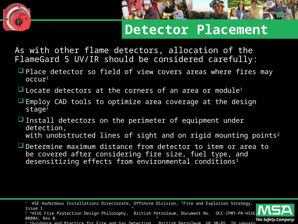
Detector Placement
As with other flame detectors, allocation of the FlameGard 5 UV/IR should be considered carefully: Place detector so field of view covers areas where fires may occur1
Locate detectors at the corners of an area or module1
Employ CAD tools to optimize area coverage at the design stage1
Install detectors on the perimeter of equipment under detection, with unobstructed lines of sight and on rigid mounting points2
Determine maximum distance from detector to item or area to be covered after considering fire size, fuel type, and desensitizing effects from environmental conditions3
1 HSE Hazardous Installations Directorate, Offshore Division, “Fire and Explosion Strategy, Issue 1.”2 “HSSE Fire Protection Design Philosophy,” British Petroleum, Document No. OCC-IPMT-PR-HSSE-00004, Rev 0.3 “Guidance and Practice for Fire and Gas Detection,” British Petroleum, GP 30-85, 29 January 2003.

Wiring
No TB1 Function TB2 Function
1 DATA+ CHAS GND
2 DATA- ALM C
3 RESET ALM 1
4 ALMTEST ALM 2
50-20mA DATA2+
WARN C
6 DATA2- WARN 1
7 +24VDC WARN 2
8 +24VDC FLT C
9 COM FLT 1
10 COM FLT 2
Terminal Block 2 Terminal Block 1
10987654321
Term #
123456789
10
Term #

Test Lamp Check
ModelMaximum Distance to
Detector (ft)
FlameGard 5 UV/IR 20
FlameGard 5 UV/IR-H2 40
Test lamp check allows independent verification of detector’s operation
Regardless of approach used to activate test mode, each time a FlameGard 5 UV/IR
successfully detects the test lamp, it records a time stamp of the event

Fault Conditions
Self-diagnostics show specific device failures
Bit Position Description
High 8 Reset Line Shorted
High 7 UV 10 Minute
High 4 Output Current Fault
Low 8 Flash Checksum
Low 7 EEPROM Checksum
Low 6 RAM Test
Low 5 Low Line Voltage Check
Low 4 UV COPM
Low 3 IR COPM
Low 1 Internal Voltage

HART
Configuration available with HART protocol Provides uniform and consistent communication for all field devices Continuous, real time diagnostic, process, and maintenance data
Function
Analog Current (mA)
Analog Output (Standard)
ModbusHART
(Default)HART-modified Analog Output
Startup 0 to 0.2 0 to 0.2 3.5 ± 0.1 1.25 ± 0.1
Fault 0 to 0.2 0 to 0.2 3.5 ± 0.1 1.25 ± 0.1
COPM Fault 2.0 ± 0.1 2.0 ± 0.1 3.5 ± 0.1 2.0 ± 0.1
Ready Signal 4.05 ± 0.05 4.05 ± 0.05 4.05 ± 0.05 4.05 ± 0.05
IR 8.0 ± 0.1 8.0 ± 0.1 8.0 ± 0.1 8.0 ± 0.1
UV 12.0 ± 0.1 12.0 ± 0.1 12.0 ± 0.1 12.0 ± 0.1
Warn 16.0 ± 0.1 16.0 ± 0.1 16.0 ± 0.1 16.0 ± 0.1
Alarm 20.0 ± 0.1 20.0 ± 0.1 20.0 ± 0.1 20.0 ± 0.1
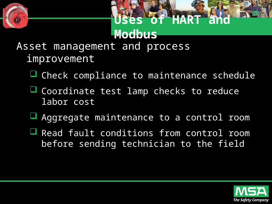
Uses of HART and Modbus
Asset management and process improvement
Check compliance to maintenance schedule
Coordinate test lamp checks to reduce labor cost
Aggregate maintenance to a control room
Read fault conditions from control room before sending technician to the field

Applications
The FlameGard 5 UV/IR is suited for a wide range of applications: Gas Compressor Stations Pipelines Gas Turbine Power Plants Oil and Gas Terminals Refineries Oil and Gas Storage Tanks Oil and Gas Platforms
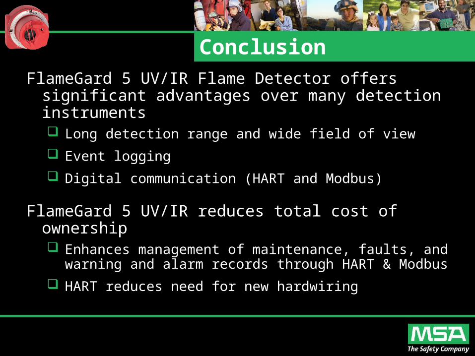
Conclusion
FlameGard 5 UV/IR Flame Detector offers significant advantages over many detection instruments Long detection range and wide field of view
Event logging
Digital communication (HART and Modbus)
FlameGard 5 UV/IR reduces total cost of ownership Enhances management of maintenance, faults, and
warning and alarm records through HART & Modbus
HART reduces need for new hardwiring

Conclusion
HART and Modbus communication allow users to get the full benefit from the FlameGard 5 UV/IR Flame Detector Real time device diagnostics enable proactive action
to avoid process disruptions and unplanned shutdowns
Digital communication ensures that device information can be linked remotely to other digital networks
Advanced diagnostics help increase safety integrity levels
When connected to plant asset management software, digital communication protocols enable greater operations efficiencies