Embed Size (px)
Citation preview


Contents
Deciding whether to use this guide ............................................................. 6Cabling concepts and best practices ........................................................... 7
Cabling concepts ......................................................................................................... 7
Fabric (switched) topologies compared to direct-attach topologies ................ 7
Trays and shelves ............................................................................................ 7
Host channels and drive channels ................................................................... 8
Host ports and drive ports ............................................................................... 9
Dual-ported drives ........................................................................................... 9
Preferred controllers and alternate controllers ................................................ 9
Alternate path software ................................................................................... 9
Failover ............................................................................................................ 9
Redundant and non-redundant components .................................................. 10
Single point of failure .................................................................................... 10
SFP transceivers, fiber-optic cables, and copper cables ................................ 10
Host adapters ................................................................................................. 11
Host interface cards ....................................................................................... 11
Network interface cards ................................................................................. 12
Switches and zoning ...................................................................................... 12
In-band management and out-of-band management ..................................... 12
Best practices ............................................................................................................. 12
Drive shelf cabling for redundancy ............................................................... 12
Host cabling for redundancy ......................................................................... 13
Cabling for performance ............................................................................... 13
How best to approach zone configuration ..................................................... 13
Host and storage array cabling for mirroring ................................................ 13
Single-controller topologies and dual-controller topologies ......................... 14
Adding new drive shelves to an existing storage array ................................. 14
Cabling for different management methods .................................................. 14
Labeling cables .............................................................................................. 16
Cabling information provided by storage management software ................. 16
Common procedures ................................................................................................. 16
Handling static-sensitive components ........................................................... 16
Installing an SFP transceiver and a fiber-optic cable .................................... 17
Installing a copper cable with a integrated SFP transceiver .......................... 18
Installing an RJ-45 cable for iSCSI connections ........................................... 19
Installing a SAS cable ................................................................................... 20
Component locations .................................................................................. 22Component locations on the E5700 controller shelves ............................................. 22
Component locations on the E5600 controller-drive trays and the EF560 flash
arrays ................................................................................................................... 26
Table of Contents | 3

Component locations on the E2800 controller shelves and the EF280 flash
arrays ................................................................................................................... 32
Component locations on the E2700 controller-drive trays ........................................ 37
Component locations on the DE460C drive shelf ..................................................... 45
Component locations on the DE6600 drive shelf (drive tray) ................................... 46
Component locations on the DE212C drive shelf and the DE224C drive shelf ........ 47
Component locations on the DE1600 drive shelf (drive tray) and the DE5600
drive shelf (drive tray) ......................................................................................... 48
Host cabling ................................................................................................. 51Host interface connections ........................................................................................ 51
Maximum number of host connections ..................................................................... 57
Direct-attach topologies ............................................................................................ 57
Direct host connections to one controller shelf or controller-drive tray ....... 57
One host with direct SAS connections to four controller shelves or
controller-drive trays ............................................................................... 59
Switch topologies ...................................................................................................... 60
Mixed topologies ....................................................................................................... 63
Drive shelf or drive tray cabling ............................................................... 65Drive shelf (drive tray) information by model .......................................................... 65
ESM module and IOM module arrangements ........................................................... 66
Drive cabling topologies for the E5700 controller shelves and the EF570 flash
arrays ................................................................................................................... 68
Drive channel redundancy for the E5700 controller shelves ......................... 69
Drive cabling topologies for the E5724 controller shelf and EF570 flash
array ......................................................................................................... 71
Drive cabling topologies for the E5760 controller shelf ............................... 73
Drive tray cabling topologies for the E5600 controller-drive trays and EF560
flash arrays ........................................................................................................... 75
Drive channel redundancy for the E5600 controller drive trays and
EF560 flash arrays ................................................................................... 76
Drive tray cabling topologies for the E5612 and E5624 controller-drive
trays and EF560 flash arrays ................................................................... 78
Drive tray cabling topologies for the E5660 controller-drive tray ................ 81
Drive cabling topologies for the E2800 controller shelves and the EF280 flash
array ..................................................................................................................... 84
Drive channel redundancy for the E2800 controller shelves ......................... 84
Drive cabling topologies for the E2824 and E2812 controller shelves
and the EF280 flash array ........................................................................ 87
Drive cabling topologies for the E2860 controller shelf ............................... 89
Drive tray cabling topologies for the E2700 controller-drive trays ........................... 91
Drive channel redundancy for the E2700 controller-drive trays ................... 91
Drive tray cabling topologies for the E2712 controller-drive tray and the
E2724 controller-drive tray ...................................................................... 94
Drive tray cabling topologies for the E2760 controller-drive tray ................ 97
4 |

Using SANtricity Storage Manager to add a drive tray to an existing storage
array ..................................................................................................................... 99
Preparing to add a drive tray ....................................................................... 100
Installing the drive tray and applying power ............................................... 100
Connecting the drive tray ............................................................................ 101
Using SANtricity System Manager to add a drive shelf (drive tray) to an
existing storage array ......................................................................................... 103
Preparing to add a drive shelf or drive tray ................................................. 103
Installing the drive shelf or drive tray and applying power ......................... 104
Connecting the drive shelf (drive tray) ........................................................ 105
Cabling for out-of-band management .................................................... 108Direct out-of-band Ethernet topology ..................................................................... 108
Fabric out-of-band Ethernet topology ..................................................................... 109
Hardware installation for Synchronous Mirroring andAsynchronous Mirroring .................................................................... 110
Planning and site preparation .................................................................................. 110
iSCSI connections for Asynchronous Mirroring ..................................................... 110
Fibre Channel configurations overview .................................................................. 111
Highest availability campus configuration recommended .......................... 113
Campus configuration ................................................................................. 119
Intra-site configuration ................................................................................ 124
Installing and using mirroring with a wide area network ............................ 129
Copyright information ............................................................................. 131Trademark information ........................................................................... 132How to send comments about documentation and receive update
notifications .......................................................................................... 133
Table of Contents | 5

Deciding whether to use this guide
This guide contains conceptual information and best practices for cabling your storage array. Itincludes the following types of procedures:
• Host cabling
• Drive cabling
• Ethernet cabling for a management station
• Cabling to support mirroring features
This guide is intended for a hardware installer or system administrator who is installing or expandinga storage array, or cabling to support mirroring features. The procedures in this guide assume thatyou have installed the storage array as described in the Installation and Setup Instructions for yourhardware. In addition to controller shelves (controller-drive trays) and drive shelves (drive trays), youmight need some or all of the following components:
• Cables: SAS, Fibre Channel (FC), Ethernet, InfiniBand
• Small form-factor pluggable (SFP) or Quad SFP (QSFP) transceivers
• Switches
• Host bus adapters (HBAs)
• Host channel adapters (HCAs)
• Network interface cards (NICs)
This guide references the Installation Instructions for various hardware, E-Series Site PreparationGuide, SANtricity System Manager Upgrade Guide, and the SANtricity Storage Manager UpgradeGuide.
Related information
NetApp E-Series Systems Documentation CenterE-Series Site Preparation GuideE2800 and E5700 SANtricity Software and Firmware Upgrade GuideE2700 and E5600 SANtricity Software and Firmware Upgrade Guide
6
Cabling concepts and best practices
This chapter describes cabling concepts, best practices, and common procedures that apply generallyacross the specific cabling configuration that are covered in subsequent chapters.
Cabling conceptsLearn more about cabling concepts to help you cable your storage array.
Fabric (switched) topologies compared to direct-attach topologies
Fabric topologies use a switch or router, while direct-attach topologies do not. A fabric topology isrequired if the number of host connections to a controller-drive tray is greater than the number ofavailable host ports on that tray's controllers.
Host connections might be InfiniBand, SAS, Fibre Channel, iSCSI, or a mix of connection types.Switches or routers must support the required connection type or types. A combination of switches orrouters of different types might be appropriate for some configurations that support a mixture ofconnection types. Drive tray connections are always direct.
Trays and shelves
Storage arrays with an E2800 or E5700 controller shelf typically use SANtricity System Manager.You might also use the Enterprise Management Window (EMW) from SANtricity Storage Managerto manage E2800 or E5700 controller shelves. All other controller-drive trays referenced in thisdocument use SANtricity Storage Manager. The following table summarizes differences interminology between E2800 and E5700 controller shelves and earlier models of controller-drivetrays.
Term used for E2700 andE5600 storage arrays, andEF560 flash arrays
Term used for E2800 andE5700 storage arrays, andEF570 flash arrays
Definition
tray shelf An enclosure you can install ina cabinet or rack. E-Seriesenclosures might includecontroller canisters and drives,or they might contain eithertwo environmental servicemodules (ESMs) or two I/Omodules (IOMs) and drives.
controller-drive tray controller shelf An enclosure that includes oneor two controller canisters anddrives.
drive tray (or "expansion drivetray")
drive shelf (or "expansion driveshelf")
An enclosure that includesdrives and either twoenvironmental service modules(ESMs) or two I/O modules(IOMs).
slot bay One of the locations in anenclosure for a drive, controllercanister, or ESM or IOM.
7

Term used for E2700 andE5600 storage arrays, andEF560 flash arrays
Term used for E2800 andE5700 storage arrays, andEF570 flash arrays
Definition
controller canister controller canister The component in a controller-drive tray or controller shelfthat includes a controller card,a battery, and–optionally–ahost interface card.
ESM (environmental servicemodule)
IOM (I/O module) The component in a drive trayor drive shelf that manages theactivities performed by theenclosure.
power-fan canister power-fan canister The component in an 12-driveor 24-drive enclosure thatincludes the power supply (orPSU) and integrated fans.
Keep in mind that some drive shelves (drive trays) can be used with E2800 or E5700 controllershelves as well as with other controller-drive trays. The terminology that applies for this hardwaredepends on the context in which it is used. Where either terminology might apply, this document usesthe newer terminology. The first occurrence of the term is followed by the alternative term inparentheses — for example, controller shelf (controller drive tray).
The controllers configure, access, and manage the storage capacity of the drives in the controllershelf (or controller drive tray) and the storage capacity of the drives in any attached drive shelves (ordrive trays). The controllers also support connections to hosts. A controller shelf with, optionally, anyattached drive shelves (drive trays) comprise a storage array. With SANtricity System Manager, youmanage a storage array through a web interface from a computer with an Ethernet connection to thecontroller shelf. With SANtricity Storage Manager, you manage a storage array through an ethernetor in-band attached host, called the management station.
A controller shelf (controller drive tray) can be attached to one or more expansion drive shelves (ordrive trays) to increase the capacity of a storage array or to increase the redundancy of volume groupsor disk pools in the storage array. Expansion ports on the controllers connect to drive ports on theenvironmental services modules (ESMs) of the drive trays or the I/O modules (IOMs) in the driveshelves. A drive tray or drive shelf can connect to controllers indirectly through another drive tray ordrive shelf.
Host channels and drive channels
In this document, the term channel refers to a path for the transfer of data and control informationbetween a host and a controller shelf (controller-drive tray), or between drive shelves (drive trays)and an attached controller shelf (controller drive tray). A data path from a host to a controller shelf isa host channel. A host channel might be Fibre Channel, InfiniBand, iSCSI, or SAS. A path from adrive shelf to a controller shelf is a drive channel. Each drive channel is defined by a series of SASdevices connected through expanders.
In an E2700 controller drive tray or E2800 and E5700 controller shelves, each controller has onedrive channel along with an internal SAS expander (switch) that enables both drive ports on thecontroller to share that channel. Other models of controller shelf use direct port connections. Withdirect port connections, there is a one-to-one correspondence between ports and channels.
Note: When you mix different types of drive shelves, you must consider the total number of drivebays that are available in the final configuration of the storage array. Your configuration must meetboth the limit on the total number of drive bays and the limit on the number of shelves in thestorage array.
8 |

Host ports and drive ports
The ports are the physical connectors on the controller shelf (controller-drive tray) that, along withthe cabling, enable the transfer of data. If the port communicates with the host server, it is a host port.If the port communicates with a drive shelf (drive tray), it is a drive port. The figures under Component locations on page 22 show the connectors on the rear of each model of controller shelf.These figures help you differentiate between host ports and drive ports.
Dual-ported drives
Each drive in a controller shelf (controller-drive tray) or a drive shelf (drive tray) is dual ported. Thisallows every drive in a duplex (two-controller) storage array, with proper cabling, to benefit fromredundant connections to the controllers.
Preferred controllers and alternate controllers
A controller shelf (controller-drive tray) might have a duplex configuration with two controllers, or asimplex configuration with one controller. In a duplex configuration, the preferred controller is thecontroller that “owns” a volume. SANtricity Storage Manager or SANtricity System Managerautomatically selects one controller to be the preferred controller when a volume is created. You canoverride that default selection.
When a failover event occurs, ownership of volumes is shifted to the alternate controller. Any one ofthe following conditions might initiate a failover:
• The preferred controller is physically removed.
• The preferred controller is being updated with new firmware.
• The preferred controller has sustained a fatal event.
• A host has detected a path failure and failed over to the alternate controller.
The paths used by the controller to access either the drives or the hosts are called the preferred paths,and the redundant paths are called the alternate paths. If a controller failure occurs that causes thepreferred paths to become inaccessible, the storage array automatically switches to the alternate path.If a path failure occurs between a host and the preferred controller, the alternate path software on thehost switches to the alternate controller.
Alternate path software
Alternate path software or an alternate path (failover) driver is a software tool that provides redundantdata path management between host adapters and controllers. The tool discovers and identifiesmultiple paths to a single volume and establishes a preferred path to that volume. If any componentin the preferred path fails, the alternate path software automatically reroutes I/O requests to thealternate path so that the system continues to operate without interruption.
Failover
Failover is an automated process that takes advantage of physical redundancy in a storage array tomaintain access to data even if a component of the network fails. Controller failover is possible onlyin a storage array that contains two controllers. If one controller fails, or can no longer perform I/Ooperations with the volumes it owns, the other controller takes over the ownership of those volumesand provides I/O through an alternative drive connection.
Host connections can also be redundant. A host connected to a storage array that contains twocontrollers can have independent connection to each controller. If one of the connections fails,alternate path software installed on the host detects the failure and transfers I/O operations to theother connection.
Cabling concepts and best practices | 9

For more information, see the SANtricity Power Guide for Advanced Users for your operatingsystem.
Related information
SANtricity 11.40 Installing and Configuring for Linux Power Guide for Advanced UsersSANtricity 11.40 Installing and Configuring for VMware Power Guide for Advanced UsersSANtricity 11.40 Installing and Configuring for Windows Power Guide for Advanced Users
Redundant and non-redundant components
In storage area network technology, redundancy means that essential services are implemented usingduplicated components in such a way that if one component fails, an alternative component continuesto provide the service. This redundancy ensures the availability of data in case a component fails.
In most RAID systems, most of the components are redundant, but the system might not be fullyredundant. In other words, there might be one or two components whose individual failures wouldcause loss of access to data. Therefore, a fully redundant system duplicates all components and isconfigured to make sure that the duplicate components can be accessed in case of a failure. Themanner in which the system is cabled is an essential component of creating a successfully configuredredundant system.
Single point of failure
Any component or path that is not duplicated (redundant) or whose failure can cause loss of dataaccess is called a potential single point of failure. The cabling scenarios in this document note thecomponents that present a potential single point of failure. Choose a cabling topology that does notcreate a single point of failure.
SFP transceivers, fiber-optic cables, and copper cables
Fibre Channel host connections use fiber-optic cables. If your system will be connected with FibreChannel fiber-optic cables, you must install an active SFP transceiver (for Fibre Channel) into eachport in which a fiber-optic cable will be connected before you plug in the fiber-optic cable.Connections for 10-Gb/s iSCSI use copper or optical cables with SFP transceivers. Connections for1-Gb/s iSCSI use copper cables with RJ-45 connectors and do not require SFP transceivers.Connections for SAS use copper or optical cables with SFF 8088 or SFF 8644 connectors and do notrequire SFP transceivers.
Infiniband host connection support fiber-optic and copper cables with integrated QSFP transceivers.
Connections for 25Gb/s iSCSI, use copper or optical cables with SFP28 transceivers.
The following figures show the two types of cables that use SFP transceivers. Note that your SFPtransceivers and cables might look slightly different from the ones shown. The differences do notaffect the performance of the SFP transceivers.
Caution: Risk of exposure to laser radiation – Do not disassemble or remove any part of a SmallForm-factor Pluggable (SFP) transceiver because you might be exposed to laser radiation.
10 |

1. Active SFP transceiver
2. Fiber-optic cable
73136
2
1
1. Copper cable
2. Passive SFP transceiver
Host adapters
Each connection from a host port on a controller to a host is made through a host adapter on the host.A host adapter can be a host bus adapter (HBA) for Fibre Channel or SAS connections, a hostchannel adapter (HCA) for InfiniBand connections, or an Ethernet adapter for iSCSI connections.The host adapter provides the interface to the internal bus of the host. For hardware redundancy, usetwo host adapters in each host computer. The two host adapters must be of the same type (HBAs,HCAs, or Ethernet adapters). For duplex controller shelves, connect each host adapter to a differentcontroller in the controller shelf to make sure that the server can access data even if one HBA or onecontroller fails.
Attention: Possible loss of data access – Do not use a combination of HBAs from differentvendors in the same host. For the HBAs to perform correctly, use HBAs from only onemanufacturer.
You can obtain information about supported host adapters from the NetApp Interoperability MatrixTool.
Related information
NetApp Interoperability
Host interface cards
A host interface card (HIC) is a component of a controller that contains host ports. A controller mightalso have host ports, called baseboard host ports, that are not on a HIC. Different types of HICs areinstalled in a controller depending on the types of host connections a storage array supports. A HIC iscabled to a host adapter on a server: a host bus adapter (HBA) for Fibre Channel or SAS, a hostchannel adapter (HCA) for InfiniBand, or an Ethernet adapter for iSCSI. The host connection mightbe direct or through a switch fabric. The host adapter in the host must support the same interfaceprotocols as the type of HIC to which it is cabled.
Cabling concepts and best practices | 11

Network interface cards
A network interface card (NIC) is an expansion board that is installed in the host server. Someservers are equipped with an integrated NIC. The NIC supports Ethernet technology. The NIC isrequired for network communication. Each Ethernet cable connection for out-of-band storage arraymanagement is made through an NIC.
Note: If your configuration requires a host Ethernet connection through an NIC, you must obtainand install the required NICs.
Related concepts
In-band management and out-of-band management on page 12
Switches and zoning
A switch is an intelligent device that connects multiple devices. A switch allows data transferbetween the devices, depending upon the designated source (initiator ) and the destination (target ) ofthe data. A switch provides full bandwidth per port and high-speed routing of data.
Zoning allows a single hardware switch to function as two or more virtual switches. In a zonedconfiguration, communication among devices in each zone is independent of communication amongdevices in another zone or zones. Zoned switches allow an administrator to restrict access to specificareas within a storage area network (SAN).
In-band management and out-of-band management
You can manage a storage array from a storage management station, which is a workstation on whichthe SANtricity Storage Manager Client is installed. Requests and status information sent between thestorage array and the storage management station are managed in one of two ways: in-band or out-of-band. A storage array that uses out-of-band management requires a different network topology froma storage array that uses in-band management.
For in-band management, requests and status information are communicated through the sameconnection that is used to write data to and read data from volumes in the storage array. For out-of-band management, requests and status information are communicated through a separate Ethernetconnection between the management station and the storage array.
You can manage an E2800 or E5700 storage array through the SANtricity System Manager.SANtricity System Manager has a web interface that is available through any supported browser on asystem that can access an E2800 or E5700 controller through an Ethernet network. This is anexample of out-of-band management. You might also use the SANtricity Storage Manager to managean E2800 or E5700 storage array through the Enterprise Management Window (EMW) using eitherin-band or out-of-band management.
Best practicesTo make sure that your cabling topology results in optimal performance and reliability, familiarizeyourself with cabling best practices. If your existing storage array cabling does not comply with thebest practices described in this section, do not re-cable your storage array unless specificallyrequested to do so by technical support.
Drive shelf cabling for redundancy
When you attach the drive shelves (drive trays), to a two-controller (duplex) controller shelf(controller-drive tray), use a cabling topology that does not create a single point of failure. A singlepoint of failure might appear as a drive shelf failure or another component failure in the middle of aseries of drive shelves. If a drive shelf fails, you can no longer access the drive shelves beyond the
12 |
point of failure. By creating an alternate path, you make sure that the drive shelves are accessible inthe event of a component failure.
For cabling examples, ranging from simple to complex, see Drive shelf or drive tray cabling on page65.
Host cabling for redundancy
To ensure that the storage array remains accessible to the host in the event that a host channel fails,establish two physical paths from each host to the controllers, and install alternate path software onthe host. This cabling topology, when used with alternate path software, makes sure that a redundantpath exists from the host to the controllers.
Attention: Possible loss of data access – You must install alternate path software or an alternatepath (failover) driver on the host to support failover in the event of a host channel failure.
For examples of redundant topologies, see Host cabling on page 51.
Cabling for performance
Generally speaking, performance is enhanced by maximizing bandwidth, which is the ability toprocess more I/O across more channels. Therefore, a configuration that maximizes the number ofhost channels and the number of drive channels available to process I/O maximizes performance. Ofcourse, faster processing speeds also maximize performance.
In addition to planning a topology that provides maximum performance, choose a RAID level thatsuits the planned applications.
How best to approach zone configuration
Some of the host cabling topologies shown in this document require the use of a zoned switch. Bydefault, the switch uses no zoning, which is not sufficiently robust for most applications. You mustconfigure the switch before you use it.
When an initiator first accesses the fabric, it queries the World Wide Identifier (WWID) name serverfor all of the attached controllers and their capabilities. Zoning is like a filter that the WWID nameserver applies to the query from the initiator that limits the information returned by the WWID nameserver to the initiator. A zone defines the WWID of the initiator and the WWID of the devices that aparticular zone is allowed to access. Devices that are not part of the zone are not returned asaccessible devices.
The fabric provides universal access for all initiators and targets. Any initiator can query (probe) thefabric for all targets, which can affect performance when many targets are connected to the fabric.The querying process also provides access to devices for which access is not needed. Use zoning tolimit the number of devices that an initiator can access. Within your storage area network, you shouldzone the fabric switches so that the initiators do not “see” or communicate with each other.
Zone configuration is managed on a per-fabric basis. While you can administer zone configurationfrom any switch, use the best practice of selecting one switch for all zone administration. Givepreference to the primary switches within the SAN, and choose only a switch that has the most up-to-date storage management software and switch management software installed on it.
Host and storage array cabling for mirroring
The Synchronous Mirroring feature and the Asynchronous Mirroring feature provide online, real-time replication of data between storage arrays in separate locations. In the event of a disaster or acatastrophic failure at one storage array, you can promote a second storage array to take overresponsibility for computing services. See Hardware installation for Synchronous Mirroring andAsynchronous Mirroring on page 110 for detailed information.
Cabling concepts and best practices | 13

Note: When you use Fibre Channel connections for mirroring, the last Fibre Channel host port oneach controller must be dedicated for communications that occur between primary volumes on onestorage array and secondary volumes on the other. If you use iSCSI connections withAsynchronous Mirroring, these host ports are available for ordinary host connections. If you useiSCSI connections for mirroring, any one of the iSCSI ports can be used for the mirroringconnection.
Single-controller topologies and dual-controller topologies
A controller shelf (controller-drive tray) that contains two controllers is called a duplex configuration.A controller shelf with only one controller is called a simplex configuration. If you are creating atopology for a simplex controller shelf, you can attach only drive trays that contain a singleenvironmental services module (ESM) or a single I/O module (IOM). Do not attach a drive tray thatcontains two ESMs or IOMs to a simplex controller shelf.
Adding new drive shelves to an existing storage array
You can add drive shelves (drive trays) to an existing storage array without interrupting power or datatransfer to the storage array. See Drive shelf or drive tray cabling on page 65 for the recommendedcabling patterns for various numbers of attached drive shelves. For step-by-step instructions, see Using SANtricity Storage Manager to add a drive tray to an existing storage array on page 99.
Cabling for different management methods
When you use in-band management, a SANtricity Storage Manager agent running on the hostreceives requests from the management station. The host agent processes the requests through thehost I/O interface to the storage array. The host I/O interface might be Fibre Channel, SAS, or iSCSI.InfiniBand host interfaces do not support in-band management.
78034-018
1
222 3
4
5 5
76
1. Ethernet network
2. User workstations sending and receiving data
3. Storage management station
4. Host
14 |

5. Host adapters
6. Controller A
7. Controller B
8. Controller-drive tray for the storage array
When you use out-of-band management, the storage management station is connected through anEthernet network to each of the controllers in the controller shelf or controller-drive tray. E2800 andE5700 controller shelves can use out-of-band management with SANtricity System Manager. E2800and E5700 controller shelves might also use the SANtricity Storage Manager EnterpriseManagement Window (EMW) with either management method. Out-of-band management is anoptional alternative to in-band management for all other models of controller-drive trays.
78034-008
1
2 2 23
4
5 5
7
9 9
6
1. Ethernet network
2. User workstations sending and receiving data
3. Storage management station
4. Host
5. Host adapters
6. Controller A
7. Controller B
8. Controller shelf (controller-drive tray)
9. Ethernet cable from the controllers to the ethernet network
With out-of-band management, a Dynamic Host Configuration Protocol (DHCP) server isrecommended for assigning IP addresses and other network configuration settings. A DHCP serverprovides the network administrators the ability to manage and automatically assign IP addresses. If aDHCP server is not used, you must manually configure the controllers. For more information, seeSANtricity Power Guide for Advanced Users for your operating system or the "Adding a Host orStorage Array" online help topic in the Enterprise Management Window.
Cabling concepts and best practices | 15

Attention: Risk of unauthorized access to or loss of data – If you use the out-of-bandmanagement method, connect the management Ethernet ports on the controllers to a privatenetwork segment behind a firewall. If the Ethernet connection is not protected by a firewall, yourstorage array might be at risk of being accessed from outside of your network.
Note: Where two Ethernet ports are available on a controller, use the port labeled P1 for out-of-band Ethernet connections. Reserve the second Ethernet port (labeled P2) for access by technicalsupport.
For information about how to create a redundant out-of-band topology, see Fabric out-of-bandEthernet topology on page 109.
Related information
SANtricity 11.40 Installing and Configuring for Linux Power Guide for Advanced UsersSANtricity 11.40 Installing and Configuring for VMware Power Guide for Advanced UsersSANtricity 11.40 Installing and Configuring for Windows Power Guide for Advanced Users
Labeling cables
Cabling is an important part of creating a robust storage array. Labeling the cables identifies systemcomponents, drive connections, and host connections. System maintenance is easier when the cablesare correctly identified. Label both ends of each cable. You can use adhesive office labels that arefolded in half over the ends of each cable. Mark the labels with the port identifiers for the ports towhich the cable is connected. You can provide additional information by using color-coded cablestraps (or ties) to group all of the cables associated with one component, drive channel, or hostchannel.
If a component fails, you must disconnect the cables, replace the failed component, and reattach thecables. Detailed labeling of the cables simplifies the component replacement process.
If you add a new drive shelf (drive tray) to an existing configuration, correctly labeled cables helpsyou identify where to connect the new drive shelf.
Cabling information provided by storage management software
You can use SANtricity System Manager or SANtricity Storage Manager to view cablinginformation. SANtricity Storage Manager shows a table that lists all of the connections in the cablingtopology and identifies any incorrectly cabled drive channels or non-redundant drive channels. Formore information, see the online help topics in your storage management software.
Common proceduresMake sure to understand the tasks that might be required to cable your storage array. This sectionincludes procedures that are common to most cable installations.
Handling static-sensitive components
Static electricity can damage dual inline memory modules (DIMMs), system boards, and other static-sensitive components. To prevent damaging the system, follow these precautions:
• Move and store all components in the static-protective packaging in which they came.
• Place components on a grounded surface before removing them from their static-protectivepackaging. Grounded surfaces include static-dissipating mats or grounded workstations.
• Always be properly grounded when touching a static-sensitive component. To properly groundyourself, wear a wrist strap or boot strap made for this purpose.
16 |

• Handle the component by its edges. Do not touch solder joints, pins, or printed circuitry.
• Use conductive field service tools.
Installing an SFP transceiver and a fiber-optic cable
You must install SFP transceivers into each connector to which you will connect a fiber-optic cable.
About this task
Be aware of potential hardware risks when performing this task.
Attention: Potential degraded performance – To prevent degraded performance, do not twist,fold, pinch, or step on the fiber-optic cables. Many cables have a minimum bending radius. Forexample, do not bend fiber-optic Fibre Channel cables tighter than a 2 in. (5 cm) radius. Check thespecifications for your cables and do not bend any cable more tightly than the minimum specifiedradius.
Attention: Possible hardware damage – To prevent electrostatic discharge damage to the tray,use proper antistatic protection when handling shelf (tray) components.
Steps
1. Put on antistatic protection.
2. Make sure that your cables are fiber-optic cables by comparing them to the fiber-optic cableshown in the following figure.
Your SFP transceivers might look slightly different from the one shown. The differences do notaffect the performance of the SFP transceiver.
1. SFP transceiver
2. Fiber-optic cable
3. Insert an SFP transceiver into the port in which the fiber-optic cable will be installed.
Note: Make sure that the SFP transceiver installs with an audible click.
Cabling concepts and best practices | 17

1. Fiber-optic cable
2. SFP transceiver
3. Host interface port
4. Install the fiber-optic cable.
Note: For additional information about components, see the NetApp Hardware Universe.
Related information
NetApp Hardware Universe
Installing a copper cable with a integrated SFP transceiver
You must install a integrated SFP transceiver into each connector to which you will connect a coppercable.
About this task
Attention: Possible hardware damage – To prevent electrostatic discharge damage to the shelf(tray), use proper antistatic protection when handling components.
Steps
1. Put on antistatic protection.
2. Verify that your cables are copper cables by comparing them to the cable shown in the followingfigure.
18 |

Your integrated SFP transceivers might look slightly different from the one shown. Thedifferences do not affect the performance of the SFP transceiver.
73136
2
1
1. Copper cable
2. Integrated SFP transceiver
Note: Make sure that the integrated SFP transceiver installs with an audible click.
3. Insert the integrated SFP transceiver into the port in which the copper cable will be installed.
Note: For additional information about components, see the NetApp Hardware Universe.
Related information
NetApp Hardware Universe
Installing an RJ-45 cable for iSCSI connections
For iSCSI connections, you must install RJ-45 connectors for cables. Some 10-Gb/s iSCSIconnections use optical cables with SFP+ connectors or twin-ax passive copper cables.
About this task
Attention: Possible hardware damage – To prevent electrostatic discharge damage to the shelf(tray), use proper antistatic protection when handling tray components.
Steps
1. Put on antistatic protection.
2. Verify that you have the correct cables for your iSCSI connections by comparing them to thecable shown in the following figure.
Cabling concepts and best practices | 19

1. RJ-45 connector
2. iSCSI cable
3. For each cable, insert one RJ-45 connector into a host interface port on the controller and theother RJ-45 connector into a port on the host’s Ethernet adapter or Ethernet switch.
Note: For additional information about components, see theNetApp Hardware Universe.
Related information
NetApp Hardware Universe
Installing a SAS cable
You must install SAS cables to be used for drive shelf (drive tray) connections or for hostconnections.
About this task
Attention: Possible hardware damage – To prevent electrostatic discharge damage to the shelf(tray), use proper antistatic protection when handling components.
Steps
1. Put on antistatic protection.
2. Verify that you have the correct cables for SAS connections by comparing them to the cableshown in the following figure.
1. SAS cable
2. SFF-8088 connector
Some drive shelf cabling configurations require a SAS cable with a mini-SAS (SFF-8088)connector at one end and a mini-SAS HD (SFF-8644) connector at the other end. Cables for SASconnections do not require SFP transceivers.
1. SAS cable
2. SFF-8644 connector
20 |

3. For each cable, insert one SFF-8088 or SFF-8644 connector into a port on the controller and theother SFF-8088 or SFF-8644 connector into a port on a host’s HBA or on a drive shelf (drivetray) ESM/IOM.
Note: When you install SAS cables, make sure that the blue tabs on the SAS cables face thebottom of the tray or shelf and that each connector clicks into place.
Note: For additional information about components, see the NetApp Hardware Universe.
Related information
NetApp Hardware Universe
Cabling concepts and best practices | 21

Component locations
You must make sure that you have correctly identified the cable connection for host cabling, driveshelf cabling, and Ethernet cabling.
The figures included in this section identify the locations of controllers, environmental servicesmodules or I/O modules (ESMs/IOMs), host ports, drive ports, and Ethernet ports. The figures alsoshow port identifiers.
Component locations on the E5700 controller shelves
The E5724 controller shelf has twenty-four 2.5 in. drive bays. HDD and SSD drives are supportedwith the E5724 models. The E5724 controller shelf is available in duplex (two controllers)configurations only.
The EF570 controller shelf uses identical component locations to the E5724 controller shelf.However, the EF570 supports SSD drives only. The EF570 controller shelf is available in duplexconfigurations only.
The E5760 controller shelf has five drawers. Each drawer has twelve 3.5 in. drive bays. The E5760 isavailable only in the duplex configuration.
Keep these points in mind when you compare the figures in this section to your hardware:
• The top of the controller shelf is the side with the labels.
• The configuration of the host ports depends on which host interface card is installed.
• The E5724, E5760, and EF570 utilize identical controllers.
E5724 or EF570 controller shelf - front view (front bezel removed)
E5724, or EF570 controller shelf front bezel, showing LEDs on the operator display panel
1. Power
2. Attention
22

3. Locate
E5760 controller shelf - front view (front bezel removed)
E5760 controller shelf front bezel
1. Power
2. Attention
3. Locate
E5724 or EF570 controller shelf (rear view)
E5760 controller shelf (rear view)
Component locations | 23

E5700 controller LEDs
1. Cache Active
2. Locate
3. Attention
4. Activity
5. Ethernet Status
6. Ethernet Activity
7. Expansion Port Link Status (SAS expansion port)
8. Expansion Port Attention (SAS expansion port)
9. Host Port Link Status (baseboard host port)
10. Host Port Attention (baseboard host port)
11. Host Port Link Status (HIC host port)
12. Host Port Attention (HIC host port)
E5700 controller with no host interface card
1. Two baseboard host ports – 16 Gb/s FC or 10 Gb/s iSCSI
24 |

E5700 controller with dual-port EDR (IB) host interface card
1. Two baseboard host ports –16 Gb/s FC or 10 Gb/s iSCSI
2. Two HIC ports –100 Gb/s (iSER/SRP)
E5700 controller with quad-port SAS host interface card
1. Two baseboard host ports –16 Gb/s FC or 10 Gb/s iSCSI
2. Four HIC ports - 12 Gb/s SAS
E5700 controller with quad-port SFP (Fibre channel) host interface card
1. Two baseboard host ports –16 Gb/s FC or 10 Gb/s iSCSI
2. Four HIC ports - 32Gb/s FC
Component locations | 25

E5700 controller with a quad-port SFP (iSCSI) host interface card
1. Two baseboard host ports –16 Gb/s FC or 10 Gb/s iSCSI
2. Four HIC ports - 10 Gb/s or 25 Gb/s GE
Component locations on the E5600 controller-drive traysand the EF560 flash arrays
The E5600 controller-drive trays include three models: E5660, E5624, and E5612. The EF560 flasharray has the same component locations as the E5600. The E5600 model supports both HDD andSSD drives.
Keep these points in mind when you compare the figures in this section to your hardware:
• The top of the controller-drive tray is the side with the labels.
• The configuration of the host ports depends on which host interface card configuration isinstalled.
• The figures in this section show the AC power option.
• The three E5600 controller-drive tray models and the EF560 share the same controller and havethe same HIC options.
E5660 controller-drive tray - front view with bezel removed
1. Drive drawer
2. Locate LED
3. Service Action Required LED
4. Over-Temperature LED
5. Power LED
26 |

6. Standby Power LED
The following figure shows the controller-drive tray or flash array with a 12-Gb/s SAS HIC. Yourcontroller-drive tray might have a different HIC.
E5660 controller-drive tray - rear view
1. Controller canister A
2. Drive channel ports (SAS drive expansion connectors)
3. Controller canister B
4. Drive channel ports (SAS drive expansion connectors)
E5624 and EF560 controller-drive trays - front view with bezel removed
1. End cap Standby Power LED
2. End cap Power LED
3. End cap Over-Temperature LED
4. End cap Service Action Required LED
5. End cap Locate LED
6. Drive canister
Component locations | 27
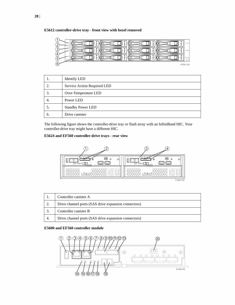
E5612 controller-drive tray - front view with bezel removed
1. Identify LED
2. Service Action Required LED
3. Over-Temperature LED
4. Power LED
5. Standby Power LED
6. Drive canister
The following figure shows the controller-drive tray or flash array with an InfiniBand HIC. Yourcontroller-drive tray might have a different HIC.
E5624 and EF560 controller-drive trays - rear view
1. Controller canister A
2. Drive channel ports (SAS drive expansion connectors)
3. Controller canister B
4. Drive channel ports (SAS drive expansion connectors)
E5600 and EF560 controller module
28 |

1. USB connector 11. SAS Expansion Link 2 Fault LED
2. 1GbE management connector 1 12. SAS Expansion Link 2 Up LED
3. 1GbE Link 1 Fault LED 13. SFF-8088 SAS connector 2 (expansion)
4. 1GbE Link 1 Up LED 14. Standby Power LED
5. 1GbE Link 2 Fault LED 15. Power-Fan DC Power LED
6. 1GbE Link 2 Up LED 16. Power-Fan Service Action Allowed LED
7. GbE management connector 2 17. Power-Fan Service Action Required LED
8. SAS Expansion Link 1 Fault LED 18. Power-Fan AC Power LED
9. SAS Expansion Link 1 Up LED 19. Seven-segment display
10. SFF-8088 SAS connector 1 (expansion) 20. Serial port
Right, rear subplate with a SAS-2 HIC
1. SFF-8088 HIC connector 1 8. SFF-8088 HIC connector 3
2. Mini-SAS Port 1 Link Fault LED 9. Mini-SAS Port 3 Link Fault LED
3. Mini-SAS Port 1 Link Up LED 10. Mini-SAS Port 3 Link Up LED
4. SFF-8088 HIC connector 2 11. SFF-8088 HIC connector 4
5. Mini-SAS Port 2 Link Fault LED 12. Mini-SAS Port 4 Link Fault LED
6. Mini-SAS Port 2 Link Up LED 13. Mini-SAS Port 4 Link UP LED
7. Serial port
Component locations | 29

Right, rear subplate with a SAS-3 HIC
1. Port 1 Link Fault LED 8. Port 3 Link Up LED
2. Port 1 Link Up LED 9. SFF-8644 HIC connector 3
3. SFF-8644 HIC connector 1 10. Serial Port
4. SFF-8644 HIC connector 2 11. SFF-8644 HIC connector 4
5. Port 2 Link Fault LED 12. Port 4 Link Fault LED
6. Port 2 Link Up LED 13. Port 4 Link Up LED
7. Port 3 Link Fault LED
Right, rear subplate with a 40-Gb InfiniBand HIC
1. HIC QSFP channel 1
2. HIC Logical Link 1 Active LED
3. HIC Physical Link 1 Active LED
4. Serial port
5. HIC Logical Link 2 Active LED
6. HIC Physical Link 2 Active LED
7. HIC QSFP channel 2
30 |

Right, rear subplate with a 56-Gb InfiniBand HIC
1. HIC QSFP channel 1
2. HIC Logical Link 1 Active LED
3. HIC Physical Link 1 Active LED
4. Serial port
5. HIC Logical Link 2 Active LED
6. HIC Physical Link 2 Active LED
7. HIC QSFP channel 2
Right, rear subplate with a 16-Gb FC or a 10-Gb iSCSI HIC
1. SFP+ HIC channel 1 8. HIC Link 3 Fault LED
2. HIC Link 1 Fault LED 9. HIC Link 3 Active LED
3. HIC Link 1 Active LED 10. Serial port
4. SFP+ HIC channel 2 11. HIC Link 4 Fault LED
5. HIC Link 2 Fault LED 12. HIC Link 4 Active LED
6. HIC Link 2 Active LED 13. SFP+ HIC channel 4
7. SFP+ HIC channel 3
Component locations | 31

Component locations on the E2800 controller shelves andthe EF280 flash arrays
The E2800 controller shelves include the E2812, E2824, E2860, and EF280. The componentlocations are identical for the E2824 controller and the EF280 flash array. However, the EF280controller supports only SSD drives.
The E2812 controller shelf has twelve 3.5 in. drive bays. The E2824 controller shelf and EF280 flasharray have twenty-four 2.5 in. drive bays. With either drive configuration, the controller shelf isavailable in two controller configurations: simplex (single controller) and duplex (two controllers).
The E2860 controller shelf has five drawers. Each drawer has twelve 3.5 in. drive bays. The E2860 isavailable only in the duplex configuration.
Keep these points in mind when you compare the figures in this section to your hardware:
• The top of the controller shelf is the side with the labels.
• The configuration of the host ports depends on which host interface card is installed.
E2812 controller shelf - front view (front bezel removed)
E2824 controller shelf and EF280 flash array - front view (front bezel removed)
E2812, E2824, EF280 controller shelf front bezel, showing LEDs on the operator display panel
1. Power
2. Attention
3. Locate
E2860 controller shelf - front view (front bezel removed)
32 |
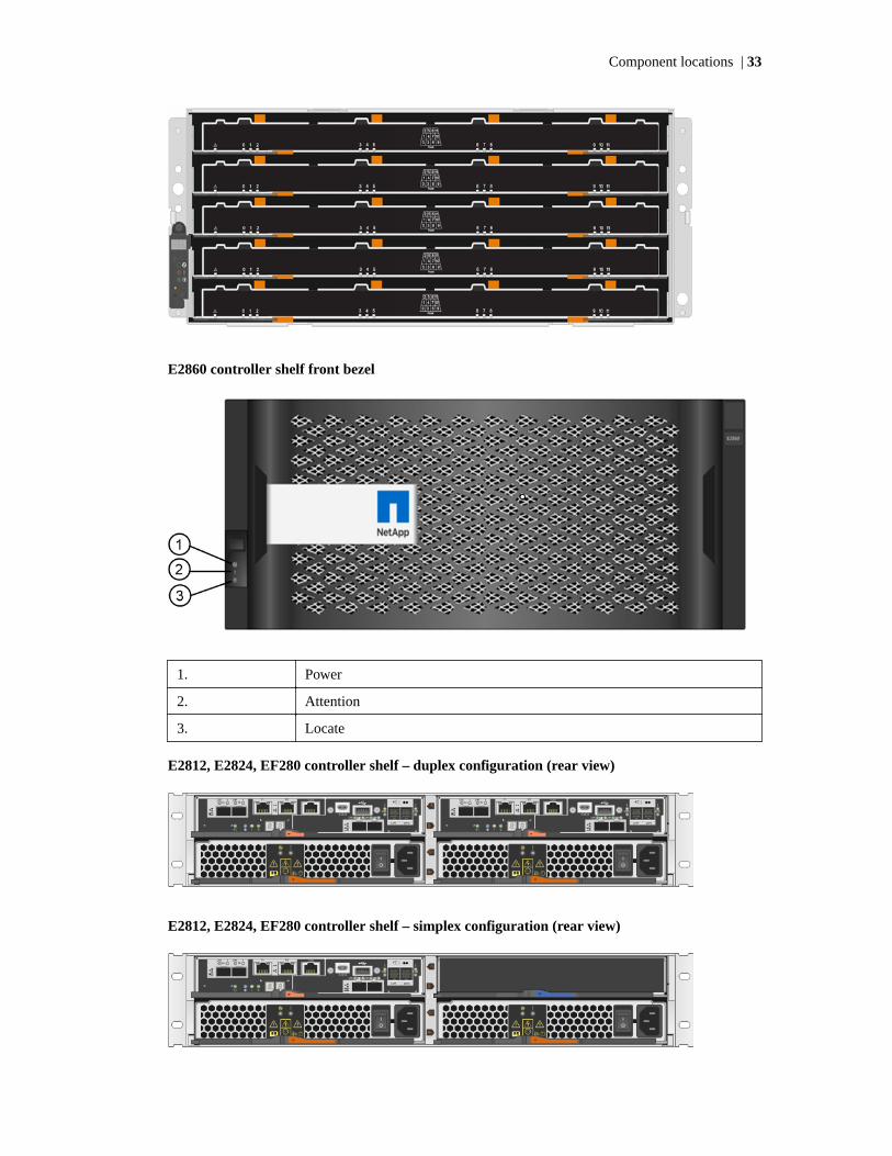
E2860 controller shelf front bezel
1. Power
2. Attention
3. Locate
E2812, E2824, EF280 controller shelf – duplex configuration (rear view)
E2812, E2824, EF280 controller shelf – simplex configuration (rear view)
Component locations | 33

E2860 controller shelf (rear view)
E2800 controller LEDs
1. Cache Active
2. Locate
3. Attention
4. Activity
5. Ethernet Status
6. Ethernet Activity
7. Expansion Port Link Status (SAS expansion port)
8. Expansion Port Attention (SAS expansion port)
9. Host Port Link Status (baseboard host port)
10. Host Port Attention (baseboard host port)
11. Host Port Link Status (HIC host port)
12. Host Port Attention (HIC host port)
34 |

E2800 controller with RJ-45 baseboard ports and no host interface card
1. Two baseboard host ports – 10 Gb/s iSCSI
E2800 controller with RJ-45 baseboard ports and a dual-port RJ-45 host interface card
1. Two baseboard host ports –10 Gb/s iSCSI
2. Two HIC ports –10 Gb/s iSCSI
E2800 controller with SFP baseboard ports and no host interface card
1. Two baseboard host ports –16 Gb/s FC or 10 Gb/s iSCSI
E2800 controller with SFP baseboard ports and a dual-port SAS host interface card
1. Two baseboard host ports –16 Gb/s FC or 10 Gb/s iSCSI
Component locations | 35
2. Two HIC ports – 12 Gb/s SAS
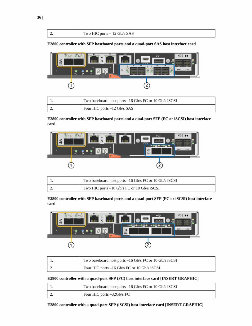
E2800 controller with SFP baseboard ports and a quad-port SAS host interface card
1. Two baseboard host ports –16 Gb/s FC or 10 Gb/s iSCSI
2. Four HIC ports –12 Gb/s SAS
E2800 controller with SFP baseboard ports and a dual-port SFP (FC or iSCSI) host interfacecard
1. Two baseboard host ports –16 Gb/s FC or 10 Gb/s iSCSI
2. Two HIC ports –16 Gb/s FC or 10 Gb/s iSCSI
E2800 controller with SFP baseboard ports and a quad-port SFP (FC or iSCSI) host interfacecard
1. Two baseboard host ports –16 Gb/s FC or 10 Gb/s iSCSI
2. Four HIC ports –16 Gb/s FC or 10 Gb/s iSCSI
E2800 controller with a quad-port SFP (FC) host interface card [INSERT GRAPHIC]
1. Two baseboard host ports –16 Gb/s FC or 10 Gb/s iSCSI
2. Four HIC ports –32Gb/s FC
E2800 controller with a quad-port SFP (iSCSI) host interface card [INSERT GRAPHIC]
36 |

1. Two baseboard host ports –16 Gb/s FC or 10 Gb/s iSCSI
2. Four HIC ports –10Gb/s or 25 Gb/s GE iSCSI
Component locations on the E2700 controller-drive traysThe E2712 controller-drive tray has twelve 3.5-in. drive bays. The E2724 controller-drive tray hastwenty-four 2.5-in. drive bays. With either drive configuration, the controller-drive tray is available intwo different controller configurations: simplex (one controller) and duplex (two controllers). TheE2760 controller-drive tray is available only in the duplex configuration.
Keep these points in mind when you compare the figures in this section to your hardware:
• The top of the controller-drive tray is the side with the labels.
• The configuration of the host ports depends on which host interface card configuration isinstalled.
• The figures in this section show the AC power option.
E2712 controller-drive tray - front view
98006-06
!
1 2 3 4 5 6
1. Standby Power LED
2. Power LED
3. Over-Temperature LED
4. Service Action Required LED
5. Locate LED
6. Drive Canister
Component locations | 37
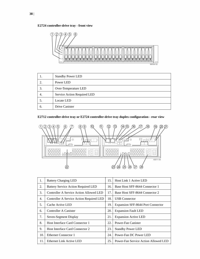
E2724 controller-drive tray - front view
1. Standby Power LED
2. Power LED
3. Over-Temperature LED
4. Service Action Required LED
5. Locate LED
6. Drive Canister
E2712 controller-drive tray or E2724 controller-drive tray duplex configuration - rear view
1. Battery Charging LED 15. Host Link 1 Active LED
2. Battery Service Action Required LED 16. Base Host SFF-8644 Connector 1
3. Controller A Service Action Allowed LED 17. Base Host SFF-8644 Connector 2
4. Controller A Service Action Required LED 18. USB Connector
5. Cache Active LED 19. Expansion SFF-8644 Port Connector
6. Controller A Canister 20. Expansion Fault LED
7. Seven-Segment Display 21. Expansion Active LED
8. Host Interface Card Connector 1 22. Power-Fan Canister
9. Host Interface Card Connector 2 23. Standby Power LED
10. Ethernet Connector 1 24. Power-Fan DC Power LED
11. Ethernet Link Active LED 25. Power-Fan Service Action Allowed LED
38 |

12. Ethernet Link Rate LED 26. Power-Fan Service Action Required LED
13. Ethernet Connector 2 27. Power-Fan AC Power LED
14. Host Link 1 Fault LED 28. AC Power Connector
E2712 controller-drive tray or E2724 controller-drive tray simplex configuration - rear view
1. Controller A Canister 8. Unused Controller B Slot
2. Seven-Segment Display 9. Power-Fan A Canister
3. Host Interface Card Connector 1 10. Standby Power LED
4. Host Interface Card Connector 2 11. Power-Fan DC Power LED
5. Expansion Fault LED 12. Power-Fan Service Action Allowed LED
6. Expansion Active LED 13. Power-Fan Service Action Required LED
7. Expansion Port SFF-8644 Connector 14. Power-Fan AC Power LED
E2760 controller-drive tray - front view
1. Drive Drawer
2. Standby Power LED
3. Power LED
4. Over-Temperature LED
Component locations | 39

5. Service Action Required LED
6. Locate LED
E2760 controller-drive tray duplex configuration - rear view
1. Fan Canister 19. Expansion Fault LED
2. Fan Power LED 20. Expansion Active LED
3. Fan Service Action Required LED 21. Expansion SFF-8644 Port Connector
4. Fan Service Action Allowed LED 22. Second Seven-Segment Display Field
5. USB Connector 23. First Seven-Segment Display Field
6. Ethernet Link 1 Active LED 24. Cache Active LED
7. Ethernet Connector 1 25. Controller A Service Action Required LED
8. Ethernet Link 1 Rate LED 26. Controller A Service Action Allowed LED
9. Ethernet Link 2 Active LED 27. Battery Service Action Required LED
10. Ethernet Connector 2 28. Battery Charging LED
11. Ethernet Link 2 Rate LED 29. Power Canister
12. Host Link 1 Fault LED 30. Power Canister AC Power LED
13. Base Host SFF-8644 Connector 1 31. Power Canister Service Required Allowed LED
14. Host Link 1 Active LED 32. Power Canister Service Action Allowed LED
15. Host Link 2 Fault LED 33. Power Canister DC Power LED
16. Host Link 2 Active LED 34. Power Canister Standby Power LED
40 |

17. Base Host SFF-8644 Connector 2
18. Controller A Cannister
E2700 right, rear subplate with no host interface card
1. Expansion Fault LED
2. Expansion Active LED
3. Expansion SFF-8644 Port Connector
E2700 right, rear subplate with a dual port SAS host interface card
1. Host Interface Link 3 Fault LED 6. SFF-8644 Host Interface Connector 4
Component locations | 41

2. Host Interface Link 3 Active LED 7. Expansion Fault LED
3. SFF-8644 Host Interface Connector 3 8. Expansion Active LED
4. Host Interface Link 4 Fault LED 9. Expansion SFF-8644 Port Connector
5. Host Interface Card Link 4 Active LED
E2700 right, rear subplate with a quad port SAS host interface card
1. Host Interface Link 3 Fault LED 6. SFF-8644 Host Interface Connector 4
2. Host Interface Link 3 Active LED 7. Expansion Fault LED
3. SFF-8644 Host Interface Connector 3 8. Expansion Active LED
4. Host Interface Link 4 Fault LED 9. Expansion SFF-8644 Port Connector
5. Host Interface Card Link 4 Active LED
42 |
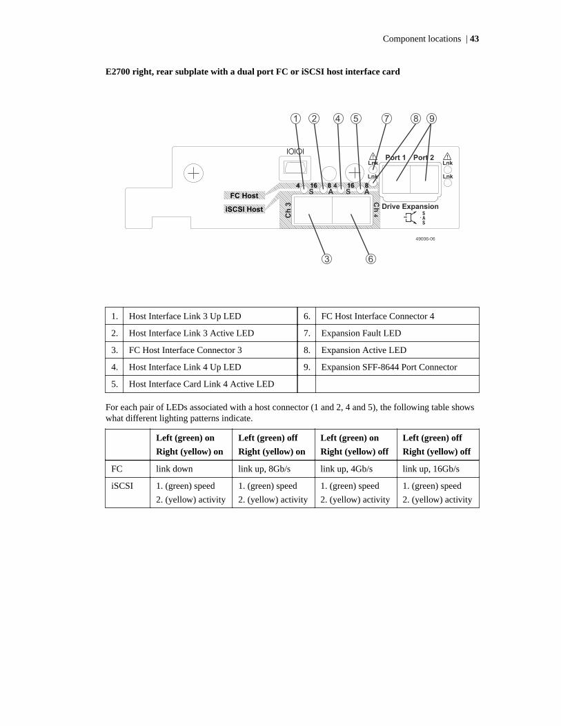
E2700 right, rear subplate with a dual port FC or iSCSI host interface card
1. Host Interface Link 3 Up LED 6. FC Host Interface Connector 4
2. Host Interface Link 3 Active LED 7. Expansion Fault LED
3. FC Host Interface Connector 3 8. Expansion Active LED
4. Host Interface Link 4 Up LED 9. Expansion SFF-8644 Port Connector
5. Host Interface Card Link 4 Active LED
For each pair of LEDs associated with a host connector (1 and 2, 4 and 5), the following table showswhat different lighting patterns indicate.
Left (green) on
Right (yellow) on
Left (green) off
Right (yellow) on
Left (green) on
Right (yellow) off
Left (green) off
Right (yellow) off
FC link down link up, 8Gb/s link up, 4Gb/s link up, 16Gb/s
iSCSI 1. (green) speed
2. (yellow) activity
1. (green) speed
2. (yellow) activity
1. (green) speed
2. (yellow) activity
1. (green) speed
2. (yellow) activity
Component locations | 43
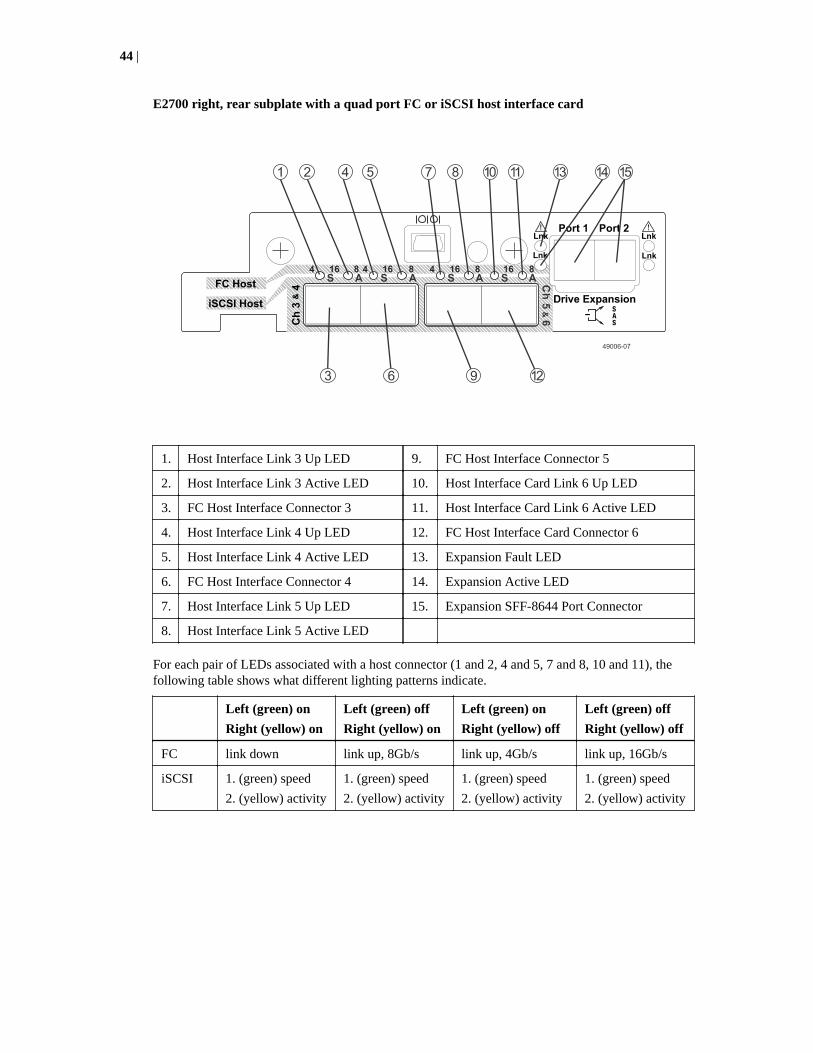
E2700 right, rear subplate with a quad port FC or iSCSI host interface card
1. Host Interface Link 3 Up LED 9. FC Host Interface Connector 5
2. Host Interface Link 3 Active LED 10. Host Interface Card Link 6 Up LED
3. FC Host Interface Connector 3 11. Host Interface Card Link 6 Active LED
4. Host Interface Link 4 Up LED 12. FC Host Interface Card Connector 6
5. Host Interface Link 4 Active LED 13. Expansion Fault LED
6. FC Host Interface Connector 4 14. Expansion Active LED
7. Host Interface Link 5 Up LED 15. Expansion SFF-8644 Port Connector
8. Host Interface Link 5 Active LED
For each pair of LEDs associated with a host connector (1 and 2, 4 and 5, 7 and 8, 10 and 11), thefollowing table shows what different lighting patterns indicate.
Left (green) on
Right (yellow) on
Left (green) off
Right (yellow) on
Left (green) on
Right (yellow) off
Left (green) off
Right (yellow) off
FC link down link up, 8Gb/s link up, 4Gb/s link up, 16Gb/s
iSCSI 1. (green) speed
2. (yellow) activity
1. (green) speed
2. (yellow) activity
1. (green) speed
2. (yellow) activity
1. (green) speed
2. (yellow) activity
44 |

E2700 right, rear subplate with a 1-Gb/s iSCSI host interface card
1. Host Interface Link 3 Up LED 6. iSCSI Host Interface Connector 4
2. Host Interface Link 3 Active LED 7. Expansion Fault LED
3. iSCSI Host Interface Connector 3 8. Expansion Active LED
4. Host Interface Link 4 Up LED 9. Expansion SFF-8644 Port Connector
5. Host Interface Card Link 4 Active LED
Component locations on the DE460C drive shelf
The DE460C drive shelf has five drawers. Each drawer has twelve 2.5 in. drive bays. The front viewand the location of LEDs on the operator display panel are the same as for the E2860 controllershelves.
DE460C drive shelf - rear view
1. I/O modules (IOMs)
Component locations | 45

DE460C drive shelf - IOM LEDs
1. SAS port Attention
2. IOM Attention
3. Locate
4. SAS port Link Status
Component locations on the DE6600 drive shelf (drive tray)
DE6600 drive shelf - front view with the bezel in place
46 |
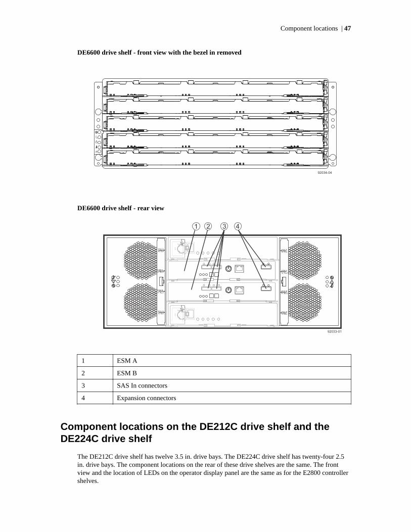
DE6600 drive shelf - front view with the bezel in removed
DE6600 drive shelf - rear view
1 ESM A
2 ESM B
3 SAS In connectors
4 Expansion connectors
Component locations on the DE212C drive shelf and theDE224C drive shelf
The DE212C drive shelf has twelve 3.5 in. drive bays. The DE224C drive shelf has twenty-four 2.5in. drive bays. The component locations on the rear of these drive shelves are the same. The frontview and the location of LEDs on the operator display panel are the same as for the E2800 controllershelves.
Component locations | 47

DE212C drive shelf or DE224C drive shelf - rear view
1. I/O modules (IOMs)
DE212C or DE224C drive shelf - IOM LEDs
1. SAS Port Attention
2. IOM Attention
3. SAS Port Attention
4. Shelf Locate
Component locations on the DE1600 drive shelf (drive tray)and the DE5600 drive shelf (drive tray)
The DE1600 drive shelf has twelve 3.5 in. drive bays. The DE5600 drive shelf has twenty-four 2.5 in.drive bays. The component locations on the rear of these drive shelves are the same. The followingfigures show the AC power option.
48 |

DE1600 drive shelf - front view
1. Left end cap (Has the drive shelf LEDs)
2. Drives
3. Right end cap
DE5600 drive shelf - front view
1. Left end cap (Has the drive shelf LEDs)
2. Drives
3. Right end cap
DE1600 drive shelf or DE5600 drive shelf - rear view
1. ESM A canister 7. Expansion port SFF-8088 connector
Component locations | 49

2. SAS In connector 1 8. Power-fan canister
3. SAS In connector 2 9. Power connector
4. Seven-segment display indicators 10. Power switch
5. Serial connector 11. ESM B canister
6. Ethernet connector
50 |
Host cabling
This chapter provides examples of cabling topologies between one or more hosts and a controllershelf or controller-drive tray. Direct-attach topologies, fabric topologies, and mixed topologies areaddressed.
You have several options for cabling between one or more hosts and a controller shelf or controller-drive tray. Options include direct-attach topologies, fabric topologies, and mixed topologies. Theexamples provided in this chapter show basic concepts to help you define an optimal host-cablingtopology. You are not limited to using only these topologies. A table that lists the maximumsupported number of hosts is included.
For host port locations on the specific controller shelf or controller-drive tray model that you areinstalling, see Component locations on page 22.
Note: If you are using the Synchronous Mirroring feature or the Asynchronous Mirroring feature,see Hardware installation for Synchronous Mirroring and Asynchronous Mirroring on page 110for information on cabling for these features.
Host interface connectionsEach controller in an E5700 controller shelf (E5724 and E5760) or EF570 flash array has thefollowing options for built-in (base) ports:
• Dual 10-Gb/s iSCSI connections (optical)
• Dual 16-Gb/s Fibre Channel connections (optical)
Each controller in an E5700 also might have an optional HIC installed.
The E5600 controller-drive trays (E5612, E5624, and E5660) and the EF560 flash array connect tohosts through one HIC on each controller.
Each controller in an E2800 controller shelf (E2812, E2824, or E2860) or EF280 flash array have oneof the following options for built-in (base) ports:
• Dual RJ-45 ports for 1-Gb/s or 10-Gb/s iSCSI connection
• Dual SFP ports that can be configured for 1-Gb/s or 10-Gb/s iSCSI connections or for 4-Gb/s, 8-Gb/s or 16-Gb/s Fibre Channel connections
Each controller in an E2800 controller shelf also might have an optional HIC installed.
Each controller in an E2700 controller-drive tray (E2712, E2724, or E2760) has built-in (base) SASconnectors for host connections and might also have an optional HIC installed
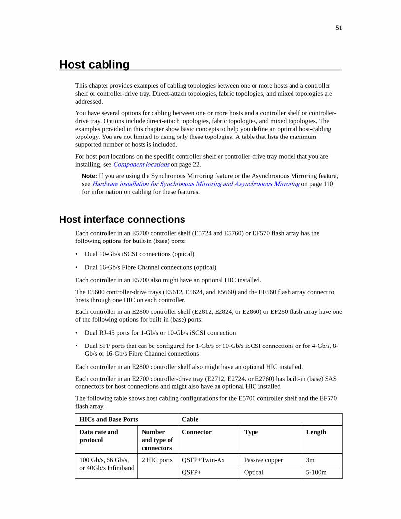
The following table shows host cabling configurations for the E5700 controller shelf and the EF570flash array.
HICs and Base Ports Cable
Data rate andprotocol
Numberand type ofconnectors
Connector Type Length
100 Gb/s, 56 Gb/s,or 40Gb/s Infiniband
2 HIC ports QSFP+Twin-Ax Passive copper 3m
QSFP+ Optical 5-100m
51

HICs and Base Ports Cable
Data rate andprotocol
Numberand type ofconnectors
Connector Type Length
32 Gb/s, 16 Gb/s, or8 Gb/s FibreChannel
4 HIC ports SFP+ OM2 optical 2,3,5,10,25m
OM3 optical 50-100m
OM4 optical 1,2,3,4,5m
25 Gb/s, or 10 Gb/siSCSI
4 HIC ports SFP28 OM3 optical 1-30m
OM4 optical 1,2,3,5,7m
SFP28 with Twin-Ax
Passive copper Up to 3m
SFP+ OM2 optical 1-25m
OM3 optical 25-300m
OM4 optical 1,2,3,5,7m
SFP+ Twin-Ax Passive Copper Up to 5m
12 Gb/s, 6 Gb/s, or 3Gb/s SAS
4 HIC ports MiniSAS-HD Passive copper 1-5m
2m
Active optical 20-100m
MiniSAS Passive copper 1-5m
16 Gb/s, 8 Gb/s, or 4Gb/s Fibre Channel
2 base ports SFP+ OM2 SW optical 1,2,3,5,10,25m
OMW3 SW optical 50-100m
OM4 optical 1,2,3,4,5m
10 Gb/s or 1 Gb/siSCSI
2 base ports SFP+ OM2 optical 1,2,3,10,25m
OM3 optical 25-300m
OM4 optical 1,2,3,4,5m
Twin-Ax (DAC) Passive cooper 2-7m
1 Gb/s iSCSI 2 base ports RJ-45 Cat6 passive copper Up to 70m
Note: The E5700 controller shelf does not support bifurcated SAS cable configurations.
The following table shows host cabling configurations for the E5600 controller-drive trays and theEF560 flash arrays.
52 |

HIC Cable
Data rate andprotocol
Number ofconnectors
Connector Type Length
12 Gb/s SAS 4 MiniSAS-HD passive copper 1-5m
MiniSAS-HD optical 5-100m
Fan-out cable type#2
passive copper 2m
Fan-out cable type#3
passive copper 2m
6 Gb/s SAS 4 MiniSAS passive copper 1-10m
Fan-out cable type#1
passive copper 2m
56 Gb/s InfiniBand1 2 QSFP+ passive copper 1-3m
QSFP+ optical 5-100m
40 Gb/s InfiniBand2 2 QSFP+ passive copper 1-5m
QSFP+ optical 10-300m
16 Gb/s FibreChannel
4 SFP+ OM2 SW optical 2, 3, 5, 10,25m
SFP+ OM3 SW optical 50-150m
SFP+ OS2 LW optical 50-300m
10 Gb/s iSCSI 4 SFP+ OM2 optical 2, 3, 5, 10,25m
SFP+ OM3 optical 50-150m
Twin-Ax passive copper 2-7m
1 Gb/s iSCSI 4 SFP+3 OM2 optical 2, 3, 5, 10,25m
SFP+3 OM3 optical 50-150m
Twin-Ax passive copper 2-7m
RJ-454 passive copper 2-70m
1This information applies to HICs with a maximum data rate of 56 Gb/s. These HICs can also beoperated at 40 Gb/s.2This information applies to HICs with a maximum data rate of 40 Gb/s. These HICs can also beoperated at 20 Gb/s. Use these HICs only in the E5500 and EF550 models.3Optical cables for 1-Gb/s iSCSI connections require a 1-Gb/s SFP.4 Copper cables with RJ-45 connectors for iSCSI connections require an SFP adapter.
The following table shows host cabling configurations for the E2800 controller shelf.
Host cabling | 53

HICs and base ports Cable
Data rate andprotocol
Numberand type ofconnectors
Connector Type Length
12 Gb/s SAS or
6 Gb/s SAS
4 or 2 HICports
MiniSAS-HD passive copper 1-5m
MiniSAS-HD optical 5-100m
Fan-out cable type#3
passive copper 2m
6 Gb/s SAS only 4 or 2 HICports
Fan-out cable type#2
passive copper 2m
16 Gb/s, 8 Gb/s, or 4Gb/s Fibre Channel
4 or 2 HICoptical ports
SFP+ OM2 SW optical 2,3,5,10,25m
SFP+ OM3 SW optical 50-100m
2 baseoptical ports
SFP+ OM2 SW optical 2,3,5,10,25m
SFP+ OM3 SW optical 50-100m
SFP+ OS1 LW optical 50-300m
10 Gb/s iSCSI or
1 Gb/s iSCSI
4 HICoptical ports
SFP+ OM2 optical 2,3,5,10,25m
SFP+ OM3 optical 50-300m
Twin-Ax (DAC) passive copper 2-7m
2 baseoptical ports
SFP+ OM2 optical 2,3,5,10,25m
Twin-Ax (DAC) passive copper 2-7m
2 base RJ-45ports
RJ-45 Cat6a passive copper 2-100m
2 HICoptical ports
SFP+ OM2 optical 2,3,5,10,25m
SFP+ OM3 optical 50-300m
Twin-Ax (DAC) passive copper 2-7m
2 HIC RJ-45ports
RJ-45 Shielded Cat6apassive copper
2-100m
1 Gb/s iSCSI only 4 HICoptical ports
RJ-45 with 1 Gb/sSFP
Cat5 passive copper 2-100m
2 HICoptical ports
RJ-45 with 1 Gb/sSFP
Cat5 passive copper 2-70m
The following table shows host cabling configurations for the E2700 controller-drive tray.
54 |

HIC Cable
Data rate andprotocol
Number ofconnectors
Connector Type Length
12 Gb/s SAS 4 MiniSAS-HD passive copper 1-5m
MiniSAS-HD optical 5-100m
2 MiniSAS-HD passive copper 1-5m
MiniSAS-HD optical 5-100m
4 Fan-out cable type#2
passive copper 2m
Fan-out cable type#3
passive copper 2m
16 Gb/s FibreChannel
4 SFP+ OM2 SW optical 2,3,5,10,25m
SFP+ OM3 SW optical 50-150m
SFP+ OS2 LW optical 50-300m
2 SFP+ OM2 SW optical 2,3,5,10,25m
SFP+ OM3 SW optical 50-150m
SFP+ OS2 LW optical 50-300m
10 Gb/s iSCSI 4 SFP+ OM2 optical 2,3,5,10,25m
SFP+ OM3 optical 50-150m
Twin-Ax passive copper 2-7m
2 SFP+ OM2 optical 2,3,5,10,25m
SFP+ OM3 optical 50-150m
Twin-Ax passive copper 2-7m
RJ-45 Cat6a passive copper 2-100m
1 Gb/s iSCSI 4 SFP+1 OM2 optical 2, 3, 5, 10,25m
SFP+1 OM3 optical 50-150m
Twin-Ax passive copper 2-7m
RJ-452 passive copper 2-70m
2 SFP+1 OM2 optical 2, 3, 5, 10,25m
SFP+1 OM3 optical 50-150m
Twin-Ax passive copper 2-7m
RJ-452 Cat5 passive copper 2-70m
RJ-45 Cat6a passive copper 2-100m
Host cabling | 55

HIC Cable
Data rate andprotocol
Number ofconnectors
Connector Type Length
1Optical cables for 1-Gb/s iSCSI connections require a 1-Gb/s SFP.2 Copper cables with RJ-45 connectors for iSCSI connections require an SFP adapter.
E2800, E5700, and E2700 controller shelves can have a mix of interface types. The HIC interfacemight be different from that of the base ports. The base ports on an E2800 controller shelf might beFibre Channel or iSCSI. The E5700 utilizes iSCSI or Fibre Channel base ports. The base ports on anE2700 are SAS.
You also can configure a HIC with four optical ports to have two Fibre Channel and two iSCSI ports.Each controller in a controller shelf must have the same configuration of ports and protocols.
E5600 controller-drive trays (E5612, E5624, and E5660) and EF560 flash arrays support a four-portHIC that might be configured with four Fibre Channel ports, four iSCSI ports, or with two ports forFibre Channel and two ports for iSCSI (split mode). If you have a HIC installed with all four portsconfigured for the same protocol, you can apply a feature pack in SANtricity Storage Manager toconvert the protocol of the host ports to Fibre Channel-iSCSI split mode. Unified SFPs are availablethat support both 16-Gb/s Fibre Channel and 10-Gb/s iSCSI. In split mode, ports 1 and 2 on bothHICs operate as iSCSI ports, while ports 3 and 4 on both HICs operate as Fibre Channel ports. Youcan also convert all four ports on a HIC from one protocol to the other. The following figure showsthe rear view of the E5612 controller-drive tray with two four-port HICs installed.
HIC port Before the conversion tosplit mode
After the conversion to split mode
1 16 Gb/s Fibre Channel or10 Gb/s iSCSI
10 Gb/s iSCSI
2 16 Gb/s Fibre Channel or10 Gb/s iSCSI
10 Gb/s iSCSI
3 16 Gb/s Fibre Channel or10 Gb/s iSCSI
16 Gb/s Fibre Channel
4 16 Gb/s Fibre Channel or10 Gb/s iSCSI
16 Gb/s Fibre Channel
A host can have both iSCSI and Fibre Channel adapters for connections to a storage array that has amix of host port protocols. Several restrictions apply to such configurations:
• The root boot feature is not supported for hosts with mixed connections to one storage array.
• Cluster configurations are supported for hosts with mixed connections to one storage array.
• When the host operating system is VMware, mixing connection types within a storage partition isnot supported.
56 |

• When the host operating system is Windows, mixing connection types within a storage partitionis not supported. A single server that attaches to multiple storage partitions on a single storagearray must not have any overlap in LUN number assignments given to the volumes.
• For other operating systems, mixed connection types from a host to a single storage array are notsupported.
A host port is connected to a host adapter: a host bus adapter (HBA) for Fibre Channel or SAS, a hostchannel adapter (HCA) for InfiniBand, or an Ethernet adapter for iSCSI. The host adapter in the hostmust support the same interface protocols as the type of host port to which it is connected.
Connect an 16-Gb/s Fibre Channel host port to an 16-Gb/s HBA. If the data rate for the HBA islower, the data transfer rate is at the lower rate. For instance, if you connect an 16-Gb/s FibreChannel host port to a 8-Gb/s HBA, the data transfer rate is 8 Gb/s.
Maximum number of host connections
Model Maximum number of hosts
E5700 controller shelves and EF570 flasharrays
1024
E5600 controller-drive trays and EF560 flasharrays
1024
E2800 controller shelves 256
E2700 controller-drive trays 256
Attention: Possible loss of data access – Do not use a combination of HBAs from differentvendors in the same storage area network (SAN). For the HBAs to perform correctly, use onlyHBAs from one manufacturer in a SAN.
Direct-attach topologiesThis section describes topologies that do not use switches to connect hosts to your storage array. Thehost adapters in the hosts might be HBAs for Fibre Channel or SAS, HCAs for InfiniBand, orEthernet for iSCSI. Some controller shelves (controller-drive trays) support more direct hostconnections than the examples shown. To cable more host connections, follow the pattern establishedby the examples in this section.
When a host is cabled to a duplex controller shelf, each attached host should have two host adaptersinstalled. For redundancy, connect one host adapter to controller A and the other to controller B.
Direct host connections to one controller shelf or controller-drive tray
These example configurations show HBAs as connecting points on the host. For other configurations,these connecting points might be host channel adapters (HCAs) for InfiniBand connections, Ethernetadapters for iSCSI connections, or a combination of one HBA and one iSCSI Ethernet adapter.
Attention: Possible loss of data access – You must install alternate path software or an alternatepath (failover) driver on the host to support failover in the event of an HBA, an HCA, or an iSCSIEthernet adapter failure or a host channel failure. Simplex configurations do not support failover.
The following figure shows an example of a direct-attach topology with one host and a duplexcontroller shelf (controller-drive tray).
Host cabling | 57

Controller A
HostPort 1
HostPort 2
Host/Server
HBA 1 HBA 2
74100
Controller B
HostPort 1
HostPort 2
The following table lists the redundant and non-redundant components in a direct-attachedconfiguration with one host and a controller shelf.
Component Redundancy
Host/server Non-redundant
HBA, HCA, or iSCSI Ethernet adapter Redundant
Host-to-controller cable Redundant
Controller Redundant
The following figure shows an example of a direct-attach topology with two hosts and a duplexcontroller shelf.
Note: In this example, the hosts/servers must be clustered to guarantee redundancy.
Controller A
HostPort 1
HostPort 2
Host/Server
HBA 1 HBA 2
Host/Server
HBA 1 HBA 2
74101
Controller B
HostPort 1
HostPort 2
58 |

The following table lists the redundant and non-redundant components in a direct-attachedconfiguration with one host and a controller-drive tray.
Component Redundancy
Host/server Redundant
HBA, HCA, or iSCSI Ethernet adapter Redundant
Host-to-controller cable Redundant
Controller Redundant
The following figure shows an example of a direct-attach topology with one host and a simplexcontroller shelf.
Controller A
HostPort 1
HostPort 2
Host/Server
HBA 1
74099
The following table lists the redundant and non-redundant components in a direct-attachedconfiguration with one host and a simplex controller shelf.
Component Redundancy
Host/server Non-redundant
HBA, HCA, or iSCSI Ethernet adapter Non-redundant
Host-to-controller cable Non-redundant
Controller Non-redundant
One host with direct SAS connections to four controller shelves orcontroller-drive trays
You can use a SAS fan-out cable to connect a host to multiple storage arrays.
Host cabling | 59

Attention: Possible loss of data access – You must install alternate path software or an alternatepath (failover) driver on the host to support failover in the event of a SAS HBA failure or a hostchannel failure.
The following figure shows an example of a direct-attach topology with one host and a four duplexcontroller shelves. Each controller shelf might have attached drive shelves (drive trays), but these arenot shown in the figure.
The following table lists the redundant and non-redundant components in a direct-attachedconfiguration with one host and four duplex controller-drive trays.
Component Redundant Non-redundant
Host/server (see note) Non-redundant
HIC (SAS) Redundant
Host-to-controller cables Redundant
Controllers Redundant
Switch topologiesThis section describes topologies that use switches to connect hosts to your storage array. The hostadapters in the hosts might be HBAs for Fibre Channel, HCAs for InfiniBand, or Ethernet for iSCSI.The switches must support the connection type (Fibre Channel, InfiniBand or Ethernet) used betweenthe host and the storage array.
When a host is cabled to a duplex controller shelf (controller-drive tray), each attached host shouldhave two host adapters installed. For redundancy, attach each of the host adapters to a differentswitch (or switch zone) so that one switch (or zone) connects to controller A and the other tocontroller B in the controller shelf. In the case where a host has one HBA and one iSCSI Ethernetadapter, the two connections might require two different types of switches.
60 |

Attention: Possible loss of data access – You must install alternate path software or an alternatepath (failover) driver on the host to support failover in the event of an HBA failure or a hostchannel failure. Simplex controller configurations do not support failover.
One host to a storage array
The following figure shows an example of a switch topology with one host, a controller shelf, and azoned switch. Each outlined group of ports on the switch represents a zone.
74102
Host/Server
HBA 1
Host Port 1
Controller A Controller B
Host Port 2
Host Port 2
HBA 2
Host Port 1
The following table lists the redundant and non-redundant components in a switched configurationwith one host and a controller shelf.
Component Redundant
Host/server Non-redundant
Host adapter Redundant
Host-to-controller cable Redundant
Switch Use two switches for full redundancy. A singlezoned switch is not redundant.
Controller Redundant
Two hosts to a storage array
The following figure shows an example of a switch topology with two hosts, a controller shelf, and azoned switch. Each outlined group of ports on the switch represents a zone.
Note: The hosts/servers in this example must be clustered to be redundant.
Host cabling | 61

The following table lists the redundant and non-redundant components in a switched configurationwith two hosts and a controller shelf.
Component Redundancy
Host/server (see note) Redundant
Host adapter Redundant
Host-to-controller cable Redundant
Switch Use two switches for full redundancy. A singlezoned switch is not redundant.
Controller Redundant
Two hosts and two zoned switches
The following figure shows an example of a switch topology with two hosts, a controller shelf, andtwo zoned switches. Each outlined group of ports on a switch represents a zone.
Note: The hosts/servers in this example must be clustered to be redundant.
The following table lists the redundant and non-redundant components in a switched configurationwith four hosts, a controller shelf, and two zoned switches.
62 |

Component Redundancy
Host/server (see note) Redundant
Host adapter Redundant
Host-to-controller cable Redundant
Switch Redundant
Controller Redundant
Mixed topologiesThis section describes an example host cabling configuration where a storage array connects to onehosts directly and to two other hosts through a switched fabric. The host adapters in the hosts mightbe HBAs for Fibre Channel or SAS, HCAs for InfiniBand, or Ethernet for iSCSI. The switches mustsupport the connection type (Fibre Channel, InfiniBand or Ethernet) used between the host and thestorage array.
The example in the figure identifies HBA1 and HBA2 on each host as connecting points. For otherconfigurations, these connecting points might be Ethernet adapters for iSCSI connections, or acombination of one HBA and one iSCSI Ethernet adapter.
When a host is cabled to a duplex controller shelf (controller-drive tray), each attached host shouldhave two host adapters installed. For redundancy, attach each of the host adapters to a differentswitch (or switch zone) so that one switch (or zone) connects to controller A and the other tocontroller B in the controller shelf. In the case where a host has one HBA and one iSCSI Ethernetadapter, the two connections might require two different types of switches. Redundancy for a hostthat attaches directly to a storage array requires that each host adapter attach to a different controller.
Attention: Possible loss of data access – You must install alternate path software or an alternatepath (failover) driver on the host to support failover in the event of an HBA failure or a hostchannel failure.
Note: The hosts/servers in this example must be clustered to be redundant.
Host cabling | 63

74104
Controller A
HostPort 1
HostPort 2
Controller B
Host/Server 1 Host/Server 2
HBA 1 HBA 2 HBA 1 HBA 2
HostPort 1
HostPort 2
Host/Server 3
HBA 1 HBA 2
The following table lists the redundant and non-redundant components in a mixed configuration withthree hosts and a controller shelf.
Component Redundant Non-redundant
Host/servers 1 and 2 Redundant
Host/server 3 Non-redundant (unless allthree hosts are in the samecluster and have similaroperating systems andadapters)
HBA or Ethernet iSCSI adapter Redundant
Host-to-controller cable Redundant
Switch Redundant
Controller Redundant
64 |

Drive shelf or drive tray cabling
A controller shelf (controller-drive tray) along with any drive shelves (drive trays) that are attached toit, comprise a storage array. When a storage array includes drive shelves, each controller in thecontroller shelf is connected to an environmental services module (ESM) for SAS-2 connections, orto an I/O module (IOM) for SAS-3 connections in a drive shelf.
The ESMs/IOMs in drive shelves are either connected to a controller in the controller shelf or to anESM/IOM in another drive shelf. Correct drive shelf cabling is important because it affects both dataavailability and the performance of a storage array. This chapter provides examples of cablingbetween a controller shelf and one or more expansion drive shelves. See Component locations onpage 22 for figures that show the port locations on the specified controller shelf and drive shelfmodels that you are connecting.
Drive shelf (drive tray) information by modelCertain shelf specifications might affect your choice of cabling topology. Make sure that yourplanned topology is compatible with applicable specifications and restrictions.
When you mix different types of drive shelves, you must consider the total number of drive slots thatare available in the final configuration of the storage array. Your configuration must meet both thelimit on the total number of drive slots and the limits on the number of drive shelves of a givenmodel.
The maximum number of drive slots and the maximum number of drive shelves for a redundant pairof channels is the same as for a single non-redundant channel.
Each storage array must contain at least one drive. For drive trays and controller-drive trays with a60-drive capacity, each of the front four bays in each of the five drawers must have a drive installed,for a minimum of twenty drives.
Controllershelf orcontroller-drive tray
DE1600 andDE5600
DE212C,DE224C, andDE460C
DE6600 DE1600, DE5600,and DE6600
E2700 Any mixture not toexceed a total of192 drive slots or16 enclosures*
Any mixture notto exceed a totalof 192 drive slotsor 16 enclosures*
Not to exceed atotal of 180 driveslots or 3enclosures*
Any mixture not toexceed a total of192 drive slots or16 enclosures*
E2800 Any mixture not toexceed a total of180 bays or 4enclosures*
Any mixture notto exceed a totalof 180 bays or 4enclosures*
Any mixture not toexceed a total of180 bays or 4enclosures*
Any mixture not toexceed a total of180 bays or 4enclosures*
E5600 Any mixture not toexceed a total of384 drive slots or16 enclosures*
Any mixture notto exceed a totalof 384 drive slotsor 16 enclosures*
Not to exceed atotal of 360 driveslots or 6enclosures*
Any mixture not toexceed a total of384 drive slots or16 enclosures*
EF560 DE5600 only.Solid state drives(SSDs) only not toexceed 120 driveslots or 5enclosures*
Not Supported Not Supported DE5600 only.Solid state drives(SSDs) only not toexceed 120 driveslots or 5enclosures*
65

Controllershelf orcontroller-drive tray
DE1600 andDE5600
DE212C,DE224C, andDE460C
DE6600 DE1600, DE5600,and DE6600
E5700 DE5600 only. Anymixture not exceeda total of 480 totaldrives or 8enclosures
DE224C andDE460C only.Any mixture notexceed a total of480 total drivesor 8 enclosures
Any mixture not toexceed a total of480 total drives orenclosures
DE5600 andDE6600 only. Anymixture not toexceed a total of480 total drives orenclosures
EF570 DE5600 only.Solid State Drives(SSDs) only not toexceed 120 drives.
DE224C only.Solid StateDrives (SSDs)only not toexceed 120drives.
Not Supported DE5600 only.Solid State Drives(SSDs) only not toexceed 120 drives.
*Total enclosures including drive shelves and the controller shelf.
Note: The E5700 supports DE5600 and DE6600 SAS-2 enclosures via head upgrade. Whenutilizing a E5700 controller in SAS-2 enclosures, support for base host ports is disabled. Formore information on performing upgrades, refer to the E-Series Systems Controller UpgradeGuide.
Related information
E-Series System Controller Upgrade Guide
ESM module and IOM module arrangementsEach ESM has three SFF-8088 SAS ports, labeled In1, In2, and Out. Each IOM has four SFF-8644SAS ports labeled 1, 2, 3, and 4. The canisters are located adjacent to one another.
ESMs or IOMs are arranged either side-by-side or top-and-bottom depending on the enclosure type.The canisters are located adjacent to one another, as shown in the following figures.
Side-by-side ESMs in DE1600 drive shelves and DE5600 drive shelves
1. ESM A
2. SAS In - Port 1
3. SAS In - Port 2
66 |

4. SAS Out (Expansion) Port
5. ESM B
Side-by-side ESMs in DE212C drive shelves and DE224C drive shelves
1. ESM A
2. SAS Port 1
3. SAS Port 2
4. SAS Port 3
5. SAS Port 4
Stacked ESMs in DE6600 drive shelves
1. ESM A
2. ESM B
3. SAS In Ports
4. SAS In Ports
5. SAS Out (Expansion) Ports
Stacked IOMs in DE460C drive shelves
Drive shelf or drive tray cabling | 67

1 IOMs
Drive cabling topologies for the E5700 controller shelvesand the EF570 flash arrays
The E5700 controller shelf models are the E5724 and E5760. The total number of drive bays in thestorage array, including the drive bays in the controller shelf and those in the drive shelves, must notexceed 480. The total number of shelves (controller shelves and drive shelves) in a storage array mustnot exceed eight.
You can cable E5700 controller shelves to SAS-3 drives shelves (DE460C or DE224C), SAS-2 drivetrays (DE6600 or DE5600) or combinations of SAS-2 and SAS-3 drive shelves. Use cables withmini-SAS HD (SFF-8644) connectors to connect SAS-3 drive shelves. Use cables with a mini-SAS(SFF-8088) connector on one end and a mini-SAS HD connector on the other end to connect SAS-2drive shelves to the controller shelf. Use cables with a mini-SAS connector on both ends forconnections between SAS-2 drive shelves.
Note: When you install SAS cables, make sure that the blue tabs on the SAS cables face thebottom of the tray or shelf and that each connector clicks into place.
When you cable a mix of SAS-2 and SAS-3 drive shelves to the same controller shelf, you should usea dual-stack configuration. Put all of the SAS-3 drive shelves in one stack and all of the SAS-2 driveshelves in the other stack. Attach expansion port 1 from each controller to the SAS-3 stack andexpansion port two from each controller to the SAS-2 stack.
The EF570 flash array can be cabled to the DE224C drive shelves. The total number of drives in thestorage array, including the drives in the EF570 controller shelf and those in all of the attached driveshelves, must not exceed 120. The total number of trays in the storage array, including the EF570flash array and all of the attached drive trays, must not exceed five. The drive shelves must containonly solid-state disks (SSDs).
Note: When utilizing a E5700 controller in SAS-2 enclosures, support for base host ports isdisabled. For more information on performing upgrades, refer to the E-Series Systems ControllerUpgrade Guide.
Related information
E-Series System Controller Upgrade Guide
68 |
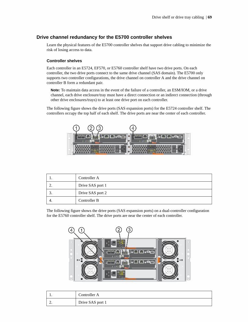
Drive channel redundancy for the E5700 controller shelves
Learn the physical features of the E5700 controller shelves that support drive cabling to minimize therisk of losing access to data.
Controller shelves
Each controller in an E5724, EF570, or E5760 controller shelf have two drive ports. On eachcontroller, the two drive ports connect to the same drive channel (SAS domain). The E5700 onlysupports two controller configurations, the drive channel on controller A and the drive channel oncontroller B form a redundant pair.
Note: To maintain data access in the event of the failure of a controller, an ESM/IOM, or a drivechannel, each drive enclosure/tray must have a direct connection or an indirect connection (throughother drive enclosures/trays) to at least one drive port on each controller.
The following figure shows the drive ports (SAS expansion ports) for the E5724 controller shelf. Thecontrollers occupy the top half of each shelf. The drive ports are near the center of each controller.
1. Controller A
2. Drive SAS port 1
3. Drive SAS port 2
4. Controller B
The following figure shows the drive ports (SAS expansion ports) on a dual-controller configurationfor the E5760 controller shelf. The drive ports are near the center of each controller.
1. Controller A
2. Drive SAS port 1
Drive shelf or drive tray cabling | 69

3. Drive SAS port 2
4. Controller B
Drive shelves
The following figures shows the SAS ports on a DE224C drive shelf. The I/O modules (IOMs)occupy the top half of the shelf. Each IOM has four SAS-3 expansion ports. You can connect theseports to SAS-3 expansion ports on another drive shelf or drive tray or to SAS expansion ports on acontroller shelf or controller drive tray.
1. IOM A
2. SAS port 1
3. SAS port 2
4. SAS port 3
5. SAS port 4
The following figure shows the SAS ports on a DE460C drive shelf. The I/O modules (IOMs) occupythe middle positions in the shelf. Each IOM has four SAS-3 expansion ports. You can connect theseports to SAS-3 expansion ports on another drive shelf or drive tray or to SAS expansion ports on acontroller shelf or controller drive tray.
1. IOM A
2. SAS port 1
3. SAS port 2
4. SAS port 3
70 |

5. SAS port 4
Drive trays
The following figures shows the SAS ports on a DE6600 or a DE5600 drive tray. Each environmentalservices module (ESM) has two SAS-2 in ports and one SAS-2 expansion (out) port. You canconnect the SAS in ports to the SAS expansion port on another drive tray or to the SAS expansionport on a controller-drive tray.
DE6600 Drive Tray
DE5600 Drive Tray
1. ESM A
2. SAS in-port 1
3. SAS in-port 2
4. SAS out (expansion) port 3
5. ESM B
Drive cabling topologies for the E5724 controller shelf and EF570 flasharray
Depending on the number and type of drive shelves that you need to connect, see the applicablefigure for a cabling topology. Each example shows a duplex controller shelf configuration withredundant paths to the drive shelves. Several options for cabling might be possible for a given driveshelf configuration.
Drive shelf or drive tray cabling | 71

One E5700 controller shelf and one SAS-3 drive shelf
One E5700 controller shelf and a single stack of SAS-3 drive shelves
72 |
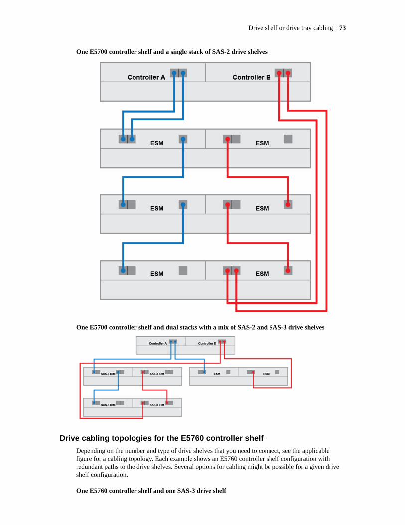
One E5700 controller shelf and a single stack of SAS-2 drive shelves
One E5700 controller shelf and dual stacks with a mix of SAS-2 and SAS-3 drive shelves
Drive cabling topologies for the E5760 controller shelf
Depending on the number and type of drive shelves that you need to connect, see the applicablefigure for a cabling topology. Each example shows an E5760 controller shelf configuration withredundant paths to the drive shelves. Several options for cabling might be possible for a given driveshelf configuration.
One E5760 controller shelf and one SAS-3 drive shelf
Drive shelf or drive tray cabling | 73

One E5760 controller shelf and a single stack of SAS-3 drive shelves
One E5760 controller shelf and a single stack of SAS-2 drive shelves
74 |

One E5760 controller shelf and dual stacks with a mix of SAS-2 and SAS-3 drive shelves
Drive tray cabling topologies for the E5600 controller-drivetrays and EF560 flash arrays
This section provides examples of drive tray cabling topologies for the E5600 (E5612, E5624,E5660) controller-drive trays and the EF560 flash array. The following table lists ports and associatedcable types and lengths.
Ports Cable
Data rate andprotocol
Number ofconnectors
Connector Type Length
Expansion:
6 Gb/s SAS
2 MiniSAS toMiniSAS
passive copper 1-5m
Drive shelf or drive tray cabling | 75

Drive channel redundancy for the E5600 controller drive trays and EF560flash arrays
Controller-drive trays
Each controller in these controller-drive trays and flash arrays has two drive expansion ports. Withthese controller-drive trays and flash arrays, you can cable a storage array so that each drive tray ordrive shelf has two drive paths to the alternate controller if a controller fails or is removed. Tomaintain data access in the event of the failure of a controller, an ESM/IOM, or a drive channel, eachESM/IOM must have a path to each controller.
Redundant path pair on the E5612 and E5624 controller drive trays and EF560 flash arrays
1. Controller canister A
2. Drive channel ports (SAS drive expansion connectors)
3. Controller canister B
4. Drive channel ports (SAS drive expansion connectors)
Redundant path pair on the E5660 controller drive trays
1. Controller canister A
2. Drive expansion ports (SAS drive expansion connectors)
3. Controller Canister B
4. Drive expansion ports (SAS drive expansion connectors)
76 |

Drive trays
The following figure shows the SAS ports on a DE1600 drive tray or a DE5600 drive tray. Eachenvironmental services module (ESM) has two SAS-2 in ports and one SAS-2 expansion (out) port.You can connect the SAS in ports to the SAS expansion port on another drive tray or to the SASexpansion port on a controller-drive tray.
1. ESM A
2. SAS in - port 1
3. SAS in - port 2
4. SAS out (expansion) port
5. ESM B
The following figures show the SAS ports on a DE6600 drive tray. Each environmental servicesmodule (ESM) has two SAS in ports and one SAS expansion (out) port. You can connect the SAS inports to the SAS expansion port on another drive tray or to the SAS expansion port on a controller-drive tray. Follow the cabling pattern shown in the figures in this topic.
1. ESM A
2. ESM B
3. SAS in ports
4. SAS out (expansion) port
Drive shelf or drive tray cabling | 77

Drive Shelves
The following figures show the SAS ports on a DE212C drive shelf or a DE224C drive shelf. The I/Omodules (IOMs) occupy the top half of the shelf. Each IOM has four SAS-3 expansion ports. Youcan connect these ports to SAS-3 expansion ports on another drive shelf or drive tray or to SASexpansion ports on a controller shelf or controller-drive tray.
1. IOM A
2. SAS port 1
3. SAS port 2
4. SAS port 3
5. SAS port 4
Drive tray cabling topologies for the E5612 and E5624 controller-drive traysand EF560 flash arrays
The figures in this section show representative cabling configurations. The configurations shownguarantee that redundant data paths exist between the controller-drive tray and all attached drive traysin a storage array. These controller-drive trays can be cabled to SAS-2 drive trays (DE1600, DE5600,and DE6600), or various combinations of those three models of drive tray. You can also cable E5612,E5624, and E5660 controller-drive trays to SAS-3 drive trays (DE212C, DE224C, and DE460C). Forany one controller-drive tray, you must not exceed the limit of 15 connected drive trays or the limitfor the total number of drive slots in the storage array.
Configurations that include SAS-3 drive trays require cables with a mini-SAS connector on one endand a mini-SAS HD connector on the other end. These cables connect between the controllers andthe SAS-3 drive trays or between SAS-2 drive trays and SAS-3 drive trays. The mini-SAS HDconnectors attach to the IOMs in the SAS-3 drive trays, while the mini-SAS connectors attach to theESMs in SAS-2 drive trays or to the controllers in the controller-drive tray. If your configuration hasa mix of SAS-2 and SAS-3 drive trays, group the SAS-3 drive trays together at the bottom or the topof the stack.
Note: The EF560 controller-drive tray can be cabled to the DE5600 drive trays only. The totalnumber of drives in the storage array, including the drives in the EF560 controller-drive tray andthose in all of the attached drive trays, must not exceed 120. The total number of trays in thestorage array, including the EF560 controller-drive tray and all of the attached drive trays, must notexceed five. The drive trays must contain only solid-state disks (SSDs).
When you cable the storage array, keep these points in mind:
• To connect an ESM/IOM to a controller-drive tray, use both of the SAS in ports on the ESM ortwo of the SAS expansion ports on an IOM. Connect one SAS in port (or SAS expansion port) toa SAS expansion port on controller A and the other SAS in port (or SAS expansion port) to a SASExpansion port on controller B in the controller-drive tray.
78 |
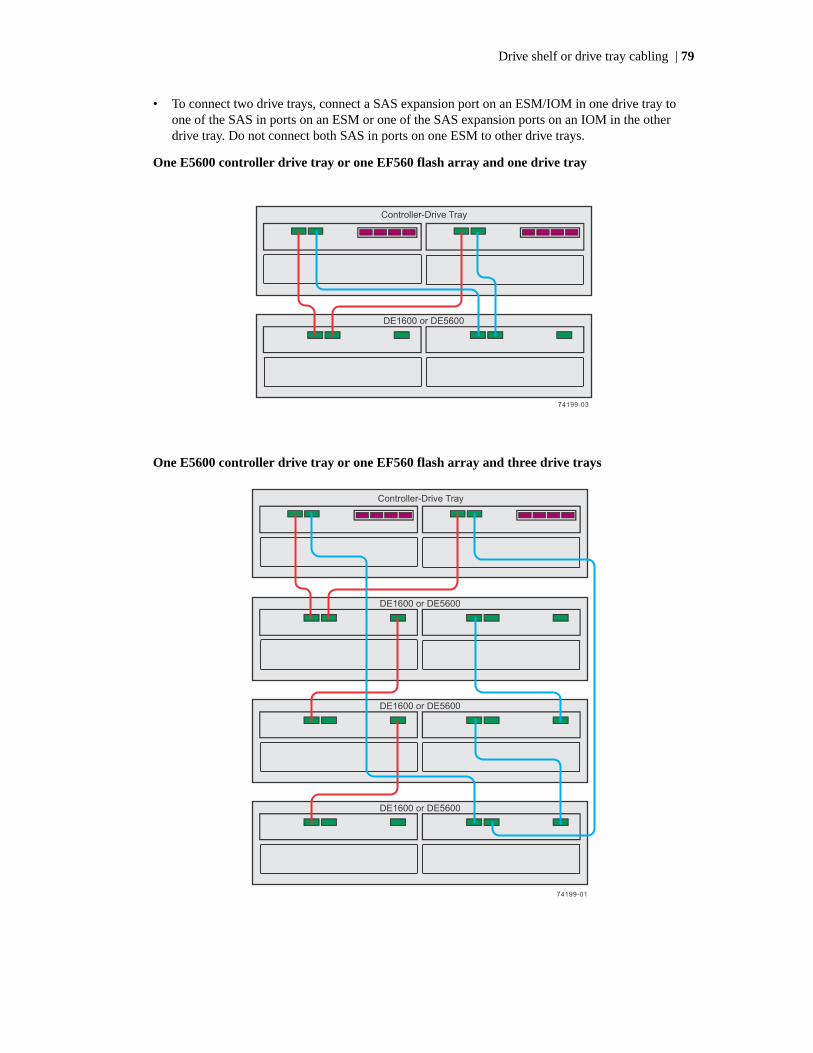
• To connect two drive trays, connect a SAS expansion port on an ESM/IOM in one drive tray toone of the SAS in ports on an ESM or one of the SAS expansion ports on an IOM in the otherdrive tray. Do not connect both SAS in ports on one ESM to other drive trays.
One E5600 controller drive tray or one EF560 flash array and one drive tray
One E5600 controller drive tray or one EF560 flash array and three drive trays
Drive shelf or drive tray cabling | 79
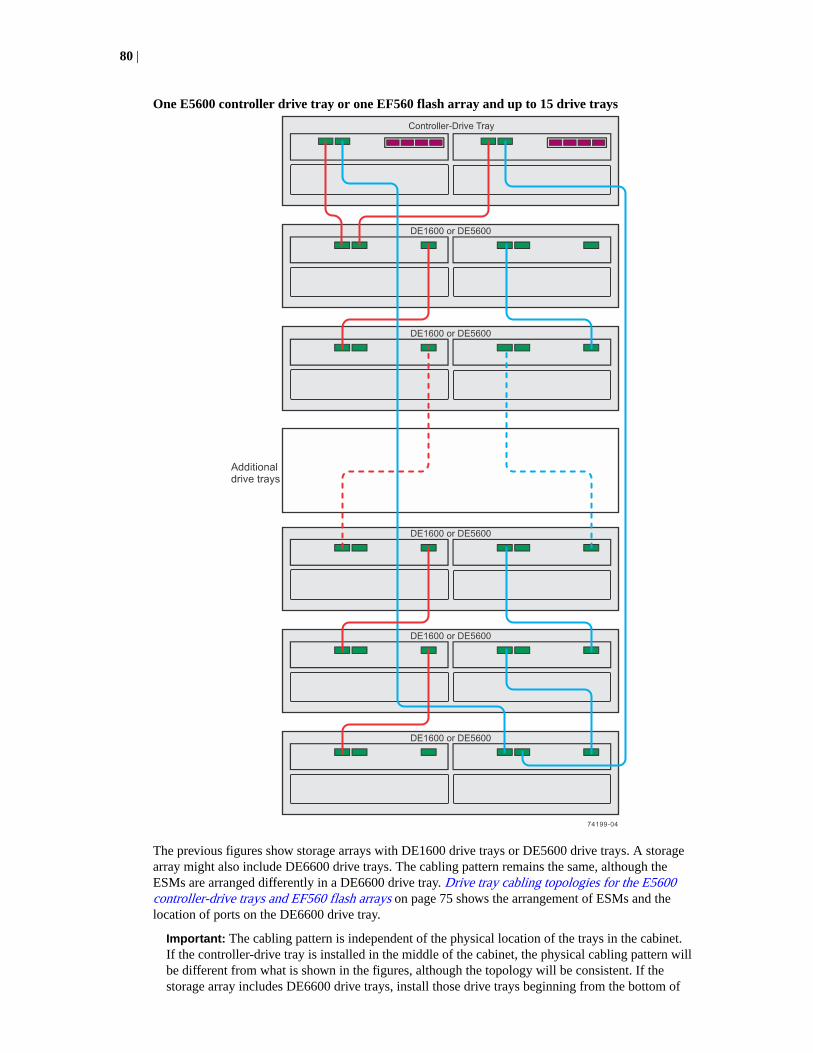
One E5600 controller drive tray or one EF560 flash array and up to 15 drive trays
The previous figures show storage arrays with DE1600 drive trays or DE5600 drive trays. A storagearray might also include DE6600 drive trays. The cabling pattern remains the same, although theESMs are arranged differently in a DE6600 drive tray. Drive tray cabling topologies for the E5600controller-drive trays and EF560 flash arrays on page 75 shows the arrangement of ESMs and thelocation of ports on the DE6600 drive tray.
Important: The cabling pattern is independent of the physical location of the trays in the cabinet.If the controller-drive tray is installed in the middle of the cabinet, the physical cabling pattern willbe different from what is shown in the figures, although the topology will be consistent. If thestorage array includes DE6600 drive trays, install those drive trays beginning from the bottom of
80 |

the cabinet so that the cabinet does not become top-heavy. A top-heavy cabinet has a greater riskof falling over.
Drive tray cabling topologies for the E5660 controller-drive tray
The figures in this section show representative cabling configurations. The configurations shownguarantee that redundant data paths exist between the controller-drive tray and all attached drive traysin a storage array. These controller-drive trays can be cabled to SAS2 drive trays (DE1600, DE5600,and DE6600), or various combinations of those three models of drive tray. You can cable E5660controller-drive trays to SAS3 drive trays (DE212C, DE2124C, and DE460C).
Configurations that include SAS3 drive trays require cables with a mini-SAS connector on one endand a mini-SAS HD connector on the other end. Use these cables to connect between controllers andSAS-3 drive trays or between a SAS-2 drive tray and a SAS-3 drive tray. The mini-SAS HDconnectors attach to the IOMs in the SAS3 drive trays, while the mini-SAS connectors attach to theESMs in SAS2 drive trays or to the controllers in the controller-drive tray. If your configuration has amix of SAS2 and SAS3 drive trays, group the SAS3 drive trays together at the bottom or the top ofthe stack.
Caution: Risk of bodily injury – An empty tray weighs approximately 56.7 kg (125 lb). Threepersons are required to safely move an empty tray. If the tray is populated with components, amechanized lift is required to safely move the tray.
Note: To ensure cabinet stability and guarantee the lowest possible center of gravity, install only60-drive trays (E5560 controller-drive trays, DE660 drive trays, or DE460C drive trays) at thebottom of the cabinet, and install any 12-drive trays or any 24-drive trays above all 60-drive trays,with no empty space. A top-heavy cabinet has a greater risk of falling over.
For any one controller-drive tray, you must not exceed the limit of 15 connected drive trays or thelimit for the total number of drive slots in the storage array. You are notified through the Major EventLog (MEL) if you attempt to install drive slots in excess of the limit for your storage array. Contacttechnical support if this occurs.
When you cable the storage array, keep these points in mind:
• To connect an ESM/IOM to a controller-drive tray, use both of the SAS in ports on the ESM ortwo of the SAS expansion ports on an IOM. Connect one SAS in port (or SAS expansion port) toa SAS Expansion port on controller A and the other SAS in port (or SAS expansion port) to aSAS Expansion port on controller B in the controller-drive tray.
• To connect two drive trays, connect a SAS Expansion port on an ESM/IOM in one drive tray toone of the SAS in ports on an ESM or one of the SAS expansion ports on an IOM in the otherdrive tray. Do not connect both SAS in ports on one ESM to other drive trays.
Drive shelf or drive tray cabling | 81

One E5660 controller-drive tray and one DE6600 drive tray
82 |

One E5660 controller-drive tray and five DE6600 drive trays
The figures above show storage arrays with DE6600 drive trays. A storage array with an E5660controller-drive tray might also include DE1600 drive trays or DE5600 drive trays. The cablingpattern remains the same, although the ESMs are arranged differently in DE1600 drive trays andDE5600 drive trays. Drive tray cabling topologies for the E5612 and E5624 controller-drive trays andEF560 flash arrays on page 78 shows the arrangement of ESMs and the location of ports on theDE1600 drive trays and DE5600 drive trays.
Drive shelf or drive tray cabling | 83

Drive cabling topologies for the E2800 controller shelvesand the EF280 flash array
The E2800 controller shelf models are the E2812, E2824, EF280, and E2860. The total number ofdrive bays in the storage array, including the drive bays in the controller shelf and those in the drivesshelves, must not exceed 180. The total number of shelves (controller shelves and drive shelves) in astorage array must not exceed four.
You can cable E2800 controller shelves to SAS-3 drive shelves (DE212C, DE224C, or DE460C),SAS-2 drive trays (DE1600, DE5600, or DE660) or combinations of SAS-2 and SAS-3 drive shelves.Use cables with mini-SAS HD (SFF-8644) connectors to connect SAS-3 drive shelves. Use cableswith a mini-SAS (SFF-8088) connector on one end and a mini-SAS HD connector on the other endto connect SAS-2 drive shelves to the controller shelf. Use cables with a mini-SAS connector on bothends for connections between SAS-2 drive shelves. The EF280 flash array can be cabled to theDE224C drive shelves.
Note: When you install SAS cables, make sure that the blue tabs on the SAS cables face thebottom of the tray or shelf and that each connector clicks into place.
Note: Simplex systems do not provide redundant connections to drive shelves. If a connection oran IOM fails, all drive shelves that connect to the controller shelf indirectly through the failedconnection or drive shelf become inaccessible.
When you cable a mix of SAS-2 and SAS-3 drive shelves to the same controller shelf, you should usea dual-stack configuration. Put all of the SAS-3 drive shelves in one stack and all of the SAS-2 driveshelves in the other stack. Attach expansion port 1 from each controller to the SAS-3 stack andexpansion port two from each controller to the SAS-2 stack.
Drive channel redundancy for the E2800 controller shelves
Learn the physical features of the E2800 controller shelves that support drive cabling to minimize therisk of losing access to data.
Controller shelves
Each controller in an E2812, E2824, EF280, or E2860 controller shelf has two drive ports. On eachcontroller, the two drive ports connect to the same drive channel (SAS domain). When a controllershelf has two controllers, the drive channel on controller A and the drive channel on controller Bform a redundant pair.
Note: To maintain data access in the event of the failure of a controller, an ESM/IOM, or a drivechannel, each drive tray must have a direct connection or an indirect connection (through otherdrive trays) to at least one drive port on each controller in a dual-controller configuration.
The following figure shows the drive ports (SAS expansion ports) on a dual-controller configurationfor the E2812, EF280, or E2824 controller shelf. The controllers occupy the top half of each shelf.The drive ports are at the far right of each controller.
84 |

1. Controller A
2. SAS port 1
3. SAS port 2
4. Controller B
The following figure shows the drive ports (SAS expansion ports) on a dual-controller configurationfor the E2860 controller shelf. The drive ports are at the far right of each controller.
1. Controller A
2. Controller B
3. SAS port 1
4. SAS port 2
Drive shelves
The following figures show the SAS ports on a DE212C drive shelf or a DE224C drive shelf. The I/Omodules (IOMs) occupy the top half of the shelf. Each IOM has four SAS-3 expansion ports. Youcan connect these ports to SAS-3 expansion ports on another drive shelf or drive tray or to SASexpansion ports on a controller shelf or controller-drive tray.
1. IOM A
2. SAS port 1
3. SAS port 2
4. SAS port 3
5. SAS port 4
The following figure shows the SAS ports on a DE460C drive shelf. The I/O modules (IOMs) occupythe middle positions in the shelf Each IOM has four SAS-3 expansion ports. You can connect these
Drive shelf or drive tray cabling | 85

ports to SAS-3 expansion ports on another drive shelf or to SAS expansion ports on a controllershelf.
1. IOM A
2. SAS port 1
3. SAS port 2
4. SAS port 3
5. SAS port 3
Drive trays
The following figure shows the SAS ports on a DE1600 drive tray or a DE5600 drive tray. Eachenvironmental services module (ESM) has two SAS-2 in ports and one SAS-2 expansion (out) port.You can connect the SAS in ports to the SAS expansion port on another drive tray or to the SASexpansion port on a controller-drive tray.
1. ESM A
2. SAS in - port 1
3. SAS in - port 2
4. SAS out (expansion) port
5. ESM B
The following figures show the SAS ports on a DE6600 drive tray. Each environmental servicesmodule (ESM) has two SAS in ports and one SAS expansion (out) port. You can connect the SAS inports to the SAS expansion port on another drive tray or to the SAS expansion port on a controller-drive tray. Follow the cabling pattern shown in the figures in this topic.
86 |
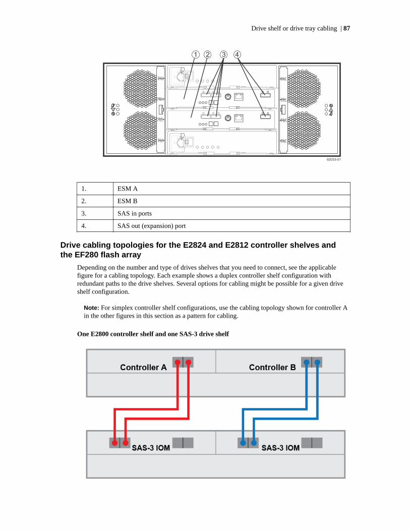
1. ESM A
2. ESM B
3. SAS in ports
4. SAS out (expansion) port
Drive cabling topologies for the E2824 and E2812 controller shelves andthe EF280 flash array
Depending on the number and type of drives shelves that you need to connect, see the applicablefigure for a cabling topology. Each example shows a duplex controller shelf configuration withredundant paths to the drive shelves. Several options for cabling might be possible for a given driveshelf configuration.
Note: For simplex controller shelf configurations, use the cabling topology shown for controller Ain the other figures in this section as a pattern for cabling.
One E2800 controller shelf and one SAS-3 drive shelf
Drive shelf or drive tray cabling | 87

One E2800 controller shelf and a single stack of SAS-3 drive shelves
One E2800 controller shelf and a single stack of SAS-2 drive shelves
88 |

One E2800 controller shelf and dual stacks with a mix of SAS-2 and SAS-3 drive shelves
Drive cabling topologies for the E2860 controller shelf
Depending on the number and type of drive shelves that you need to connect, see the applicablefigure for a cabling topology. Each example shows an E2860 controller shelf configuration withredundant paths to the drive shelves. Several options for cabling might be possible for a given driveshelf configuration.
One E2860 controller shelf and one SAS-3 drive shelf
One E2860 controller shelf and a single stack of SAS-3 drive shelves
Drive shelf or drive tray cabling | 89
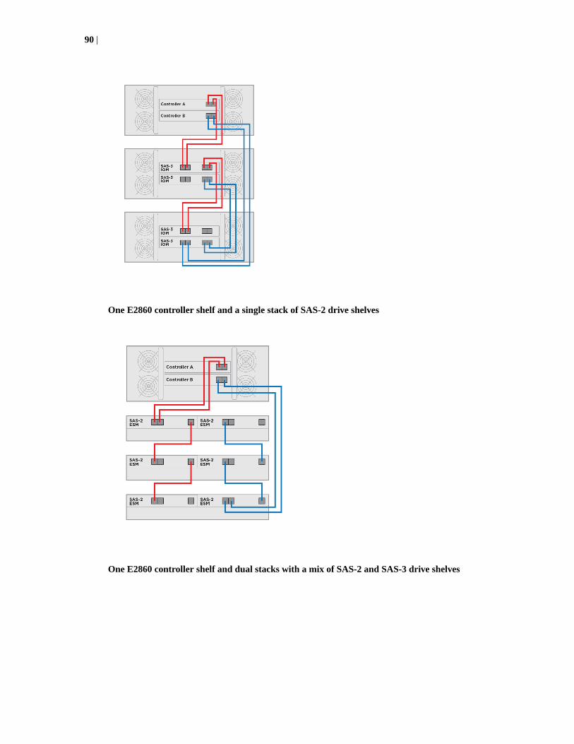
One E2860 controller shelf and a single stack of SAS-2 drive shelves
One E2860 controller shelf and dual stacks with a mix of SAS-2 and SAS-3 drive shelves
90 |

Drive tray cabling topologies for the E2700 controller-drivetrays
This section provides examples of drive tray cabling topologies for the E2700 controller-drive trays.The E2700 controller-drive tray models are: the E2712, the E2724 and the E2760. The total numberof drive slots in the storage array, including the drive slots in the controller-drive tray and those in thedrive trays, must not exceed 192.
Note: Simplex systems do not provide redundant connections to drive trays. If a connection or anenvironmental services module (ESM) fails, all drive trays that connect to the controller-drive trayindirectly through the failed connection or drive tray becomes inaccessible.
Drive channel redundancy for the E2700 controller-drive trays
Learn the physical features of the E2700 controller trays that support drive cabling to minimize therisk of losing access to data.
Controller-drive trays
Each controller in an E5712, E2724, or E2760 controller-drive tray has two drive ports. On eachcontroller, the two drive ports connect to the same drive channel (SAS domain). When a controller-drive tray has two controllers, the drive channel on controller A and the drive channel on controller Bform a redundant pair.
Note: To maintain data access in the event of the failure of a controller, an ESM/IOM, or a drivechannel, each drive tray must have a direct connection or an indirect connection (through otherdrive trays) to at least one drive port on each controller in a dual-controller configuration.
The following figure shows the drive ports on a dual-controller configuration.
Redundant path pairs on the E2712 and E2724 controller-drive trays
49006-01
1 2 1 2
ACDC ! ACDC !
Drive shelf or drive tray cabling | 91

1. Controller Canisters
2. Drive Expansion Connectors
Redundant path pairs on the E2760 controller-drive tray
49007-01
1 3
2 4
1. Controller A
2. Controller B
3. SAS Drive Expansion Connector
4. SAS Drive Expansion Connector
Drive trays
The following figure shows the SAS ports on a DE1600 drive tray or a DE5600 drive tray. Eachenvironmental services module (ESM) has two SAS-2 in ports and one SAS-2 expansion (out) port.You can connect the SAS in ports to the SAS expansion port on another drive tray or to the SASexpansion port on a controller-drive tray.
1. ESM A
2. SAS in - port 1
3. SAS in - port 2
4. SAS out (expansion) port
5. ESM B
92 |

The following figures show the SAS ports on a DE6600 drive tray. Each environmental servicesmodule (ESM) has two SAS in ports and one SAS expansion (out) port. You can connect the SAS inports to the SAS expansion port on another drive tray or to the SAS expansion port on a controller-drive tray. Follow the cabling pattern shown in the figures in this topic.
1. ESM A
2. ESM B
3. SAS in ports
4. SAS out (expansion) port
Drive shelves
The following figures show the SAS ports on a DE212C drive shelf or a DE224C drive shelf. The I/Omodules (IOMs) occupy the top half of the shelf. Each IOM has four SAS-3 expansion ports. Youcan connect these ports to SAS-3 expansion ports on another drive shelf or drive tray or to SASexpansion ports on a controller shelf or controller-drive tray.
1. IOM A
2. SAS port 1
3. SAS port 2
4. SAS port 3
5. SAS port 4
Drive shelf or drive tray cabling | 93

Drive tray cabling topologies for the E2712 controller-drive tray and theE2724 controller-drive tray
Depending on the number of drive trays that you need to connect, see the applicable figure for acabling topology. Each example shows a duplex controller-drive tray configuration with redundantpaths to the drive trays. Several options for cabling might be possible for a given drive trayconfiguration. You should cable both expansion ports on each controller for improved performancewhen two controllers are used.
Dual-stack cabling is recommended for better performance if your storage array includes two ormore expansion drive trays. In dual-stack cabling configurations, the number of drive trays in eachstack should be as balanced as possible. Each stack should have the same number of drive trays foran even total number of drive trays or the number of drive trays in each stack should differ by one foran odd total number of drive trays. For a simplex controller-drive tray configurations, do not use thecabling pattern shown in the figure "One E2700 controller-drive tray and one drive tray(recommended cabling for improved performance)." Use the cabling topology shown for controller Ain the other figures in this section as a pattern for cabling with a simplex controller-drive tray.
These controller-drive trays can be cabled to SAS-2 drive trays (DE1600, DE5600, and DE6600), orvarious combinations of those three models of drive tray. For any one controller-drive tray, you mustnot exceed the limit of 15 connected drive trays or the limit for the total number of drive slots in thestorage array.
Note: The following figures shows the SAS ports on a DE1600 drive tray or a DE5600 drive tray.You can connect either of the SAS ports labeled SAS 1 and SAS 2 to the SAS Expansion port onanother drive tray or on a controller-drive tray.
One E2700 controller-drive tray and one drive tray (recommended cabling for improvedperformance)
94 |

One E2700 controller-drive tray and one drive tray
One E2700 controller-drive tray and two drive trays (dual stack configuration)
Drive shelf or drive tray cabling | 95
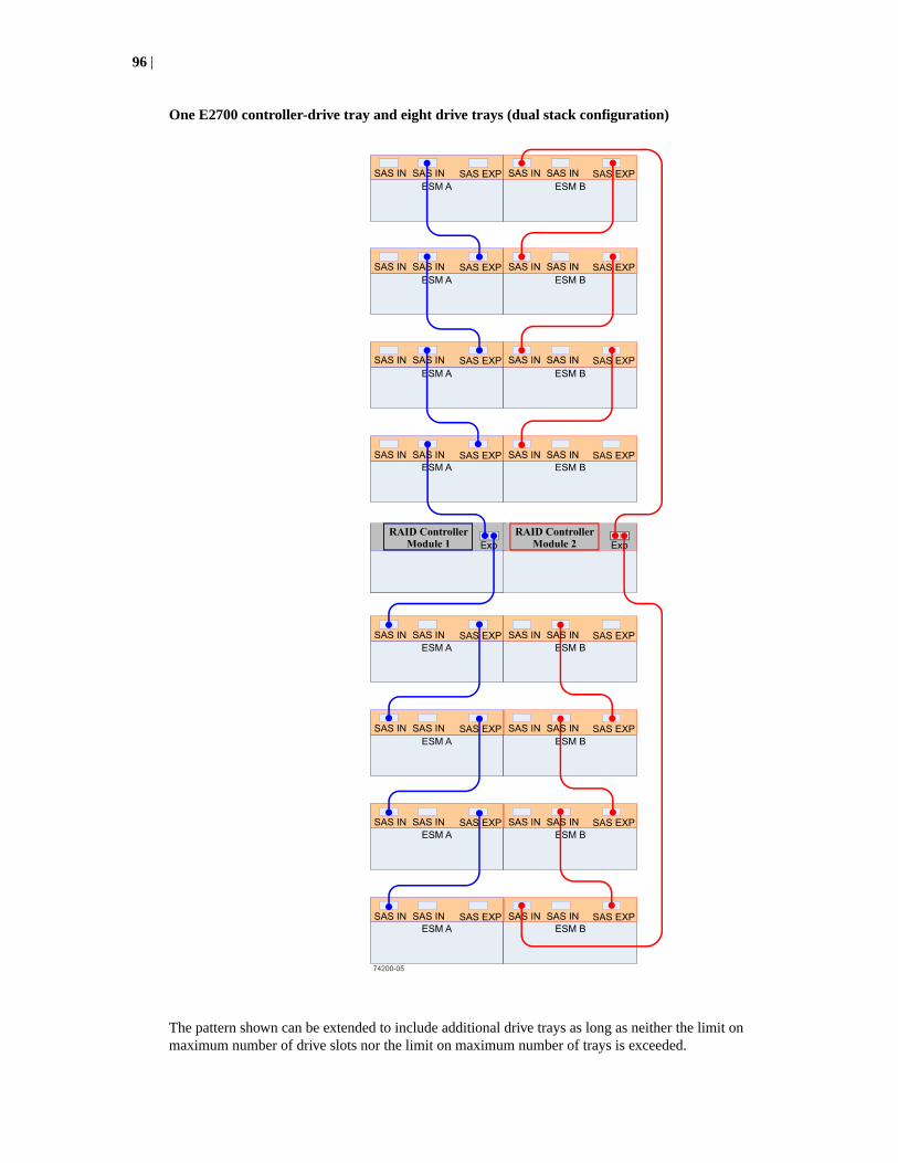
One E2700 controller-drive tray and eight drive trays (dual stack configuration)
The pattern shown can be extended to include additional drive trays as long as neither the limit onmaximum number of drive slots nor the limit on maximum number of trays is exceeded.
96 |

Drive tray cabling topologies for the E2760 controller-drive tray
This section provides examples of drive tray cabling topologies for the E2760 controller-drive tray.The E2760 controller-drive tray can be cabled only to DE6600 drive trays. The total number of drivesin the storage array, including the drives in the controller-drive tray and those in the drive trays, mustnot exceed 192.
Depending on the number of drive trays that you need to connect, see the applicable figure for acabling topology. Each example shows a duplex controller-drive tray configuration with redundantpaths to the drive trays.
Caution: Risk of bodily injury – An empty tray weighs approximately 56.7 kg (125 lb). Threepersons are required to safely move an empty tray. If the tray is populated with components, amechanized lift is required to safely move the tray.
Note: Install trays beginning from the bottom of the cabinet so that the cabinet does not becometop-heavy. A top-heavy cabinet has a greater risk of falling over.
The following figures show the SAS ports on a DE6600 drive tray. You can connect any of the SASports to the SAS Expansion port on another drive tray or on a controller-drive tray.
SAS ports on a DE6600 drive tray
1. ESM A
2. ESM B
3. SAS in port
4. SAS in port
5. SAS expansion ports
Drive shelf or drive tray cabling | 97

One E2760 controller-drive tray and one drive tray
98 |

One E2760 controller-drive tray and two drive trays (dual stack)
Using SANtricity Storage Manager to add a drive tray to anexisting storage array
If you manage your storage array with SANtricity Storage Manager, use the tasks in this section toadd a new drive tray to your storage array. If you manage your storage array with SANtricity SystemManager, use the tasks in Using SANtricity System Manager to add a drive shelf (drive tray) to anexisting storage array on page 103 to add a new drive tray to your storage array.
You can add a new drive shelf (drive tray) while power is still applied to the other components of thestorage array. You can configure, reconfigure, add, or relocate storage array capacity withoutinterrupting user access to data. System integrity is maintained throughout the process of adding andreconfiguring your storage array.
Drive shelf or drive tray cabling | 99

Note: If the drive shelf you are adding to the storage array has been previously installed in adifferent storage array, contact technical support for assistance and instructions on reinitializing thedisks in the drive shelf for use in the new storage array.
Preparing to add a drive tray
Steps for preparing to add a new drive shelf (drive tray) while power is still applied to the othercomponents of a storage array.
Before you begin
Make sure that the power source for your storage array can accommodate the power requirements ofthe new drive shelf (drive tray). Refer to the power specification for your drive shelf in the StorageSystems Site Preparation Guide. Make sure that the cabling pattern for the existing storage arraymatches one of the applicable schemes shown in this guide.
Steps
1. Select Monitor > Health > View Health (Recovery Guru) from the Array ManagementWindow (AMW).
2. Select Monitor > Health > Collect Support Data from the AMW, complete the dialog box, andselect Start.
Support data is saved to the file that you specify in the dialog box. The data is not automaticallysent to technical support.
3. From the AMW navigation bar, select Monitor > Reports > EventLog .
4. In the Event Log window, select View Only Critical Events.
5. Review the system critical events for events that have occurred in the last two to three weeks, andverify that any recent critical events have been resolved or otherwise addressed.
Note: If unresolved critical events have occurred within the previous two to three weeks, stopthe shelf hot-add procedure and contact technical support. Continue this procedure only whenthe issue is resolved.
6. Select the Hardware tab in the AMW.
7. For each drive tray in the storage array, select the View Tray Components link.
8. Select ESM Canisters from the Overall Component Information pane.
9. Confirm that the number of ESMs/IOMs detected matches the number of ESMs/IOMs installed inthe system and that for each drive shelf, both of the ESMs/IOMs show that communication is OK.
Installing the drive tray and applying power
Steps for adding a new drive shelf (drive tray) while power is still applied to the other components ofa storage array.
Steps
1. Determine which of the following options applies, and then perform the described action.
100 |

Option Description
To install a drive tray that haspreviously been installed in astorage array. (If theinstallation history of thedrive tray that you areinstalling is unknown, youshould assume that it hasbeen previously installed in astorage array.)
Remove the drives before you continue with step 2 on page 101. Thedrives must be installed one at a time later in this procedure.
To install a new drive tray anddrives that have neverpreviously been installed in astorage array.
Continue with step 2 on page 101.
2. Install the new drive tray in the rack that holds the storage array components.
Attention: See the installation instructions for your model for the full procedure for physicalinstallation and power cabling. The installation instructions for your model includes notes andwarnings that you must take into account to safely install a drive tray.
3. Power on the new drive tray and confirm that no amber warning LEDs are illuminated on thedrive tray. Resolve any fault conditions indicated by the LEDs before you continue with thisprocedure.
Connecting the drive tray
Perform these steps to connect a new drive shelf (drive tray) while power is still applied to the othercomponents of a storage array.
About this task
You may add a new drive tray while power is still applied to the other components of the storagearray so that access to data is not interrupted. Refer to the examples of drive cabling topology earlierin this chapter that apply to the hardware of your storage array. If your storage array did notpreviously have a drive tray, you will cable the new drive tray as shown for the examples of a storagearray with one drive tray. If your storage array already has one or more drive trays, this proceduredescribes how to change the cabling of the drive tray that was previously the last in a stack to connectto the new drive tray as the last in that stack. (You can add the new drive tray before the first drivetray in an existing stack. In that case you must modify this procedure accordingly.)
If you have an E2800 or E5700 storage array and manage your storage array with SANtricity SystemManager, use the tasks in Using SANtricity System Manager to add a drive shelf (drive tray) to anexisting storage array on page 103 to add a new drive tray to your storage array
Note: If you are adding the new drive tray to a storage array using a dual-stack cabling, theresulting configuration should have an equal number of drive trays in each stack, or, at most, onemore drive tray in one stack than the other.
Note: If you are adding the new drive tray to a storage array with one controller (simplexconfiguration), modify the steps in this procedure as necessary to cable only the controller A drivechannel. Multiple connections between a controller and an environmental services module (ESM)are not supported in a simplex configuration.
Note: If you are adding a DE6600 drive tray to the storage array, the drives in the front four baysin each of the five drawers must be installed before you begin this procedure. The drives in theremaining open drive bays are installed later in this procedure.
Connect the cables in the order given in the following steps.
Drive shelf or drive tray cabling | 101

Steps
1. Choose one of the following options:
Option Description
The new drive tray is the onlydrive tray in a storage arraywith an E2700 controller-drive tray.
Attach a cable between one of the SAS expansion ports on controller Aof the controller-drive tray and a SAS IN port on ISM/ESM A of the newdrive shelf (or drive tray).
The new drive tray is the onlydrive tray in a storage arraywith an E5600 controller-drive tray or an EF560 flasharray.
Attach a cable between the SAS expansion port labeled Ch 1 oncontroller A of the controller-drive tray and a SAS IN port on IOM/ESMA of the new drive shelf (or drive tray) and then attach a cable betweenthe SAS expansion port labeled Ch 1 on controller B of the controller-drive tray and the other SAS IN port on IOM/ESM A.
2. Navigate to the AMW Hardware tab, scroll down to view the new drive tray, and select ViewTray Components. If the new drive tray is not displayed in the drive tray tab, resolve theconnection issue.
Note: The AMW Recovery Guru displays a loss of redundancy error. At this point in theprocedure, you have only one active path to the controller-drive tray.
3. After the new drive tray is connected, monitor the AMW throughout the rest of this procedure tomake sure that the new drive tray does not overheat.
Note: With the bezel removed and the disk bays empty, the chassis does not achieve efficientair flow. As a result, the installation process must proceed to completion without significantdelays.
4. From the Component Information window, expand Overall Component Information, selectESM Canisters, and verify the following:
• Both ESM A and ESM B are listed.
• Current data ratefor ESM A is 12Gb/s (for E2800 controllers with DE212C or DE224C driveshelves) or 6Gb/s.
• Card communications is OK.
5. Choose one of the following options:
Option Description
The new drive tray is the onlydrive tray in a storage arraywith an E2700 controller-drive tray.
Attach a cable between one of the SAS expansion ports on controller Bof the controller-drive tray and the SAS IN port on IOM/ESM B of thenew drive shelf (or drive tray). Skip to Step 6 on page 102.
The new drive tray is the onlydrive tray in a storage arraywith an E5600 controller-drive tray or an EF560 flasharray.
Attach a cable between the SAS expansion port labeled Ch 2 oncontroller A of the controller-drive tray and a SAS IN port on ESM B ofthe new drive tray and then attach a cable between the SAS expansionport labeled Ch 2 on controller B of the controller-drive tray and theother SAS IN port on ESM B. Skip to Step 6 on page 102.
6. Navigate to the AMW Hardware tab, scroll down to view the new drive tray, and select the ViewTray Components link.
7. From the Component Information window, expand Overall Component Information, selectESM Canisters, and verify that Card communications is OK.
8. From the AMW navigation bar of the target storage array, select Monitor > Health > ViewHealth (Recovery Guru), and verify that the Recovery Guru returns no faults. Resolve any faultsindicated in the Recovery Guru before you proceed.
102 |

9. From the AMW Hardware tab, scroll down to view the newly added drive tray.
10. For drives that were previously installed in a different storage array, add one drive to the newlyinstalled drive tray and allow that drive to be recognized and displayed in the Tray Componentspane before inserting the next drive.
Note: When you install drives in the DE6600 or DE460C drive tray, the drives in the front fourbays in each of the five drawers must be installed before the drives in the remaining open drivebays are installed. Start installing drives by opening drawer one, but leave drawers two throughfive in the closed position. After the front four drives (bays one, four, seven, and ten) areinstalled in drawer one, close drawer one and open drawer two. Repeat this pattern until thefront four drive bays are filled in each of the five drawers. Open drawer one again, fill the drivebays, and securely latch the drawer. Repeat this activity for the remaining drawers until all ofthe available drive bays have been filled.
11. Repeat the previous step until all of the drives are installed.
12. In the Array Management Window, select Upgrade > View Firmware Inventory, and checkwhich versions of the ESM firmware and the drive firmware are installed on the new drive tray. Ifnecessary, upgrade the firmware to the most current version.
See the E2800 and E5700 SANtricity Software and Firmware Upgrade Guide for the upgradeprocedures.
Using SANtricity System Manager to add a drive shelf (drivetray) to an existing storage array
If you manage your storage array with SANtricity System Manager, use the tasks in this section toadd a new drive shelf to your storage array. If you manage your storage array with SANtricityStorage Manager, use the tasks in Using SANtricity Storage Manager to add a drive tray to anexisting storage array on page 99 to add a new drive tray to your storage array.
You can add a new drive shelf (drive tray) while power is still applied to the other components of thestorage array. You can configure, reconfigure, add, or relocate storage array capacity withoutinterrupting user access to data. System integrity is maintained throughout the process of adding andreconfiguring your storage array.
Note: If the drive shelf you are adding to the storage array has been previously installed in adifferent storage array, contact technical support for assistance and instructions on eitherreinitializing the disks in the drive shelf or preserving the data in the drive shelf for use in the newstorage array.
Preparing to add a drive shelf or drive tray
Perform the following steps to prepare to add a new drive shelf (drive tray) using SANtricity SystemManager while power is still applied to the other components of a storage array.
Before you begin
• The power source for your storage array must be able to accommodate the power requirements ofthe new drive shelf (drive tray). Refer to the power specification for your drive shelf in theStorage Systems Site Preparation Guide document.
• The cabling pattern for the existing storage array must match one of the applicable schemesshown in this guide.
Drive shelf or drive tray cabling | 103

Steps
1. From the Home page of SANtricity System Manager, select Support > Support Center >Diagnostics.
2. Select Collect Support Data.
The Collect Support Data dialog box appears.
3. Click Collect.
The file is saved in the Downloads folder for your browser with the name support-data.7z.The data is not automatically sent to technical support.
4. Select Support > Event Log.
The Event Log dialog box appears.
5. Select the heading of the Priority column to sort critical events to the top of the list.
6. Review the system critical events for events that have occurred in the last two to three weeks, andverify that any recent critical events have been resolved or otherwise addressed.
Note: If unresolved critical events have occurred within the previous two to three weeks, stopthe procedure and contact technical support. Continue the procedure only when the issue isresolved.
7. Select Hardware.
8. Select the IOMs (ESMs) icon.
The Shelf Component Settings dialog box appears with the IOMs (ESMs) tab selected.
9. Make sure that the status shown for each IOM/ESM is Optimal.
10. Click Show more settings.
11. Confirm that the number of ESMs/IOMs detected matches the number of ESMs/IOMs installed inthe system and that for each drive shelf, both of the ESMs/IOMs show that communication is OKand that the data rate is 12Gb/s for DE212C, DE224C, and DE460C drive shelves or 6 Gb/s forother drive trays.
Installing the drive shelf or drive tray and applying power
Perform these steps to add a new drive shelf (drive tray) using SANtricity System Manager whilepower is still applied to the other components of a storage array.
Steps
1. Choose one of the following options:
• If you are installing a drive shelf that has previously been installed in a storage array, removethe drives before you continue with Step 2 on page 101. The drives must be installed one at atime later in this procedure. If the installation history of the drive tray that you are installing isunknown, you should assume that it has been previously installed in a storage array.
• If you are installing a new drive shelf and drives that have never previously been installed in astorage array, continue with Step 2 on page 101.
2. Install the drive shelf in the rack that holds the storage array components.
Attention: See the installation instructions for your model for the full procedure for physicalinstallation and power cabling. The installation instructions for your model includes notes andwarnings that you must take into account to safely install a drive shelf/tray.
104 |

3. Power on the new drive shelf/tray, and confirm that no amber attention LEDs are illuminated onthe drive shelf. If possible, resolve any fault conditions before you continue with this procedure.
Connecting the drive shelf (drive tray)
Perform the following steps to connect a newly added drive shelf (drive tray) using SANtricitySystem Manager while power is still applied to the other components of a storage array.
About this task
Note: The following procedure applies to both drive shelves and drive trays.
You can add a new drive shelf while power is still applied to the other components of the storagearray so that access to data is not interrupted. Refer to the examples of drive cabling topology earlierin this chapter that apply to the hardware of your storage array. If your storage array did notpreviously have a drive shelf, you will cable the new drive shelf as shown for the examples of astorage array with one drive shelf. If your storage array already has one or more drive shelves, thisprocedure describes how to change the cabling of the drive shelf that was previously the last in thestack to connect to the new drive shelf as the last in the stack. (You can add the new drive shelfbetween the first drive shelf in an existing stack and the controller shelf. In that case you must modifythis procedure accordingly.)
Note: If your storage array has a mix of SAS-3 drive shelves and SAS-2 drive trays, you shoulduse a two-stack configuration with all of the SAS-3 shelves in one stack and all of the SAS-2 drivetrays in the other. Be sure to add the new drive shelf or drive tray to the appropriate stack.
Note: If you are adding the new drive shelf to a storage array with one controller (simplexconfiguration), modify the steps in this procedure as necessary to cable only one controller A drivechannel. Connections between one controller and two IOMs/ESMs are not supported in a simplexconfiguration.
Connect the cables in the order given in the following steps.
Steps
1. Choose one of the following options:
• If the new drive shelf or drive tray is the only drive shelf in the storage array, attach a cablebetween one of the SAS expansion ports on controller A of the controller shelf and a SASexpansion port 1 on IOM/ESM A of the new drive shelf.
• If the storage array already has one or more drive shelves or drive trays in a single-stackconfiguration and the new drive shelf or drive tray has the same type of SAS interface (SAS-2or SAS-3) as the existing shelves or trays, connect a cable between the SAS expansion port onIOM/ESM A of the drive shelf or drive tray that was previously the last in the stack and SASexpansion port 1 on IOM/ESM A of the new drive shelf or drive tray.
• If the storage array already has two or more drive shelves or drive trays in a dual-stackconfiguration, connect the new drive shelf or drive tray to the stack of trays or shelves whoseSAS interface (SAS-2 or SAS-3) matches that of the new drive tray or drive shelf. Connect acable between the SAS expansion port on IOM/ESM A of the drive shelf or drive tray that waspreviously the last in the stack and SAS expansion port 1 on IOM/ESM A of the new driveshelf or drive tray.
• If the storage array already has one or more drive shelves or drive trays in a single-stackconfiguration and the new drive shelf or drive tray has a different type of SAS interface(SAS-2 or SAS-3) than the existing shelves or trays, you must re-cable the storage array to adual-stack configuration. Locate the cable between SAS expansion port 2 on controller A andIOM/ESM A in the first drive tray or drive shelf in the existing stack. Disconnect that cablefrom IOM/ESM A of the tray or shelf in the existing stack and then reconnect it to IOM/ESM
Drive shelf or drive tray cabling | 105

A on the new drive shelf or drive tray. Locate the cable between SAS expansion port 2 oncontroller B and IOM/ESM B in the last drive tray or drive shelf in the existing stack.Disconnect that cable from IOM/ESM B of the tray or shelf in the existing stack and thenreconnect it to IOM/ESM B on the new drive shelf or drive tray.
2. In SANtricity System Manager, click Hardware.
Note: At this point in the procedure, you have only one active path to the controller shelf.
3. Scroll down, as necessary, to see all the of the drive shelves in the new storage array. If the newdrive shelf is not displayed, resolve the connection issue.
4. Select the ESMs/IOMs icon for the new drive tray.
The Shelf Component Settings dialog box appears.
5. If it is not already selected, select the ESMs/IOMs tab in the Shelf Component Settings dialogbox.
6. Select Show more options. Verify the following:
• IOM/ESM A is listed.
• Current data rate is 12Gb/s for a SAS-3 drive shelf or 6Gb/s for a SAS-2 drive shelf.
• Card communications is OK.
7. Choose one of the following options:
• If the new drive shelf is the only drive shelf in the storage array, attach a cable between one(or both) of the SAS expansion ports on controller B of the controller shelf and the SASexpansion port 1 (or port 1 and port 2) on IOM/ESM B of the new drive shelf.
• If the storage array already has one or more drive shelves or drive trays in a single-stackconfiguration and the new drive shelf or drive tray has the same type of SAS interface (SAS-2or SAS-3) as the existing shelves or trays, identify the cable (or cables) that run fromcontroller B to the drive shelf that was previously the last drive shelf in the stack. Disconnectthat cable (or those cables) from te SAS expansion port (or ports) of IOM/ESM B on theoriginal drive shelf and re-connect them to the SAS expansion port (or ports) on IOM/ESM Bof the new drive shelf. Connect SAS expansion port 1 on IOM/ESM B of the new drive shelfto the SAS expansion port 1 on the drive shelf that was previously the last in the stack.
• If the storage array already has one or more drive shelves or drive trays in a single-stackconfiguration and the new drive shelf or drive tray has a different type of SAS interface(SAS-2 or SAS-3) than the existing shelves or trays, you have already fully connected the newdrive tray or drive shelf in step 1.
8. If it is not already selected, select the IOMs (ESMs) tab in the Shelf Component Settingsdialog, and then select Show more settings. Verify that Card communications is YES.
Note: Optimal status indicates that the loss of redundancy error associated with the new driveshelf of drive tray has been resolved and the storage system is stabilized.
9. In the SANtricity System Manager, click Home.
10. Click the link labeled Recover from problems at the center top of the window. Resolve anyfaults indicated in the Recovery Guru before you proceed.
11. In the SANtricity System Manager, click Hardware, and scroll down, as necessary, to see thenewly added drive shelf.
12. For drives that were previously installed in a different storage array, add one drive at time to thenewly installed drive shelf. Wait for each drive to be recognized before you insert the next drive.
106 |

When a drive is recognized by the storage array, the representation of the drive slot in Hardwarewindow shows a blue rectangle.
13. Select Support > Support Center > Support Resources tab.
14. Click the Software and Firmware Inventory link, and check which versions of the IOM/ESMfirmware and the drive firmware are installed on the new drive shelf.
Note: You might need to scroll down the page to locate this link.
15. If necessary, upgrade the drive firmware.
IOM/ESM firmware automatically upgrades to the latest version unless you have disabled theupgrade feature.
Drive shelf or drive tray cabling | 107

Cabling for out-of-band management
This chapter provides examples of how to connect your storage array to an Ethernet network for out-of-band storage array management. If you plan to use in-band storage array management, Ethernetcabling might not be necessary for management connections.
For illustrations showing the Ethernet port locations on the specific controller-drive tray model thatyou are installing, see the topics under Component locations on page 22.
Attention: Possible loss of data access – If you use out-of-band management, connect theEthernet ports on the controller-drive tray to a private network segment behind a firewall. If theEthernet connection is not protected by a firewall, your storage array might be at risk of beingaccessed from outside of your network.
Direct out-of-band Ethernet topologyThe following figure shows storage array management connections from a controller shelf orcontroller-drive tray to an Ethernet network.
The following figure shows an example of direct out-of-band Ethernet topology.
74167
Controller A
EthernetPort
Controller B
EthernetPort
EthernetPort
EthernetPort
Storage ManagementStation
NetworkInterface
Card
NetworkInterface
Card
108

Fabric out-of-band Ethernet topologyThe following figure shows two storage array management connections from the controller-drive trayto two ports on an Ethernet switch. In this topology, the storage management station where the clientsoftware resides requires a NIC or some other Ethernet interface. You must use Ethernet cables for allstorage array management connections.
The following figure shows and example of fabric out-of-band topology.
74110
Ethe
rnet
Storage ManagementStation
NetworkInterface
Card
Controller A
EthernetPort
Controller B
EthernetPort
EthernetPort
EthernetPort
Note: Connect management port 1 on each controller for out-of-band management and leave port2 available for access to the storage array by technical support.
Cabling for out-of-band management | 109

Hardware installation for Synchronous Mirroringand Asynchronous Mirroring
The Asynchronous Mirroring feature uses a remote point-in-time replication method. AsynchronousMirroring differs from Synchronous Mirroring in one essential way: it captures the state of the sourcevolume at a particular point in time and includes just the data that has changed since the last imagecapture. With Asynchronous Mirroring, the remote storage array is not fully synchronized with thelocal storage array, so if the operation needs to transition to the remote storage array due to a loss ofthe local storage array, some transactions could be lost.
The Synchronous Mirroring feature is also used for online, real-time data replication between storagearrays over a remote distance. The storage array controllers manage the mirror operation. You createone or more mirrored pairs consisting of a primary volume at the local site and a secondary volume ata secondary, remote site. However, instead of batching the synchronization process using point-in-time snapshot images like in Asynchronous Mirroring, the primary volume copies all of the data fromthe primary volume to the secondary volume in a single operation. This full synchronization processtakes longer to complete, but creates a complete copy of the mirrored data. While this process is idealfor certain operations, make sure you fully understand both data mirror options before selecting oneover the other.
See to the online help system for more information about the Synchronous Mirroring feature and theAsynchronous Mirroring feature, and for software-related procedures to set the configuration of thesefeatures and use them.
Planning and site preparationThe Asynchronous Mirroring feature can be used with either Fibre Channel or iSCSI connections.Mirroring requires a duplex controller configuration. The Synchronous Mirroring feature can be usedonly with Fibre Channel connections. For Fibre Channel connections, you must have Fibre Channelswitches to create a fabric environment for data replication. For iSCSI connections, switches areoptional. The following restrictions apply to connections for Asynchronous Mirroring orSynchronous Mirroring.
• SAS and InfiniBand connections are not supported.
• iSCSI connections must use a host-connect port and not the management Ethernet port.
With the Asynchronous Mirroring feature, the following considerations apply for combining FibreChannel and iSCSI connections:
• If two storage arrays are connected through both Fibre Channel and iSCSI connections, only oneconnection type is used for a given asynchronous mirror group. However, if there are multipleasynchronous mirror groups, some asynchronous mirror groups can use Fibre Channelconnections while others use iSCSI connections.
• Failover from a Fibre Channel connection to an iSCSI connection (or vice versa) is not supported.
Switches require only minimal additional site preparation beyond basic storage array operation. Foradditional site preparation considerations for switches, including power requirements and physicaldimensions, refer to the documentation that is provided by the switch manufacturer.
iSCSI connections for Asynchronous MirroringYou can use iSCSI connections for the Asynchronous Mirroring feature. Connect one iSCSI port oneach controller of the local (primary) storage array to the corresponding controller on the remote
110

(secondary) storage array. You can make connections through a switched fabric or directly betweencontrollers. During asynchronous mirror group creation, the source storage array attempts to connectto the target storage array. The source storage array scans the IPv4 iSCSI ports in order until it finds aconnection. If the source storage array fails to find an IPv4 connection, it repeats the process usingIPv6.
Note: To improve performance, connect the lowest numbered iSCSI port on each controller of thelocal storage array to the corresponding controller on the remote storage array. This reduces delayin asynchronous mirror group creation.
Note: Make sure that Internet Control Message Protocol (ICMP) response is enabled on storagearrays used with the Asynchronous Mirroring feature. See the SANtricity online help topic "SetStorage Array ICMP Response."
Fibre Channel configurations overviewBecause of possible restrictions at the host level, the supported Synchronous Mirroring andAsynchronous Mirroring configurations contain Fibre Channel switches. These Fibre Channelswitches are zoned so that a single host adapter can access only one controller per storage array.Additionally, all configurations use a separate zone for the ports that are reserved for theSynchronous Mirroring feature or the Asynchronous Mirroring feature.
Note: Do not zone the uplink port (E_port) that connects (cascades) switches within a fabric.
Switch zoning configurations are typically set up by using the switch management software that isprovided by the manufacturer of the Fibre Channel switch. This software should have been includedwith the materials that are provided when the switch was purchased.
When two or more Fibre Channel switches are cascaded together, the switch management softwarecombines the ports for all of the switches that are linked. For example, if two 16-port Fibre Channelswitches are cascaded with a physical connection using a Fibre Channel cable, the switchmanagement software shows ports 0 through 31 participating in the fabric rather than two switcheseach with ports 0 through 15. Therefore, a zone that is created containing any of these ports can existon multiple cascaded switches.
The following figure shows both cascaded and non-cascaded switches. The top-half of the figureshows a set of cascaded switches that are on the same network. Therefore, Zone 1 is the same zoneon Switch 1A as Zone 1 is on Switch 1B. In a single-mode Fibre Channel environment, the twoswitches are connected by a single port on each switch that is designated as an E_port, which is notin a zone.
The set of switches in the bottom half of the following figure is on the same network but is notcascaded. Although both sets contain a Zone 1 (shown as Zone A in Switch 2), these zones areindependent of each other.
Hardware installation for Synchronous Mirroring and Asynchronous Mirroring | 111

For more information about Fibre Channel switch zoning or setting up a zone configuration, refer tothe manufacturer’s documentation that is provided with the switch.
Because of the varying Synchronous Mirroring configurations, the switch zone settings are presentedpreceding each configuration in this appendix.
Select one of the following configuration options to connect and configure one or more storage arraysfor use with the Synchronous Mirroring feature or the Asynchronous Mirroring feature.
112 |
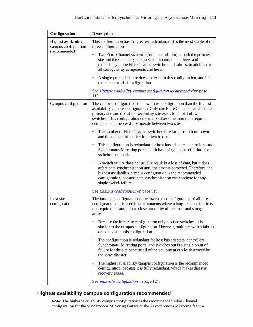
Configuration Description
Highest availabilitycampus configuration(recommended)
This configuration has the greatest redundancy. It is the most stable of thethree configurations.
• Two Fibre Channel switches (for a total of four) at both the primarysite and the secondary site provide for complete failover andredundancy in the Fibre Channel switches and fabrics, in addition toall storage array components and hosts.
• A single point of failure does not exist in this configuration, and it isthe recommended configuration.
See Highest availability campus configuration recommended on page113.
Campus configuration The campus configuration is a lower-cost configuration than the highestavailability campus configuration. Only one Fibre Channel switch at theprimary site and one at the secondary site exist, for a total of twoswitches. This configuration essentially allows the minimum requiredcomponents to successfully operate between two sites.
• The number of Fibre Channel switches is reduced from four to twoand the number of fabrics from two to one.
• This configuration is redundant for host bus adapters, controllers, andSynchronous Mirroring ports, but it has a single point of failure forswitches and fabric.
• A switch failure does not usually result in a loss of data, but it doesaffect data synchronization until the error is corrected. Therefore, thehighest availability campus configuration is the recommendedconfiguration, because data synchronization can continue for anysingle switch failure.
See Campus configuration on page 119.
Intra-siteconfiguration
The intra-site configuration is the lowest-cost configuration of all threeconfigurations. It is used in environments where a long-distance fabric isnot required because of the close proximity of the hosts and storagearrays.
• Because the intra-site configuration only has two switches, it issimilar to the campus configuration. However, multiple-switch fabricsdo not exist in this configuration.
• The configuration is redundant for host bus adapters, controllers,Synchronous Mirroring ports, and switches but is a single point offailure for the site because all of the equipment can be destroyed bythe same disaster.
• The highest availability campus configuration is the recommendedconfiguration, because it is fully redundant, which makes disasterrecovery easier.
See Intra-site configuration on page 124.
Highest availability campus configuration recommended
Note: The highest availability campus configuration is the recommended Fibre Channelconfiguration for the Synchronous Mirroring feature or the Asynchronous Mirroring feature.
Hardware installation for Synchronous Mirroring and Asynchronous Mirroring | 113

This configuration has two Fibre Channel switches at the primary site and two Fibre Channelswitches at the secondary site (four switches total), which provide for complete failover andredundancy. Failures could involve Fibre Channel switches, Fibre Channel cables, and any host orstorage array. Two Fibre Channel switches at each site also provide redundancy to the local site inaddition to a fully redundant remote configuration. No single point of failure exists in the hardwarecomponents.
The following figure shows the highest availability campus configuration. The controller-drive traysare shown schematically with four host ports on each of two controllers in each controller-drive tray.In this configuration, use the A4 connection and the B4 connection for remote mirroring trafficinstead of the A2 connection and the B2 connection. You can use controller ports A2, A3, B2, and B3for additional host access if needed.
1. Host Fibre Channel cable
2. Storage array Fibre Channel cable
3. Fibre Channel cable dedicated for mirroring
4. Fabric uplink cable
114 |

Switch zoning for highest availability campus configuration
The highest availability campus configuration provides a separate zone for each reserved port for theSynchronous Mirroring feature or the Asynchronous Mirroring feature.
The switches do not need to be zoned exactly as presented in this configuration. However, you mustmeet the following requirements when zoning switches for the highest availability campusconfiguration.
There are a total of four zones in this configuration.
• Zone 1 and zone 3 are on fabric 1 (switch 1A at the primary site, and switch 1B at the secondarysite).
• Zone 2 and zone 4 are on fabric 2 (switch 2A at the primary site, and switch 2B at the secondarysite).
Configure the zones on the switch so that there is one port per zone for a storage array connectionand one port per zone for each host. Switches are zoned so that a single host bus adapter port canaccess only one controller per storage array.
Switches are zoned so that a single host bus adapter port can access only one controller for eachstorage array.
Note: Do not zone the uplink ports (E_ports) on any of the Fibre Channel switches.
The following figure shows how the four switches are zoned for the highest availability campusconfiguration.
The switches have 16 ports each, which leaves unused ports on each switch when following thepreceding requirements. The remaining ports can be distributed among the other zones. It isrecommended, however, that most of the remaining ports be assigned to the zones containing the hostconnections: zone 1 and zone 2. This port assignment allows easy setup for additional hosts toconnect to the environment.
3
2
5
4
7
6
9
8
11
10 12
13 15
14
1
0Zone 2Zone 1
17
16
19
18
21
20
23
22
25
24
27
26
29
28
31
30Zone 1 Zone 2
17
16
19
18
21
20
23
22
25
24
27
26
29
28
31
30Zone 1 Zone 2
3 5 7 9 13 15
2 4 6 8
11
10 12 14
1
0Zone 2Zone 1
84004-02
Zone 3Zone 3Zone 4 Zone 4
Zone 3Zone 3Zone 4 Zone 4
Switch 2A Switch 2BFabric 210 km Maximum
Switch 1A Switch 1BFabric 110 km Maximum
Before you proceed, review the requirements listed in this section and the zoning shown in the figureto make sure that all four switches are correctly zoned. For more information, see the Fibre Channelconfigurations overview on page 111.
Hardware installation for Synchronous Mirroring and Asynchronous Mirroring | 115

Cabling for the highest availability campus configuration
After the four Fibre Channel switches are correctly zoned, set up the highest availability campusconfiguration for the Synchronous Mirroring feature or the Asynchronous Mirroring feature.
About this task
Note: Start the installation at the primary site. Repeat these steps for the secondary site wheninstructed to do so.
After the four Fibre Channel switches are correctly zoned, set up the highest availability campusconfiguration for the Synchronous Mirroring feature or the Asynchronous Mirroring feature.
Complete all connections by using Fibre Channel cables of the correct length.
Steps
1. Determine whether you adding equipment to an existing storage array environment.
• If so, stop I/O activity from all hosts before proceeding. Go to Step 2 on page 116.
• If not, the storage array installation is new. Go to Step 3 on page 116.
Attention: Possible hardware damage – DC-powered controller-drive trays have specialpower procedures that you must follow beyond the procedures for AC-powered trays. To getspecific power-off and power-on procedures, refer to the installation instructions for yourstorage array.
2. Turn off the power to all storage arrays, hosts, Fibre Channel switches, and any other equipmentin the storage array environment.
3. Make sure that cabling between all of the controller-drive trays and the drive trays is complete.
Example
Note: Depending on which site is being configured, switch 1 represents switch 1A for theprimary site and switch 1B for the secondary site. This representation applies to switch 2 aswell.
4. Connect the primary host bus adapter for each local host to an available port in zone 1 of switch1.
The following figure shows the cabling that is described in Step 4 on page 116 and Step 5 on page117.
116 |

Zo ne 4
75083
3
2
5
4
7
6
9
8
11
10 12
13 15
14
1
0Zo ne 2Zo ne 1
3
2
5
4
7
6
9
8
11
10 12
13 15
14
1
0Zo ne 2Zo ne 1
Zo ne 3Zo ne 4
Zo ne 3
S witc h 1
S witc h 2
Ho s t 1 Ho s t 2
Ho s t Gro u p
HBA1a HBA1b HBA2a HBA2b
5. Connect the secondary host bus adapter for each host at this site to an available port in zone 1 ofswitch 2.
6. Connect controller port A1 of the storage array to an available port in zone 1 of switch 1.
The figure following Step 9 on page 117 shows the cabling for E2700 controller-drive trays.
7. Connect controller port B1 of the storage array to an available port in zone 1 of switch 2.
8. Connect controller port A2 of the storage array to an available port in zone 2 of switch 1. In afour-host-port system, connect controller port A4 to an available port in zone 2 of switch 1.
9. Connect controller port B2 of the storage array to an available port in zone 2 of switch 2. In afour-host-port system, connect controller port B4 to an available port in zone 2 of switch 2.
Hardware installation for Synchronous Mirroring and Asynchronous Mirroring | 117

Note: Controller port A2 and controller port B2 are reserved for mirror relationshipsynchronization upon activation of the Synchronous Mirroring feature. In a four-host-portsystem, controller port A4 and controller port B4 are reserved.
The primary site cabling is now complete.
10. Determine whether the secondary site cabling complete.
• If not, repeat Step 1 on page 116 through Step 9 on page 117 for the secondary site.
• If so, go to Step 11 on page 118.
11. Complete the fabric environment for switch 1 by connecting switch 1A to switch 1B.
The following figure shows the cabling that is described in Step 11 on page 118 and Step 12 onpage 119.
3
2
5
4
7
6
9
8
11
10 12
13 15
14
1
0Zone 2Zone 1
17
16
19
18
21
20
23
22
25
24
27
26
29
28
31
30Zone 1 Zone 2
17
16
19
18
21
20
23
22
25
24
27
26
29
28
31
30Zone 1 Zone 2
3 5 7 9 13 15
2 4 6 8
11
10 12 14
1
0Zone 2Zone 1
84004-02
Zone 3Zone 3Zone 4 Zone 4
Zone 3Zone 3Zone 4 Zone 4
Switch 2A Switch 2BFabric 210 km Maximum
Switch 1A Switch 1BFabric 110 km Maximum
118 |

12. Repeat Step 11 on page 118 for switch 2A and switch 2B to complete the fabric environment forswitch 2.
Cabling for the highest availability campus configuration is complete.
13. Repeat Step 4 on page 116 through Step 10 on page 118 for other storage arrays that exist in thesame cabinet that use the Synchronous Mirroring feature or the Asynchronous Mirroring feature.
Attention: Possible hardware damage – DC-powered controller-drive trays have specialpower procedures that you must follow beyond the procedures for AC-powered trays. To getspecific power-off and power-on procedures, refer to the installation instructions for yourstorage array.
14. Turn on the power to all of the storage array hosts, Fibre Channel switches, and any otherhardware at both sites where the power was turned off.
Result
The hardware installation is complete. To configure the storage management software to supportmirror relationships, refer to the online help topics.
Campus configuration
The campus configuration offers the same functionality as the highest availability campusconfiguration, but the campus configuration contains only one switch at each site, rather than two.The configuration is still redundant for host bus adapters, controllers, and remote mirroring ports, butthe configuration has a single point of failure for switches. If a switch at either site fails, theSynchronous Mirroring feature or the Asynchronous Mirroring feature cannot operate. For thisreason, the highest availability campus configuration is highly recommended for total environmentredundancy.
The following figure shows a complete campus configuration. The controller-drive trays are shownschematically with four host ports on each of two controllers in each controller-drive tray.
Hardware installation for Synchronous Mirroring and Asynchronous Mirroring | 119

1. Host Fibre Channel cable
2. Storage array Fibre Channel cable
3. Fibre Channel cable dedicated for mirroring
4. Fabric uplink cable
Switch zoning for the campus configuration
The campus configuration allows for a separate zone for each reserved port for the SynchronousMirroring feature or the Asynchronous Mirroring feature.
The switches do not need to be zoned exactly as presented in this configuration. However, you mustmeet the following requirements when you zone switches for the campus configuration.
Note: Do not zone the uplink ports (E_ports) on any of the Fibre Channel switches.
You must have a total of four zones in this configuration.
• All zones exist on fabric 1 (switch 1A at the primary site, and switch 1B at the secondary site).
• Zone 3 and zone 4 are reserved for the dedicated Synchronous Mirroring feature connections.
120 |

You must configure the zones on the switches so that there is one port per zone for a storage arrayconnection and one port per zone for each host.
You must zone the switches so that a single host adapter can access only one controller per storagearray.
The switches in the following figure contain 16 ports each, which leaves many unused ports perswitch. The remaining ports can be distributed among the other zones. However, it is recommendedthat most remaining ports be assigned to the zones that contain the host connections (zone 1). Thissetup allows connections for additional hosts.
The following figure shows how the two switches are zoned for the campus configuration.
17
16
19
18
21
20
23
22
25
24
27
26
29
28
31
30Zo ne 1 Zo ne 2
3
2
5
4
7
6
9
8
11
10 12
13 15
14
1
0Zo ne 2Zo ne 1
75087 Zo ne 3Zo ne 3Zo ne 4 Zo ne 4
S witc h 1A S witc h 1BFa b ric 1
Review the requirements in this section and the zoning example in the figure above to make sure thatboth switches are correctly zoned before proceeding. For more information, see Fibre Channelconfigurations overview on page 111.
Cabling for the campus configuration
After both Fibre Channel switches are correctly zoned, set up the campus configuration for theSynchronous Mirroring feature or the Asynchronous Mirroring feature.
About this task
Start the installation at the primary site. Repeat these steps for the secondary site when instructed todo so.
Hardware installation for Synchronous Mirroring and Asynchronous Mirroring | 121

Note: Complete all connections by using Fibre Channel cables of the correct length.
Steps
1. Determine whether you adding equipment for mirroring to an existing storage array environment.
• If so, stop I/O activity from all hosts before proceeding. Go to Step 2 on page 122.
• If not, this is a new storage array installation. Go to Step 3 on page 122.
Attention: Possible hardware damage – DC-powered controller-drive trays have specialpower procedures that you must follow beyond the procedures for AC-powered trays. To getspecific power-off and power-on procedures, see the installation instructions for your storagearray.
2. Turn off the power to all storage arrays, hosts, Fibre Channel switches, and any other equipmentin the storage array environment.
3. Make sure that basic cabling between all of the controller-drive trays and the drive trays on bothstorage arrays is complete.
Note: Depending on which site is being configured, switch 1 represents switch 1A for theprimary site and switch 1B for the secondary site.
Note: You can connect the cables to any port in the correct zone of the switch.
4. Connect the primary host bus adapter for each host at this site to an available port in zone 1 ofswitch 1A.
The following figure shows the cabling that is described in Step 4 on page 122 and Step 5 on page122.
5. Connect the secondary host bus adapter for each host at this site to an available port in zone 2 ofswitch 1A.
The following figure shows connections between a host bus adapter and a Fibre Channel switch.
3
2
5
4
7
6
9
8
11
10 12
13 15
14
1
0Zo ne 2Zo ne 1
S witc h 1A
75088
Zo ne 3Zo ne 4
Ho s t 1
HBA1a HBA1b HBA2a HBA2b
Ho s t 2
Ho s t Gro u p
6. Connect controller port A1 of the storage array to an available port in zone 1 of switch 1A.
The first figure following Step 9 on page 123 shows the storage array connected to Fibre Channelswitches that is described in Step 6 on page 122 through Step 9 on page 123. The second figure
122 |

following Step 9 on page 123 shows the cabling configuration schematically with four host portson each of two controllers in each controller-drive tray.
7. Connect controller port B1 of the storage array to an available port in zone 2 of switch 1A.
8. Connect controller port A2 of the storage array to an available port in zone 3 of switch 1A. In afour-host-port system, connect controller port A4.
9. Connect controller port B2 of the storage array to an available port in zone 4 of switch 1A. In afour-host-port system, connect controller port B4.
Note: Controller ports A2 and B2 are reserved for mirror relationship synchronization uponactivation of the Synchronous Mirroring feature or the Asynchronous Mirroring feature. In afour-host-port system, controller port A4 and controller port B4 are reserved.
The following figure shows connections between a storage array and a Fibre Channel switch.
3
2
5
4
7
6
9
8
11
10 12
13 15
14
1
0Zo ne 2Zo ne 1
Zo ne 3Zo ne 4
S witch 1A84004-04
A1 A2 A3 A4
B1 B2 B3 B4
A5 A6
B5 B6
Storage Array
1.2 .
The primary site cabling is now complete.
10. Determine whether the secondary site cabling complete.
• If not, repeat Step 1 on page 122 through Step 9 on page 123 for the secondary site.
• If so, go to Step 11 on page 123.
11. Complete fabric 1 by connecting switch 1A to switch 1B.
The following figure shows the cabling that is described in this step.
The following figure shows connections between remote switches to complete the switchedfabric.
Hardware installation for Synchronous Mirroring and Asynchronous Mirroring | 123

17
16
19
18
21
20
23
22
25
24
27
26
29
28
31
30Zone 1 Zone 2
3
2
5
4
7
6
9
8
11
10 12
13 15
14
1
0Zone 2Zone 1
Switch 1A Switch 1BFabric 1
84004-06 Zone 3Zone 3Zone 4 Zone 4
Cabling for the campus configuration is complete.
12. Repeat Step 4 on page 122 through Step 10 on page 123 for any additional storage arrays thatexist in the same cabinet that will use the Synchronous Mirroring feature or the AsynchronousMirroring feature.
Attention: Possible hardware damage – DC-powered controller-drive trays have specialpower procedures that you must follow beyond the procedures for AC-powered trays. To getspecific power-off and power-on procedures, see the installation instructions for your storagearray.
13. Turn on the power to all storage arrays, hosts, Fibre Channel switches, and any other hardware atboth sites where the power was turned off.
Result
Hardware installation is complete. See the online help topics for procedures to configure the storagemanagement software to support mirror relationships.
Intra-site configuration
The intra-site configuration is used in environments where a long-distance fabric is not requiredbecause of the close proximity of the hosts and storage arrays. The configuration is still redundant forhost bus adapters, controllers, remote mirroring ports, and switches, but the configuration is a singlepoint of failure for the site because all of the equipment can be destroyed by the same disaster. Forthis reason, the highest availability campus configuration is highly recommended for totalenvironment redundancy.
The following figure shows a complete installation of the intra-site configuration.
Note: A switch failure in this configuration does not affect data access; however, as a result, anUnsynchronized state might occur for all of the mirror relationships on both the primary storagearrays and the secondary storage arrays.
124 |

1. Host Fibre Channel cable
2. Storage array Fibre Channel cable
3. Fibre Channel cable dedicated for mirroring
Switch zoning for the intra-site configuration
The intra-site configuration provides switch redundancy, but the switches are not cascaded and areindependent of each other.
Note: The switches do not need to be zoned exactly as presented in this configuration. However,you must meet the following requirements when zoning switches for the intra-site configuration.
You must have a total of four zones on each controller in this configuration.
You must configure the zones on the switch so that there is one port per zone for a storage arrayconnection and one port per zone for each host.
You must zone the switches so that a single host adapter can only access one controller per storagearray.
The switches in the following figure contain 16 ports each, which leaves many unused ports perswitch. The remaining ports can be distributed among the other zones. However, make sure that mostof the remaining ports are assigned to the zones that contain the host connections: zone 1 and zone 2.This assignment allows for easy setup for connecting additional hosts.
For simplicity, in this example, the switches use one-half of the ports for each zone, although zone 3and zone 4 require fewer ports.
Hardware installation for Synchronous Mirroring and Asynchronous Mirroring | 125

Before proceeding, review the requirements in this section and the zoning example in the figures tomake sure that both switches are correctly zoned. For more information, see Fibre ChannelConfigurations Overview on page 111.
Cabling for the intra-site configuration
After both Fibre Channel switches are correctly zoned, set up the intra-site configuration for theSynchronous Mirroring feature or the Asynchronous Mirroring feature.
About this task
Note: Complete all connections by using Fibre Channel cables of the correct length.
Steps
1. Determine whether you are adding equipment for the Synchronous Mirroring feature or theAsynchronous Mirroring feature to an existing storage array environment.
• If so, stop I/O activity from all hosts before proceeding. Go to Step 2 on page 126.
• If not, this is a new storage array installation. Go to Step 3 on page 126.
Attention: Possible hardware damage – DC-powered controller-drive trays and drive trayshave special power procedures that you must follow beyond the procedures for AC-poweredtrays. To get specific power-off and power-on procedures, see the installation guide for yourstorage array.
2. Turn off the power to all storage arrays, hosts, Fibre Channel switches, and any other equipmentin the storage array environment.
3. Make sure that basic cabling between all of the controller trays or controller-drive trays and thedrive trays is complete on both storage arrays as described in this document.
4. Connect the primary host bus adapter for each host to an available port in zone 1 of switch 1.
The following figure shows the cabling that is described in Step 4 on page 126.
Note: You can connect the cables to any port in the correct zone of the switch.
126 |

5. Connect the secondary host bus adapter for each host to an available port in zone 1 of switch 2.
The following figure shows the cabling that is described in this step.
6. Connect controller port A1 of the primary storage array to an available port in zone 1 of switch 1.
Hardware installation for Synchronous Mirroring and Asynchronous Mirroring | 127

The following figure shows the cabling that is described in Step 6 on page 127 through Step 9 onpage 128.
1. Host Fibre Channel cable
2. Storage array Fibre Channel cable
3. Fibre Channel cable dedicated for mirroring
7. Connect controller port B1 of the primary storage array to an available port in zone 3 of switch 2.
8. Connect controller port A2 of the primary storage array to an available port in zone 2 of switch 1.In a four-host-port system, connect controller port A4 to an available port in zone 2 of switch 1.
9. Connect controller port B2 of the primary storage array to an available port in zone 4 of switch 2.In a four-host-port system, connect controller port B4 to an available port in zone 4 of switch 2.
Note: Upon activation of the Synchronous Mirroring feature or the Asynchronous Mirroringfeature, controller port A2 and controller port B2 are reserved for mirror relationshipsynchronization. In a four-host-port system, controller port A4 and controller port B4 arereserved.
10. Connect controller port A1 of the secondary storage array to an available port in zone 1 of switch1.
The figure following Step 13 on page 128 shows the cabling described in Step 6 on page 127through Step 9 on page 128.
11. Connect controller port B1 of the secondary storage array to an available port in zone 3 of switch2.
12. Connect controller port A2 of the secondary storage array to an available port in zone 2 of switch1. In a four-host-port system, connect controller port A4 to an available port in zone 2 of switch 1.
13. Connect controller port B2 of the secondary storage array to an available port in zone 4 of switch2. In a four-host-port system, connect controller port B4 to an available port in zone 4 of switch 2.
128 |

1. Host Fibre Channel cable
2. Storage array Fibre Channel cable
3. Fibre Channel cable dedicated for mirroring
Cabling for the intra-site configuration is complete.
14. Repeat Step 4 on page 126 through Step 13 on page 128 for any additional storage arrays thatexist in the same cabinet that will use the Synchronous Mirroring feature or the AsynchronousMirroring feature.
Attention: Possible hardware damage – DC-powered controller-drive trays and drive trayshave special power procedures that you must follow beyond the procedures for AC-poweredtrays. To get specific power-off and power-on procedures, see the installation guide for yourstorage array.
15. Turn on the power to all storage arrays, hosts, Fibre Channel switches, and any other hardwarewhere power was turned off.
Result
The hardware installation is complete. See the online help topics for procedures to configure thestorage management software to support mirror relationships.
Installing and using mirroring with a wide area network
When installing and using the Synchronous Mirroring feature or the Asynchronous Mirroring featureover a wide area network (WAN), keep these guidelines in mind:
• If you are setting up an FCIP router to perform mirroring, go to the Compatibility Matrix. SelectRouter-FCIP in the Product field, and select the release of the storage management softwarethat you use in the Software Release field. Verify that the maximum latency and distance aresupported by referring to the vendor specifications for your router and by checking the NetAppInteroperability Matrix Tool (IMT) site at http://mysupport.netapp.com/matrix.
• FCIP router vendors and telecommunication vendors are responsible for setting up routing.
Hardware installation for Synchronous Mirroring and Asynchronous Mirroring | 129

• The smaller the bandwidth on the WAN, the longer it takes a mirror to synchronize.
• If the bandwidth does not exceed the average rate, you might not be able to synchronize the dataat all. For example, if the system writes at 1 Mb/s, it needs 2 Mb/s of bandwidth available.
• If the mirroring is lagging far behind during production hours, suspend the mirror. During off-peak hours, resume the mirror.
• If you need to keep the Synchronous Mirroring on at all times, keep the mirror physically as closeas possible to the production site.
• To determine the average write rate, you should use the available system utilities and should takemeasurements during peak times.
• If you anticipate adding any applications, determine the bandwidth needs for any futureapplications.
• Acceptable lag times vary depending on the environment and should be determined on anindividual basis.
Line capacities
Line type Capacity in Mb/s Speed in MB/s
T-1 1.544 0.193
T-3 43.232 5.404
OC-3 155.6352 19.454
OC-12 622.5408 77.8176
OC-48 2490.1632 311.27
OC-192 9960.6528 1245.085
The following table shows average write operations in Mb/s with corresponding line capacitycalculations. When the line capacity calculation is below 50 percent, the result is an adequateresponse-time performance and a limited need for delta logging (when the mirror lags behind thedata). When the line capacity calculation is above 50 percent, the mirror can never catch up. Anytransfers above 50 percent will start to lag.
Average write timein Mb/s
T-1 T-3 OC-3 OC-12 OC-18 OC-192
0.01 5.2% 0.2% 0.1% 0.0% 0.0% 0.0%
0.1 51.8% 1.9% 0.5% 0.1% 0.0% 0.0%
1 518.1% 18.5% 5.1% 1.3% 0.3% 0.1%
10 5181.3% 185.3% 51.4% 12.9% 3.2% 0.8%
130 |

Copyright information
Copyright © 2018 NetApp, Inc. All rights reserved. Printed in the U.S.
No part of this document covered by copyright may be reproduced in any form or by any means—graphic, electronic, or mechanical, including photocopying, recording, taping, or storage in anelectronic retrieval system—without prior written permission of the copyright owner.
Software derived from copyrighted NetApp material is subject to the following license anddisclaimer:
THIS SOFTWARE IS PROVIDED BY NETAPP "AS IS" AND WITHOUT ANY EXPRESS ORIMPLIED WARRANTIES, INCLUDING, BUT NOT LIMITED TO, THE IMPLIEDWARRANTIES OF MERCHANTABILITY AND FITNESS FOR A PARTICULAR PURPOSE,WHICH ARE HEREBY DISCLAIMED. IN NO EVENT SHALL NETAPP BE LIABLE FOR ANYDIRECT, INDIRECT, INCIDENTAL, SPECIAL, EXEMPLARY, OR CONSEQUENTIALDAMAGES (INCLUDING, BUT NOT LIMITED TO, PROCUREMENT OF SUBSTITUTEGOODS OR SERVICES; LOSS OF USE, DATA, OR PROFITS; OR BUSINESS INTERRUPTION)HOWEVER CAUSED AND ON ANY THEORY OF LIABILITY, WHETHER IN CONTRACT,STRICT LIABILITY, OR TORT (INCLUDING NEGLIGENCE OR OTHERWISE) ARISING INANY WAY OUT OF THE USE OF THIS SOFTWARE, EVEN IF ADVISED OF THEPOSSIBILITY OF SUCH DAMAGE.
NetApp reserves the right to change any products described herein at any time, and without notice.NetApp assumes no responsibility or liability arising from the use of products described herein,except as expressly agreed to in writing by NetApp. The use or purchase of this product does notconvey a license under any patent rights, trademark rights, or any other intellectual property rights ofNetApp.
The product described in this manual may be protected by one or more U.S. patents, foreign patents,or pending applications.
RESTRICTED RIGHTS LEGEND: Use, duplication, or disclosure by the government is subject torestrictions as set forth in subparagraph (c)(1)(ii) of the Rights in Technical Data and ComputerSoftware clause at DFARS 252.277-7103 (October 1988) and FAR 52-227-19 (June 1987).
131

Trademark information
NETAPP, the NETAPP logo, and the marks listed on the NetApp Trademarks page are trademarks ofNetApp, Inc. Other company and product names may be trademarks of their respective owners.
http://www.netapp.com/us/legal/netapptmlist.aspx
132

How to send comments about documentation andreceive update notifications
You can help us to improve the quality of our documentation by sending us your feedback. You canreceive automatic notification when production-level (GA/FCS) documentation is initially released orimportant changes are made to existing production-level documents.
If you have suggestions for improving this document, send us your comments by email.
To help us direct your comments to the correct division, include in the subject line the product name,version, and operating system.
If you want to be notified automatically when production-level documentation is released orimportant changes are made to existing production-level documents, follow Twitter account@NetAppDoc.
You can also contact us in the following ways:
• NetApp, Inc., 495 East Java Drive, Sunnyvale, CA 94089 U.S.
• Telephone: +1 (408) 822-6000
• Fax: +1 (408) 822-4501
• Support telephone: +1 (888) 463-8277
133