Embed Size (px)
Citation preview

E. Noah, CMS Tracker Week, January 2003
APV Power Dependence on Trigger: First Observations on Hybrid
• Effect first observed in Strasbourg and reported by Jean-Daniel Berst.
• Large drop in hybrid current when the trigger is removed. I250 ~ 230 mA for a 6 APV module
I250 ~ 160 mA for a 4 APV module (from 660 mA to 500 mA)
• Following the removal of triggers, the current decreases slowly and stabilises with a time constant of a few seconds.
• Normal current is sustained with trigger rates above a few Hz
E. Noah, CMS Tracker Week, January 2003
First Observations on a Hybrid
• Where does the current change occur on the hybrid?
• What is its dependence on trigger rate?
• What is its exact magnitude?
• How important will this effect be for CMS?
E. Noah, CMS Tracker Week, January 2003
Measurements on the APV25
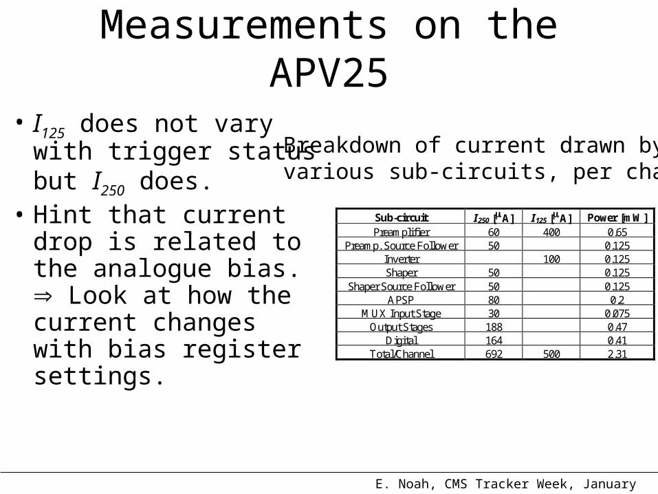
• I125 does not vary with trigger status but I250 does.
• Hint that current drop is related to the analogue bias. Look at how the current changes with bias register settings.
Breakdown of current drawn byvarious sub-circuits, per channel
Sub-circuit I250 [A] I125 [A] Power [mW] Preamplifier 60 400 0.65
Preamp. Source Follower 50 0.125 Inverter 100 0.125 Shaper 50 0.125
Shaper Source Follower 50 0.125 APSP 80 0.2
MUX Input Stage 30 0.075 Output Stages 188 0.47
Digital 164 0.41 Total/Channel 692 500 2.31
E. Noah, CMS Tracker Week, January 2003
Measurements on the APV25
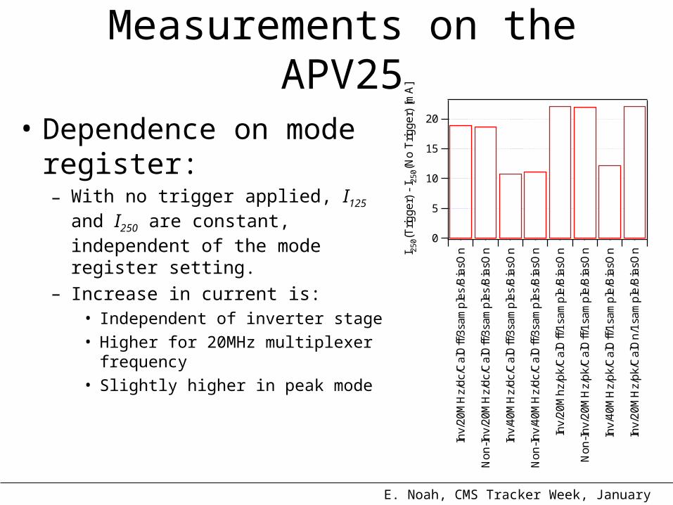
• Dependence on mode register:– With no trigger applied, I125 and I250 are
constant, independent of the mode register setting.
– Increase in current is:• Independent of inverter stage
• Higher for 20MHz multiplexer frequency
• Slightly higher in peak mode
20
15
10
5
0
I 25
0(T
rigg
er)
- I 2
50(
No
Trig
ge
r) [
mA
]
Inv/
20
MH
z/d
c/C
alO
ff/3
sam
ple
s/B
iasO
n
No
n-I
nv/
20
MH
z/d
c/C
alO
ff/3
sam
ple
s/B
iasO
n
Inv/
40
MH
z/d
c/C
alO
ff/3
sam
ple
s/B
iasO
n
No
n-I
nv/
40
MH
z/d
c/C
alO
ff/3
sam
ple
s/B
iasO
n
Inv/
20
Mh
z/p
k/C
alO
ff/1
sam
ple
/Bia
sOn
No
n-I
nv/
20
MH
z/p
k/C
alO
ff/1
sam
ple
/Bia
sOn
Inv/
40
MH
z/p
k/C
alO
ff/1
sam
ple
/Bia
sOn
Inv/
20
MH
z/p
k/C
alO
n/1
sam
ple
/Bia
sOn
E. Noah, CMS Tracker Week, January 2003
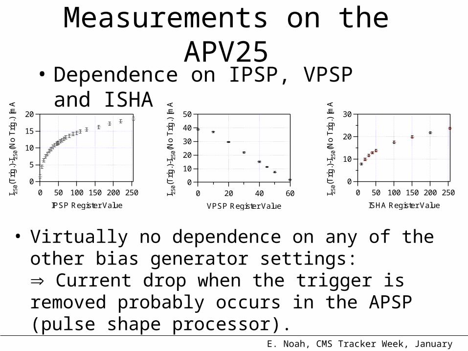
Measurements on the APV25• Dependence on IPSP, VPSP and ISHA
• Virtually no dependence on any of the other bias generator settings: Current drop when the trigger is removed probably occurs in the APSP (pulse shape processor).
20
15
10
5
0
I 25
0(T
rig.)
-I25
0(N
o T
rig.)
[m
A]
250200150100500
IPSP Register Value
50
40
30
20
10
0
I 25
0(T
rig.)
-I25
0(N
o T
rig.)
[m
A]
6040200
VPSP Register Value
30
20
10
0
I 25
0(T
rig.)
-I25
0(N
o T
rig.)
[m
A]
250200150100500
ISHA Register Value

E. Noah, CMS Tracker Week, January 2003
Measurements on a Hybrid
• 4 x APV module• Measure:
– Hybrid current with clock and trigger– Hybrid current with clock but without trigger– Hybrid current without both clock and trigger
• Check that measurements are consistent with those carried out on the stand alone APV25.
E. Noah, CMS Tracker Week, January 2003
Measurements on a Hybrid
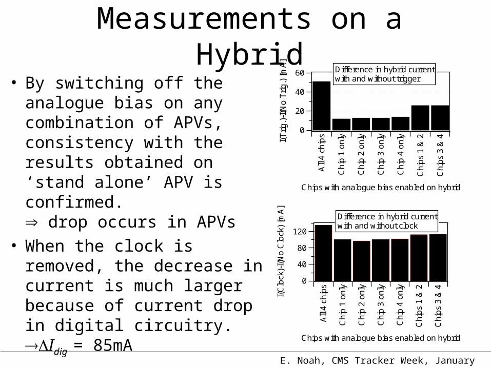
• By switching off the analogue bias on any combination of APVs, consistency with the results obtained on ‘stand alone’ APV is confirmed. drop occurs in APVs
• When the clock is removed, the decrease in current is much larger because of current drop in digital circuitry. Idig = 85mA
60
40
20
0
I(T
rig.)
-I(N
o T
rig.)
[m
A]
All
4 c
hip
s
Ch
ip 1
on
ly
Ch
ip 2
on
ly
Ch
ip 3
on
ly
Ch
ip 4
on
ly
Ch
ips
1 &
2
Ch
ips
3 &
4
Chips with analogue bias enabled on hybrid
Difference in hybrid currentwith and without trigger
120
80
40
0I(
Clo
ck)-
I(N
o C
lock
) [m
A]
All
4 c
hip
s
Ch
ip 1
on
ly
Ch
ip 2
on
ly
Ch
ip 3
on
ly
Ch
ip 4
on
ly
Ch
ips
1 &
2
Ch
ips
3 &
4
Chips with analogue bias enabled on hybrid
Difference in hybrid currentwith and without clock

E. Noah, CMS Tracker Week, January 2003
Measurements on a Hybrid• Dependence of current drop on bias register settings when the trigger is removed
150
100
50
0
I(T
rig.)
-I(N
o T
rig.)
[m
A]
6040200
VPSP Register Value
Difference in hybrid current with/without trigger vs. VPSP
250200150100
500
I(C
lock
)-I(
No
Clo
ck)
[mA
]
6040200
VPSP Register Value
Difference in hybrid currentwith/without clock vs. VPSP
80
60
40
20
0
I(T
rig.)
-I(N
o T
rig.)
[m
A]
250200150100500
IPSP Register Value
Difference in hybrid currentwith/without trigger vs. IPSP
200
150
100
50
0
I(C
lock
)-I(
No
Clo
ck)
[mA
]
250200150100500
IPSP Register Value
Difference in hybrid currentwith/without clock vs. IPSP
80
60
40
20
0
I(T
rig.)
-I(N
o T
rig.)
[m
A]
250200150100500
ISHA Register Value
Difference in hybrid currentwith/without trigger vs. ISHA
200
150
100
50
0
I(C
lock
)-I(
No
Clo
ck)
[mA
]
250200150100500
ISHA Register Value
Difference in hybrid currentwith/without clock vs. ISHA
• Dependence of current drop on bias register settings when the clock is removed
E. Noah, CMS Tracker Week, January 2003
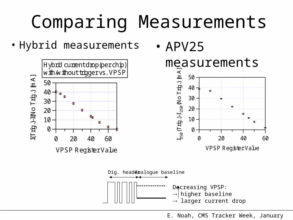
Comparing Measurements• Hybrid measurements
5040302010
0
I(T
rig.)
-I(N
o T
rig.)
[mA
]
6040200
VPSP Register Value
Hybrid current drop(per chip)with/without trigger vs. VPSP
50
40
30
20
10
0
I 250
(Trig
.)-I
250(N
o T
rig.)
[mA
]
6040200
VPSP Register Value
• APV25 measurements
Dig. header Analogue baseline
Decreasing VPSP: higher baseline larger current drop
E. Noah, CMS Tracker Week, January 2003
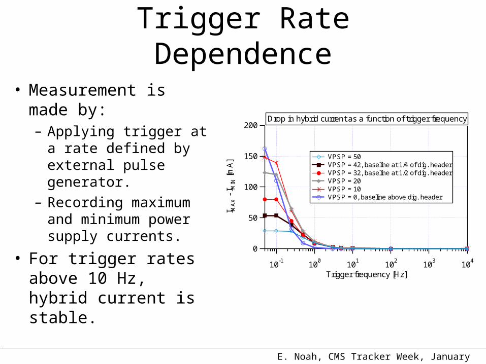
Trigger Rate Dependence
• Measurement is made by: – Applying trigger at a
rate defined by external pulse generator.
– Recording maximum and minimum power supply currents.
• For trigger rates above 10 Hz, hybrid current is stable.
200
150
100
50
0
I MA
X -
I MIN
[m
A]
10-1
100
101
102
103
104
Trigger frequency [Hz]
VPSP = 50 VPSP = 42, baseline at 1/4 of dig. header VPSP = 32, baseline at 1/2 of dig. header VPSP = 20 VPSP = 10 VPSP = 0, baseline above dig. header
Drop in hybrid current as a function of trigger frequency
E. Noah, CMS Tracker Week, January 2003
Summary• I250 drops with low trigger rates applied to hybrids:
– Trigger removal initiates a current drop which occurs with a time constant of ~ seconds.
– When trigger is applied, current rises rapidly.
• Effect originates in the APVs, probably the APSP since it is sensitive to VPSP, IPSP and ISHA.
• For a hybrid operated with default settings and APV analogue baseline ¼ of digital header, drop in current is 10%.
• Effect of removing the clock was also measured: current drop is much larger because of contribution from digital circuitry.
E. Noah, CMS Tracker Week, January 2003
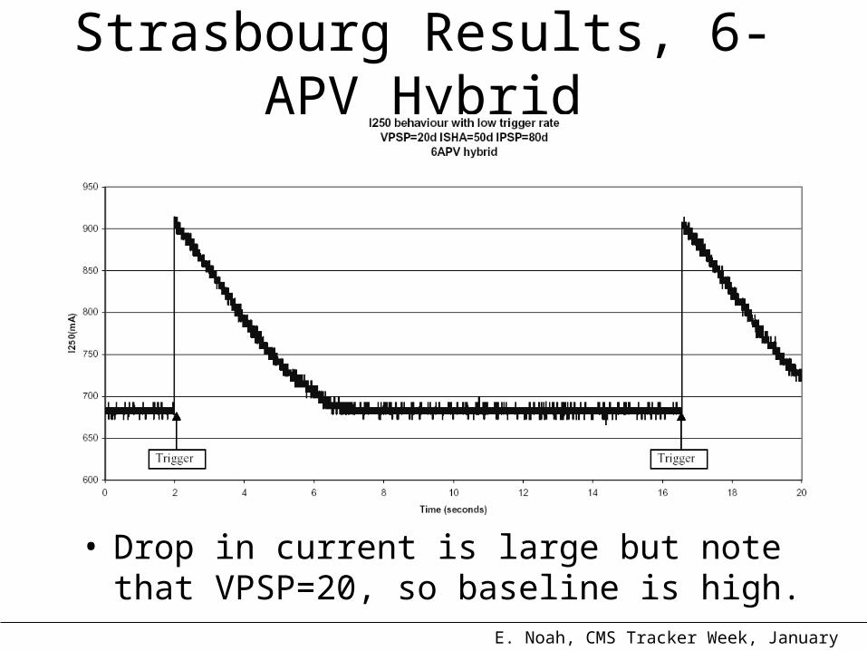
Strasbourg Results, 6-APV Hybrid
• Drop in current is large but note that VPSP=20, so baseline is high.

E. Noah, CMS Tracker Week, January 2003
Strasbourg Results, 4-APV Hybrid
• 4-APV hybrid, same bias register settings as those used at IC. Similar current drop but time constant is much larger.
E. Noah, CMS Tracker Week, January 2003
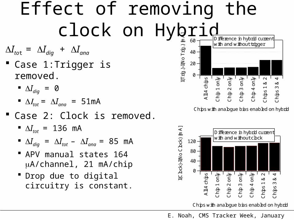
Effect of removing the clock on Hybrid
Itot = Idig + Iana
Case 1:Trigger is removed. Idig = 0
tot = Iana = 51mA
Case 2: Clock is removed. Itot = 136 mA
Idig = Itot – Iana = 85 mA
APV manual states 164 A/channel, 21 mA/chip
Drop due to digital circuitry is constant.
60
40
20
0
I(T
rig.)
-I(N
o T
rig.)
[m
A]
All
4 c
hip
s
Ch
ip 1
on
ly
Ch
ip 2
on
ly
Ch
ip 3
on
ly
Ch
ip 4
on
ly
Ch
ips
1 &
2
Ch
ips
3 &
4
Chips with analogue bias enabled on hybrid
Difference in hybrid currentwith and without trigger
120
80
40
0
I(C
lock
)-I(
No
Clo
ck)
[mA
]
All
4 c
hip
s
Ch
ip 1
on
ly
Ch
ip 2
on
ly
Ch
ip 3
on
ly
Ch
ip 4
on
ly
Ch
ips
1 &
2
Ch
ips
3 &
4
Chips with analogue bias enabled on hybrid
Difference in hybrid currentwith and without clock