Embed Size (px)
Citation preview
E�ective January 2012Supersedes IL29C107M 8/11Instruction Leaflet IL29C107N
Installation Instructions for R-Frame Circuit Breakers and Molded Case Switches
ContentsDescription Page
1. Introduction . . . . . . . . . . . . . . . . . . . . . . . . . . . 22. Installation . . . . . . . . . . . . . . . . . . . . . . . . . . . . 53. Manual Operation . . . . . . . . . . . . . . . . . . . . . . 64. Inspection and Field Testing . . . . . . . . . . . . . . 7
2
Instruction Leaflet IL29C107NE�ective January 2012
Installation Instructions for R-Frame Circuit Breakers and Molded Case Switches
EATON CORPORATION www.eaton.com
WARNING
WARNING DO NOT ATTEMPT TO INSTALL OR PERFORM MAINTENANCE ON EQUIPMENT WHILE IT IS ENERGIZED. DEATH, SEVERE PERSONAL INJURY, OR SUBSTANTIAL PROPERTY DAMAGE CAN RESULT FROMCONTACT WITH ENERGIZED EQUIPMENT. ALWAYS VERIFY THAT NO VOLTAGE IS PRESENT BEFORE PROCEEDING WITH THE TASKAND ALWAYS FOLLOW GENERALLY ACCEPTED SAFETY PROCEDURES.
MISAPPLICATION OR MISINSTALLATION OF ITS PRODUCTS.
The user is cautioned to observe all recommendations, warnings, and cautions relating to the safety of personnel and equipment as well as all general and local health and safety laws, codes, and procedures. The recommendations and information contained herein are based on Eaton experience and judgment, but should not be considered to be all - inclusive or coveringevery application or circumstance which may arise. If any questions arise, contact Eaton for further information or instructions.
EATON IS NOT LIABLE FOR THE
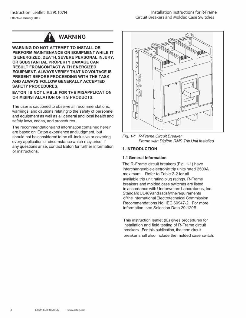
Fig. 1-1 R-Frame Circuit Breaker Frame with Digitrip RMS Trip Unit Installed
1. INTRODUCTION
1.1 General Information The R-Frame circuit breakers (Fig. 1-1) have interchangeable electronic trip units rated 2500A maximum. Refer to Table 2-2 for all
This instruction leaflet (IL) gives procedures for installation and field testing of R-Frame circuitbreakers. For this publication, the term circuit
available trip unit rating plug ratings. R-Framebreakers and molded case switches are listed in accordance with Underwriters Laboratories, Inc. Standard UL489 and satisfy the requirements of the International Electrotechnical Commission Recommendations No. IEC 60947-2. For more information, see Selection Data 29-120R.
breaker shall also include the molded case switch.
WARNING
WARNING DO NOT ATTEMPT TO INSTALL OR PERFORM MAINTENANCE ON EQUIPMENT WHILE IT IS ENERGIZED. DEATH, SEVERE PERSONAL INJURY, OR SUBSTANTIAL PROPERTY DAMAGE CAN RESULT FROMCONTACT WITH ENERGIZED EQUIPMENT. ALWAYS VERIFY THAT NO VOLTAGE IS PRESENT BEFORE PROCEEDING WITH THE TASKAND ALWAYS FOLLOW GENERALLY ACCEPTED SAFETY PROCEDURES.
MISAPPLICATION OR MISINSTALLATION OF ITS PRODUCTS.
The user is cautioned to observe all recommendations, warnings, and cautions relating to the safety of personnel and equipment as well as all general and local health and safety laws, codes, and procedures. The recommendations and information contained herein are based on Eaton experience and judgment, but should not be considered to be all - inclusive or coveringevery application or circumstance which may arise. If any questions arise, contact Eaton for further information or instructions.
EATON IS NOT LIABLE FOR THE
Fig. 1-1 R-Frame Circuit Breaker Frame with Digitrip RMS Trip Unit Installed
1. INTRODUCTION
1.1 General Information The R-Frame circuit breakers (Fig. 1-1) have interchangeable electronic trip units rated 2500A maximum. Refer to Table 2-2 for all
This instruction leaflet (IL) gives procedures for installation and field testing of R-Frame circuitbreakers. For this publication, the term circuit
available trip unit rating plug ratings. R-Framebreakers and molded case switches are listed in accordance with Underwriters Laboratories, Inc. Standard UL489 and satisfy the requirements of the International Electrotechnical Commission Recommendations No. IEC 60947-2. For more information, see Selection Data 29-120R.
breaker shall also include the molded case switch.

3
Instruction Leaflet IL29C107NE�ective January 2012
Installation Instructions for R-Frame Circuit Breakers and Molded Case Switches
EATON CORPORATION www.eaton.com
Fig.2-1 Terminal Installation
Step 1.Install One Rear Connector
Step 2.Install One Set of Heat Sinks
Step 3.Repeat Steps One and Two toAdjacent Poles
Fig.2-2 2500A Rear Connector Instructions
4
Instruction Leaflet IL29C107NE�ective January 2012
Installation Instructions for R-Frame Circuit Breakers and Molded Case Switches
EATON CORPORATION www.eaton.com
Required and shipped with 100% rated frames
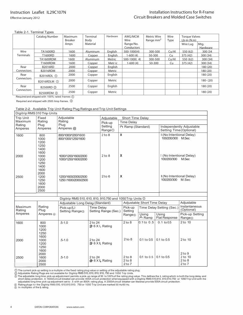
Table 2-2. Available Trip Unit Rating Plug Ratings and Trip Unit Settings Digitrip RMS 310 Trip Units Trip Unit Maximum Rating Amperes
Short Time Delay Adjustable Pick-up SettingRange
Adjustable Rating Plug Amperes @
800/1 000/1 200/1 600 800/1000/1250/1600
Fixed Rating Plug Amperes
800 1000 1200 1250 1400 1600 1000 1200 1250 1400 1600 2000 1200 1250 1600 2000 2500
Time Delay Ramp (Standard) Independently Adjustable
Setting Time (Optional) 2 to 8
2 to 8
2 to 6
X I (No Intentional Delay) 1600
I (No Intentional Delay) 100/200/300 M.Sec
2000 1 000/1200/1600/2000 X
1200/1600/2000/2500 1250 /1600/2000/2500
I (No Intentional Delay) 100/200/300 M.Sec
2500 X
Digitrip RMS 510, 610, 810, 910,750 and 1050 Trip Units Adjustable Long Delay Pick-up
(Standard) Adjustable Short Time Delay AdjustableInstantaneous (Optional) Pick-up Setting
Rating PlugAmperes
Maximum Rating Amperes
Time Delay Setting Range (Sec.)
Time Delay Setting (Sec.) Pick-up SettingRange
2 to 8
2 to 8 2 to 8 2 to 7
Setting Range Using Flat Response
Using Ramp
0.1 to 0.5
0.1 to 0.5
0.1 to 0.5
2 to 10 800 1000 1200 1250 1600 1000 1200 1250 1600 2000 1600 2000 2500
.5-1.0
.5-1.0
.5-1.0
2 to 24 6 X Rating
0.1 to 0.5
2 to 24 6 X Rating
0.1 to 0.5 2 to 10
2 to 9 2 to 10 2 to 8 2 to 7
2000
2500 0.1 to 0.5 2 to 24 6 X Rating
The current pick-up setting is a multiple of the fixed rating plug value or setting of the adjustable rating plug. Adjustable Rating Plugs are not available for Digitrip RMS 510, 610, 810, 910, 750 and 1050 Trip Units.
The adjustable long time pick-up adjustcment permits a pick-- .eulav gulp gnitar eht fo ot %001 05 fo egnar pu This defines the I, rating which is both the long delay and short delay protection. A 1600A circuit breaker can provide 400A circuit protection when equipped with a Digitrip RMS 510,610, 810,910,750 or 1050 Trip Unit with the adjustable long time pick-up adjustment set to .5 with an 800A rating plug. A 2000A circuit breaker can likewise provide 500A circuit protection.
In multiples of the I, rating.Rating plugs for the Digitrip RMS 510, 610.810.910. 750 or 1050 Trip Unit are marked 50 Hz/60 Hz.
Torque Valves Lb-in (N.m)
Catalog Number Maximum Breaker Amps
Terminal Body Material
Hardware AWG/MCM Wire Range/No. Conductors
Metric Wire Range mm²
Wire Type
Wire Lug Mtg. Hardware
TA1600RD 1600 Aluminum English 500-1000(4) 300-500 Cu/Al 550 (62) 300 (34 T1600RD 1600 Copper English 1-600 (4) 50-300 Cu 375 (42) 300 (34)
TA1600RDM 1600 Aluminum Metric 500-1000( 4) 300-500 Cu/Al 550 (62) 300 (34)
Wire Terminals
T1600RDM 1600 Copper Metr ic 1-600 (4) 50-300 Cu 375 (42) 300 (34) B2016RD 2000 Copper English 180 (20) Rear
Connectors B2016RDM 2000 Copper Metric 180 (20)
B2016RDL 2000 Copper English 180 (20) Rear Connectors
B2016RDLM 2000 Copper Metric 180- (20)
B2500RD 2500 Copper English 180 (20) Rear Connectors
B2500RDM 2500 Copper Metric 180 (20)
Required and shipped with 2500 Amp frames.
Table 2-1. Terminal Types
100/200/300 M.Sec
1000/1250/1600/2000
2 to 8
Range1600
Instruction Leaflet IL29C107N Installation Instructions for R-FrameCircuit Breakers and Molded Case Switches
5EATON CORPORATION www.eaton.com
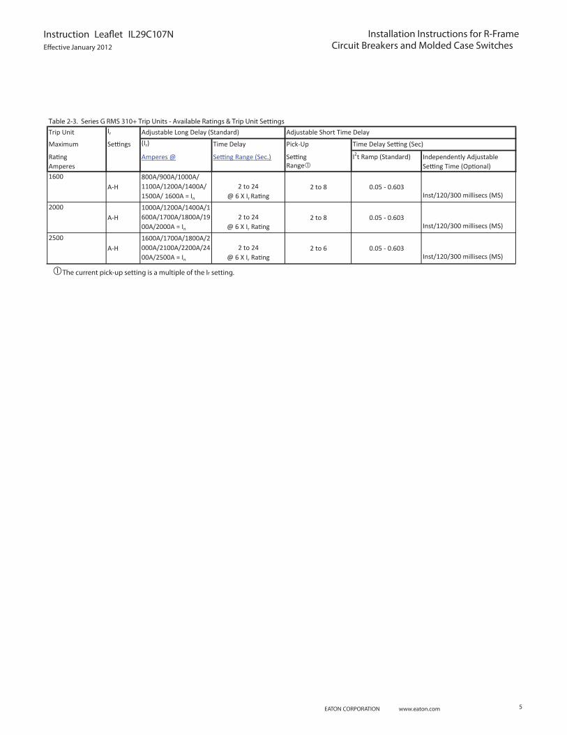
Trip Unit Ir
Maximum Settings (Ir) Time Delay Pick-Up
Rating Amperes @ Setting Range (Sec.) Setting I2t Ramp (Standard) Independently AdjustableAmperes Range Setting Time (Optional)1600
A-H800A/900A/1000A/ 1100A/1200A/1400A/ 1500A/ 1600A = In
2 to 24 @ 6 X Ir Rating
2 to 8 0.05 - 0.603Inst/120/300 millisecs (MS)
2000A-H
1000A/1200A/1400A/1600A/1700A/1800A/1900A/2000A = In
2 to 24 @ 6 X Ir Rating
2 to 8 0.05 - 0.603Inst/120/300 millisecs (MS)
2500A-H
1600A/1700A/1800A/2000A/2100A/2200A/2400A/2500A = In
2 to 24 @ 6 X Ir Rating
2 to 6 0.05 - 0.603Inst/120/300 millisecs (MS)
Table 2-3. Series G RMS 310+ Trip Units - Available Ratings & Trip Unit Settings
Time Delay Setting (Sec)
Adjustable Long Delay (Standard) Adjustable Short Time Delay
The current pick-up setting is a multiple of the Ir setting.

6
Instruction Leaflet IL29C107NInstallation Instructions for R-Frame Circuit Breakers and Molded Case Switches
EATON CORPORATION www.eaton.com
1.2 100 Percent Rated R-Frame Circuit BreakersCRD and CRDC circuit breakers are suitable for continu-ous operation at 100 percent of the frame rating if usedwith the supplied rear connectors B2016EDL and in anenclosurewhich measures at least 21.5 in. high x 18 in. wide x 13 in. deep. Ventilation is not required in an enclo-sure having these minimum dimensions. If cable connec-tions are made to these rear connectors, use only 90°Cwire with based on 75°C conductors and copperonly or terminals.
1.3 2500 Amp R-Frame Circuit BreakersWhen placed in an enclosure with minimum size of 26 in.x 18 in. x 10 in., the enclosure cover must be insulatedwith a barrier on the line end having minimum dimensions of 18 in. x 8 in. x 1/32 in.
.438 (11.13)Dia(4 Use375 Dia. Bolts
MountingCircuit Breaker 7
BreakerHandle
I
4-Pole 19.000(482.60)3-Pole 14.500 (368.30)
Dimensions Inches (Millimeters)
Fig.2-3 CircuitBreaker Mounting Bolt Drilling Plans
Circuit CircuitBreaker BreakerHandle Handle
. . . . . . . . .5.094
(129.39))
CircuitBreakerHandle
17.406(327.81) (442.11)
2. INSTALLATIONThe installationprocedure consists of inspecting thecircuit breaker and, as applicable, installingthe trip unitand rating plug, accessories, and terminals; mounting thecircuit breaker; connecting the line and load conductors; and torquing terminals. Circuit breakers, rating plugs, accessories, mounting hardware, and unmounted termi-nals may be supplied in separate packages. To install thecircuit breaker, perform the following steps. Note: If required, internal accessory installation inany type of circuit breaker should be done before thecircuit breaker is mounted and connected. Refer toindividual accessory instruction leaflets.
2-1.Make sure that the circuit breaker is suitable for theintended installation by comparing nameplate datawith existing equipment ratings and system require-ments. Inspect the circuit breaker for completeness,and check for damage before mounting.
2-2.Remove cover screws and cover.Note:The breaker is equipped with a Cover Interlockfeature, so that when the cover is removed, thebreaker will trip and cannot be reset or operated untilthe cover is replaced and screwed down securely.Note: Instructions for installing the trip unit ratingplug and accessories in the R-Frame circuit breakerare supplied with each item.
2-3. If not already installed, mount trip unit rating plug and accessories (if required) in circuit breaker frame.
2-4. Re-install cover and secure with pan-head screwsprovided. Torque cover screws to 24 in-lbs.
If not already installed, mount terminals as shown inFig. 2-1 or 2-2. If warning label is suppliedwith theterminal, place on upper portion of circuit breakercover.
WARNING
VOLTAGES IN ENERGIZED EQUIPMENT CAN CAUSEDEATH OR SEVERE PERSONAL INJURY. BEFOREMOUNTING THE CIRCUIT BREAKER IN ANELECTRICALSYSTEM, MAKE SURETHERE IS NOVOLTAGE PRESENTWHEREWORK IS TO BEPERFORMED. SPECIAL ATTENTION SHOULD BEPAID TO REVERSE FEED APPLICATIONS ENSURE NOVOLTAGE IS PRESENT.
3 and 4- Pole Circuit Breakers
When installing the R-Frame 2500 amp breaker at 80% of the full rating and inside an enclosure, itis necessary to use coated or painted buswork.
Radius(If Required)
Dimensions in Inches (Millimeters)
Fig. 2-4 Circuit Breaker Escutcheon Dimensions for
2-5.

7
Instruction Leaflet IL29C107N Installation Instructions for R-Frame Circuit Breakers and Molded Case Switches
EATON CORPORATION www.eaton.com
2-6. To mount the circuit breaker, perform the following steps:
a. For individual surface mounting, drill mounting panel using the drilling plan shown in Fig. 2-3. Fordead-front cover applications, cut out cover tocorrect escutcheon dimensions, see Fig. 2-4.
If circuit breaker includes factory or field installed internal accessories, make sure accessory wiring is accessible when the circuit breaker is mounted.
b.
Note: Labels with accessory connection schematicdiagrams are provided on the side of the circuitbreaker.A note should be made of the diagrams if the labels cannot be seen when the circuit breaker ismounted.
c. Position circuit breaker on mounting surface.
Install circuit breaker (mounting hardware notsupplied).
CAUTION
OVERHEATINGCAN CAUSE NUISANCE TRIPPINGAND DAMAGETOTHECIRCUIT BREAKER.WHENALUMINUMCONDUCTORS ARE USED, THEAPPLICATIONOFA SUITABLE JOINT COMPOUNDISRECOMMENDED TO REDUCE THE POSSIBILITY OFTERMINALOVERHEATING.
2-7. Connect line and load conductors and accessory
Note:The circuit breaker is suitable for reverse feed application. Observe warning label on cover before attempting to remove cover.
the circuit breaker is installed, check all mount-ing hardware and terminal connecting hardware forcorrect torque loading. Torque values for line/loadterminals are given in Table 2-1 and on the circuit breaker nameplates.
leads.
3. MANUALOPERATIONNote:The trip unit and rating plug must be installed before attempting to close the circuit breaker.Manual operation of the circuit breaker is controlled by thecircuit breaker handle and the PUSH-TO-TRIP button. The circuit breaker handle has three positions, two ofwhich are shown on the cover with raised lettering toindicate ON and OFF. On the handle, ON, OFF, and trip
i
HandlePositionIndicator
Color: Red - ON-
1 I I I
InternationalTrip Unit Symbols
I-ONRating Plug
Fig. 3-1 CircuitBreaker Manual Controls
are also shown by a color-coded strip for each circuit breaker handle position: red for ON, white for tripped, and green for OFF. (See Fig. 3-1
3.1 Circuit Breaker Reset After an automatic or accessory initiated trip, or a manual PUSH-TO-TRIP operation, the circuit breaker is reset bymoving the circuit breaker handle to the extreme OFFposition.Note: No circuit breaker should be reclosed until thecause of trip is known and the situation rectified.
PUSH-TO-TRIP ButtonThe PUSH-TO-TRIP button checks the circuit breaker tripping function and may be used to periodically exercise the operating mechanism. The button is designed to beoperated by finger pressure.
Interchangeable Trip UnitsInformationfor the Digitrip RMS trip units is shown inTable 2-2.For additional information on interchangeable trip units,refer to the following instruction leaflets:
Digitrip RMS 310 ........................................... I.L.Digitrip RMS 51 0 ............................................. I.L.29-885Digitrip RMS 610 ............................................. I.L.29-886Digitrip RMS 810 ............................................. I.L.29-888Digitrip RMS 910 ............................................. I.L.29-889Digitrip OPTIM 750 or 1050........................... I.L. 29C891
d.
3.3
3.2
White TRIP
Controls
I - OFF
Series G RMS 310+ ......................................... IL01210003E 29C883

8
Instruction Leaflet IL29C107NInstallation Instructions for R-Frame Circuit Breakers and Molded Case Switches
EATON CORPORATION www.eaton.com
4. INSPECTION AND FIELD TESTING R-Frame molded case circuit breakers are designed toprovideyears of almost maintenance-free operation. The following procedure describes how to inspect and test a circuit breaker in service.
InspectionCircuit breakers should be inspected periodically.Thisinspection can best be done during normal equipment maintenance periods when no voltage to the equipment isavailable.The inspection should include the followingchecks 4-1 through 4-9.
A
WARNING
VOLTAGES IN ENERGIZED EQUIPMENT CAN CAUSESEVERE PERSONAL INJURY OR DEATH. BEFOREINSPECTING THE CIRCUIT BREAKER IN ANELECTRICAL SYSTEM, MAKE SURE THE CIRCUITBREAKER IS SWITCHED TO THEOFF POSITION ANDTHATTHERE IS NOVOLTAGE PRESENTWHEREWORK IS BEING PERFORMED. SPECIAL ATTENTIONSHOULD BE PAID TO REVERSE FEED APPLICATIONSTO ENSURE NO VOLTAGE IS PRESENT.
CAUTION
SOME COMMERCIAL CLEANING AGENTS WILLDAMAGETHE NAMEPLATESOR MOLDED PARTS.MAKE SURE THATCLEANING AGENTS ORSOLVENTS USEDTO CLEAN THE CIRCUIT BREAKERARE SUITABLE FOR THE JOB.
4-1. Remove dust, dirt, soot, grease, or moisture from the surface of the circuit breaker using a lint-free dry cloth, brush, or vacuum cleaner. Do not blow debrisinto circuit breaker. If contamination is found, look forthe source and eliminate the problem.
be sure that the mechanical linkages are free and donot bind. If mechanical linkages are not free, replacecircuit breaker.
4-3. With the circuit breaker in the ON position, press the PUSH-TO-TRIP button to mechanically trip the circuit breaker.Trip, reset, and switch circuit breaker ON several times. If mechanism does not reset each time the circuit breaker is tripped, replace the circuit breaker.
4-2. Switch circuit breaker to ON and OFF several times to
4-4. Check base, cover, and operating handle for cracks, chipping, and discoloration. Circuit breakers should be replaced if cracks or severe discoloration is found.
Check terminals and connectors for looseness orsigns of overheating. Overheating will show asdiscoloration, melting, or blistering of conductorinsulation, or as pitting or melting of conductorsurfaces due to arcing. If there is no evidence ofoverheatingor looseness, do not disturb or tighten the connections. If there is evidence of overheating,terminations should be cleaned or replaced.Beforere-energizing the circuit breaker, all terminations and cable should be refurbished to the condition whenoriginally installed.
4-6. Check circuit breaker mounting hardware, and tighten if necessary.
4-7. Check area where circuit breaker is installed for anysafety hazards, including personal safety and fire hazards. Exposure to certain types of chemicals can cause deterioration of electrical connections.
operation of circuit breakers with Digitrip RMS 310 trip units can be field tested using the Seltronic test kit, Catalog Number SKT2. (See Selection Data 29-120R).
operation of circuit breakers with Digitrip RMS 510, 610, 810, and 910 trip units can be field tested on a bench using the Auxiliary Power Module, Cata-log Number PRTAAPM.The Digitripm OPTIM 750, and 1050 trip units also require a Digitrip OPTIMIZER forbench testing.
Field Testing Any field testing should be done in accordance with NEMA Standards Publication AB4-1990.
4-5.
4-8.The
4-9.The
4-10. The operation of circuit breakers with Series G RMS 310+ trip units can be field tested using the G Series test kit general assembly number: 70C1056G54.
Instruction Leaflet IL29C107N Installation Instructions for R-Frame Circuit Breakers and Molded Case Switches
NOTES:
9 EATON CORPORATION www.eaton.com
Eaton CorporationElectrical Group1000 Cher rington ParkwayMoon Township, PA 15108United St ates877-ETN-CARE (877-386-2273)Eaton.com
© 2012 Eaton CorporationAll Rights R eservedPrinted in US APublication No. IL29C1 07N / TBG0 00683Part No. 6645C84H14January 2012
Eaton is a registered trademark of Eaton Corporation.
All other trademarks are property of their respective owners.
Instruction Leaflet IL29C107N Installation Instructions for R-Frame Circuit Breakers and Molded Case Switches
The instructions for inst allation, testing , maintenance, or repair herein are provided for the use of the product in general commercial applications and may not be appropriate for use in nuclear applica-
to replace, amend, or supplement these instructions to qualify them for use with the product in saf ety-related applications in a nuclear facility.
This Instr uction Booklet is published solely for information purposes and should not be considered all-inclusive. If further information is required, you should consult an authorized Eaton sales represent a-tive.
The sale of the product shown in this literature is subject to the terms and conditions outlined in appropriate Eaton selling policies or other contract ual agreement between the parties. This literature is not intended to and does not enlarge or add to any suc h contract. The sole source governing the rights and remedies of any purchaser of this equipment is the contract between the purchaser and Eaton.
NO WARRANTIES, EXPRESSED OR IMPLIED, INCLUDING WARRANTIES OF FITNESS FOR A PARTICULAR PURPOSE OR MERCHANTABILITY, OR WARRANTIES ARISING FROM COURSE OF DEALING OR USAGE OF TRADE, ARE MADE REGARDING THE INFORMATION, RECOMMENDATIONS, AND DESCRIPTIONS CONTAINED HEREIN.
In no event will Eaton be responsible to the purchaser or user in contract, in tort (including negligence), strict liability or other wise for any special, indirect, incidental or consequential damage or loss whatsoever, including but not limited to damage or loss of use of equipment, plant or power sy stem, cost of capital, loss of power, additional expenses in the use of existing power facilities, or claims against the purchaser or user by its customers resulting from the use of the information, recommendations and description contained herein.