Embed Size (px)
DESCRIPTION
top drive
Citation preview

Contents
1 Safety cautions...........................................................................................1
2 Safety operation prompts.........................................................................2
2.1 Safety operation prompts of electricity......................................................................2
2.2 Safety operation prompts of hydraulic pressure.......................................................3
2.3 Safety operation prompts of well control...................................................................4
3 Main technical parameters........................................................................5
3.1 Basic parameters..........................................................................................................5
3.2 Drilling parameters......................................................................................................5
3.3 Motor parameters........................................................................................................5
3.4 Cooling fan...................................................................................................................6
3.5 Hydraulic disc brake...................................................................................................6
3.6 Electrical control system.............................................................................................6
3.7 Pipe processing unit.....................................................................................................6
3.8 Hydraulic control system............................................................................................7
4 Structure and working principle..............................................................7
4.1 Direct-drive drilling motor assembly.........................................................................9
4.2 Pipe processing unit...................................................................................................14
4.3 Balance system...........................................................................................................29
4.4 Guide rail and pulley.................................................................................................30
4.5 Electric drive and control system.............................................................................33
4.6 Electric drive and control system.............................................................................42
5 Operating instructions.............................................................................52
5.1 Check before startup.................................................................................................52
5.2 Operation of electric system......................................................................................53
5.3 Operation of hydraulic system..................................................................................53
5.4 Driller console control...............................................................................................54
6 Drilling steps.............................................................................................65
I

6.1 Tripping in /out..........................................................................................................65
6.2 Drilling work condition.............................................................................................66
6.3 Back reaming..............................................................................................................68
6.4 Run casing..................................................................................................................69
6.5 Well control.................................................................................................................69
6.6 Jarring.........................................................................................................................70
II

DQ450DBZ DIRECT-DRIVE TOP DRIVE USER’S MANUAL
1 Safety cautions
Besides to introduce the contents of main body, this manual has also included the
following contents, such as 'note' , 'caution' and 'warns', they are marked and used for
prompting the possible danger which may caused in operation, the symbolic meanings
are as follows:
Supplement for relevant safety items
Prompting for accident which may caused
Prompting for accident which may caused easily
Only qualified and experienced personnel are allowed to conduct installation and
commissioning to top drive unit, prior to operation please read and follow this
specification and related technical documents carefully.
The personnel who accepted the training about drilling operation and drilling safety
are allowed to conduct the installation, commissioning and close to the system device. Be
sure to keep in mind that uses the proper protective articles such as gloves and safety
wares.
In this specification, literal contents displayed with the symbol of
are executive components of electrical system such as button and
switch and so on.
Please read the specification before installation, commissioning,
operation and maintenance of electrical system. Due to the
continuous renewal of technology and serialization of products,
check up the product codes which must be the same as the ones on
the cover, and to make sure consistency of product and technical
documents.
Never try to install, test, operate and maintain the electrical system
without profession and training; otherwise, it may lead to the
personal injury or equipment accident. Maintain and repair the
equipment in stopped status.
1
Note
Caution
Warns
Note
Caution
Warns

DQ450DBZ DIRECT-DRIVE TOP DRIVE USER’S MANUAL
2 Safety operation prompts
This manual mainly has described the structure, composition and functions of each
part, and also described the application and operation of top drive as the key points.
Please refer to the 'electric manual' and 'hydraulic pressure manual' if the fault diagnosis
and repairing had be involved.
The operators can operate the equipment after they read the manual carefully and
being well-trained.
2.1 Safety operation prompts of electricity
Pay attention to following items before operation of equipment and electrical
system:
1) The commissioning and maintenance of electrical system should be conducted by
professional.
2) Read the 'electrical system manual' and 'illustrated pictorial catalog of electrical
system' carefully, and know well the electrical wiring diagram.
3) The professional tools should be provided and protected correspondingly.
4) Cut off the power switch before all operation had finished, and hang the
signboard of 'non-switch on'.
5) Prior to disconnecting electrical connection, verify that wire (cable) and
connecting terminal are properly labeled to ensure proper reconnection.
6) Never try to repair or remove any electrical elements, and pull out or insert the
cable plugs with electricity.
7) Never try to open the anti-explosion control cabinet or driller’s station with
electricity under the circumstance of flammable gas.
8) Never replace the DC insurance between DC bus and inverter before the rectifier
operation and DC bus voltage cut down below safe range (DC 24V), otherwise, it may
cause human injury and equipment damage.
9) To avoid the faulty operation, separating the switch to main circuit breaker of
rectifier cabinet when repair the rectifier, inverter or motor
10) Do not detect the isolation of rectifier and inverter by megger, otherwise, high
2

DQ450DBZ DIRECT-DRIVE TOP DRIVE USER’S MANUAL
testing voltage will damage the equipment.
11) Keep the pressure of protective gas when power on to driller’s station, recover
the pressure as soon as possible or stop drilling and cut off the control power supply of
driller’s station when the protective gas loss of pressure.
12) It is forbidden to relieve safety chain of any software and hardware. Recover the
function of linkage by bypass after troubleshooting.
13) Do not start the driver and other control power supply before temperature
reduction and dehumidification of air conditioner when the temperature is more than
40℃, humidity more than 95% or there is condensation.
14) Ensure that there is no condensation in electric control cabinet when the main
power supply powered on again after cut off for half an hour.
15) It is forbidden to open the electric control room for a long time or be opened
frequently when the temperature of it is under external environment temperature in humid
condition; otherwise, there is condensation on electrical equipment.
2.2 Safety operation prompts of hydraulic pressure
Pay attention to following items before operation of equipment and hydraulic
system:
1) Read the 'hydraulic system manual' carefully, and know well the schematic
diagram of hydraulic system.
2) Cut off the electrical control.
3) Take off the systematic pressure slow by unloading valve, and make sure there is
no pressure in pipeline.
4) Prior to disconnecting pipeline, verify that connecting parts are properly labeled to
ensure proper reconnection.
Close the valves in the system before dismantling the hydraulic
pipeline, prepare the proper container, cotton yarn and greasy
blockage to avoid residual hydraulic fluid outflow to pollute the
equipment and environment when open the pipeline.
Due to the temperature of hydraulic device and hydraulic fluid is
3
Note
Caution

DQ450DBZ DIRECT-DRIVE TOP DRIVE USER’S MANUAL
high, so they need to be cooled for a long time to recover the normal
temperature.
2.3 Safety operation prompts of well control
Pay attention to following items in installation and application of top drive, and
understand the condition of strata pressure and requirements of well control at any time.
1) Read carefully and understand the design requirements of drilling and technical
requirements of well control.
2) Carry out related industrial standards and regulations as per the requirements of
recommended practices under the circumstance of hi-pressure hydrocarbon reservoir or
harmful gas such as H2S、SO2 etc during drilling.
3) During drilling in the hydrocarbon reservoir, keep the equipment in good condition,
check and drill the operation of IBOP etc operation of well control during shift every day,
and process it timely if there are problems.
4

DQ450DBZ DIRECT-DRIVE TOP DRIVE USER’S MANUAL
3 Main technical parameters
3.1 Basic parameters
Model of top drive DQ450DBZ
Drive mode (AC VFD)
Nominal drilling depth 7000m
Max. load 4500kN(500tons)
Working pressure of hydraulic system 16MPa
Drift diameter of centre tube 75mm (3in)
Rated working pressure of centre tube 35MPa (5000psi)
Dead weight 15.8t
Guide rail weight 9.6 t
Working height 5.7m
Electric power supply 575~690VAC (50/60Hz)
Rated current 774A
Rated power 580kW
Ambient temp. -35℃~50℃
Altitude ≤1000m
3.2 Drilling parameters
Nominal drilling depth 7000m
Range of speeds 0~220r/min continuously adjustable
Working torque 50kN.m
Max. torque 75kN.m
3.3 Motor parameters
Rated power 580kW
Rated voltage 575VAC
Rated frequency 16.9Hz
Rated current 774A
5
DQ450DBZ DIRECT-DRIVE TOP DRIVE USER’S MANUAL
Rated speed 125r/min
Max. speed 220r/min
3.4 Cooling fan
Rated power 5kW
Rated voltage 380V
Rated frequency 50Hz
Rated current 13.1A
Rated speed 3190r/min
3.5 Hydraulic disc brake
Brake torque 50kN.m
Cylinder working pressure 10MPa
3.6 Electrical control system
Input voltage of VFD 575~690VAC (50/60Hz)
Output frequency of VFD 0~87.1Hz
Oil temp. alarm of hydraulic power 70℃
Alarm for low level in oil tank of hydraulic power <180mm,>400mm
3.7 Pipe processing unit
Speed of rotating head 3~8r/min (adjustable)
Working pressure of hydraulic motor 14MPa
Upper IBOP (remote)
Lower IBOP (manual)
Clamping range of back-up tong 86~216mm
Max. break out torque 75kN.m
Angle of inclination for elevator link lean 35° forward and 50° backward
6

DQ450DBZ DIRECT-DRIVE TOP DRIVE USER’S MANUAL
3.8 Hydraulic control system
Working pressure 16MPa
Working flow 28L/min
Voltage of electromotor 600 VAC
Power of electromotor 11kW
Speed of electromotor 1460r/min
4 Structure and working principle
DQ225DBZ/DQ450DBZ top-drive drilling system mainly consists of direct-drive
drilling motor assembly, pipe processing unit, electric drive and control system,
hydraulic drive and control system, driller console, folding single guide rail and
sectional carriage.
7

DQ450DBZ DIRECT-DRIVE TOP DRIVE USER’S MANUAL
DQ225DBZ/DQ450DBZ integral structure diagram
8
Counterbalance system
Washpipe packing assembly
Motor housing
Pipe processing unit
Hydraulicsystem

DQ450DBZ DIRECT-DRIVE TOP DRIVE USER’S MANUAL
Detailed structure diagram
4.1 Direct-drive drilling motor assembly
The direct-drive drilling motor assembly mainly consists of AC variable
9
Bail
S-pipe
Gooseneck
IBOP (Inner Blowout Preventer)Elevator link
Main shaft
Traction motor
Back-up clamp
Bell guide
Elevator link clampLocking device
Powered rotating head
Tilting cylinder, elevator link
Hydraulic oil pump
Hydraulic valve set
Main motor blower
Centre tube
Disc brake mechanism
Lift box
Hydraulic oil tank, top drive
Systematic accumulator
Hydraulic electric control box
Electric control box, main motor, top drive

DQ450DBZ DIRECT-DRIVE TOP DRIVE USER’S MANUAL
frequency traction motor, bail, washpipe packing assembly and hydraulic disc brake
in the lifting box located on the top of motor. The bail is fixed on the lifting box body,
and upper end of it connected with travelling block. The centre shaft of AC variable
frequency motor is the traction shaft of top drive, and the operation such as rotary
drilling, makeup & breakout and mud circulation can be conducted by driving the top
drive to make sure the normal drilling operation.
Direct-drive drilling motor assembly
4.1.1 Main motor and air-cooled motor
The rated speed of DQ450DBZ direct-drive top drive is below 125r/min at
frequency of 16.9Hz. The traction motor can provide continuous torque of 26000N.m,
and the rated speed of it is above 125r/min at frequency of 16.9Hz, continuous power
10
Bail
Washpipe packing assembly
Lift box
Bail pin
Electric control box, main motor
Blower of main motor
AC VF motor
Hydraulic disc brake

DQ450DBZ DIRECT-DRIVE TOP DRIVE USER’S MANUAL
of 580kW can also be provided, and realize stepless speed regulating by frequency
speed control system.
Main motor is variable frequency and variable speed asynchronous motor and
adopts firm and high-quality carbon structural steel welded type housing with high
strength, decreased the vibration during running of motor. Class of insulation is grade
H, and the lubrication grease adopts Arcanol L135V (FAG) or special selection as per
special environment.
Limit values of rated output torque are limited by current, output torque is in
direct proportion to electric current.
It is equipped with air-cooled motor at the right side of main motor; the blower is
driven by three-phase current asynchronous motor, after rotating of blower, it sucks
the wind from exhaust inlet of lower cover and discharged from air outlet of air-duct
blower through air outlet of motor skid and air duct inside main motor. Reliable
ventilated is guaranteed with the simple structure and durability of the design.
It is equipped with wind pressure switch on the top of main motor terminal for
checking whether the wind pressure is normal and rotating direction of blower is
correct. There are 2 temperature sensors PT100 are embedded in winding head inside
the motor, one is for detecting the temperature of main motor, and the other one is for
standby.
4.1.2 Brake apparatus
Shaft-extension end on the top of main shaft of main motor equipped with
hydraulic operating disc brake to realized brake through 2 pairs of brake cylinders
clamping the brake disc, its braking energy is in direct proportion to imposed
pressure. The structure of brake apparatus is as shown:
11

DQ450DBZ DIRECT-DRIVE TOP DRIVE USER’S MANUAL
Brake apparatus
Every brake body equipped two reset springs to make the brake friction plate
reset automatically when releasing the brake. Abrasion loss of brake friction plate can
compensated automatically through increasing the piston stroke.
The functions of brake apparatus are as follows:
1) Bear the reactive torque of drilling tools in downhole;
2) When the drill pipe get stuck in down hole, drilling tools will be rebounded
quickly if the motor stopped, so at the moment, skid the drill tools to avoid inversion
and tripping.
3) Brake the motor when it is out of order.
4.1.3 Washing pipe assembly
Washing pipe assembly is installed
between main shaft and gooseneck,
maintain the washing pipe packing
assembly periodically to extend its
service life.
Method to change washing pipe:
1)Before install a complete set of
12
Washing pipe assembly
Disc brake tongBrake disc
Main shaft
Encoder
Expansion sleeve
Washing pipe assembly

DQ450DBZ DIRECT-DRIVE TOP DRIVE USER’S MANUAL
washing pipe, thread connector and
front contact surface shall be cleaned
and spread on grease. Remove cover
(Cover for storage).
2)Check if o-ring is in trough or
not. Remove o-ring if necessary, spread
on grease in trough to prevent o-ring
falls down. Put mud pipe on main shaft
with lower seal box carefully.
The thread of upper and
lower seal boxes is left-hand one.
3 ) Lift the upper seal box and
screw it in swivel goose, and screw the
lower seal box in the main shaft.
4 ) Screw the upper seal box by
spanner. It is considered that the thread
was tightened when there is no relative
motion; screw the lower seal box with
the same way. Take away all tools and
auxiliaries after filling the lubrication
grease through lubricating nipple 4.
The method for replacing the seals in washing pipe:
Grease the seals in washing pipe during drilling. The method of replacing washing
pipe and seals is the same as the one of swivel. The washing pipe is fixed by 2 nuts
and they are left-hand thread. Tighten or loosen them by hammer, plunger chip or
similar tools.
4.1.4 Bail
As the integral swivel bail and the main
13
Logging channel plugWashpipe assembly
Caution

DQ450DBZ DIRECT-DRIVE TOP DRIVE USER’S MANUAL
bearing parts of top drive, bail bears the overall
weight of top drive, it connected with lifting box
body through bail pin, and upper end is hanged on
the traveling block or hook.
The capacity of bail for DQ450DBZ top drive unit
is 4500kN(500tons) and conforms to the standard
hook load of API8A/API8C, and performance
indicators reached safety lifting load standard of
API.
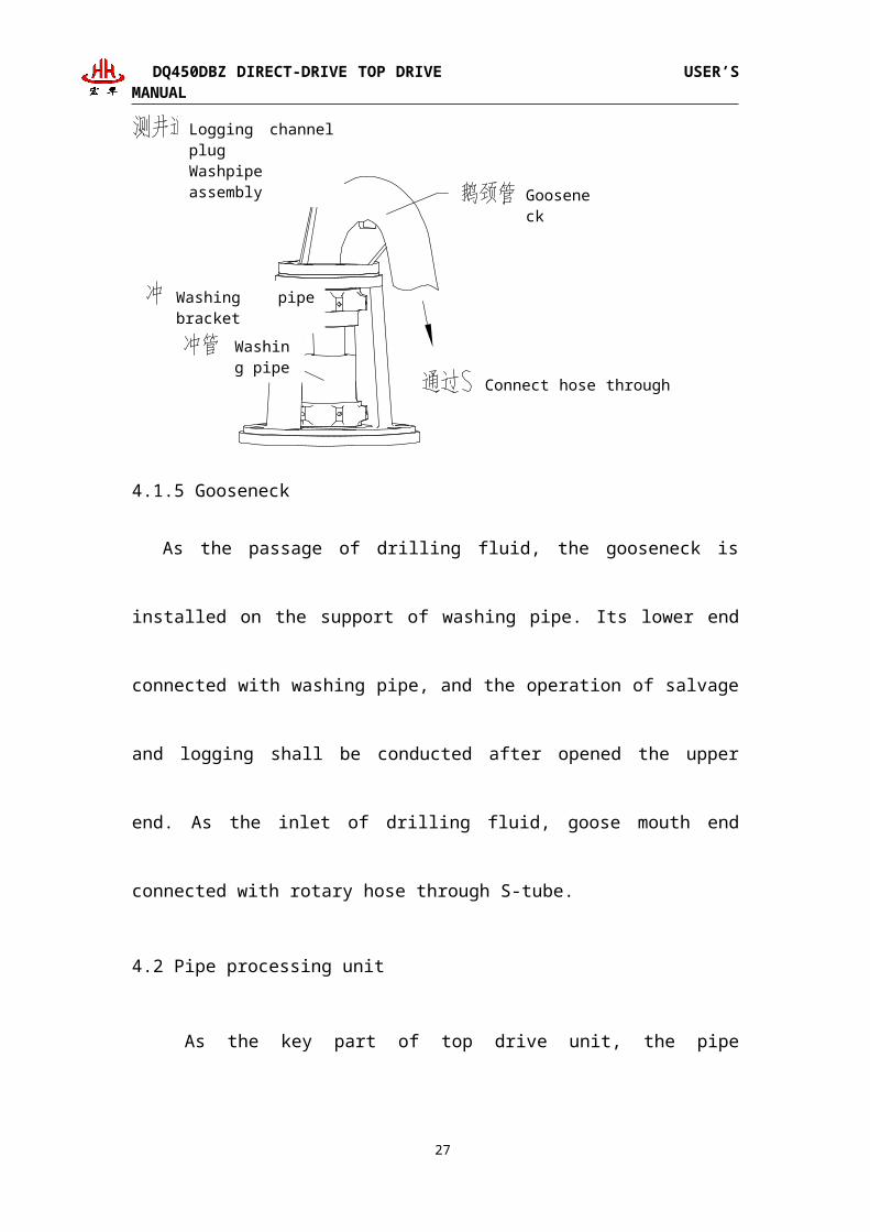
4.1.5 Gooseneck
As the passage of drilling fluid, the gooseneck is installed on the support of
washing pipe. Its lower end connected with washing pipe, and the operation of
salvage and logging shall be conducted after opened the upper end. As the inlet of
drilling fluid, goose mouth end connected with rotary hose through S-tube.
4.2 Pipe processing unit
As the key part of top drive unit, the pipe processing unit can increase the
automaticity of the operation of drilling. It consists of back-up tong, IBOP, control
mechanism, leaning device, elevator link and elevator. The structure is as shown:
14
Washing pipe
Gooseneck
Washing pipe bracket
Connect hose through S-tube
Logging channel plugWashpipe assembly

DQ450DBZ DIRECT-DRIVE TOP DRIVE USER’S MANUAL
Pipe processing unit
Pipe processing unit served for tripping in/out, and running casing etc operation.
The rotating head can catch and release the drill pipe in any arbitrary direction
through driving by hydraulic motor. The operation of taking out the drill pipe from
mouse hole and connecting stands can be realized by leaning forward and backward
of elevator link tilting device. The back-up tong can finish the operation of makeup,
breakout and clamping, and conduct the makeup and breakout through motor. The
IBOP (automatic) and IBOP (manual) are connected at the lower end of main shaft,
and mud passage inside drill stem shall be opened quickly and remotely.
4.2.1Powered rotating head
The upper end of powered rotating head connected with bull gear disc, and the
lower end located on bearing nut of the bearing seat. The relative motion is conducted
between powered rotating head and main shaft, and the structure is as shown. The
15
Powered rotating headPowered rotating head motor
Main shaft
Elevator link
Elevator link clamp
Back-up tong
BOP (manual)
IBOP (Inner Blowout Preventer)
Locking device
Tilting cylinder, elevator link
Bell guide

DQ450DBZ DIRECT-DRIVE TOP DRIVE USER’S MANUAL
rotation of powered rotating head is driven by bull gear disc which driven by
hydraulic motor and the speed of hydraulic motor is adjusted by speed regulating
valve. Generally, setting speed of powered rotating head is 5~8 r/min. The powered
rotating head can rotate clockwise and anticlockwise of 360° and also drive the
elevator link and elevator to adopt to operating requirements of different directions.
The special thing which deserves to be
mentioned is that the powered rotating
head located on the bearing nut which
connected with main shaft through
bearing seat. It has the stabilized
bearings in it; so, it can bear the drill
stem load and radial force of makeup and
breakout immediately during tripping
in/out or running casing, but the powered
rotating head does not bear any load
during drilling.
Powered rotating head is also the
pass way of hydraulic oil, rotating head
connects with many hydraulic
actuating mechanisms. Because
360°rotation is needed, rotation seal
and ring oil way are fixed inside,
hydraulic oil flows from inside to
achieve oil inlet from lower barrel and
oil outlet from rotating head, transfer
hydraulic oil way from motionless to
movement.
4.2.2 IBOP
The function of IBOP (Inner Blowout Preventer) is to avoid the blowout. Close
16
Powered rotating head
Mainshaft
Hydraulic motor
Bull gear disc
Lowershell
Hang-off padeye,elevator link
Locking device, gear disc
Powered rotating head

DQ450DBZ DIRECT-DRIVE TOP DRIVE USER’S MANUAL
the IBOP and cut off the interior passage of drill stem in order to prevent the well kick
or blowout when the pressure in well is higher than internal pressure of drill stem.
The IBOP consists of upper IBOP (remote) and lower IBOP (manual).The upper
IBOP (remote) connected with main shaft of power swivel, and lower IBOP (manual)
connected with saver sub which connected to drill pipe during drilling.
17

DQ450DBZ DIRECT-DRIVE TOP DRIVE USER’S MANUAL
IBOP structure
Install the locking device between connectors to prevent the screw thread
between main shaft and IBOP connector from loosing during break out of top drive.
18
Pretecting connector
Locking device
Manual BOP
Locking device Auto BOP
Cut off casing
Rocker arm assembly
Cover and fixing bolt
Cylinder cut off
Fixing boltSupport seat of cylinder cut off
Locking device Main shaft

DQ450DBZ DIRECT-DRIVE TOP DRIVE USER’S MANUAL
Its structure is as
The reverse of direction of IBOP (remote) will be conducted through operating
the hydraulic cylinder in order to open and close the IBOP device conveniently at
19
Screw thread locking device, BOP
Bolt
Upper flange
Lower flange
Taper sleeve

DQ450DBZ DIRECT-DRIVE TOP DRIVE USER’S MANUAL
driller console. Cylinder support seat connects two groups of upper and lower
trolleys, the two groups of upper and lower trolleys touch edge of casing cutting off,
inner hexagonal rocker arm assembly which correspond to IBOP is embedded in
casing, and drive rocker arm assembly mechanism inside of casing cutting off rotate
to achieve cutting off of IBOP. The entire mechanism can switch IBOP on and off on
driller's console.
The cylinder push the IBOP sleeve upward, rotate the crank and rotating pin and
close the ball valve of IBOP when there is a electric signal from drill floor to the
IBOP return circuit of hydraulic control valve set, conversely, if the cylinder push the
IBOP sleeve downward, the ball valve of IBOP opened. The connecting bottom end
between cylinder and sleeve is contacting roller, so the rolling motion of sleeve which
rotated with main shaft and roller on the piston rod of cylinder can be guaranteed.
Breakdown drawing of IBOP remote controlling structure
Good adjustment of IBOP cylinder is very important to operation of IBOP in a
20
Cylinder cutting off
Guiding rod
Retainer ring
Grease nipple
WasherNut
Support seat
Fixing bolt of guiding rod
Casing
Drum
Drum shaft

DQ450DBZ DIRECT-DRIVE TOP DRIVE USER’S MANUAL
correct mode. IBOP cylinder should be checked frequently. It should be checked more
frequently after maintenance or after valves, sleeves and cranks are replaced. Oil
supply pressure of IBOP cylinder is adjusted to 40bar. Pressure is checked by
operating handle on valve block. Pressure can be displayed on pressure gauge in
hydraulic schematic diagram. Pressure can be adjusted by block valve of IBOP.
Steps of adjusting IBOP cylinder:
1) detach cylinder from suspension board;
2) detach sleeves and cranks from BOP;
3) open BOP by a hexagonal head wrench and be sure that BOP has been
opened;
4) place crank hexagon head in inner hexagon of IBOP;
5) supply pressure oil to cylinder so that piston rod is completely stretched out
before cylinder installation;
6) fix cylinder on suspension board with bolts after piston rod is completely
stretched out;
7) if plastic gasket on cylinder and cam sleeve contact or have 3-5mm interval,
position of cylinder is adjusted in place when opening blowout preventer valve; if
interval between the two is more than 5mm, bracket must be adjusted by rotating
piston rod of cylinder clockwise.
Before adjustment, unscrew holding screw on bracket.
8) remove cylinder and sleeves/cranks, close BOP and make sure that the BOP
has been closed, and reinstall sleeves/cranks;
9) before cylinder installation, supply pressure oil to cylinder so that piston rod is
completely retracted;
10) reinstall cylinder;
11) if trolley contacts with flange end part of sleeve, adjustment of bracket and
cylinder is completed;
12) release pressure inside cylinder, install cylinder on suspension board;
13) operate IBOP cylinder on operating panel to open blowout preventer valve
and then retract plastic gasket/cylinder 5mm.
21
Caution

DQ450DBZ DIRECT-DRIVE TOP DRIVE USER’S MANUAL
If this distance is too small, wearing of plastic gasket will be caused during
drilling. If this distance is too large, trolley contacts with lower end of flange of
sleeve, it will close blowout preventer valve locally and the BOP is excessively worn.
When BOP is opened, plastic gasket and trolley must have proper interval with other
parts. When BOP is closed, trolley is always pressed at lower end of sleeve flange.
Steps of replacing protection joint and IBOP:
Method 1: use torque tong:
1) during breakout of protection joint with torque tong, install forceps holder
with an outer diameter of 6 5/8'' and tool joints with an outer diameter of 7 3/4'';
2) lift torque tong upward to needed height (about 220mm);
3) place torque tong mode switch at manual position on control panel;
4) break out twice;
5) screw off protection joint with hands;
6) install new protection joint and make up.
Method 2: use drill pipe tong;
1) take down four hydraulic quick connectors on oil block of torque tong;
2) remove torque tong from guide rod;
3) lower torque tong to drill floor;
4) retract guide rod if necessary;
5) break out with drill pipe tong; in order to detach cock and install IBOP or
intermediate joint, first remove IBOP sleeve and cylinder.
When free end of joint is not fixed on rotary table, do not use drill
pipe tongue.
Recommended makeup torque of IBOP and protection joint is 63000N.m
(47000ft.lbs).
Steps of detaching IBOP and cylinder:
1) pull out two pins, remove sleeve and open;
2) remove crank;
3) remove bolts on cylinder and then take off cylinder.
Under normal drilling condition and when main shaft rotates, do not
22
Caution
CautionCaution

DQ450DBZ DIRECT-DRIVE TOP DRIVE USER’S MANUAL
operate IBOP to prevent pump from suffocation; only when blowout
and kick generate, can IBOP be operated to close IBOP. Generally, it
is not allowed to close IBOP during trip, otherwise IBOP may be
closed incompletely at critical moments of blowout and kick and
grave accidents are caused. Check all indicator lamps of operation
panel and see whether IBOP button is at open position before
drilling. Remember to open IBOP first and then open mud pumps.
For high flow rate, high pressure seal and high stress load applied to drill pipe,
remote control IBOP is a good switching device.
4.2.3 Tilting device
Elevator link tilting device is an automatic device designed for increasing human-
friendly functions of top drive device and reducing labor intensity of drillers on drill
floor. It is mainly used for moving elevator to position above mouse hole to lift single
in mouse hole. Single is conveniently and quickly connected, derrick man on monkey
board does not need to lean hook against monkey board when connecting stands, and
stands grasping operation is achieved by forward tilt. When drill pipe on drill floor is
drilled down, top drive can tilt backward to approach surface of drill floor as much as
possible by tilting device. Usually, backward tilt angle is relatively large. The forward
and backward tilt of elevator link tilting device can further help top drive to
conveniently guide drill pipe into backup tong horn mouth easily for realizing
breakout operation.
23

DQ450DBZ DIRECT-DRIVE TOP DRIVE USER’S MANUAL
Elevator link tilting device
Above drawing is elevator link tilting device of top drive. It comprises two
hydraulic cylinders with the same specification and their accessories (including
elevator link, hydraulic joints and pipelines). One end of cylinder is connected with
cylinder support plate while the other end is connected with elevator by pin. The joint
of tilting cylinder and elevator link of top drive can be adjusted by loosening elevator
link for changing forward and backward tilt angles. Forward and backward oscillation
of elevator link is realized by extension and retraction motions of cylinder; maximum
extension length of cylinder is maximum forward tilting position of elevator link of
top driver; and complete retraction of cylinder is maximum backward tilting position
of top drive. Elevator link can automatically return to intermediate position through
suspension function under the action of dead weight.
Forward tilt angle is 35 degrees, backward tilt angle is 50 degrees, and maximum
24
Supporting plate Rotating
head
U bolt
Bail
Dump ramForerake
Hypsokinesis
Elevator

DQ450DBZ DIRECT-DRIVE TOP DRIVE USER’S MANUAL
ground forward tilting distance and maximum ground backward tilting distance are
related with length of elevator link.
Elevator link tilting device mainly comprises parts of tilting cylinder, cylinder
support plate, elevator link and elevator etc and whole mechanism moves under the
control of hydraulic mechanism.
Structure characteristics of elevator link tilting device are as follows:
1) Elevator link tilting cylinder and elevator link of top drive are connected by
elevator with convenient detachment and easy adjustment.
2) Elevator link tilting cylinder and elevator seat are connected by oscillating
bearing so that cylinder can oscillate in certain range while tilting, transverse distance
between elevator links is adjusted conveniently and service life of joint is greatly
increased.
3) Connecting pin of cylinder and rotating head and connecting pin of cylinder and
cylinder elevator are provided with oil passages, grease directly by grease gun, and
maintenance is convenient.
4.2.4 Backup tong
Backup tong is core component of pipe processing mechanism of top drive and
mainly completes clamping operation to pipes so that top drive can carry out makeup,
breakout, threading on and detachment of protection joint etc on pipes.
Backup tong mainly consists of suspension device, sliding part, alignment
system, clamp system and guide stabilizing part. Its structure is showed in following
drawing.
25

DQ450DBZ DIRECT-DRIVE TOP DRIVE USER’S MANUAL
Schematic diagram of backup tong
4.2.4.1 Clamp system
Clamp system is main functional part of backup tong and consists of two
workholding jaw bodies, tong dies, piston and hydraulic pipes by combination.
During clamping, hydraulic cylinder is provided with oil and works to push piston to
move toward workholding jaw bodies. Push tong dies on workholding jaw block to
move in radial direction until contacting and clamping drill pipe, at this moment
piston stops moving. Main shaft of top drive rotates and sinks to complete makeup
action. Release pressure of hydraulic cylinder, return tong dies on workholding jaw
block as per primary route, and backup tong of top drive completes makeup action.
Breakout tong dies of backup tong of top drive clamp drill pipe as above. At this
time, top drive reversely rotates slowly, after release, main shaft stops rotating,
26
Rear pillar
Transmission shaft
Amendment trolley
Movable pillar
Backup tong
Guiding cover

DQ450DBZ DIRECT-DRIVE TOP DRIVE USER’S MANUAL
pressure of hydraulic cylinder is released, tong dies on workholding jaw block return
as per primary route, main shaft of top drive rotates to retract and move upward to
complete breakout action.
Clamp system of backup tong
27
Cylinder
Cylinder
Tong body
Jaw fixing bolt
Pin
Fixing bolt
Movable pillar
Piston guiding device
Fixing bolt
PistonJaw
Installation bolt of jaw
Bite
Jaw
Installation bolt of jaw
Right end cover
Fixing bolt
Jaw seat
Die block
Block bolt
DQ450DBZ DIRECT-DRIVE TOP DRIVE USER’S MANUAL
4.2.4.2 Suspension and sliding system
Suspension system consists of parts and components of installation rib plate,
suspension bolts, movable stand post, rear stand post, stand post cover, spring seat,
suspension bolts, spring, butterfly spring and transmission shafts etc. And it is a
supporter connected with clamping device and supporting makeup breakout counter
torque. Weight of backup tong can reduce shock impact by buffer spring during
drilling and can further realize flotation function. Sliding system can adjust upper and
lower positions of clamping device as required to complete different requirements. Its
structure is showed in following drawings.
28

DQ450DBZ DIRECT-DRIVE TOP DRIVE USER’S MANUAL
Structural drawing of suspension and sliding system of backup tong
29
Pillar cover
Cover bolt
Suspension bolt
Transmission shaft
Pillar cover
Installation rib plate
Suspension bolt
Butterfly spring
Spring seat
Compression spring
Split pin
Suspension bolt & nut
Rear pillar
Movable pillar
Positioning block
Caliper Body

DQ450DBZ DIRECT-DRIVE TOP DRIVE USER’S MANUAL
Structure drawing of suspension part of backup tong
4.2.4.3 Guide alignment system
Alignment system:
It mainly consists of alignment trolley, alignment axle, fixed supporting rack seat
and support fixed bolts (showed as following drawing), fixed supporting rack seat is
installed on bite body of backup tong through support fixed bolts, alignment trolley
connects with fixed supporting rack seat through the thread of alignment bolts. Main
shaft is located between four alignment trolleys during normal process. As extension
end of main-shaft motor is relatively far from clamping device of backup tong, it may
bend and deform during drilling, shock or other external force to influence precision
and service life of main shaft. Therefore, alignment system can improve the condition
so that main shaft maintains relatively good precision under mechanical action and
service life of main shaft is prolonged.
30
Rotation shaft
Rib plate fixing bolt
Fixing bolt
Backup tong
Rib plate fixing bolt
Installtion rib plate
Fixing bolt and washer
Rotation head

DQ450DBZ DIRECT-DRIVE TOP DRIVE USER’S MANUAL
Structural drawing of alignment system
Guide system:
Guide system is consisting of guiding cover, rubber blanket under jaw body and
adjustable guiding cover. Its function is to protect connector and guiding centralize.
The advantage is to do guiding centralizing very well for different drilling tools
during making up. Add another set of movable guiding cover, movable guiding device
consists of movable guiding cover, installation seat of movable guiding cover, locking
nut and adjustable shaft. When use different drilling tools, adjust shaft to centralize by
adjusting inner circle dimension of movable guiding cover.
31
Amendment shaft
Amendment trolley
Support fixing bolt
Fixing support seat

DQ450DBZ DIRECT-DRIVE TOP DRIVE USER’S MANUAL
Structure drawing of guide system
4.3 Balance system
Balance system assembly is showed in following drawing. It is top drive drilling
device and is critical and also one special equipment with characteristics. It is mainly
used for preventing damage to threads during breakout and makeup to increase
service life of main shaft protection joint and drilling tools and decrease consumption
and drilling cost. Secondarily, it can help male joint to pop up from female joint
during breakout without lifting hook by driller control as traditional drilling rig. It
supplies 100 mm damping stroke similar to hook to top drive device. Even through
hook is installed, its spring is drawn out due to weight of top drive drilling device and
has no buffer action.
32
Fixing bolt of installation seat
Fixing bolt of guiding cover
Guiding cover
Rubber washer Locking nut
Movable guiding cover
Installation seat of guiding cover
Adjusting shaft

DQ450DBZ DIRECT-DRIVE TOP DRIVE USER’S MANUAL
Balance system
4.4 Guide rail and pulley
4.4.1 Guide rail
Guide rail adopts locking block automatic positioning single guide plate structure
with convenient installation and detachment. Guide rail is divided into 5 sections
totally, each section is about 7 m long, and the sections of guide rail are connected by
pins and positioned by locking core and locking block. Whole guide rail is in single
guide plate mode.
33
Elevator link
Top drive elevator link
Balance cylinder
Balance cylinder seat

DQ450DBZ DIRECT-DRIVE TOP DRIVE USER’S MANUAL
Guide rail assembly
Lower end of guide rail is connected with mast by counter torque beam and the
fourth section of guide rail is connected with mast by fixed beam. Counter torque
beam bears counter torque during drilling of top drive. When fixed beam ensures
drilling of top drive, guide rail does not generate large vibration.
34
Suspension plate assembly

DQ450DBZ DIRECT-DRIVE TOP DRIVE USER’S MANUAL
4.4.2 Pulley
Pulley adopts sectional type
structure and consists of two L-
shaped plates. Each plate is
connected with reducing gear
box of top drive by 8 pcs of
M24 high-strength bolts and
provided with 8 bearing wheels
and 2 guide wheels. 8 bearing
wheels are embedded in guide
plate of guide rail and bear
counter torque during drilling
of top drive. 2 guide wheels
enable slip direction of carrier
always along guide rail
direction to prevent blockage
phenomenon when carriage
slides on guide rail.
35
Schematic diagram of transportation state of guide rail

DQ450DBZ DIRECT-DRIVE TOP DRIVE USER’S MANUAL
Pulley can be fixed on the first section of guide rail of folding single guide rail by 4
single-taper pins. After folding guide rail and top drive are installed on mast, take out
4 single-taper pins so that carrier can freely slide on guide rail. Installation of carrier
and guide is showed in following drawing.
4.5Electric drive and control system
DQ450DBZ electric drive and control system mainly comprises top drive electric
control room, driller's control box and external cables.
4.5.1 Switching cabinet
Electronic control cabin of DQ450DBZ top drive consists of rectifying cabin,
36

DQ450DBZ DIRECT-DRIVE TOP DRIVE USER’S MANUAL
contravariant cabin, BU/MCC control cabin, 400V variable frequency power source
cabin, PLC cabin, outlet cabin, air condition, brake resistor, fluorescent lamp, house
cable and connectors etc, rectifier and inverter drive a set of 700kW AC variable
frequency motor, direct drive main shaft rotation to drill and make up.
The function is as following:
(1) System is numerical control and variable frequency, digital operation control
system and peak torque output with 0 rotate speed.
(2) Digital control technology is used; make VFD house and driller's cabin
achieve control signal, diagnostic message and digital transfer of
corresponding parameters.
(3) Real time monitoring, direction for faults, warning and protection can be
achieved. During installation of inner components, use modular construction
easy for disassembling and installation to reduce maintenance time and
decrease system rate of closing down.
(4) Use function of electronic control system to achieve real time monitoring
of top drive.
(5) System has impeccable protection functions: max. torque set, electric
losing protecting, emergency stop of transmission system and so on.
4.5.2 Driller's control box
Driller's console has all operation functions needed for drilling and can set top drive
speed, rotating torque, operation mode and all auxiliary operations for drilling.
Driller's console is positive pressure explosion-proof EXpniaIIT4 and can be powered
on only when pressure of protective gas is normal.
All buttons and indicator lamps on panel of driller's console are showed in
following table
37

DQ450DBZ DIRECT-DRIVE TOP DRIVE USER’S MANUAL
A) Instrument
SN Description type Functions
1 'Rotation
speed'
Measuring
instrument
Display actual rotation speed output by main
shaft with r/min as unit, measuring range is
0-250 r/min.
2 'Torque' Measuring
instrument
Display torque output by main shaft with
kN.m as unit, measuring range is 0-80KN.M.
B) Potentiometer
SN Description type Functions
1 'Makeup
torque
limitation'
Potentiomete
r
Makeup torque limitation is set to be
makeup torque limitation (range is 0-15
times rated torque value) when top drive is
in torque mode and rotation direction of top
drive is positive and to be breakout torque
limitation (range is 0 to maximum torque
value) when the rotation direction of top
drive is negative.
2 'Drilling
torque
limitation'
Potentiomete
r
Drilling torque limitation is used for limiting top
drive motor torque when top drive is in drilling
mode, range is (0 to rated torque value).
3 'Rotation
speed setting'
Potentiomete
r
Set rotating speed of drilling tools during
normal drilling operation, improve set
rotation speed by clockwise rotating hand
38

DQ450DBZ DIRECT-DRIVE TOP DRIVE USER’S MANUAL
wheel.
C) Operation device
SN Description type Functions
1 'Working
mode'
Lighting-free
3-position left-
holding right-
resetting
option switch
with standard
black handle
DRILL, SPIN, TORQUE mode option
switch, usually at DRILL position
2 'Balance
system'
Lighting-free
2-position self-
holding option
switch with
standard black
handle.
Breakout and jump switch. During
breakout, turn switch to STAND JUMP,
top drive is automatically lifted certain
distance to prevent drilling tools from wear.
Usually, the switch is at DRILL position.
3 'HPU motor' Lighting-free
2-position self-
holding option
switch with
standard black
handle
Manual (ON) and automatic (AUTO)
control switch of hydraulic pump, usually
at AUTO position.
4 'Main motor' Lighting-free
3-position self-
holding option
switch with
standard black
handle
Positive and reverse rotation switch of main
motor, switch at FORWARD position
during drilling and makeup, at REVERSE
position during breakout and back off and
at OFF position at other times (notice:
times slot that switch rotates once is 10
seconds and time slot that other switches
39

DQ450DBZ DIRECT-DRIVE TOP DRIVE USER’S MANUAL
rotate once is 2 second).
5 'Disc brake' Lighting-free
3-position self-
holding option
switch with
standard black
handle
Push to 'brake' position, brake works.
Push to 'looseness' position, brake looses.
Push to AUTO position, brake works as per
system procedure.
Usually, the switch is turned to AUTO
position.
6 IBOP Lighting-free
2-position self-
holding option
switch with
standard black
handle
Cooperate with running signal of mud
pump
Push to 'ON' position to open IBOP ball
valve.
Push to 'OFF' position to close IBOP ball
valve.
7 'Rotation
motor'
Lighting-free
3-position
double
automatic
resetting
option switch
with standard
black handle.
Elevator left rotation (LEFT) and right
rotation (RIGHT) switch.
8 'Backup tong' Planar red
momentary
button
manipulator
with lighting
Backup tong engagement button, press the
button, backup tong automatically engages
with drill pipe joint to carry out makeup
and breakout.
9 'Elevator link
tilt'
Lighting-free
3-position
double
Elevator link tilting switch. Retract
backward, stop, stretch forward, normally
at 'STOP' position.
40

DQ450DBZ DIRECT-DRIVE TOP DRIVE USER’S MANUAL
automatic
resetting
option switch
with standard
black handle.
10 'Suspension' Lighting-free
planar green
alternate action
button
manipulator
Manual tong reset button, press button
down, backward tilting elevator link
automatically retracts to drooping position.
11 'System
emergency
stop'
Emergency
stop
manipulator
Emergency stop button. When top drive
motor smokes, motor is overheated or air
pressure alarm lamp is turned on etc, press
down the button, main shaft stops rotating
to prevent accident. After pressing down
the button, top drive cannot work in a short
time. Be careful to press the button.
12 'failure
resetting'
Lighting-free
planar green
momentary
button
manipulator
Alarm sound release button, press the
button, alarm sound is stopped.
Failure reset button, press down the button,
reset failure or alarm.
D) Indicator
SN Description type Functions
1 'Air pressure
signal'
Green
indicator lamp
When main motor air pressure losing alarm
lamp is turned on, immediately stop
operation, turn off power supply and tell
maintenance man
2 'Backup tong Green When pressure of top drive backup tong is
41

DQ450DBZ DIRECT-DRIVE TOP DRIVE USER’S MANUAL
clamping' indicator lamp more than 10MPa, it means that top drive
backup tong clamps, and indicator lamp is
turned on.
3 'Low pressure
alarm'
Red indicator
lamp
When pressure inside operation box is
relatively low, pressure switch acts and
indicator lamp is turned on
4 'Failure' Red indicator
lamp
See 5.5.10 failures and alarm for details.
5 'IBOP
closing'
Red indicator
lamp
When IBOP is closed, the lamp is turned
on.
6 'Disc brake
closing'
Red indicator
lamp
When brake works, the lamp is turned on.
4.5.3 External cables
Top drive external cables mainly comprise top drive main motor cable, top drive
auxiliary power supply cable, top drive control cable, 600VAC inlet cable and driller's
control cable.
A) Main motor cable of top drive
Main motor cable is used for connecting variable-frequency output of top drive
electric control room to main motor at upper part of top drive.
In order to be convenient for field installation and connection, cable is divided into
three sections
① The first section is ground cable (option) from electric control room to mast
bottom with a length of 30 meters (100 feet). A, B and C phases adopt 646MCM
cables and ground wire adopts 444MCM cable.
② The second section is vertical cable from mast bottom to guide wheel bracket at
upper part of mast. The second section of cable is processed by special process
and plastically packaged by outer sheath. Sheath is 41 meters (135 feet) long;
there is no flange on side of mast bottom; extension length of cable is 7.5 meters
(25feet); there is flange on side of guide wheel bracket; extension length of cable
is 1.2 meters (4 feet); and two ends have plugs and sockets.
42

DQ450DBZ DIRECT-DRIVE TOP DRIVE USER’S MANUAL
③ The third section is travelling cable from guide wheel bracket of mast to top drive
body. The third section of cable is processed by special process and plastically
packaged by outer sheath. Sheath is 26 meters (86 feet) long; there is flange on
side of guide wheel bracket; extension length of cable is 1.2 meters (4 feet); there
is flange on side of top drive body; extension length of cable is 1 meter (3 feet);
and two ends have plugs and sockets.
Three sections of cables, main power cable and top drive body, and main power cable
and top drive electric control room are all connected quickly by connector with
convenient field operation.
B)Top drive auxiliary power supply cable
Auxiliary control cable is used for transmitting needed 380 V or 220 V power supply
for loads of top drive motor fan, top drive motor heater, top drive HPU motor and top
drive HPU heater etc.
The cable is 19-core cable and is quickly connected by connectors with quite
convenient field operation.
In order to be convenient for field installation and connection, cable is divided into
two sections:
① The first section is ground cable (option) from electric control room to mast
bottom, 30 meters (100 feet) long.
② The second section is travelling cable from mast bottom to top drive body. It is
plastically packaged by outer sheath, sheath is 61 m (200 feet) long; there is no flange
on side of mast bottom; extension length of cable is 7.5 meters (25 feet); there is
flange on side of top drive body; extension length of cable is 1.2 meters (4 feet); and
two ends have plugs and sockets. When cable passes through upper part of mast, cable
is fixed by purpose-made wiring padeyes at guide wheel bracket of mast.
Two sections of cables, main and auxiliary power supply cables and top drive body,
auxiliary power supply cable and top drive electric control room are all connected
quickly by connector with convenient field operation.
43

DQ450DBZ DIRECT-DRIVE TOP DRIVE USER’S MANUAL
C)Top drive control cable
Auxiliary control cable is used for providing signal transmission channels for top
drive HPU electromagnetic valve set, oil temperature sensor, all pressure sensors and
all pressure switches and providing transmission paths for top drive main motor
temperature of signals of air pressure switch, inspection switches and encoder.
Cable is 42-core cable, wherein 30 cores are signal cables and rest 12 cores are four
groups of two twisted shielding lines as motor encoder and temperature signal cables.
Cable is quickly connected by connectors with quite convenient field operation.In
order to be convenient for field installation and connection, cable is divided into two
sections:
① The first section is ground cable (option) from electric control room to mast
bottom, 30 meters (100 feet) long.
② The second section is travelling cable from mast bottom to top drive body. Cable is
plastically packaged by outer sheath; sheath is 61 m (200 feet) long; there is no flange
on side of mast bottom; extension length of cable is 7.5 meters (25 feet); there is
flange on side of top drive body; extension length of cable is 1.2 meters (4 feet); and
two ends have plugs and sockets. When cable passes through upper part of mast, cable
is fixed by purpose-made wiring padeyes at guide wheel bracket of mast.
Two sections of cables, main and auxiliary power supply cables and top drive body,
auxiliary power supply cable and top drive electric control room are quickly
connected by connectors with quite convenient field operation.
D)600VAC inlet cable
600VAC inlet cable is used for providing 600VAC power supply to top drive electric
control system.
This section of cable is 15 meters long and connected with top drive electric control
room quickly by connector with quite convenient field operation. It is connected with
client's VFD/MCC house by quick connector or copper bar as per client's practical
situation.
44

DQ450DBZ DIRECT-DRIVE TOP DRIVE USER’S MANUAL
E)Driller's control cable
Driller's control cable is used for providing control signals and network channels for
driller's control system.
There are two cables, one is 4-core cable for transmitting 24VDC power supply and
system emergency stop signals, the other is Siemens special PROFIBUS-DP cable for
transmitting network signals.
This section of cable is 60 meters long and connected with top drive electric control
house and driller's control box quickly by connectors with quite convenient field
operation.
45

DQ450DBZ DIRECT-DRIVE TOP DRIVE USER’S MANUAL
4.6 Electric drive and control system
In working process of top drive, hydraulic system has important effects on, for
instance, balancing weight of top drive body and clamping drill pipe during makeup
and breakout and is used for auxiliary brake of main motor etc. From control mode of
hydraulic system, top drive hydraulic system is open-loop control system. System is
divided into following eight parts as per different functions realized by system on top
drive: HPU, balance system, brake system, BOP, backup tong, lock pin, rotating
power head and elevator link tilting system. Reversing valves for control of all parts
are integrated on the same valve block. Except that mode selector valve of balance
system is controlled manually, other reserving valves are completely controlled
electrically with quick and convenient operation. System rated pressure is 16 Mpa,
rated flow is 28L/min. Functions and operation methods of all parts are simply
introduced as follows:
1. HPU: oil tank volume of HPU is 105L; hydraulic accessories of electric
heater, liquid-level liquid thermometer, liquid level sensor, temperature sensor and
filter etc are integrated on oil tank. Driving motor power is 11 KW and rotation speed
is 1460 rpm. Determine whether variable pump is filled with hydraulic oil or not
before starting motor to prevent damage to oil pump. Inch motor for checking whether
rotation direction of motor and required direction of oil pump are consistent before
system works. If there is abnormal noise in running process of hydraulic pump, it
shows there is air in system. Check system for leakage. Meanwhile, ensure that oil
level in oil tank is above the lowest liquid level to prevent oil pump from sucking air
in working process of system.
Control system of HPU oil resource system is shown as following. Hydraulic
system uses dual pumps in series, plunger pump supplys power to each executive
component, gear pump in series effects cooling function, take oil out of cooler for
cooling. Temperature transmitter 3 can make sure system work under effective oil
temperature, if it is less than set value, start up heater 5 to heat hydraulic oil; if it is
46

DQ450DBZ DIRECT-DRIVE TOP DRIVE USER’S MANUAL
more than set value, display screen alarms or oil pump stop. Pressure control of the
complete set of system uses accumulator reaction unloading valve to achieve
hydraulic pressure unloading. When system pressure is up to the setting pressure of
reaction valve 18, reverse spool and unload main pump; when system pressure is
lower than set value of valve 18, add pressur to main pump and provide pressure oil to
accumulator and executive component. Pressure sensor 20 can display system
pressure on screen for driller observing. Pressure switch 10 can detect service
condition of oil return filter. When oil return filter is blocked, pressure switch detects
pressure rise, and alarm lamp of driller's cabin prompts to change filter.
Schematic diagram of HPU
2. Balance system: Balance system is to prevent thread damage during making
up. And also protect joint screw thread and make male connector out of female
connector during breaking down.
47

DQ450DBZ DIRECT-DRIVE TOP DRIVE USER’S MANUAL
Schematic diagram of balance system
The drawing above is schematic drawing of balanced system control, when the
mode selection valve 25 is at left position, two cavities of two balance cylinders are
communicated as differential cylinders. Piston rod is stretched out quickly. Hang two
bail retainer bars on balance cylinder on hook for realizing rig-up working condition.
When the mode selection valve 25 is pushed to middle position to be in run
working condition, oil enters rod chambers of two balanced cylinders and rodless
chambers are communicated with oil tank. Piston rod retracts, and two cylinders lift
top drive so that bail is disengaged from hook. In rig-up and run working conditions,
maximum pressure of oil entering cylinder is adjusted by the pressure-relief valve
22.1; when the electromagnet c02 of the electromagnetic reversing valve 27.1 is out
of energization, pressure is spring setting pressure of the pressure-relief valve 22.1; if
higher pressure is needed, the electromagnet c02 can be powered on, pressure is sum
of spring setting pressure of the pressure reduction valve 22.1 and spring setting value
of the relief valve 24; at this moment, the mode selection valve 20 is at middle
position and can realize bounce function to lift more. The accumulator 22 of balance
48

DQ450DBZ DIRECT-DRIVE TOP DRIVE USER’S MANUAL
system is always in pressurizing state under above two working condition and is used
for maintaining stable oil pressure and compensating leakage.
If move mode change valve 20 to right position, or put it in shut-off working
condition, and accumulator releases pressure. Hook bears full weight of top drive, so
two ends of balance cylinder are low pressure.
Relief valve 28 is used for limiting its max. pressure at the two ends of rod
chamber to avoid HP in rod chamber when oil return is blocked. Its pressure can be
tested by pressure test connector 16.3, and settling pressure of relief valve 24 can be tested by
pressure test connector 16.4.
3. Brake system: as showed by drawing: system realizes brake of main motor by
four normally open hydraulic cylinders, brake and release are controlled by the
electromagnetic reversing valve 31.1. When main motor works normally, the
electromagnet c03 of the electromagnetic reversing valve 31.1 is not powered on, that
is to say, when brake cylinder releases, the electromagnet c03 is not powered on.
Liquid oil pressure clamping brake cylinder is adjusted by the pressure reduction
valve 30.1 and is spring set value of the pressure reduction valve 30.1. Pressure valve
can be measured by the pressure sensor 16.5. Pressure valve 32.1 is used for judging
whether brake tong is working well or not, if it doesn’t, alarm is working in driller's
cabinet.
Schemetic disgram of brake system
49

DQ450DBZ DIRECT-DRIVE TOP DRIVE USER’S MANUAL
4. BOP: when the electromagnet c04 of the electromagnetic reversing valve 27.2 is
not powered, BOP is in open state, the time-delay accumulator 36 releases pressure, non-
rod end chamber of BOP is maintained under high pressure always; and the pressure is
spring set value of the pressure reduction valve 30.2.
If the electromagnet c04 is powered on, BOP is closed, and the time-delay
accumulator 36 is pressurized. When it needs to open the BOP, the electromagnet c04 is
power off, the BOP cylinder becomes a differential cylinder due to the action of the logic
valve 35, the BOP can be not only quickly opened and also act under a relatively high
pressure as the spring cavity of the pressure reduction valve 30.2 is filled with pressure
oil. The pressure oil in spring cavity of the pressure reduction valve 30.2 is provided by
the time-delay accumulator 36. The liquid oil pressure in the accumulator is delayed for
certain time and then increased to the atmospheric pressure due to the action of throttle
holes of check throttle valve. Therefore, pressure in non-rod end chamber of BOP
cylinder is also delayed for the same time and then decreased to spring set value of the
pressure reduction valve is 30.2. System pressure can be measured at the pressure test
point 16.7. Its schematic diagram is showed as follows:
50

DQ450DBZ DIRECT-DRIVE TOP DRIVE USER’S MANUAL
Schematic diagram of BOP
5. Its schematic diagram is showed as follows (a). Backup tong: clamping and
release of backup tong is controlled by the electromagnetic reversing valve24.2. When it
needs to clamp, the electromagnet c07 of reversing valve is powered on and is powered
off when it needs to release. Clamping of backup tong is controlled by adjusting working
pressure of cylinder, and it can be adjusted by adjusting reducing valve 30.3.
51

DQ450DBZ DIRECT-DRIVE TOP DRIVE USER’S MANUAL
Schematic diagram of backup tong and lock pin
6. Lockpin: when the electromagnetic valve 31.2 is without working, the pressure
oil is leading to rod chamber of oil cylinder, and the lockpin is in open state all the time,
when the chainwheel needs to be locked, the electromagnet c08 is powered on and the
lock pin is stretched out; however, the locking is achieved.
7. Rotating power head: as showed in
right drawing: left rotation or right
rotation of rotating head is achieved by
powering on the electromagnet c05 or
c06 of the electromagnetic reversing
valve 38.2. System pressure can be
measured by the pressure test point
16.8; as output pressure of the pressure
reduction valve 22.2 is led in spring
cavity after passing through throttle
holes, pressure difference between two
ends of throttle holes is constant and
always equal to spring set value of the
52

DQ450DBZ DIRECT-DRIVE TOP DRIVE USER’S MANUAL
pressure reduction valve 22.2. Thus, the liquid oil flow entering the rotating head motor
46 is not influenced by the variation of motor load. The relief valves 45.1 and 45.2 are
respectively arranged at two oil ports of the motor 46. On the one hand, the highest
pressure of motor inlet is limited; one the other hand, counterbalance valve as motor
outlet limits rise of outlet pressure caused by inertial rotation of electromagnetic
directional valve 38.2, motor can firstly fast stop during reversing.
Schematic diagram of rotation head
8. Elevator link tilting mechanism: there are two major aspects of its functions, one
is for lifting singles from mouse hole, and the other one is for connecting stands without
pulling hook nearby the racking board by derrickman. As shown in schematic drawing,
forward tilt and backward tilt of elevator link tilting system are controlled by the
electromagnetic reversing valve 38.1. When the electromagnet c10 is powered on, two
cylinder rods stretch and elevator link tilts forward; conversely, the electromagnet c11 is
powered on, elevator link backward tilt. The major functions of flow divider-combiner 41
are for ensuring synchronism of stretching and retracting for two elevator links. The
system is equipped with two sets of balanced valves and 2 hydraulic control one-way
53

DQ450DBZ DIRECT-DRIVE TOP DRIVE USER’S MANUAL
valves, the major function of balanced valve is to make the elevator link stop at any
position instead of sliding because of action of gravity. Electromagnetic directional valve
27.3 is suspending action electromagnetic valve, when the electromagnet c12 is out of
energization, hydraulic control ends of two hydraulic control one-way valves 39.1 and
39.2 lead to oil return, and rod chamber of elevator link tilting cylinder does not lead to
oil return; when it is powered on, suspending function is opened, the pressure oil opens
the hydraulic control one-way valve through change valve, oil in rod chamber of two
tilting cylinders flow back to oil tank via port XT through hydraulic control one-way
valve, and then tilting cylinder goes back to position by its dead weight, the suspending is
achieved.
Schematic drawing of elevator link tilting system
Firstly charge pressure to three accumulators before starting up HPU motor,
nitrogen charge pressures are respectively: system accumulator-5.5MPa, balance system
accumulator-6MPa, and time-delay accumulator-5.5MPa. Schematic diagram of top drive
hydraulic system is showed as follows:
54

DQ450DBZ DIRECT-DRIVE TOP DRIVE USER’S MANUAL
55

DQ450DBZ DIRECT-DRIVE TOP DRIVE USER’S MANUAL
5 Operating instructions
The trained personnel with corresponding qualification and experience are allowed to
use top drive device and should read this operation manual and related technical
documentations before operation.
5.1 Check before startup
All personnel engaged in operation of top drive should be trained for drilling
operation and drilling safety knowledge and use protection articles of gloves and clothing
etc.
Refer to 'installation and commissioning instruction book of top drive'
for installation and commissioning of equipment first installation of top
drive, well location change or long-term halt.
Check following items before startup:
1) Check equipment operation record and know whether equipment has abnormal
phenomenon in former shift process or not.
2) Check liquid level of reducing gear box, liquid level cannot be too high or too
low, and fill oil referring to 'Maintenance instruction book of top drive' when liquid level
is too low.
3) Check liquid level of oil tank of hydraulic system and filter;
4) Lubricate (grease) positions which should be lubricated (greased) everyday.
5) Check hydraulic oil passage for leakage.
6) Check hydraulic hose.
7) Check gooseneck and its joint for damage.
8) Visually observe whether suspension cable of top drive is wound and cable joint is
loosened or not;
9) Check whether safety locking line and safety pin are installed in position.
10) Check backup tong body for free movement.
11) Check wearing condition of tong die of backup tong.
12) Check bolt of BOP thread locking mechanism for looseness.
13) Check other equipment except top drive for normal running.
Note
56

DQ450DBZ DIRECT-DRIVE TOP DRIVE USER’S MANUAL
5.2 Operation of electric system
5.2.1 Startup of system
Before startup of electric system, make sure that mechanical part and hydraulic
part have been ready, carefully check following items of electric system:
1) Check operation elements, instruments and meters of control cabinet and driller's
console in top drive electric control room and enable them in initial states (See 'Electric
manual’).
2) Reset driller's control cabinet for testing all indicator lamps of driller's control
cabinet.
Press 'startup' button on door panel of rectifier cabinet, and rectifier starts to run.
Corresponding main control switch of rectifier cabinet after time delay is closed.
600V/690VAC is supplied to rectifier, inverter is started up, and top drive device is
ready.
5.2.2 Stop of system
Stop system as per following procedures:
1) Reset rotation speed setting hand wheel of driller's control cabinet in drilling
mode, push main motor switch to 'stop' position, startup signal of driller's
console is removed, inverter stops working, and top drive device stops running.
2) Push 'stop' button on door panel of top drive electric control room rectifier
cabinet, system conveys stop signal to rectifier, delay time and turn off main
control switch, and system is stopped.
After main control switch is turned off, power supply can be cut off.
5.3 Operation of hydraulic system
Startup and stop of top drive HPU main motor: start up hydraulic motor by HPU
motor switch on driller's control cabinet to drive main hydraulic pump; when top motor is
started up, HPU main motor is also automatically started up. When oil temperature of top
drive HPU is more than 80 DEG C, delay 20 seconds and stop HPU main motor.
Relation between top drive HPU main motor and top drive relief valve control: after
top drive HPU main motor is started for 3 seconds, top drive relief valve can be started
up; when top drive HPU main motor receives a stop command, firstly stop top drive relief
Note
57

DQ450DBZ DIRECT-DRIVE TOP DRIVE USER’S MANUAL
valve, and then stop top drive HPU main motor after 3 seconds.
Startup and stop of top drive HPU heater: start up heater when oil temperature of top
drive HPU is lower than 15 DEG C and automatically stop heater when oil temperature
of top drive HPU is higher than 30 DEG C.
Operation procedures of hydraulic system at driller's control cabinet are as follows:
1) Push HPU motor switch to 'startup' position to start up HPU motor.
2) Push HPU motor switch to ‘automatic' position to start up and stop HPU motor
by PLC program.
3) Generally, push HPU motor switch to 'automatic' position.
5.4 Driller console control
5.4.1 Drilling mode
Start the system properly before operation. System state after start the system properly are shown
below
position press-button or switch status
driller console
HPU motor Auto
Disc brake Auto
Rotatable motor stop
Tilting elevator link stop
IBOP open
Operating mode drilling
traction motor stop
make up torque limit zero
Drilling torque limit zero
Rotary speed setting zero
Carry out the following procedures after make sure the system is in correct states
1)Spin off the wheel handle “drilling torque limit” slowly from zero to the needed
torque value
2)Turn the switch “traction motor” to the position “forward”
58

DQ450DBZ DIRECT-DRIVE TOP DRIVE USER’S MANUAL
3)Spin off the wheel handle “rotary speed setting” slowly from zero to the needed
torque value, The traction motor rotates forward at a given rotary speed.
Note: the switch “operating mode” and “traction motor” are effective when the wheel
handle is at original position and the system is not started. Otherwise they two will be
ineffective.
Warning: check the braking condition and the limit value of drilling torque for correction
between the time the traction motor has been started and the rotation speed has not been
set. Increase the limitative drilling torque value which should not be set too high after
start the traction motor.
5.4.2 Reversal operation under drilling mode
Normally, reversal operation under drilling mode is not allowed, but the top drive
device provides reversal drilling operation to deal with some complex working
conditions, then some simple settings on the HMI are needed.
Start the system properly before do the reversal operation. The system states are shown below.
position press-button or switch status
driller console
HPU motor Auto
Disc brake Auto
Rotatable motor stop
Tilting elevator link stop
IBOP open
Operating mode drilling
traction motor stop
make up torque limit zero
Drilling torque limit zero
Rotary speed setting zero
Carry out the following steps after make sure the system is in correct states:
1 ) Spin off the wheel handle “drilling torque limit” slowly from zero to the needed
torque value
59

DQ450DBZ DIRECT-DRIVE TOP DRIVE USER’S MANUAL
2)Turn the switch “traction motor” to the position “backward”
3)Spin off the wheel handle “rotary speed setting” slowly from zero to the needed
torque value, The traction motor rotates backward at a given rotary speed.
Warning: pay attention to the set value of drilling torque during using the reversing
function under drilling mode and to avoid drill pipe broken.
5.4.3 Make up/ break out operation
Started the system properly before perform the make-up or break-out operation .The system states are
shown below:
position press-button or switch status
driller console
HPU motor Auto
Disc brake Auto
Rotary table motor stop
Tilting elevator link stop
IBOP open
Operating mode drilling
traction motor stop
make up torque limit zero
Drilling torque limit zero
Rotary speed setting zero
The make-up or break out operation cannot be performed until after the system is really
in correct state.
5.4.3.1 Make up operation
The connection between drilling tool joint and main shaft of top drive should be
greased with antiseize thread dope when perform the make-up operation
There are two ways of the make-up operation.
(1)The first method is to use backup tong to do the make-up operation: clamp the
upper joint of the stand (or single) with the backup tong, make the connection between
main shaft of top drive and the upper of the stand (or single pipe) tight through the
60

DQ450DBZ DIRECT-DRIVE TOP DRIVE USER’S MANUAL
driving force of top drive. The backup tong will bear the make-up torque.
The operation steps are as follows:
(1)Firstly, make sure all console switches, wheel handles and all indicator lights of
the driller’s console are normal. Then make sure the HPU has been started.
(2)Operate the switch “operating mode” to the position “drilling”
(3)Operate the switch “traction motor” to the position “forward”.
(4) Inspect whether the disc brake is in good condition after the top drive motor is
started .turn the switch “operating mode” to the position “thread on” after the disc brake
is released. Then the main shaft of top drive rotates at 10rpm and lower the travelling
block slowly at the same time to make the upper joint of the stand (or single) enter into
backup tong and stab with the main shaft of top drive. Continue to lower the top drive to
make the main shaft of top drive screw in the upper joint of the stand (or single), then the
top drive is in forward working condition. The driller can observe the rotation situation of
main shaft, the main shaft stop rotating which means the pre-set make-up torque has been
reached and the connection sub has been screwed
(5)Stop lowering the traveling block.
(6) Operate the wheel handle “make-up torque limit” to limit the maximum locking
torque value (wheel handle from 0 to 100% corresponds the maximum torque value in
make-up or break out working condition from 0 ~ 45kN.m). The maximum make up
torque valve should be determined by the drilling tool model and the demands of the
work operation
(7) Press and hold the button “backup tong”, then the backup tong starts to clamp which
means the backup tong pressure is over 10MPa. The indicator of backup tong is on which
means the backup tong is griping the drilling tool joint. At the same time operate the
switch” operating mode” to the position “torque” (note: right now the button of backup
tong is still in the clamped status. Then the main shaft of top drive rotates forward at
2rpm. The make –up operation has started, so the driller can retrieve the current make-up
torque value from the torque gauge. The top drive stops automatically when the torque
61

DQ450DBZ DIRECT-DRIVE TOP DRIVE USER’S MANUAL
gauge needle reaches the limitative maximum make-up torque value.
(8) Release the button “backup tong” (the indicator light of backup tong clamping goes
out which means the backup tong is loosening the drill tool joint) and turn the switch
“operating mode” to the position “drilling” at the same time. Then the main shaft speed
of top drive is zero.
So far, the make-up operation has been completed and the connection between main shaft
of top drive and the upper the stand (or single) has been tightened
Note: The backup tong should be loosened immediately when the locking operation has
been finished, otherwise the backup tong will bear the total weight of drilling tool when
hoist the traveling block and it is possible to cause damage to the equipment or personal
injury
( 2 ) The second method is to use the slip to perform the make-up operation :
clamp the drill string in the wheel with the slip (the rotary table should be locked) and
make the connection between main shaft of top drive and the upper of the stand (or single
pipe), the connection among each section of the stand, the connection between the lower
the stand (or single) and the drill string in the well tight through the driving force of top
drive. The slip will bear the make-up torque.
The operation steps are as follows:
Firstly, make sure all console switches, wheel handles and all indicator lights of the
driller’s console are normal. Then make sure the HPU has been started, the indicator light
“air pressure signal” is on.
Turn the switch “operating mode” to the position “drilling”
Turn the switch “traction motor” to the position “forward”
Spin off the wheel handle “rotary speed setting” from zero, the given rotary speed of
main shaft of top drive is about 10rpm (wheel handle from 0 to 100% corresponds the
rotary speed in drilling working condition from 0 to 220rpm). The main shaft rotates at
slow speed and the rotary speed can be retrieved from the rotary speed gauge.
Turn the wheel handle “make-up limit” to limit the make-up torque value from 5 to
10kN.m (wheel handle from 0 to 100% corresponds the maximum torque value in make-
62

DQ450DBZ DIRECT-DRIVE TOP DRIVE USER’S MANUAL
up or break out working condition from 0 to 45kN.m).
Lower the traveling block slowly to make the lower joint of the stand (or single pipe) stab
with the drill string joint in the well.
Continue to slow the traveling block to make the upper joint of the stand (or single) enter
into backup tong and stab with main shaft of top drive.
Continue to slow the traveling block, then the main shaft of top drive screws in the upper
joint of stand (or single pipe) gradually and that also makes the lower joint of the stand
(or single) also screw in the drill string joint in the well. The driller should observe the
rotation situation of main shaft, the main shaft stop rotating which means the pre-set
make-up torque has been reached and the connections have been screwed
Stop lowering traveling block,
Make the wheel handle “make-up limit” rotate clockwise and increase the maximum
limitative torque value to the needed locking torque value gradually (the maximum
locking torque value is determined by the drilling tool model and the demands of the
work operation), now the top drive starts to lock. The driller can retrieve the current
locking torque value from the torque gauge. The top drive stops automatically when the
torque gauge needle reaches the limitative maximum locking torque value. The left hand
is away from the switch “operating mode” and the right hand releases the switch “backup
tong”, then the make-up operation has been completed.
Return the wheel handle “rotary speed setting” to the zero-position
So far, the make-up operation has been finished and the connection between main shaft of
top drive and the upper end of the stand (or single), the connection among each section of
the stand, the connection between the lower the stand (or single) and the drill string in the
well have been tightened.
Warning: the rotating head must be locked before do the make-up operation
Do operate the wheel handle “rotary speed setting” slowly and steadily to avoid the
attached impact torque when make up
Note: this method can tighten the connection between main shaft of top drive and the
upper end of the stand (or single), the connection among each section of the stand, the
connection between the lower the stand (or single) and the drill string in the well for the
63

DQ450DBZ DIRECT-DRIVE TOP DRIVE USER’S MANUAL
first time. It is operated simply and effective to improve the working efficiency, so it is
recommended to the following working conditions: to connect pipe the stand (or single
joint) for drilling operation, to ream for tripping out operation and so on
5.5.3.2 Break out
(1)Firstly, make sure all console switches, wheel handles and all indicator lights of the
driller’s console are normal. Then make sure the HPU has been started.
(2)Turn the switch “operating mode” to the position “drilling”
(3)Turn the switch “traction motor” to the position “backward”
(4) Operate the handle wheel to set the maximum break out torque valve which should be
greater than the maximum make up torque valve.
(5) Press and hold the button “backup tong” and the indicator light “ backup tong clamp”
is on , then the backup tong grips the drilling tool joint. Turn the switch “operating mode”
to the position “torque”
(6) The driller should observe the value on the torque gauge or the state of the main shaft
of the top drive which starts to rotate when the break out torque is greater than the make-
up torque. When the break out torque valve drops to the small valve suddenly that means
right now the connection has been loosened.
(7) Turn the switch “operating mode” to be in the drilling mode and release the button “
backup tong”at the same time , then the indicator light “backup tong clamp” goes out
which means the backup tong is loosening the drilling tool joint. Main shaft of top drive
starts to thread on backward evenly. At the same time the driller starts to lift the traveling
block slowly to make the main shaft of top drive removed from the drilling tool joint
gradually.
(8) Turn the switch “operating mode” to the position “drilling” when then drill string
joint is loosened completely. Then the traction motor of top drive stops rotating.
(9) Turn the switch “traction motor” to the position “stop” and stop lifting the traveling
block.
So far, the break out operation has been completed, so all the switches and the wheel
handles should be returned to original position
Note: The backup tong should be loosened when the locking operation has been
64

DQ450DBZ DIRECT-DRIVE TOP DRIVE USER’S MANUAL
completed, otherwise the backup tong will bear the total weight of drilling tool when the
traveling block is hoisted and it is possible to cause damage to the equipment or personal
injury
5.4.4 Backup tong operation
The actual rotation speed of top drive is less than 1rpm in drilling or thread on mode and
the button “backup tong” cannot be operated unless the rotating head is on the state of
ceasing. The backup tong still keeps the state of clamping even through the switch
“operating mode” is switched to torque mode. The pressure of top drive backup tong is
greater than 10MPa which means the top drive backup tong clamps and the indicator light
“backup tong clamp” will be on
5.4.5 Rotating head operation
The rotating head is interlocked with elevator link which means they can be operated at
the same time. The rotating head cannot be operated until elevator link suspends for
3seconds (that is, 3 seconds after Press and hold the button of elevator link suspension),
otherwise the rotating head cannot be rotated. Rotating head lockpin operation: the
rotating head lockpin can only move when the backup tong clamps. The rotating head can
keep still during makeup/break out the drill pipe by using the backup tong button to
control the rotating head lockpin locking,
Note: the rotating head locking and the rotating operation can be interlocked, the rotating
operation is ineffective if locked
To ensuring person and production equipment safety, the backup tong operation cannot
be performed unless the rotating head locking operation has been achieved and verified
firstly.
5.4.6 Elevator link
Control of the elevator link rotation clockwise or counter clockwise can be achieved
by operating the switch “rotable motor” of the driller console after the hydraulic system is
started and the rotating head locking is loosened certainly
The elevator links cannot be operated unless the rotating head keeps still, but the
suspension operation for the elevator link can be operated at any time. Turn the button
“tilting elevator link” to the position “forward”, then the elevator link is forward, Turn it
65

DQ450DBZ DIRECT-DRIVE TOP DRIVE USER’S MANUAL
to the position “backward”, then the elevator link is backward. Turn the button “elevator
link suspension”, then the elevator link goes back to the neutral position, but the button
should be pressed for 3 seconds when means the elevator link is really neutral. The tilt
angle should be controlled according to the actual situation.
The “tilting elevator link” switch can be used for controlling forward and backward tilt of
elevator link.
Note: The rotating head rotation and tilting elevator link operation cannot be performed
at the same time, otherwise it is possible to cause damage to equipment and personal
injury.
The elevator link can be returned to the neutral position by pressing the button “elevator
link suspension”. Be sure to prevent the elevator from crashing into the drilling tool when
do this operation.
Ensure the rotating head locking is loosened before operate the rotating head rotation,
otherwise the rotation operation is ineffective.
Rotation operation of rotating head cannot be performed until the button “elevator link
suspension” is pressed firstly for 3 seconds after do the operation of tilting the elevator
link
Warning: The maximum load-bearing of tilt cylinder is 2T, the elevator link must be in
the state of neutral which means the elevator link is free when hoist the overweight
objects such as drilling collar.
5.4.7 IBOP operation
The IBOP can be controlled by the switch “IBOP” when the top drive is in the stationary
state.
When the emergencies such as blowout occur, it will enter into a state of well control,
and the system will do the following operations
1) Start the hydraulic pump (the state of the HPU is automatic)
2)Stop the mud pups (the top drive is interlocked with the mud pumps)
3)Stop driving device rapidly
66

DQ450DBZ DIRECT-DRIVE TOP DRIVE USER’S MANUAL
4)Close the IBOP
Perform the following operation immediately after it has been in a state of well control.
1) Spin off the wheel handle “rotary speed setting” to the zero position, turn the
switch “ traction motor” to the position “stop” and turn the switch “operating
mode” to the position “drilling”.
2) Eliminate the emergencies and affirm the system can alarm without fault
3) Press the button “fault reset” on the driller’s console to make the loudspeaker
silent.
Lock the IBOP in the position “OFF” by the locking key switch on the PLC cabinet
to ensure the cable in the well will not be pinched off by the IBOP during well logging.
Note: Note: be sure to turn the switch IBOP to the position “OFF” to prevent the cable
in the well from being pinched off during logging.
5.4.8 Emergency stop operation
The operator can press any button “system emergency stop” nearby to make all
equipment for top drive system stop rapidly when the system is in emergency.
The following steps have to be done immediately after the button “system emergency
stop” has been pressed.
1)Spin off the wheel handle “rotary speed” to the zero position , turn the switch
“traction motor” to the position “stop”, operate the switch “operating mode” to the
position “drilling”
2) Press the button “stop” on the Rectifying cabinet
3) Eliminate the emergencies and affirm the system can alarm without faults.
4) Press the button “system emergency stop” to be back to the reset position
5) Press the switch “ fault reset” of the driller console to make the buzzer silent
67

DQ450DBZ DIRECT-DRIVE TOP DRIVE USER’S MANUAL
Press the button “start” on the rectifying cabinet to restart the top drive.
5.4.9 Faults and alarm
1)Air pressure alarm of top drive: if the top drive motor starts and the air pressure
signal cannot be received in 10 seconds, then the air pressure alarm signal will be
transmitted. If the blower has a fault during the top drive motor running and the air
pressure signal is lost over 10 seconds, then the absent air pressure alarm signal will be
transmitted. The alarm information lasts 10 seconds on HMI, afterward the alarm signal
will disappear.
2)Oil pressure alarm of top drive: if the top drive motor starts and the oil pressure
signal cannot be received in 5 seconds, then the oil pressure alarm signal will be
transmitted. If the oil pump has a fault during the top drive motor running and the air
pressure signal is lost over 5 seconds, then the absent air alarm signal will be transmitted.
The alarm information lasts 10 seconds on HM I, afterward the alarm signal will
disappear.
3)If the elevator link stretches out and the hook height is over 19.5m and then the
alarm signal will be transmitted and the travelling block cannot move upward.
4)Turn off the IBOP of the top drive to alarm and prompt to pay attention to the
pump stroke setting.
5)If the HPU liquid level for top drive is under 150mm and then the alarm signal
will be transmitted. If the HPU liquid level for top drive is 560mm above and then the
alarm signal will be transmitted.
6)If the HPU oil temperature for top drive is under 80℃ and then the fault signal
will be transmitted. If the HPU oil temperature for top drive is 70℃ above or 15℃
below and then the alarm signal will be transmitted.
7 ) Frequency converter of top drive, coder, lock out switch and communicating
faults alarm
68

DQ450DBZ DIRECT-DRIVE TOP DRIVE USER’S MANUAL
5.4.10 Special operations
Coder switching operation:
① When the coder of traction motor is damaged or out of order which means the
top drive has to be braked and the rotation speed is back to zero, the HMI will show its
alarm signal. Right now turn the “rotation speed setting” to the original position firstly
and turn the switch “traction motor” to the position “stop” to make the top drive enable.
② Turn the switch “coder switch” on the control cabinet of top drive electric
control room from the position “normal” to “by pass”, do open-loop control by utilizing
the computation speed signal of coder
Turn the switch “coder switch” from the position “by pass” to “normal” as per the above
operations after the coder is replaced or in order, then the system will be back to normal
and do the open-loop control.
6 Drilling steps
6.1 Tripping in /out
Adopt the conventional method by using the pipe handler to trip in, this method is in
favor of relieving the labor force and improving the efficiency.
6.1.1 Tripping out
1)Loosen the connection between saver sub and drilling pipe, then hoist the top drive,
operate the switch “elevator link suspension” to the position “neutral”(right now the
elevator link is backward),use the elevator to grip the drill string joint when the elevator
link moves to be neutral
2)Lift the top drive to monkey board above, place the slip and lower the top drive
3)Use the hydraulic tong /iron roughneck to break out
4 ) Lift the top drive and operate the switch “tilting elevator link” to make the
elevator link forward; The derrickman should open the slip and put the lifted the stand
into setback when the elevator is near to monkey board.
69

DQ450DBZ DIRECT-DRIVE TOP DRIVE USER’S MANUAL
5) Operate the switch “elevator link suspension” to the position “neutral”, lower the top
drive to the drill string which will be gripped with the elevator.
6)Repeat the steps 2-5
6.1.2 Dripping in
1)Lift the top drive to the monkey board and operate the switch “rotatable motor” to
make the inclined arm of elevator link rotate to the location the derrickman on the
monkey board need.
2)Operate the switch “tilting elevator link ” to the position “forward” to approach
elevator to the location where the drilling pipe will be racked through monkey board.
Then the derrickman should put the the stand into the elevator which should be fastened
tightly subsequently
3)Firstly turn the switch “tilting elevator link” to the position “backward”, operate
the switch “ elevator link suspension” to the position “neutral” after the elevator link is
back to the wellbore center, then the tilt cylinder is in a floating state.
4 ) Lift the top drive and the lifted stand returns to the neutral position. The
derrickman should pull the lower end of the stand with rope and release it slowly, lest
damage of drilling pipe joint during this process.
5 ) Lower the travelling block and stab the lifted lower end of the stand with the
upper end of drill string on the drilling floor, then use the hydraulic tong/iron roughneck
to make-up
6)Lift the top drive and pull the slip out; lower the top drive to the upper end of the
stand which should be approached to drilling floor, place the slip and make the drill string
gripped by the slip firmly.
7)loosen the elevator, operate the switch “tilting elevator link” to make the elevator
70

DQ450DBZ DIRECT-DRIVE TOP DRIVE USER’S MANUAL
link backward a bit and removed from drilling string. Lift the top drive to the monkey
board
Repeat the above steps
Note: use the motor of top drive to connect the saver sub and drill string at the height of
mast and establish circulation and turn drilling tool to make the drilling tool pass the
blockup position if the hole shrinkage or key way occurs during dripping in /out.
6.2 Drilling work condition
1)Turn the wheel handle “rotary speed setting” to the zero position, turn the switch “
operating mode” to the position “ drilling” and turn the switch “ traction motor” to the
position “ forward”
2)Spin off the switch “drilling torque limit” slowly from zero to the needed torque
value
3)Spin off the switch “rotary speed setting” from zero and the main shaft of top
drive rotates forward at given rotary speed.
Note: the blockup phenomenon occurs when the load torque in well is greater than the
pre-set one. The top drive has two methods for solving the blcokup:
A. keep the wheel handle “rotary speed setting” and “disc brake” still, ensure the traction
motor can output torque continually, reduce the limitative torque value which is set by
the wheel handle “drilling torque limit” slowly to make the output torque reduced slowly,
the drilling rotates slowly reversely until the pre-set limitative torque value is zero and its
reversal speed is zero. Loosen the handle and lift the drilling tool
B. keep the wheel handle“ drilling torque limit” still, return the wheel handle “ rotary
speed setting” to the zero position ,the motor stops output and then the system brakes.
The switches “operating mode” and “traction motor” remain still and then the drilling
tool starts to rotate reversely, the driller should turn the switch “disc brake” to the
position “brake” at the right time as per the reverse speed to ensure drilling tool joint
71

DQ450DBZ DIRECT-DRIVE TOP DRIVE USER’S MANUAL
cannot be removed; Repeat the above braking processes until the reversal speed of
drilling tool declines to zero. Loosen the handle and lift the drilling tool
The recommended method is A, because the method B is subject to the effects of driller
skills and braking performance, so it is only available when the top drive is out of
condition.
Warning: the drilling tool has the ditching risk when solve the blcokup. The control of
Reversal speed of drilling tool should be in strict accordance with operating rules in case
of an accident.
4 ) Return the wheel handle “rotary speed setting” to the zero position when the
system is in drilling mode and needed to stop normally, then the device will stop
normally at a reduced speed. If the switch “disc brake” is in position “auto”, the button
“disc brake” will be linked to the movement of the top drive motor. The button “disc
brake” will release when the top drive motor is started, the button “disc brake” will
execute the brake order when the top drive motor is stopped.
6.2.1 Single drilling
1)Place the slip, stop the circulated mud fluid and turn off the IBOP
2)Do the break out operation with backup tong as per the steps in the chapter5
3)Lift the top drive a bit to make the elevator removed from the drill string joint
4)Lean the elevator link to the mouse hole and use the elevator to grip the single
joint
5)Lift out the single from mouse hole, turn the switch “elevator link suspension” to
be neutral, right now move the single to the wellhead center
6)Lower the top drive and stab the connection at the top and bottom of the stand
respectively.
7)Use the top drive to thread on and make up as per the steps in chapter5
72

DQ450DBZ DIRECT-DRIVE TOP DRIVE USER’S MANUAL
8)Lift out the slip, open the IBOP and circulate the mud fluid
6.2.2 Stand drilling
1)Place the slip, stop circulating the mud fluid and turn off the IBOP
2)Do the break out operation by backup tong as per the steps in the chapter5
3)Lift the top drive to make the elevator removed from drill string joint, operate the
elevator link inline mechanism to approach the elevator link to the derrickman when the
top drive is lifted to the monkey board
4)The derrickman uses the elevator to grip the stand and turns the switch “elevator
link suspension” to make the elevator neutral
5)Lower the top drive and stab the connections at the top and bottom of the stand
respectively.
6)Use the top drive to thread on and make up as per the steps in chapter5
7)Lift the slip out, open the IBOP and open the mud pump to circulate the mud fluid
6.3 Back reaming
Connect the drill string and main shaft of top drive and circulate the mud fluid
immediately when the sticking occurs during dripping out. Reaming while lifting to
prevent the drill pipe sticking and free of keyway.
The back reaming steps is described below:
1) Circulate mud fluid and lift the drill string reelingly at the same time, this
operation can be stopped unless one stand has been lifted out.
2) Stop circulating mud fluid and rotating, place the slip
3) Use the hydraulic tong/iron roughneck to remove the connections on the drilling
floor and use the top drive to remove the stand which is connected to the
73

DQ450DBZ DIRECT-DRIVE TOP DRIVE USER’S MANUAL
connections.
4)Lift the stand and rack the stand into the setback.
5)Lower the top drive to the drilling floor, lean the elevator link backward and open
the elevator for standby.
6)Plug the saver sub of top drive in the female thread of drill string and use the
motor of top drive to thread on and make up.
7)Re-circulate the mud fluid, rotate the drilling tool and continue to back reaming.
6.4 Run casing
The elevator link 450t and 3.8m above, is needed to leave enough space for installing
cement head when use the top drive DQ450DBZ to run casing. It is available to adopt t
conventional method for running casing. Insert a adaptor between the casing and saver
sub of top drive if necessary, then the pressure cycling can be done to reduce the friction
drag of the hole section where the hole shrinkage occurs during run casing. It is available
to use the top drive which stabilizes to prevent the cross threading and wrong threading
during thread on to grip the casing when run casing, so using this top drive to run casing
can improve the operation speed greatly.
The operation steps is described below:
1) Lift a casing which should be connected to the casing in well by elevator link.
2) Operate the tilting mechanism and rotating head to adjust the casings for
stabbing
3)Use the hydraulic tong to make up as per the conventional method
4)Lift the casing string and open the slip
74

DQ450DBZ DIRECT-DRIVE TOP DRIVE USER’S MANUAL
5)Lower the casing string and place the slip firmly
6)Open the elevator and lean the elevator link to grip the new casing.
7)Repeat the above steps.
6.5 Well control
The upper remote IBOP which is always in the ready state is usable immediately once the
kick occurs. The bottom IBOP which only can be operated by spanner is always installed
onto the drill string, so at least one BOP is available.
Below are the well control steps during dripping in /out:
1) Place the slip immediately and stab the main shaft of top drive and drill string
when there is kick in the drill string
2)Use the motor of top drive and backup tong to make up.
3 ) Turn off the upper remote IBOP, the driller should turn off the bottom IBOP
manually if the upper remote IBOP is not available,
Install the check valves and well control attachments which are needed during in the
normal well control process onto drill string by the IBOP.
Below are the steps to installing the check valves to drilling string:
1) Lower the drill string to drilling floor and place the slip
2) Turn off the bottom IBOP manually
3) Remove the bottom IBOP and saver sub from the top drive by hydraulic tong
4) Install the adapter, check valve or circulating sub onto the upper IBOP
Perform the normal well control steps.
75

DQ450DBZ DIRECT-DRIVE TOP DRIVE USER’S MANUAL
6.6 Jarring
The jar use has impact to the top drive, but the extent is hard to assess because of the
uncertainty of jarring (it changes along with well depth, the drill string, neutral point and
the jar types) and the difference of every well.
Warning: The surface bumper sub is not available on any account; otherwise the top drive
will be damaged.
Check the top drive after every jarring, below are the check items:
1) Visual inspection for the damage to the top drive
2) Visual inspection for the upper mud channel.
3) Check all the connections between cables and rubber, reconnect them if
loose.
4) Check all the exposed bolts connections. Re-connect them if loose.
5) Check whether all the guards and cover plates get loose.
76