Embed Size (px)
Citation preview

PROJECT ON
Submitted By:
LABIN KUMAR SENAPATI
Roll No: 15101FT084024
I &CT DEPT. FAKIR MOHAN UNIVERSITY, VYASA VIHAR, BALASORE, ORISSA

Dept. of information & communication technologyVyasa vihar, Balasore, 756019
CERTIFICATE
This is to certify that LABIN KUMAR SENAPATI bearing Roll No
15101FT084024, a student of this college, has completed the project work on
allotted time and has submitted the project report titled “e-conference” in
fulfillment of the requirements for the
4th Semester Minor Thesis/Project for the award of Master in Computer Application
Degree under Fakir Mohan University of Balasore, Orissa.
I wish him all success in his life.
HOD of I&CT DEPT.
Dept. of information & communication technologyVyasa vihar, Balasore, 756019
CERTIFICATE
This is to certify that LABIN KUMAR SENAPATI bearing Roll No
15101FT084024 and bearing Regd No- , a student of this college, has
completed the project work on allotted time and has submitted the project
report titled “e-conference” in fulfillment of the requirements for the 4th
Semester Minor Thesis/Project for the award of Master in Computer Application
Degree under Fakir Mohan University of Balasore, Orissa.
Internal Examiner External Examiner

DECLARATION
I, SRI LABIN KUMAR SENAPATI , hereby declare that the project entitles
“e-conference” is of my work .The above work is submitted to “Fakir Mohan
University, Balasore”, in fulfillment of the requirements for the 4th Semester
Minor Thesis/Project for the award of “Master in Computer Application”
degree.
To the best of my Knowledge, this work has not been submitted or published
anywhere for the award of any degree.
LABIN KUMAR SENAPATI
Roll No 15101FT084024

ACKNOWLEDGEMENT
It is a pleasure to acknowledge my debt to all the people involved, directly or indirectly, in the development of this project. This experience will definitely help me in my future endeavors of work.
First of all I express deep sense of gratitude to Dr. S.N.Dehuri HOD of our I&CT Dept, for his kind permission to me for doing project. I am sincerely thankful to Dr. Sabyasachi Pattanaik for his co-operation and support.
I extend my special obligation to Miss Minati Mishra for her spiriting words and giving innovative ideas towards my project work. I give my heartily thanks towards Mrs.Manaswini Pradhan for her ideas and classroom classes which helps me lot.
I would like to thank all other staff of our department for always inspiring me, provided necessary functional requirements, which helped to attain my goal.
My obligations remain to all those people and friends who have directly or indirectly helped me in successful completion of my project. No amount of words written here will suffice for my sense of gratitude towards all of them.
Last but not the least; I am grateful to my parents for giving us continuous support and motivation for the growth in professional approach.
LABIN KUMAR SENAPATI

CONTENTS
1. INTRODUCTION 01
1.1- Introduction to project 1.2- Objective
1.3- system study 1.4- System Development Life Cycle Method
1.5- System Analysis and Feasible study 1.5-Requirement Analysis and Specification 1.5.1- Software Specification
1.5.2- Hardware Specification
2. SRS 14
3. DATA FLOW DIAGRAM 16
3.1-Context Diagram 18
4. TOOLS AND TECHNOLOGY 20
4.1- . Macromedia Flash MX 21
4.2- Macromedia Flash Communication Server MX 23
5. SCREEN SHOTS 24
6. IMPLEMENTATION
6.1- Creating the application on Macromedia Flash Communication Server MX 25
6.2- Creating the application in Macromedia Flash MX 26
7. CODING / ACTIONS 29
8. Testing 39
9. Conclusion 41
10. Bibliography 42

INTRODUCTION

Introduction to Project The development of the project started with the requirement of complete messenger
system,
o i.e. we can share video, audio as well as text over internet using any messenger, but we cannot share the graphics. This can be very essential in online coaching or education system, in which we share a common blackboard.
The messenger is rich multiuser communication application software.
The messenger provides a convenient place to share data and information over server.
The messenger provides open connection which removes latency issues and it is developed for real-time applications such as chatting.
The messenger enables multi-way and multiuser streaming for video chat, video messaging, and video conferencing applications.
The messenger not only enables video but audio chat also. Like any other messenger we can send text using e-conference for chatting. And the most important feature of e-conference is that it has an additional tool known
as Graphic board, in which we can draw graphics and share.
e-conference is very simple and consists of the following tools.
Video sharing tool. Audio sharing tool. Text sharing tool. Graphic board.
Objective
It facilitates the process of multi-way and multiuser streaming for video chat, video messaging, and video conferencing applications
It facilitates the process of multi-way and multiuser streaming for audio chat, audio messaging, and audio conferencing applications
It facilitates the process of multi-way text chat and text messaging.
It has an additional tool known as Graphic board, in which we can draw graphics and share.

SYSTEM STUDY
System Analysis & Design refers to process of examining the business situation with the intent of improving it through better procedures and methods.System development can be thought of as having two major components:
System Analysis
System Design
System Analysis is the process of gathering and interpreting facts, diagnosing problem, using the information to recommend improvements for the system.
System Design is the process of planning a new business system or one to replace or enhance an existing system. But before this planning must be done, you must thoroughly understand the old system and determine how the computers can be best used to make the operation more effective.
There are three types of development strategies:-
System Development Life Cycle Method Structured Analysis Method System Prototype Method
The particular project was developed using the System Development Life Cycle Method.

System Development Life Cycle Method:-
[Figure 0: Water fall Model of Software Life Cycle]
1.4.1 SOFTWARE REQUIREMENT ANALYSIS:
The requirement gathering process is intensified and focused specially on software. To understand
the nature of the program to be built, the software engineering must understand the information
domain for the software as well as required function, performance and interfacings requirements. In
both the system and the software are documented and reviewed with the customer.
Feasibility Study
Requirement analysis & Specification
Coding & Unit Testing
System Design
Integration & System Testing
Maintenance

1.4.2 DESIGN:
Software design is actually a multi-step process that focuses on four distinct attributes of the
program.
Data structure Software architecture Procedural details Interface characterization
The design process translates requirements into representation of the software that can be
accessed in quality before coding begins like requirements; the design is documented and becomes
part of the software configurations.
1.4.3 CODING:
The design must be translated into a machine readable form. The coding step performs this task. If
design is performed in a detailed manner coding can be accomplished mechanistically.
1.4.4 TESTING:
Once code has been generated, program testing begins. The testing process focuses on the
logical internals of the software, ensuring that all statements have been tested and on the functional
externals, that is conducting test to uncover errors and ensure that defined input will be produced
actual results that agree with the required results.
1.4.5 MAINTENANCE:
Software will undoubtedly undergo change after it is delivered to the customer. Change will
occur because errors have been encountered, because the software must be adopted to accommodate,
changes in its external environment.

System Analysis and Feasible study
The main aim of system analysis is to study of the existing system.
Limitation of existing system
We can only contact to lectures and professors through telephone and e-mail., in case of any drought, when the students and lectures are far away in distance.
We cannot share the important data such as graph and diagrams. Multi-way and multiuser conferencing is not possible in case of emails and too costly in
case of telephone.
The main aim of feasibility study is to determine whether developing the product is technically, economically and operationally feasible. The feasibility study involves analysis of the problem and collection of data which would be input to the system, the processing required to be carried out on these data, the output data required to be produced by the system as well as study of various constraints on the behavior of the system.

Requirement Analysis and Specification
The main aim of Requirement Analysis and specification is to determine the exact requirement of the customer and document them properly in SRS (Software Requirements Specification) document. Usually the data are collected from the end users of the system through the interview and discussion. This job is done by the system analyst. Also system analyst clearly specified what are the hardware and software required by the system.
SOFTWARE & HARDWARE REQUIREMENT OF THE MY_MESSENGER:
SOFTWARE SPECIFICATION
1. Microsoft Windows XP Professional
2. Macromedia Flash MX
3. Macromedia Flash Communication Server MX
Note: Macromedia Flash Communication Server MX and Macromedia Flash MX have been replaced by Flash Media Server and Flash 8, respectively.
HARDWARE SPECIFICATION
1. Pentium-III 1.6 GHz Processor
2. 512 MB RAM
3. 40GB Hard-Disk
4. 52X CD-ROM

5. Monitor
6. Keyboard & Mouse
System Requirement Specification

REQUIREMENT SPECIFICATION:
The software, which is designed for give the better services for administration and the user.
Purpose: The main purpose for preparing this document is to give a general insight into the analysis
and requirements of the existing system or situation and for determining the operating characteristics
of the system.
Scope: This Document plays a vital role in the development life cycle (SDLC)
It describes the complete requirements of the system. It is meant for use by the developers and will
be the basic during testing phase. Any changes made to the requirements in the future will have to go
through formal change approval process.
Developers Responsibilities Overview:
The developer is responsible for:
1) Developing the system, which meets the SRS and solving all the requirements of the system?
2) Demonstrating the system and installing the system at client's location after the acceptance testing
is successful.
3) Submitting the required user manual describing the system interfaces to work on it and also the
documents of the system.
4) Conducting any user training that might be needed for using the system.
5) Maintaining the system for a period of one year after installation.

Functional Requirements:
OUTPUT DESIGN
Outputs from computer systems are required primarily to communicate the users,
students. The various types of outputs in general are:
. External Outputs, whose destination is outside the organization
. Internal Outputs whose destination is within organization and they are the
User’s main interface with the computer.
. Operational outputs whose use is purely within the computer department.
. Interface outputs, which involve the user in communicating directly with Administrator.
DATA FLOW DIAGRAM
The data flow diagram is one of the most important tools used by System Analyst D.Macro (1978), Gene and Sarson (1979) popularized the use of Data Flow Diagram as modeling tools through their structured system analysis methodologies.
A DFD also known as a “Bubble Chart” has the purpose of clarifying system requirements and identifying major transformations that will become programs in System Design. So it is the starting point of the design phase that will functionally decompose the requirement specification down to the lowest level of detail. A DFD is a graphical tool used to describe and analyze the movement of data through a system that are manual or automated including process, stores of data, sources and destination of the system.Each component in a DFD diagram is labeled with a descriptive name. Processes names are further identified with a number that will be used for identification purpose. The number assigned to a specific process doesn’t represent the sequence of processes.
There are four types of System components :-

Process. Data Stores. External Entities. Data Flows.
Processes
Processes show what system does. Each process has one or more data inputs and produces one or more data outputs. Circles in DFD represent processes. Each processes has unique name and number. This name and number appear inside the circle that represents the process in a DFD.
Data Stores
Processes can enter data or retrieve data from data store. Each data store is represented by open rectangle in the DFD and each data store has a unique name.
External Entities
External Entities are outside the system but they either supply input data into the system or use the system output. They are entities, over which the designer has no control. They may be an organization customer or other bodies with which the system interacts. A square or a rectangle may represent external entity. External Entities that supply data into a system are sometimes called sources. External Entities that use the system data are sometimes called sinks.
Data Flows
Data Flows models the passage of data in the system and are represented by lines joining the system components. An

arrow indicates the direction of flow and the line is labeled by the name of the dataflow. Arrows of data in the system can take place:-
Between two processes. From a process to a data source. From a source to process and to sink. Data stores cannot have data flows within them.
CONTEXT DIAGRAM
Request
Response
APPLICATION SERVER
END USER
FLASH COMMUNICA-TION SERVER
END USER END USER


Tools and technology

What is Flash Flash is an authoring tool that designers and developers use to create presentations, applications, and other content that enables user interaction. Flash projects can include simple animations, video content, complex presentations, applications, and everything in between. In general, individual pieces of content made with Flash are called applications, even though they might only be a basic animation. You can make media-rich Flash applications by including pictures, sound, video, and special effects.
Flash is extremely well suited to creating content for delivery over the Internet because its files are very small. Flash achieves this through its extensive use of vector graphics. Vector graphics require significantly less memory and storage space than bitmap graphics because they are represented by mathematical formulas instead of large data sets. Bitmap graphics are larger because each individual pixel in the image requires a separate piece of data to represent it.
To build an application in Flash, you create graphics with the Flash drawing tools and import additional media elements into your Flash document. Next, you define how and when you want to use each of those elements to create the application you have in mind.
When you author content in Flash, you work in a Flash document file. Flash documents have the file extension .fla (FLA). A Flash document has four main parts:
The Stage is where your graphics, videos, buttons, and so on appear during playback. The Stage is described further in Flash Basics.
The Timeline is where you tell Flash when you want the graphics and other elements of your project to appear. You also use the Timeline to specify the layering order of graphics on the Stage. Graphics in higher layers appear on top of graphics in lower layers.
The Library panel is where Flash displays a list of the media elements in your Flash document.
ActionScript code allows you to add interactivity to the media elements in your document. For example, you can add code that causes a button to display a new image when the user clicks it. You can also use ActionScript to add logic to your applications. Logic enables your application to behave in different ways depending on the user's actions or other conditions. Flash includes two versions of ActionScript, each suited to an author's specific needs.
Flash includes many features that make it powerful but easy to use, such as prebuilt drag-and-drop user interface components, built-in behaviors that let you easily add ActionScript to your document, and special effects that you can add to media objects.When you have finished authoring your Flash document, you publish it using the File > Publish command. This creates a compressed version of your file with the extension .swf (SWF). You can then use Flash Player to play the SWF file in a web browser or as a stand-alone application..

What you can do with FlashWith the wide array of features in Flash, you can create many types of applications. The following are some examples of the kinds of applications Flash can generate:
Animations These include banner ads, online greeting cards, cartoons, and so on. Many other types of Flash applications include animation elements as well.
Games Many games are built with Flash. Games usually combine the animation capabilities of Flash with the logic capabilities of ActionScript.
User interfaces Many website designers use Flash to design user interfaces. The interfaces include simple navigation bars as well as much more complex interfaces.
Flexible messaging areas These are areas in web pages that designers use for displaying information that may change over time. A flexible messaging area (FMA) on a restaurant website might display information about each day's menu specials. You can find an example of an FMA on the www.macromedia.com home page. The tutorial in Tutorial: Building Your First Flash Application guides you through the process of building an FMA.
Rich Internet applications These include a wide spectrum of applications that provide a rich user interface for displaying and manipulating remotely stored data over the Internet. A rich Internet application could be a calendar application, a price-finding application, a shopping catalog, an education and testing application, or any other application that presents remote data with a graphically rich interface.
To build a Flash application, you typically perform the following basic steps:
1. Decide which basic tasks the application will perform. 2. Create and import media elements, such as images, video, sound, text, and so on. 3. Arrange the media elements on the Stage and in the Timeline to define when and how they
appear in your application. 4. Apply special effects to media elements as you see fit. 5. Write ActionScript code to control how the media elements behave, including how the
elements respond to user interactions. 6. Test your application to determine if it is working as planned and find any bugs in its
construction. Test your application throughout the creation process. 7. Publish your FLA file as a SWF file that can be displayed in a web page and played back
with Flash Player.
Depending on your project and your working style, you may use these steps in a different order. As you become familiar with Flash and its workflows, you will discover a style of working that suits you best.

Streaming video from either your own server running Flash Communication Server or from a host FVSS provides the most complete, consistent, and robust delivery option for both audio and video files. In streaming, each Flash client opens a persistent connection to the Flash Communication Server, and there is a controlled relationship between the video being delivered and the client interaction. Flash Communication Server lets you use bandwidth detection to deliver video or audio content based on the user's available bandwidth. This lets you provide different content for users based on their ability to easily access and download content. For example, if a user with a dial-up modem accesses your video content, you can deliver an appropriately encoded file that doesn't require too much bandwidth.
Flash Communication Server also provides you with quality of service metrics, detailed tracking and reporting statistics, and a range of interactive features designed to enhance the video experience. As with progressive downloading, the video content (FLV file) is kept external to the other Flash content and the video playback controls. This lets you easily add or change content without having to republish the SWF file.
Streaming video with Flash Communication Server or FVSS provides the following advantages over embedded and progressively downloaded video:
Video playback starts sooner than it does using other methods of incorporating video. Streaming uses less of the client's memory and disk space, because the clients don't need to
download the entire file. Network resources are used more efficiently, because only the parts of the video that are
viewed are sent to the client. Delivery of media is more secure, because media does not get saved to the client's cache
when streamed. Streaming video provides better tracking, reporting, and logging ability. Streaming lets you deliver live video and audio presentations, or capture video from a web
cam or digital video camera. Flash Communication Server enables multiway and multiuser streaming for video chat, video
messaging, and video conferencing applications. By programmatically controlling video and audio streams (using server-side scripting), you
can create server-side play lists, synchronized streams, and more intelligent delivery options based on the client's connection speed.

Screen shots

Implementation
Creating the application on Macromedia Flash Communication Server MX
When you installed Macromedia Flash Communication Server MX, a folder called flashcom\applications\ was created in the location where you in installed the program (probably C:\Program Files\Macromedia\Flash Communication Server MX\flashcom\applications).
Using Windows Explorer, navigate to this folder and create a new folder called firstapp under your flashcom\applications\ folder. Using Dreamweaver MX (or any other text editor), create a text file called main.asc in the newly created firstapp folder.
The main.asc file only needs to contain the following line of code:
load( "components.asc" );
Be sure to save the main.asc file. This file tells the server to load all the server-side code for the Communication Components when the application starts. That's all you need to do on the serer-side!

Creating the application in Macromedia Flash MX
After the server-side code is taken care of, we'll need to build the application interface in Macromedia Flash MX and hook the application to the server:
1. Open Macromedia Flash MX.
2. If it's not already visible, open the Components Panel (Window > Components).
3. Select Communication Components from the Component Panel pop up menu.
4. If it's not already visible, open the Property inspector (Window -> Properties).
5. Save your new (and still empty) application as firstapp.fla, in the same folder you created (flashcom\applications\firstapp\) for the server-side code.
6. Drag a SimpleConnect component from the Component Panel to the top-left corner of the stage.
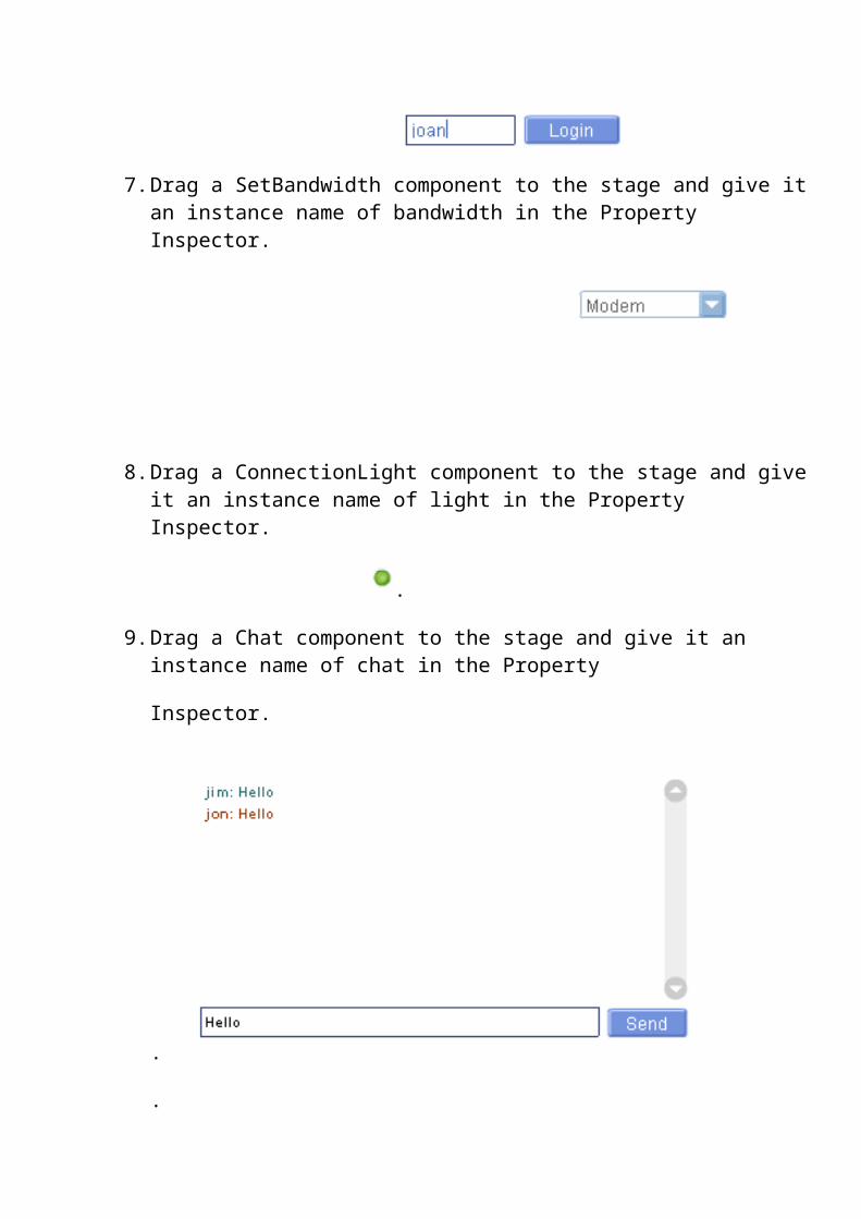
7. Drag a SetBandwidth component to the stage and give it an instance name of
bandwidth in the Property Inspector.

8. Drag a ConnectionLight component to the stage and give it an instance name of light in the Property Inspector.
.
9. Drag a Chat component to the stage and give it an instance name of chat in the Property
Inspector.
.
.
10.Drag a UseColor component to the stage and give it an instance name of colors in the Property Inspector.

11.Drag a VideoConference component to the stage and give it an instance name of vidchat in the Property Inspector.
12.Now is a good time to save your work.
13.Now click on the SimpleConnect component, and look at the Property Inspector.
14.Click on the Application Directory parameter and change rtmp:/app_default to rtmp:/firstapp.
15..Create the drawing board by creating a movie clip symbol, and drag it into the stage.
16. Drag a Button component to the stage and give it an instance name of draw_button_mc in the Property Inspector. click on the parameters and set the label as Draw and click handler as drawfun.
17. Drag a another Button component to the stage and give it an instance name of
erase _button_mc in the Property Inspector. click on the parameters and set the label as Erase and click handler as erasefun.
18. Create a movie clip of pen and give its instance name as SharedBall_mc in property inspector.
19. Create simple animation to decorate your screen.

20.Click on the Communication Components parameter and on the magnifying lens next to the Communication Components parameter. A Values pop-up window will appear as shown in this illustration.
Click on the plus sign 9 times until slots 0 through 8 are created. Click on the first slot where it says defaultValue, and type canvas_mc Tab to the second slot and type colors. Tab to the next slot and type chat Tab to the next slot and type light Tab to the next slot and type bandwidth Tab to the next slot and type vidchat Tab to the next slot and type draw_button_mc Tab to the next slot and type erase_button_mc Tab to the next slot and type SharedBall_mc
Your values window should now look like this:
Click OK and save your work.
All done !.

CODING / ACTIONS
Create layers in time line and copy these codes in frame one in Actions frame.If Actions frame is not visible then Goto Window Actions or click f9.
Global variable declaration
var e;var x;var strvar col;
Codes for pen
//Create a connectionclient_nc = new NetConnection();
// Show connection status in output windowclient_nc.onStatus = function(info) {
//trace("X " + X);};
// Connect to the applicationclient_nc.connect("rtmp:/messenger");
// Create a remote shared objectball_so = SharedObject.getRemote("position", client_nc.uri, false);this.createEmptyMovieClip("canvas_mc", this.getNextHighestDepth());// Update ball position when another participant moves the ballball_so.onSync = function(list) {

SharedBall_mc._x = ball_so.data.x;SharedBall_mc._y = ball_so.data.y;
//ball_so.onSync==canvas_mc;eraser._x = ball_so.data.x;eraser._y = ball_so.data.y;butt_enterSurvey.setEnabled(true);
};
// Connect to the shared objectball_so.connect(client_nc);
// Manipulate the penSharedBall_mc.onPress = function() {
canvas_mc.lineStyle(str,col, 100);
this.onMouseMove = function() {ball_so.data.x = this._x = _root._xmouse;ball_so.data.y = this._y = _root._ymouse;
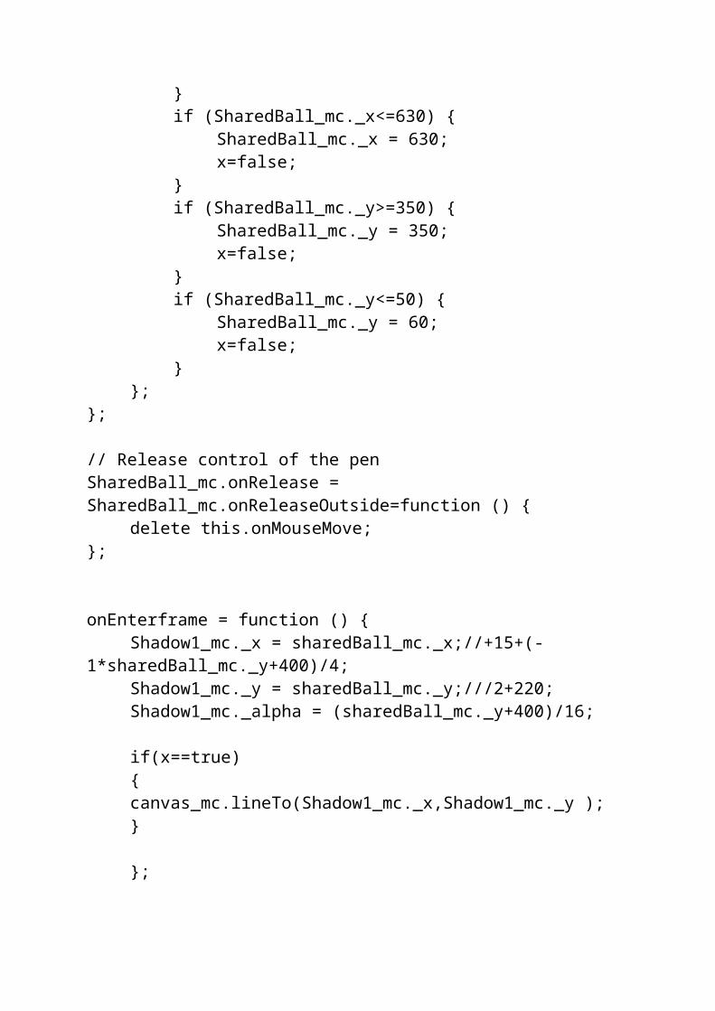
// Constrain the ball to the stageif (SharedBall_mc._x>=870) {
SharedBall_mc._x = 870;//Stage.width - 100;x=false;
}if (SharedBall_mc._x<=630) {
SharedBall_mc._x = 630;x=false;
}if (SharedBall_mc._y>=350) {
SharedBall_mc._y = 350;x=false;
}if (SharedBall_mc._y<=50) {
SharedBall_mc._y = 60;x=false;
}};
};

// Release control of the penSharedBall_mc.onRelease = SharedBall_mc.onReleaseOutside=function () {
delete this.onMouseMove;};
onEnterframe = function () {Shadow1_mc._x = sharedBall_mc._x;//+15+(-
1*sharedBall_mc._y+400)/4;Shadow1_mc._y = sharedBall_mc._y;///2+220;Shadow1_mc._alpha = (sharedBall_mc._y+400)/16;
if(x==true){canvas_mc.lineTo(Shadow1_mc._x,Shadow1_mc._y );}
};
Codes for Draw Button
function drawfun() {if(x==true){x=false;}
else {
x=true;str=2;col=0xFF0000;}
}
Codes for Erase Button
function erasefun() {if(e==true)

{
e=false;x=false;}
else {
e=true;x=true;str=7;col=0x006600;}
}
Codes for login component
/* ..This code is inbuilt and no need to write this code. Many more codes of the components are not written here you can see the codes in the program, they are already written. So, they can be used by simply importing the components… */
#initclip 1//function FCSimpleConnectClass() {
this.init();}//FCSimpleConnectClass.prototype = new MovieClip();//Object.registerClass("FCSimpleConnectSymbol", FCSimpleConnectClass);//FCSimpleConnectClass.prototype.onUnload = function() {
this.close();};// Initializes this Component, hides the Change Name Pop-up dialog// Creates a Key Listener for Keys pressed inside the User Name text boxFCSimpleConnectClass.prototype.init = function() {
//this.name = (this._name == null ? "_DEFAULT_" : this._name);this.prefix = "FCSimpleConnect." + this.name + ".";
this.enterListener = new Object();this.enterListener.owner = this;this.enterListener.enterPressed = false;
this.enterListener.onChanged = function () {if (this.owner.username_txt.text.length == 0) {
this.owner.changeName_btn.setEnabled(false);} else {
this.owner.changeName_btn.setEnabled(true);enterChar =
this.owner.username_txt.text.charAt(Selection.getEndIndex()-1);if (enterChar == String.fromCharCode(Key.ENTER) ) {
this.owner.username_txt.text = this.owner.username_txt.text.substring( 0 , this.owner.username_txt.text.length-1);
this.owner.loginChange();}
}};this.username_txt.addListener(this.enterListener);
};//FCSimpleConnectClass.prototype.close = function() {
// Let our server side counterpart know that we are going awaythis.nc.call(this.prefix + "close", null);//this.nc.FCSimpleConnect[this.name] = null;this.nc = null;
};//// Establishes a NetConnection using the appDirectory parameter,// User Name and appInstance if available// Handles basic NetConnection onStatus events// and Attaches other components specified in the FlashCom Components// parameter to the new NetConnectionFCSimpleConnectClass.prototype.serverConnect = function(username, appInstance) {
// Cleanup componentsthis.close();for (var i = 0; i < this.fcComponents.length; i++) {
this._parent[this.fcComponents[i]].close();}this.main_nc.close();
// Uses an app instance if it's passed as a parameter to the movieif (appInstance != null) {
this.appDirectory += "/" + appInstance;}// Check for last User Name, use username passed if suppliedif (username != null) {
this.username = username;this.changeName_btn._visible = false;this.inputBg_mc._visible = false;
} else {this.local_so = SharedObject.getLocal("FCUsername", "/");

if (this.local_so.data.username != null) {this.username = this.local_so.data.username;this.changeName_btn.setEnabled(true);
}}//if (this.appDirectory.substring(0,8).toUpperCase() ==
"FROMXML/") {//need to load the server name from settings.xml
this.attachMovie("SettingsXMLLoaderSymbol","appSettings",0);this.appSettings.load();this.appSettings.owner = this;this.appSettings.onLoadSettings = function() {
if (this.serverName != "null/")this.owner.appDirectory = "rtmp://" +
this.serverName + "" + this.owner.appDirectory.substring(8);else
this.owner.appDirectory = "rtmp:/" + this.owner.appDirectory.substring(8);
this.owner.actualConnect();}
} elsethis.actualConnect();
};//FCSimpleConnectClass.prototype.actualConnect = function(newName) {
this.rtmp_nc = new NetConnection();this.rtmp_nc.owner = this;this.rtmp_nc.onStatus = function(info) {
this.pending = false;
if (info.code == "NetConnection.Connect.Success") {if (this.owner.rtmpt_nc.pending) {
this.owner.rtmpt_nc.onStatus = null;this.owner.rtmpt_nc.close();this.owner.rtmpt_nc = null;
}this.owner.main_nc = this;this.owner.connect(this);
} elseif (!this.owner.rtmpt_nc.pending)
this.owner.raiseOnStatus(info);}
this.rtmpt_nc = new NetConnection();this.rtmpt_nc.owner = this;this.rtmpt_nc.onStatus = function(info) {
this.pending = false;

if (info.code == "NetConnection.Connect.Success") {if (this.owner.rtmp_nc.pending) {
this.owner.rtmp_nc.onStatus = null;this.owner.rtmp_nc.close();this.owner.rtmp_nc = null;
}this.owner.main_nc = this;this.owner.connect(this);
} elseif (!this.owner.rtmp_nc.pending)
this.owner.raiseOnStatus(info);}
this.rtmp_nc.pending = true;this.rtmpt_nc.pending = true;
//if rtmp is specified, try both rtmp and rtmpt //one after the other, and take the one that succeeds first.var i=this.appDirectory.indexOf(":");if (this.appDirectory.substring(0,i) == "rtmp") {
this.appDirectoryNoProtocol = this.removeSpaces(this.appDirectory).substr(i);
this.rtmp_nc.connect("rtmp"+this.appDirectoryNoProtocol, this.username);
this.conn_int = setInterval(this,"connectRtmpt",250);} else {
this.rtmp_nc.connect(this.removeSpaces(this.appDirectory), this.username);
}}
FCSimpleConnectClass.prototype.connectRtmpt = function() {clearInterval(this.conn_int);this.rtmpt_nc.connect("rtmpt"+this.appDirectoryNoProtocol,
this.username);}//FCSimpleConnectClass.prototype.connect = function(nc) {
//Connect
this.setUsername(this.username);
this.nc = nc;if (this.nc.FCSimpleConnect == null) {
this.nc.FCSimpleConnect = {};}this.nc.FCSimpleConnect[this.name] = this;
//// Need to call connect on our server side counterpart firstvar res = new Object();res.owner = this;

res.onResult = function(val) {this.owner.attachComponents();
}this.nc.call(this.prefix + "connect", res, this.username);
}
FCSimpleConnectClass.prototype.attachComponents = function() {//Attach Componentsfor (var i = 0; i < this.fcComponents.length; i++) {
this._parent[this.fcComponents[i]].connect(this.main_nc);
this._parent[this.fcComponents[i]].setUsername(this.username);}this.onComponentsConnected();
}
// Update the username for this componentFCSimpleConnectClass.prototype.setUsername = function(newName) {
if (newName == null) {this.username_txt.text = "Your Name";
} else {this.username = newName;this.username_txt.text = newName;
}};
// Callback from server when name is changedFCSimpleConnectClass.prototype.changedName = function(newName) {
for (var i = 0; i < this.fcComponents.length; i++) {this._parent[this.fcComponents[i]].setUsername(newName);
}};
// Sends a changeName call to the server to actually change this user's nameFCSimpleConnectClass.prototype.loginChange = function() {
// Only if the username has actually changed send it the serverif (this.username_txt.text.length == 0) {
this.changeName_btn.setEnabled(false);} else if (this.username != this.username_txt.text) {
this.username = this.username_txt.text;this.main_nc.call(this.prefix + "changeName", null,
this.username);this.local_so.data.username = this.username;this.local_so.flush();
}};
//FCSimpleConnectClass.prototype.checkName = function() {
clearInterval(this.intervalID);

var newName = this.username_txt.text;var btn = this.changeName_btn;if (newName.length == 0) {
btn.setEnabled(false);} else if (newName.charAt(0) == " ") {
btn.setEnabled(false);} else if (btn.enabled == false) {
btn.setEnabled(true);}
};
FCSimpleConnectClass.prototype.removeSpaces = function(str) {//remove leading spacesvar i=0;while (str.charAt(i) == " ") {
i++;}str = str.substr(i);//remove trailing spacesi = length(str)-1;while (str.charAt(i) == " ") {
i--;}str = str.substr(0,i+1);
return str;};
FCSimpleConnectClass.prototype.setSize = function(newWidth, newHeight) {
this._xscale = 100;this._yscale = 100;
this.username_txt._width = newWidth - 73;this.changeName_btn._x = newWidth -
this.changeName_btn._width;this.inputBg_mc._width = this.username_txt._width;
};
#endinitclip// // This is called from outside of initclip to make sure all// the other components have been inited, this establishes// a new NetConnection and connects any other FlashCom Componentsthis.setSize(this._width, this._height);this.serverConnect(_parent.username, _parent.appInstance);
NOTE :-

/*…………………………………………………………………………………… …The codes of the components are not written here you can see the codes in the program, they are already written. So, they can be used by simply importing the components… …………………………………………………………………………………..*/
TestingThe aim of the testing process is to identify all defects existing in a system. Systems are normally tested at the individual component (unit) level. This is called as testing in the small. After testing all the components individually, the components are slowly integrated and tested at each level of integration. Finally, fully integrated system is tested; this is called testing in large.Thus, a system goes through 3 levels of testing:
1. Unit Testing2. Integration Testing3. System Testing
1. Unit Testing:When individual components are tested and gives required
output is known as Unit testing.
2. Integration Testing:Integration testing is a process, where all modules are integrated
in a planned manner and tested accordingly.
3. System Testing:
System testing is used to check whether the system fulfill the users requirement or not. It is performed in 3 ways.
• α-testing :- It is performed by development team.
• β-testing :- It is performed by friendly user of customer.
• Acceptance testing : - It is performed by customer him self.
Publishing and testing application
Now that the application is built, we'll want to publish the files required to view it and test it to make sure everything is working as expected:
1. Within Macromedia Flash MX, select File -> Publish to create the HTML and SWF files that will be used to view the application in the browser. You can change the standard location of the files, e.g. if you wish to publish to a mounted webroot-directory at this point or publish your files to manually upload them to the webroot-directory.
2. In Windows, navigate to the folder you used for publishing the html and swf-files (e.g. flashcom\applications\firstapp\) and double-click on firstapp.html to open the application in your default browser. Or enter the URL of the webserver you uploaded your files to.
3. Enter a name in the SimpleConnect component text field and click "Login". 4. Type some text in the chat to make sure it gets displayed. 5. If you have a webcam installed, click on Send Audio/Video to broadcast your image and
audio (click Allow in the settings pop-up box). 6. To simulate multiple users connecting to the application, you can open another browser
window to the same page. 7. If you have a web server installed and the flashcom\applications\firstapp\ folder is
accessible from the server, invite a friend to join you in a video-conference by sending them the URL of your newly created application.
Debugging/Common mistakes
If the application doesn’t work correctly, it may be because the client was not able to connect to the Communication Server. The easiest way to determine if the client has a connection to the Flash Communication Server is to watch the connection light.
If this doesn't turn green or yellow, there is a problem with the connection, which can be caused by several things:
1. Make sure the file "main.asc" is in the right location: A common mistake is to place the file "main.asc" in the wrong folder. Remember: For security reasons in a deployment situation you have a webroot where your client files (.swf and .html) are stored and an application directory, where the file "main.asc" belongs in.
2. Verify the rmtp path in the Application Directory settings for the Simple_Connect component (from within the Macromedia Flash authoring environment) and make sure it is pointing to the right application. The location (machine) it is pointing to must be

running the Communication Server. E.g., if you're running Macromedia Flash Communication Server on your local machine, you should use rtmp:/firstapp or rtmp://localhost/firstapp.
3. Publish as "Flash 6": In order to use the communication components you need to go to "Publish Settings" and choose publish as "Flash 6."
4. Check if the Macromedia Flash Communication Server is running. Go to Start > Programs > Macromedia > Flash Communication Server MX and click on Start Server.
5. You may be behind a firewall that blocks port 1935. In case you are using Version 1.0 ask your administrator to enable port 1935. Macromedia Flash Communication Server MX 1.5 comes with a new feature called "HTTP tunneling". This makes it possible to use port 80 and the http-protocol for communicating with the server.
6. Make sure you have the latest Macromedia Flash Player 6 installed. 7. Under certain circumstances it may take a long time (OS X) to connect to the
Communication Server, when the client is behind a firewall and/or proxy. This fall back handling was improved in the newest version of the Flash Player. (please see Technote # 18537 for further description of the new HTTP tunneling and related updates to relevant component)
In case you are able to connect to the server (i.e. the Connection Light is green or yellow), but have problems using video communications, there is a possibility that the wrong video device is selected:
1. Click the right mouse key anywhere inside the flash page and select "settings". 2. Click on the last icon (showing a webcam). 3. Choose the appropriate video input device - your webcam for instance, in case it is not
already selected.
Conclusion
The best and prompt service is for most requirement for any customer and concerned organization. In such modern advanced business environment the computerization phenomenon is a high tech invention of human being which provides service to all limitations of the present time.

Developing this project is very fruitful and satisfying one by which i become able to touch and understand each and every part of the system and tried to include every possible criteria in this project..The project is coded in an easier and more structured manner, so that any possible modification can be done easily. The system is a user friendly one. The users can handle the system easily. The time taken to complete the entire project is 2 weeks and takes minimum usage of available resources. Less time was spent in the analysis and design phase in order to make the system. The system is successfully implementation after the testing phase and installed properly. Now the system is working well and satisfies the need of the user.
Since the essential factor is survival in future and computerization is a precautionary measure for that.. I hope the user can get all necessary benefits from my software to which this project has been Developed.
Bibliography
While developing this project i had made references to various books, documentation and internet, that create my path towards successfully completion of the project.

1. Documentation that came with the Macromedia Flash MX.
2. Documentation that came with the Macromedia Flash Communication Server MX.
3. Fundamental of Software Engineering by Rajiv Mall
4. http://www.macromedia.com

About the author
Laveen senapati, has been programming for more than two years , and just can't get enough. He gets excited about every aspect of computer science, from programming languages to graphic design, from the inner workings of compilers to new-media art. Born in the fertile grounds of jeypore , he fell in love with Macromedia products while doing program in it. A long-time ultimate player.
“The future is not the result of choices among alternatives. It is a place that is created; first, in mind, next in will, then in action.”
Visit me at :- http://laveens.hpage.com e-mail :- [email protected]