Embed Size (px)
Citation preview

PDHengineer.com Course № E-3019
How to Start and How to Start: AC/DC Motor Control
This document is the course text. You may review this material at your leisure before or after you purchase the course. If you have not already purchased the course, you may do so now by returning to the course overview page located at: http://www.pdhengineer.com/pages/E‐3019.htm (Please be sure to capitalize and use dash as shown above.) Once the course has been purchased, you can easily return to the course overview, course document and quiz from PDHengineer’s My Account menu. If you have any questions or concerns, remember you can contact us by using the Live Support Chat link located on any of our web pages, by email at [email protected] or by telephone toll‐free at 1‐877‐PDHengineer. Thank you for choosing PDHengineer.com.
© PDHengineer.com, a service mark of Decatur Professional Development, LLC. E‐3019 C1

How to Start and How to Stop: AC/DC Motor Control
Robert J. Scoff, PE Copyright © 2008
Copyright © 2008, Robert J. Scoff, PE 1

Table of Contents Section Page #
1. Introduction 4 2. AC Induction Motor Starters 4 3. International Electrotechnical Commission (IEC 11 4. Wye Detla Starters 11 5. Auto Transformer Reduced Voltage Starting 13 6. Wound Rotor Motor Starting 15 7. Synchronous Motor Control Schemes 17 8. Inverters or Variable Frequency Drives (VFD’s 20 9. Solid State Soft Starters 22 10. DC Motor Starters 23 11. Conclusions 27
Copyright © 2008, Robert J. Scoff, PE 2

List of Illustrations Title Page # Figure 2.1 Schematic Drawing Showing the Parts of a Starter 5 Figure 2.2 Start Stop Circuit 6 Figure 2.3 Typical Power Circuit for a Motor Control 7 Figure 2.4 Complete Motor Control Circuit 7 Figure 2.5 General Electric CR306 Starter Showing Various Parts 8 Figure 2.6 Power and Control Schematic of an Across the Line Reversing Starter 10 Figure 4.1 Schematic Drawing showing Wye-Delta Motor Starting Technique 11 Figure 4.2 A Way to See How the Voltage Is Reduced to 58% for Wye Delta Starting 12 Figure 4.3 Schematic of a Wye Delta Starter 12 Figure 4.4 Ladder Logic for a Wye Delta Starter 13 Figure 5.1 Schematic Drawing of an Autotransformer Reduced Voltage Starter 14 Figure 5.2 Typical Control Scheme for an Autotransformer Reduced Voltage Starter 15 Figure 6.1 Schematic of a Wound Rotor Motor Showing Speed Control Resistors and
Contactors 15 Figure 6.2 Power Circuit for a Wound Rotor Induction Motor 16 Figure 6.3 Typical Start Stop Circuit for a Wound Rotor Induction Motor 16 Figure 7.1 Schematic Diagram of How a Synchronous Motor Is Made 18 Figure 7.2 Starting Technique for a Three Phase Synchronous Motor 19 Figure 8.1 Diagram Showing VFD Controller Block Diagram 20 Figure 8.2 Control Scheme for Use When it is Desired to Bypass the Inverter 21 Figure 8.3 A Way to Control the Contactors in an Inverter Bypass Circuit 21 Figure 9.1 Schematic of Solid State Soft Start Motor Starter 23 Figure 10.1 Schematic of a DC Motor 24 Figure 10.2 Picture of How a DC Motor Is Constructed 24 Figure 10.3 Older Style DC Motor Controller 25 Figure 10.4 Schematic Layout of a Typical Small Single Phase DC Drive 26 Figure 10.5 Typical Three Phase DC Drive Layout 27
Copyright © 2008, Robert J. Scoff, PE 3

1. Introduction The industrial world uses electric motors to move solids, liquids, and gases. These electric motors could be alternating current or direct current. The motors range from fractional horsepower to thousands of horsepower. For the motors to be effective there has to be a way to turn them off and on. The whole purpose of this course is to show how motors are turned off and on, or controlled. Motors can also be speed controlled. Since this is a course about motor control, various ways to control the speed of motors will also be discussed. With that in mind, let’s look at starters for AC induction motors.
2. AC Induction Motor Starters When AC induction motors are started, there is a large current that flows as soon as the power is applied to the motor. It is typically 6 to 10 times the running current. This means that the device that turns power on to the motor has to be able to handle a lot of current. Just to give some idea of the magnitude of this current, the following information was copied from the 2005 National Electric Code. Full Load Current Three Phase AC Motors Horsepower Current at 460 volts, 3 phase ½ 1.1 ¾ 1.6 At 460 volts, the full load current rating is just a
little higher than the horsepower rating for 3 phase motors. Notice that a 10 horsepower motor has a current rating of 14 amps, and a 100 horsepower motor has a current rating of 124 amps.
1 2.1 1&1/2 3 2 3.4 3 4.8 5 7.6 7%1/2 11 10 14 15 21 20 27 25 34 30 40 40 52 50 65 60 77 75 96 100 124 125 156 150 180 200 240 250 302 300 361 350 414 400 477 450 515 500 590
Copyright © 2008, Robert J. Scoff, PE 4

Even for a relatively small 10 Horsepower motor, the running current is 14 amps. That would make the starting current somewhere between 84 and 140 amps. Clearly this requires a relatively heavy duty switch. And that is what a motor starter is, a heavy duty electro-mechanical switch. This heavy duty switch consists of 3 main parts. They are a coil that is energized to operate the second part, a three pole relay or contactor. The third part is an overload relay. The overload relay consists of a current measuring device and an auxiliary contact. Usually there are also some low current auxiliary contacts that operate at the same time as the main high current contacts. Figure 2.1 shows a schematic drawing of the main parts of a three phase motor starter.
M
L1
L2
L3
A1 A2
T1
T2
T3
M
M
M
OverloadHeaters
ThreeLeads toMotor
ThreeLeadsfrom
PowerSupply
MotorStarter Coil
AuxiliaryContacts, One
Normally Openand One
Normally Closed
AuxiliaryOverloadContact
M
M
Figure 2.1 Schematic Drawing Showing the Parts of a Starter The function of each of the parts is as follows:
1) Power is supplied to the M coil through the A1, A2 terminals. 2) All of the M contacts change state, the three main contacts close, and the two smaller auxiliary
contacts change. The Normally Open (NO) contact closes, and the Normally Closed (NC) contact opens.
3) If there is power at the L1, L2, L3 terminals the T1, T2, T3 terminals become energized through the main M contacts.
4) If there is a motor connected to the T terminals, current flows to the motor and causes it to develop torque and start turning.
5) The current will cause the Overload Heaters to get warm.
Copyright © 2008, Robert J. Scoff, PE 5

6) If too much current flows to the motor for too long of a time, the now hot overload heaters will cause the Overload Contact to open.
Figure 2.1 shows a schematic of a typical circuit that is used to start and stop a motor.
Figure 2.2 Start Stop Circuit Something to note here is that X1, X2 is a low voltage, low power circuit. The X1, X2 voltage can be 120 Volts AC, 24 Volts AC, or as a DC voltage of 12 or 24 Volts. The only function of the X1, X2 power supply is to supply a current to energize the M coil. In operation, if the start pushbutton is pushed, current flows through the M coil, causing the M contact to close. The closing of the M contact causes current to flow through the M coil continuously. This is often called a seal in contact. If the stop pushbutton is pushed, the current flow through the M coil is broken, and the M contact opens. Thus, when the Stop pushbutton is released, the M coil stays de-energized. Note that the OL contact is in series with the M coil. If the overload heaters get too hot and cause the OL contact to open, the M coil will lose power. The overload contact can be self resetting or non self resetting. If it is non self resetting, an operator has to reset the overload contact so that the motor can be restarted. The drawing of Figure 2.2 is called a ladder diagram. In control schemes there can be many lines of control logic. This drawing only shows one line to start and stop one motor. Complicated control schemes can have dozens or even hundreds of lines. The power circuit of a motor control circuit is used to connect a high power voltage source to a motor. The contacts are completely different from the low power auxiliary contact. They are usually made of silver because silver is a good conductor and relatively corrosion proof. Figure 2.3 shows the power circuit of a motor starter. One thing to notice here is that the control power X1, X2 comes directly off of the power to run the motor through a transformer. The main disconnect not only turns off the power to the motor, but also turns off the power to the control transformer. The control transformer is used to lower the control voltage to a safer level and to isolate the control voltage from the three phase power voltage. Also, notice that there are three main fuses for the current going to the motor. These are a special type of fuse called time delay or dual element fuses. They are designed to carry a large current for a short period of time. Then, they will trip if the rated current or higher is flowing for a longer period of time. Since induction motors have 6 to 10 times rated current at start up, this type of fuse is necessary on motor starting circuits.
Copyright © 2008, Robert J. Scoff, PE 6

Figure 2.3 Typical Power Circuit for a Motor Control When the Power Circuit and the Control Circuit are put together, the circuit of Figure 2.4 is the result. To review, the contacts that carry current to the motor are much bigger that the auxiliary contacts and the overload contacts. The overload contacts and heaters are one unit often called an Overload Relay. Notice also, that one end of the control voltage, X2, has been connected to ground.
Fuse
Fuse
Fuse
Motor
ThreePhasePower
MotorInformationSuch as HP,RPM, Full
LoadCurrent
M
M
M
OL
OL
OL
Disconnect
Fuse Fuse
Fuse
ControlTransformer
Control Voltage to LadderLogic CircuitX1 X2
M
OLStopStart
M Figure 2.4 Complete Motor Control Circuit
Copyright © 2008, Robert J. Scoff, PE 7

Figure 2.5 shows a typical National Electrical Manufacturers Association (NEMA) starter. This one happens to be a General Electric Style CR306.
Coil
Input Power Terminals
Power contacts are underneath the coil
A2
A1
Auxiliary Contact
Overload Heaters Overload
Contact
Connections to Motor
Figure 2.5 General Electric CR306 Starter Showing Various Parts There are many manufacturers of NEMA rated starters in the country. Among them are Westinghouse, Cutler Hammer, Allen Bradley, Square D, General Electric, Siemens, and ABB. They all have to meet rigorous performance standards. The physical size and cost of NEMA starters increases quite a bit as the size of the starter goes up
NEMA electrical motor starters refer to a standardized rating system for the electrical performance of the most common style of American-built motor starters. NEMA starters are rated by size: 00, 0, 1, 2, 3, 4, 5, 6 and 7. Typical list prices of NEMA starters are as shown below:
Size List Price 00 $272 These prices were taken from the Siemens website, reference given
below. They are only meant to show the relative cost of different size starters. There may be discounts available. Do note that the price approximates doubles for each size above a size 1. http://www2.sea.siemens.com/Products/Controls/Resources/Class+14+Non-Reversing+Starter+Configurator.htm
0 $332 1 $375 2 $651 3 $1030 4 $2305 5 $5573 6 $13199 7 $19547
Copyright © 2008, Robert J. Scoff, PE 8

Maximum electrical motor horsepower and continuous current rating for different size NEMA starters for three phase motors can be found in the table below:
Maximum Horsepower (hp)
Full Voltage Starting Part Winding Starting Wye Delta Starting NEMA Size
NEMA Continuous
Amp Rating (Amp) 200V 230V 460V
575V 200V 230V 460V 575V 200V 230V 460V
575V
00 9 1.5 1.5 2
0 18 3 3 5
1 27 7.5 7.5 10 10 10 15 10 10 15
2 45 10 15 25 20 25 40 20 25 40
3 90 25 30 50 40 50 75 40 50 75
4 135 40 50 100 75 75 150 60 75 150
5 270 75 100 200 150 150 350 150 150 300
6 540 150 200 400 300 600 300 350 700
7 810 300 600 450 900 500 500 1,000
http://www.engineeringtoolbox.com/nema-starters-d_918.html One thing that has to be done when applying NEMA starters is that the overload relays and heaters have to be sized to the motor horsepower. Notice that each starter size is good for a maximum horsepower. That means that a size 00 starter can be used for a fractional horsepower motor to a 2 horsepower motor at 480 volts. Look at the above chart for a size 00 starter at 480 volts. See that the maximum motor that it can control is 2 horsepower. The overload relays then have to have overload heaters sized to the motor size, or more specifically, the full load motor current. There are two types of thermal overload relays. They are bi-metal and eutectic melting alloy types. In the bi-metal type, a bi-metallic strip is heated by the current flowing to the motor. As it heats, it bends, and if it bends too far it causes the overload contact to open. The eutectic melting alloy type actually has two pieces of metal soldered together. The current flowing to the motor causes the two pieces of metal to heat up, and if it gets too hot the solder melts and causes the overload contact to open. For both types, the overload heaters are sized to the motor full load current. The National Electric Code (NEC) allows the
Copyright © 2008, Robert J. Scoff, PE 9

heaters to be oversized by 25%. The same is true for the motor protection fuses. The disconnecting switch and fuses can be replaced by a proper type and size of circuit breaker. Newer starters come with an electronic overload relay. These overload relays perform the same function as the older thermal overload relays. A small special purpose micro-processor inside the device measures the current and causes the overload contacts to change state if too much current flows for too long a time. They are priced about the same as the older thermal types of overload relays. Reversing starters are used when it is desired to have a three phase induction motor run in either direction. A schematic of a reversing starter is shown in Figure 2.6.
Figure 2.6 Power and Control Schematic of an Across the Line Reversing Starter Look at Figure 2.6 and see that if the F contacts are closed, L1 is connected to T1, L2 is connected to T2, and L3 is connected to T3. Then if the R contacts are closed, L1 is connected to T3, L2 is connected to T2, and L3 is connected to T1. The effect is to reverse the T1 and T3 Motor connections. If that is done, The motor will run in the opposite direction. The sequence of operations for an across the line full voltage reversing starter is as follows:
Copyright © 2008, Robert J. Scoff, PE 10

1. To go forward, press the forward pushbutton. 2. To go in reverse, push the reverse pushbutton. 3. To stop, push the stop pushbutton. 4. Notice that the forward and reverse contactors are interlocked so that the forward contactor cannot
pull in if the reverse contactor is pulled in and vice versa.
Another rating system for motor starters is the International Electrotechnical Commission (IEC). The IEC standards are somewhat different from NEMA standards.
3. International Electrotechnical Commission (IEC) The IEC is a non government, not for profit organization whose function is to develop standards for the world market. Low voltage motor control is covered by IEC Standard Numbers 60947-4-1 for electro-mechanical devices and 60947-4-2 for semi-conductor devices. As a general rule, NEMA starters are tougher than IEC starters of similar ratings. IEC starters are also somewhat less expensive. All IEC starters are labeled the same. The terminals on an IEC device from one manufacturer will have the same terminal numbers as a device from another manufacturer. This is a real advantage when it is necessary to replace a starter from one manufacturer with a starter from another manufacturer. In application and operation the IEC starters will function just like the NEMA starters. The drawings for IEC devices are very specific. The standards tell how each device should be represented. This course is not intended to cover IEC designations. There are many websites where the standards can be purchased.
4. Wye Detla Starters Starting larger motors requires some way to limit the initial large currents that flow when starting such motors. One way to do that is to connect the three phases of a motor in a wye connection for starting. This will limit the voltage across each winding, and hence the current, to 58% of the current if the windings were connected in a delta configuration. Figure 4.1 shows a schematic of the wye and delta connections of a motor that can be started by this method.
Figure 4.1 Schematic Drawing showing Wye-Delta Motor Starting Technique
The voltage across each winding for the Wye connection is one divided by the square root of 3 or 58% of the voltage across the Delta connected winding. We can get this directly from pretending the Wye is inside of a delta, as shown in Figure 4.2.
Copyright © 2008, Robert J. Scoff, PE 11

Figure 4.2 A Way to See How the Voltage Is Reduced to 58% for Wye Delta Starting
Not only is there a special motor, but there has to be a special starter for doing a Wye Delta start. The motor is different because all 6 leads are brought our so that connections can be made. If the motor were not being used as a reduced voltage start application, only three leads need to be brought out where connections can be made. This is true for both Wye and Delta wound motors. As a matter of fact, it is not really necessary to know if the motor is wound as a Wye or Delta motor, if reduced starting voltage is not being done. Reduced voltage starting is done when large motors are started, and/or large static loads need to be moved on starting. The starter for a Wye Delta start is different form a standard motor starter. Figure 4.3 shows a schematic of a Wye Delta starter.
Fuse
Fuse
Fuse
1
4
25
3
6
L1
L2
L3
OL
OL
OL
M1
M2
M1
M2
M1
M2
S1
S1S1
FuseFuse
FuseControl Transformer
Control Voltage to Ladder Logic
Three Motor Windings withSix Leads Connected to Wye
Delta Starter
Figure 4.3 Schematic of a Wye Delta Starter
Copyright © 2008, Robert J. Scoff, PE 12

Notice that there are 3 power contactors, M1, M2, and S1. Each of them has 3 power rated contacts. The ladder logic diagram of the control of a typical wye delta starter is shown in Figure 4.4.
M1
TD
S1
OLStop
StartX1 X2
M2
M1
M2
S1
TD
TD
Figure 4.4 Ladder Logic for a Wye Delta Starter The sequence of operations is as follows:
1. The Start Pushbutton is pushed. 2. M1 and S1 contactors close and TD coil is energized and TD starts timing. 3. This causes the motor to be connected in a Wye configuration and current flows through the motor
windings. Figure 4.1 shows the schematic of this connection, and the connection can also be traced out in Figure 4.3. The starting torque is about 33% of full load torque and the starting current is approximately 200% full load current.
4. After a time delay determined by TD, the S1 contactor drops out and the M2 contactor pulls in. If the time delay is set properly, the motor is up to speed, and the current is held to a reasonable value. Time Delay TD is a time delay to operate.
This starting technique is primarily used for motors of 50 horsepower and more. Because it uses three power contactors with three contacts each, it is much more expensive than an across the line starter. The main advantage is that it limits the starting current to 200% of running current instead of a more typical 600% starting current. In many plants with marginally adequate power supplies this technique can mean the difference between being able to start large motors and not being able to start them. The torque limiting (to 33%) also helps prevent damage to mechanical components.
5. Auto Transformer Reduced Voltage Starting Another way to get a reduced voltage and thus current on motor starting is with an autotransformer reduced voltage starter. A typical autotransformer reduced voltage starter uses two autotransformers and two power contactors. One of the power contactors has three contacts and the other one has five contacts. The autotransformers typically have three taps. They are at 50%, 65%, and 80% of full voltage. The following chart shows the typical percent torque and current that result when a reduced voltage autotransformer starter is applied.
Copyright © 2008, Robert J. Scoff, PE 13

% Voltage %Torque % Rated Current 50 45 300 65 76 390 80 115 480 http://literature.rockwellautomation.com/idc/groups/literature/documents/wp/150-wp001_-en-p.pdf A schematic of a autotransformer reduced voltage starter is shown in Figure 5.1. A real advantage of this technique is that it is possible to select the amount of current and torque reduction that you desire. Most of the time the units are shipped form the factory with the 65% tap chosen. Notice that the drawing shows five M1 power contacts and three M2 power contacts. Like most control circuits, there are various techniques that will work to make this starter work properly. This starter requires that the five contact contactor M1 close first, and then after a short time delay, contactor M1 will open and contactor M2 will close and stay closed as long as the motor is running. Figure 5.2 shows a scheme that will work.
Figure 5.1 Schematic Drawing of an Autotransformer Reduced Voltage Starter In this control scheme, when the start pushbutton is pushed, control relay CR pulls in and causes M1 to pull in through the normally closed M2 and TD contacts. Then, since the TD coil is activated, it starts timing and after its time delay, M1 drops out, and M2 pulls in. This causes the motor to go from reduced voltage to full voltage. Although not usually done, it is possible to make a control scheme where the autotransformer can go through two or three steps as the motor accelerates. This would add considerably
Copyright © 2008, Robert J. Scoff, PE 14

to the cost and complexity of the control scheme. The time delay (TD) is a time delay on operate. That means that the TD contacts will close a period of time after power is supplied to the coil.
Figure 5.2 Typical Control Scheme for an Autotransformer Reduced Voltage Starter
6. Wound Rotor Motor Starting There is a type of induction motor called a wound rotor induction motor. It is different from a standard induction motor in that the rotor windings are connected to slip rings. The slip rings are then connected to a resistor network that can be switched into and out of the rotor circuit. Figure 6.1 shows a schematic of a wound rotor three phase induction motor. Note that there is a primary and secondary winding. The primary circuit is directly connected to the three phase power through a conventional starter. The secondary, which is actually the part that turns, is connected to the resistor network.
Figure 6.1 Schematic of a Wound Rotor Motor Showing Speed Control Resistors and Contactors The control scheme for this kind of motor requires that first the three phase stator must be supplied with power by a standard motor starter. Then three 2 pole contactors (C1, C2, and C3) must be operated in sequence as the motor speeds up. Figure 6.2 shows the power circuit for a wound rotor induction motor.
Copyright © 2008, Robert J. Scoff, PE 15

Figure 6.2 Power Circuit for a Wound Rotor Induction Motor There are many different control schemes to operate a wound rotor motor starter. The first thing that must happen is that the M contactor must operate, just like in a standard induction motor across the line starter. Then the Contactors C1, C2, and C3 must operate in the sequence C1, C2, C3. Figure 6.3 shows a control scheme that will work.
Figure 6.3 Typical Start Stop Circuit for a Wound Rotor Induction Motor
Copyright © 2008, Robert J. Scoff, PE 16
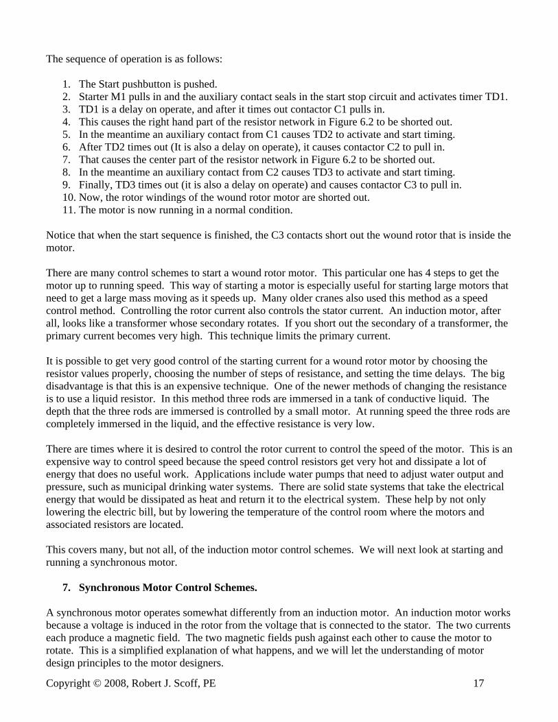
The sequence of operation is as follows:
1. The Start pushbutton is pushed. 2. Starter M1 pulls in and the auxiliary contact seals in the start stop circuit and activates timer TD1. 3. TD1 is a delay on operate, and after it times out contactor C1 pulls in. 4. This causes the right hand part of the resistor network in Figure 6.2 to be shorted out. 5. In the meantime an auxiliary contact from C1 causes TD2 to activate and start timing. 6. After TD2 times out (It is also a delay on operate), it causes contactor C2 to pull in. 7. That causes the center part of the resistor network in Figure 6.2 to be shorted out. 8. In the meantime an auxiliary contact from C2 causes TD3 to activate and start timing. 9. Finally, TD3 times out (it is also a delay on operate) and causes contactor C3 to pull in. 10. Now, the rotor windings of the wound rotor motor are shorted out. 11. The motor is now running in a normal condition.
Notice that when the start sequence is finished, the C3 contacts short out the wound rotor that is inside the motor. There are many control schemes to start a wound rotor motor. This particular one has 4 steps to get the motor up to running speed. This way of starting a motor is especially useful for starting large motors that need to get a large mass moving as it speeds up. Many older cranes also used this method as a speed control method. Controlling the rotor current also controls the stator current. An induction motor, after all, looks like a transformer whose secondary rotates. If you short out the secondary of a transformer, the primary current becomes very high. This technique limits the primary current. It is possible to get very good control of the starting current for a wound rotor motor by choosing the resistor values properly, choosing the number of steps of resistance, and setting the time delays. The big disadvantage is that this is an expensive technique. One of the newer methods of changing the resistance is to use a liquid resistor. In this method three rods are immersed in a tank of conductive liquid. The depth that the three rods are immersed is controlled by a small motor. At running speed the three rods are completely immersed in the liquid, and the effective resistance is very low. There are times where it is desired to control the rotor current to control the speed of the motor. This is an expensive way to control speed because the speed control resistors get very hot and dissipate a lot of energy that does no useful work. Applications include water pumps that need to adjust water output and pressure, such as municipal drinking water systems. There are solid state systems that take the electrical energy that would be dissipated as heat and return it to the electrical system. These help by not only lowering the electric bill, but by lowering the temperature of the control room where the motors and associated resistors are located. This covers many, but not all, of the induction motor control schemes. We will next look at starting and running a synchronous motor.
7. Synchronous Motor Control Schemes. A synchronous motor operates somewhat differently from an induction motor. An induction motor works because a voltage is induced in the rotor from the voltage that is connected to the stator. The two currents each produce a magnetic field. The two magnetic fields push against each other to cause the motor to rotate. This is a simplified explanation of what happens, and we will let the understanding of motor design principles to the motor designers.
Copyright © 2008, Robert J. Scoff, PE 17

For a synchronous motor, the stator is very much like an induction motor. However the rotating part, or rotor, is actually a DC electro magnet that catches the rotating magnetic field of the stator, and rotates with it. Hence it has the name, synchronous motor. It will rotate at a speed determined by the frequency of the incoming power supply. In the United States that is 60 cycles per second. Sixty cycles per second is 3600 cycles per minute, and 3600 revolutions per minutes is the fastest a synchronous motor can rotate. Other possible speeds include 3600 divided by any integer. So, 3600, 1800, 1200, 900, 720, 600, 514.28 revolutions per minute and so on are possible speeds. To get a synchronous motor to start some way has to be devised to get the motor up to speed before the rotating electromagnet is turned on. If the magnet were turned on before the synchronous speed was reached, the motor could shake itself apart as it first tried to go one way, and then the other. To imagine this, think of two permanent magnets that are brought close together. If a north pole were facing a south pole, and moved slightly off center, the magnets would want to move in one direction. If they were off center in the other direction, they would try to move in the other direction. This is no problem with two small magnets, but if one on the magnets is a rotating magnet that weighs several tons, real problems can occur. There are several methods to get the rotor of a synchronous motor up to speed before the rotating magnet is turned on. One is to actually mechanically couple a small motor to the rotor of the synchronous motor and get it up close to synchronous speed before turning on the DC rotating field. At best, this is kind of cumbersome. A better method is to actually build induction motor windings onto the rotor of the synchronous motor. Then, the motor could be started as an induction motor with some induction motor starting technique, and then switching on the DC rotating magnet when the motor got close to synchronous speed. With the right engineering, the rotating stator magnet would catch the now rotating DC magnet and the synchronous motor would run properly at the synchronous speed. Figure 7.1 shows a schematic of how a synchronous motor is made.
Figure 7.1 Schematic Diagram of How a Synchronous Motor Is Made
Let’s look at a technique for starting a synchronous motor. Figure 7.2 shows a workable starting method for Synchronous Motors.
Copyright © 2008, Robert J. Scoff, PE 18

Fuse
Fuse
Fuse
StatorWindings
Disconnect
ThreePhasePower
Fuse Fuse
Fuse
M
M
M
M
OL
OL
OL
OL
M
StartStop
VariableDC Power
Supply
M
TD
TDTD
M
Slip Ringand Brush
Slip Ringand Brush
RotorWinding
Note: Rotorwinding includesan inductionmotor winding toget motor up tospeed
Figure 7.2 Starting Technique for a Three Phase Synchronous Motor The way that this motor would start would be as follows:
1. The Start Pushbutton is pushed. 2. The M contactor pulls in and supplies power to the Stator windings. 3. At the same time the M contact in parallel with the start pushbutton seals in and keeps the M coil
energized. 4. The M contact feeding the Variable DC Power Supply closes and DC voltage is produced. 5. The M contact on the bottom line activates a On Delay Timer, TD. 6. After a pre set time delay the TD contacts supply power to the DC rotating magnet.
Copyright © 2008, Robert J. Scoff, PE 19
7. If all goes well the rotor catches the rotating magnetic field of the stator and the motor runs properly.
8. The variable voltage DC power supply is now adjusted to change the power factor of the motor to leading, lagging, or unity. The Power Factor of a synchronous motor can be changed by adjusting the strength of the rotating magnet. At one time this was a common method of keeping the power factor of industrial plants high.
There are other types of AC motors used for industrial purposes, but we have covered most applications. We will now look at another soft start technique, Inverters.
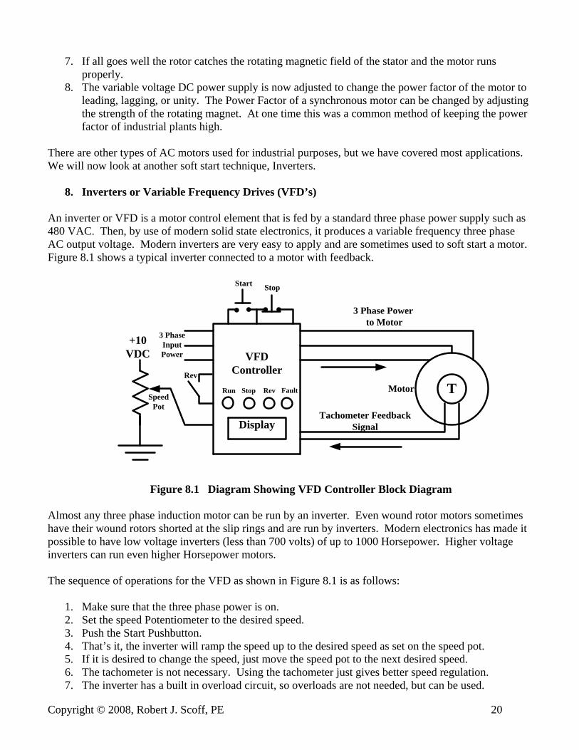
8. Inverters or Variable Frequency Drives (VFD’s) An inverter or VFD is a motor control element that is fed by a standard three phase power supply such as 480 VAC. Then, by use of modern solid state electronics, it produces a variable frequency three phase AC output voltage. Modern inverters are very easy to apply and are sometimes used to soft start a motor. Figure 8.1 shows a typical inverter connected to a motor with feedback.
+10VDC
T
3 Phase Power to Motor
Tachometer FeedbackSignal
Motor
VFDController
Display
Start Stop
Run Stop FaultRev
Rev
3 PhaseInputPower
SpeedPot
Figure 8.1 Diagram Showing VFD Controller Block Diagram Almost any three phase induction motor can be run by an inverter. Even wound rotor motors sometimes have their wound rotors shorted at the slip rings and are run by inverters. Modern electronics has made it possible to have low voltage inverters (less than 700 volts) of up to 1000 Horsepower. Higher voltage inverters can run even higher Horsepower motors. The sequence of operations for the VFD as shown in Figure 8.1 is as follows:
1. Make sure that the three phase power is on. 2. Set the speed Potentiometer to the desired speed. 3. Push the Start Pushbutton. 4. That’s it, the inverter will ramp the speed up to the desired speed as set on the speed pot. 5. If it is desired to change the speed, just move the speed pot to the next desired speed. 6. The tachometer is not necessary. Using the tachometer just gives better speed regulation. 7. The inverter has a built in overload circuit, so overloads are not needed, but can be used.
Copyright © 2008, Robert J. Scoff, PE 20

8. The display can be programmed to read one of several quantities including speed, current, and voltage.
Sometimes bypass contactors are used with VFD’s in case of VFD failure. Figure 8.2 shows a control scheme that will work in this case.
InverterMotor
ThreePhaseInput
Voltage
C1
C1
C1
C2
C2
C2
OL
OL
OL
C3
C3
C3
Figure 8.2 Control Scheme for Use When it is Desired to Bypass the Inverter It is never advisable to connect AC power to the output of an inverter. Depending on the price of a new inverter, it can be a very expensive mistake. C1 and C2 can be a 6 pole power contactor, if such a device is made. At the very least, C2 and C3 should be mechanically interlocked to make sure that both of them cannot be closed at the same time. Note that overload heaters have been added because the motor can run across the line. This particular overload relay would need 2 normally closed contacts, one to turn the inverter off and one to turn the C3 contactor off in case of an overload condition. The control scheme for this circuit is shown in Figure 8.3.
Figure 8.3 A Way to Control the Contactors in an Inverter Bypass Circuit
Copyright © 2008, Robert J. Scoff, PE 21

The operation of this circuit would be as follows:
1. If VFD is selected, start the inverter normally as shown in Figure 8.1. 2. If Bypass is selected, the motor will run. 3. If Off is selected, the motor will not run. 4. Notice that the contactors are electrically interlocked so that Bypass and Inverter cannot be turned
on at the same time. The use of inverters to run and control AC motors is becoming more and more common in the industrial world. The development of a transistor called an Insulated Gate Bipolar Transistor has enabled engineers to design reliable and affordable AC variable speed motor controllers. In many places where small DC motors and drives were formerly used, VFD’s and small induction motors have taken their place. One of the reasons is that an AC induction motor is a very reliable piece of equipment. It has only one moving part, the rotor. DC motors have brushes that require periodic changing. It seems that for the foreseeable future, Inverters are going to be more and more commonly used. Another solid state device used to start induction motors is a controller called a Soft Start.
9. Solid State Soft Starters Solid state soft starters are solid state devices that use 6 Silicon Controlled Rectifiers (SCR’s) to ramp up a motor’s voltage, current, and speed. They are not speed controllers. They only allow a motor to go from zero speed to full speed without a large current flow and they also minimize shock loads caused by starting a motor too quickly. With that in mind, let’s see how a soft start is made. Figure 9.1 shows how the power circuit of a Solid State Soft works. The sequence of operations is as follows:
1. Supply power to the circuit by closing the main disconnect. 2. Push the Start Pushbutton. 3. This seals in the control relay (CR), and supplies power to the control circuit. 4. The control circuit turns on the 6 SCR’s so that the voltage being supplied to the motor rises
slowly over time. 5. An adjustment called Acceleration time sets the time for the voltage going to the motor to go from
zero to full voltage of the incoming power supply. 6. The Current Transformer measures the current flowing to the motor. 7. The control circuit adjusts the turn on pulses going to the 6 SCR’s to keep the motor current from
going too high during the start up process. The maximum current allowed to flow is set by a Current Limit potentiometer.
8. The current limit may slow down the start up time to be longer than the time set by the Acceleration time potentiometer.
Solid State soft starts are used primarily when a motor has to start a large static load such as a large flywheel or a conveyor belt. They are also usually only used for motors of 50 horsepower or greater.
Copyright © 2008, Robert J. Scoff, PE 22

Fuse
1
23
45
6
Fuse
Fuse
Motor
OL
OL
OL
FuseFuse
Fuse
CR
CR
OL
Control Circuit
1 2 3 4 5 6
ControlTransformerStop Start
CurrentTransformer
ToControlCircuit
FromCurrent
Transformer
To Gates of the Six SCR’s
Figure 9.1 Schematic of Solid State Soft Start Motor Starter
10. DC Motor Starters To understand DC motor starting, we need to review DC motors, and how they are made. A DC motor is really two magnets, one that stands still, the stator and one that rotates, the rotor. The one that stands still is called the field, and the one that rotates is called the armature. The field (the part that stands still), can
Copyright © 2008, Robert J. Scoff, PE 23

be a permanent magnet or an electromagnet. Permanent magnets are usually only found on smaller motors of 2 horsepower or less. There are two kinds of electromagnetic fields, series and parallel. Let’s look at Figure 10.1 to see a schematic of a DC motor. Note that the electromagnetic fields can be replaced by a permanent magnet.
Series Field
ShuntField
VDC
Armature
Brush
Brush
Figure 10.1 Schematic of a DC Motor Before we talk about how this works, let’s talk about how it is constructed. Figure 10.2 shows the construction of a typical DC motor showing the fields and the armature, and a most important part, the communtator.
Figure 10.2 Picture of How a DC Motor Is Constructed Looking at Figure 10.1, notice that the shunt field and the series field both are used to make the stator magnet, shown in grey, stronger. The armature is shown with 4 coils. The brushes that the A1 A2 leads are connected to are stationary. Thus, when the armature turns, the coils that make the rotating magnet change. This is done by the communtator, shown in orange. The effect is that the two magnets always push against each other. Thus, the motor will turn and generate torque. Another thing to note is that the armature, as well as the series field, is a low resistance. That means that if the motor has a voltage across the armature a large current should flow. The current is actually limited as the motor speeds up, but at zero or low speed, the motor current is very large. Direct current also has the characteristic of not being easy to switch off for large motor loads. This makes the design of DC motor controls difficult. With that in mind, let’s look at several ways to control DC motors.
Copyright © 2008, Robert J. Scoff, PE 24

It should be possible to use a similar technique as used for AC motors to control DC motors. And it is. Figure 10.3 is a schematic of an older style DC motor controller made with contactors
Fuse
Fuse
Armature
Fuse Fuse
M
OL
M
StartStop
VDC
M
M
ShuntField
OL
Series Field
Disconnect
Figure 10.3 Older Style DC Motor Controller Notice that the shunt field is on as soon as the Disconnect is closed. This is to prevent a condition called Run-Away that occurs when a DC motor is operated without a field. Large motors have been known to literally tear themselves apart when they lose their fields. The voltage that runs the motor is also the control voltage. The series field is shown, but is not always used. The contactors are special design contactors that are able to handle both large turn on currents, and also the turn off transient currents that happen with DC motors. The contactors themselves are big, ugly, obsolete, and expensive. The only place where this kind of starting equipment is found is in older equipment that has not been modernized. Other than some smaller applications, most DC motors are controlled by solid state DC drives. The typical DC drive is fed by an AC voltage that is turned into a variable DC voltage by an electronic circuit consisting of SCR’s and a control circuit. Figure 10.4 shows a schematic of how a simple single phase DC drive is constructed. First, notice that there is no big contactor. Bigger DC drives have them, but they are not necessary on smaller motors. The armature voltage can be turned off by the control signals to the gates of the SCR’s. The gates need to be connected to the proper terminals on the control circuit, but this is done at the factory. Next notice that the field is fed by a bridge rectifier diode circuit that gives a full wave rectified current to the field. That current is present as soon as the disconnect is turned on. I emphasize again that the field current to a DC motor must never be turned off if there is a chance that the armature will have a DC voltage across it. Both the armature and the shunt field have a full wave solid state bridge feeding them, but the armature voltage is variable. For a 120 VAC supply, the field voltage is 100 VDC, and the armature voltage can vary from 0 to 90 VDC. For 240 VAC supply, the field voltage is 200 VDC and the armature can vary from 0 to 180 VDC.
Copyright © 2008, Robert J. Scoff, PE 25

Fuse
Fuse
1 2
3 4
Armature ShuntField
Control Circuit
1 2 3 4
VAC
Disconnect
+VDC
-VDC
+VField
-VField
Current Shunt Feedback Resistor
To ControlCircuit
Figure 10.4 Schematic Layout of a Typical Small Single Phase DC Drive The control circuit will have inputs that are connected to start stop controls and a speed setting potentiometer. Tachometer feedback is also possible to give better speed regulation. The control circuit will also have current limit and acceleration de-acceleration adjustments. Bigger motors need bigger equipment, and run on three phase instead of single phase. Figure 10.5 shows the layout of a typical three phase DC drive. For this drive, there is an emergency stop circuit consisting of an Emergency Stop Relay (ESR), a start pushbutton, and an emergency stop pushbutton. This is for safety purposes. An emergency stop circuit can have 2, 3, or more emergency stop pushbuttons in series so that an emergency stop can be initiated at more than one location. Pushing the Master Start (sometimes called Reset) pushbutton only allows the drive to run the motor. To actually run the motor the Motor Start pushbutton must be pushed, and then the control circuit causes the M contactor to pull in. Then, depending on the setting of the speed potentiometer, the motor will ramp up to speed. The acceleration time of the motor is set by an adjustment inside of the control circuit. There is also a current limit adjustment. The current is measured by the current shunt feedback resistor. The shunt field uses three diodes to generate a field voltage. Two of the diodes are used to rectify the incoming three phase voltage and one of them is called a flyback diode. Its function is to absorb the current that wants to keep flowing when the shunt field is turned off. Many DC drives incorporate a field loss relay. The function of the field loss relay is to shut down the drive when the field current drops below an acceptable level. The contact of the field loss relay is used to not allow the M contactor to pull in. One other thing that many larger DC drive systems have is a tachometer or encoder feedback. The tachometer is a small DC generator that attaches to the shaft of the motor and generates a voltage
Copyright © 2008, Robert J. Scoff, PE 26
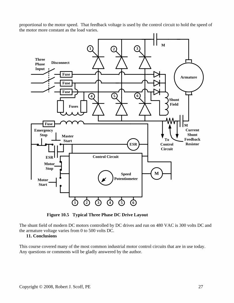
proportional to the motor speed. That feedback voltage is used by the control circuit to hold the speed of the motor more constant as the load varies.
Fuse
1 2 3
4 5 6
Fuse
FuseArmature
ThreePhaseInput
Disconnect
M
Fuse
Control Circuit
Fuses
ESR
1 2 3 4 5 6
ESR
MasterStart
EmergencyStop
SpeedPotentiometerMotor
Start
MotorStop
M
ShuntField
CurrentShunt
FeedbackResistor
M
ToControlCircuit
Figure 10.5 Typical Three Phase DC Drive Layout The shunt field of modern DC motors controlled by DC drives and run on 480 VAC is 300 volts DC and the armature voltage varies from 0 to 500 volts DC.
11. Conclusions This course covered many of the most common industrial motor control circuits that are in use today. Any questions or comments will be gladly answered by the author.
Copyright © 2008, Robert J. Scoff, PE 27