Embed Size (px)
Citation preview

FLOW METER
FM 1-CA
E-T-A ELEKTRO-TECHNISCHEAPPARATE GmbH
E 10.3B FM 1-CA E/c1090
USER HANDBOOK
D-90518 AltdorfTelephone: +49(09187)10-0Facsimile: +49(09187)10397www.e-t-a.com

Flow Meter FM 1-CA
Please follow these installation and adjustment instructions carefully.
Failure to comply with these instructions or misuse of this equipment will void your warrantycoverage.
The instructions cover software version 2.30.
Equipment installation, connection and adjustment by qualified personnel only!

Flow Meter FM 1-CA
Table of contents
1 Description ....................................................................................................................... 1
1.1 Measuring procedures ................................................................................................... 1
1.1.1 Calorimetric measuring procedure ..................................................................... 1
1.1.2 Physical principles in gas measurement ............................................................ 2
1.1.3 Standard and operating volume flow.................................................................. 2
1.1.4 Measurements in compressed-air systems ........................................................ 3
1.1.4.1 Consumption measurements ............................................................... 3
1.1.4.2 Leakage measurements ....................................................................... 3
1.2 System description ........................................................................................................ 4
1.2.1 User interfaces .................................................................................................... 5
2 Installation ........................................................................................................................ 7
2.1 Installation of calorimetric monitoring heads ............................................................... 7
2.1.1 Insertion head CSP for sensor adapter TP- ....................................................... 7
2.1.1.1 Sensor adapter TP- .............................................................................. 8
2.1.1.2 Mounting instructions(monitoring head CSP-.. with sensor adapter TP-) ............................. 8
2.1.1.3 Ball valve ............................................................................................... 9
2.1.2 Thread-mounted monitoring head CST (CST-11AM1) ..................................... 10
2.1.2.1 Mounting instructions ........................................................................ 11
2.1.2.2 Sealing ................................................................................................ 11
2.1.3 Push-in monitoring head (CSF-11AM1) ............................................................ 12
2.1.4 Mounting position .............................................................................................. 14
2.1.5 Condensate deposits ........................................................................................ 14
2.1.6 Electrical connection ......................................................................................... 14
2.2 Installation of electronic control unit FM 1-CA ........................................................... 15
2.2.1 Mechanical installation ...................................................................................... 15
2.2.1.1 Rail-mounted version ......................................................................... 15
2.2.1.2 Surface mounted version ................................................................... 15
2.2.2 Electrical connection ......................................................................................... 16
2.2.2.1 Circuit diagram FM 1-CA 24 V (open collector outputs) ................... 19
2.2.2.2 Circuit diagram FM 1-CA 24 V (relay outputs) .................................. 20
2.2.2.3 Electrical connection - frequency output (version FM 1-CA-U1T4) ... 21
Table of contents I
Flow Meter FM 1-CA
II Table of contents
3 Operation ........................................................................................................................ 23
3.1 Operating system ........................................................................................................ 23
Touch switches .................................................................................................. 23
Menu paging ...................................................................................................... 24
Calling a menu option ....................................................................................... 24
Entry of numerals .............................................................................................. 24
Transfer of entries .............................................................................................. 24
Deleting data ..................................................................................................... 24
3.1.1 Configuration ..................................................................................................... 25
3.1.1.1 Selection of monitoring head (SENSOR SELECT) ............................ 25
3.1.1.2 Pressure range (PRESS. RANGE) ...................................................... 26
3.1.1.3 Operating mode (OPERAT. MODE) .................................................... 26
3.1.1.4 Gas selection (GAS SELECT) ............................................................ 26
3.1.1.5 Limit switch combinations (LIMIT SWITCHES) ................................. 27
3.1.1.6 Flow rate unit (FLOW UNIT) ............................................................... 27
3.1.1.7 Medium temperature unit (TEMP. UNIT) ............................................ 27
3.1.1.8 Display (DISPLAY SELECT) ............................................................... 28
3.1.1.8.1 Bar graph (BARGRAPH) ..................................................... 28
3.1.1.8.2 Frequency output (FREQUENCY OUTPUT) ....................... 29
3.1.1.9 Analogue output - flow rate (ANA OUT FLOW) ................................. 30
3.1.1.10 Analogue output - medium temperature (ANA OUT TEMP.) ............. 30
3.1.1.11 Quitting the configuration menu ........................................................ 31
3.1.1.12 Configuration menu ........................................................................... 32
3.1.1.13 Configuration submenus .................................................................... 33
3.1.2 Parameter selection .......................................................................................... 36
3.1.2.1 Measuring time (MEAS. TIME) ........................................................... 36
3.1.2.2 Limit switch 1 ON/OFF value (LS1 ON / LS1 OFF) ........................... 36
3.1.2.3 Limit switch 2 ON/OFF value (LS2 ON / LS2 OFF) ........................... 37
3.1.2.4 Scaling factor (FLOWSCALE) ............................................................ 37
3.1.2.5 Quitting the parameter selection menu ............................................. 37
3.1.2.6 Parameter selection menu ................................................................. 39
3.2 Low flow suppression .................................................................................................. 40
3.2.1 Low flow suppression ....................................................................................... 40
3.2.2 Zero adjustment ................................................................................................ 40
Flow Meter FM 1-CA
Table of contents III
4 On-line phases .............................................................................................................. 41
4.1 Switch-on performance ............................................................................................... 41
4.2 Measuring cycle ........................................................................................................... 41
4.2.1 Operating data ................................................................................................... 41
4.2.1.1 Measured value(s) .............................................................................. 41
4.2.1.2 Peak values (PEAK VALUE MIN / PEAK VALUE MAX) ...................... 43
4.2.1.3 Low flow suppression (ZERO SUPP.) ............................................... 43
4.2.1.4 Last error (LAST ERROR) ................................................................... 43
4.2.1.5 Main menu .......................................................................................... 44
5 Errors ................................................................................................................................ 45
5.1 Test and diagnosis ....................................................................................................... 45
5.1.1 Priority group I ................................................................................................... 45
5.1.2 Priority group II .................................................................................................. 45
5.1.3 Priority group III ................................................................................................. 45
5.2 Potential errors ............................................................................................................ 46
6 Directions for calorimetric monitoring heads ..................................................... 48
6.1 Selection of material .................................................................................................... 48
6.1.1 Stainless steel 1.4571/AISI 316 Ti .................................................................... 48
6.1.2 Nickel-based alloy (Hastelloy 2.4610) ............................................................. 48
7 Technical data ............................................................................................................... 49
7.1 Ambient conditions ...................................................................................................... 49
7.2 Electrical characteristics ............................................................................................. 49
7.2.1 Power supply ..................................................................................................... 49
7.2.1.1 DC voltage supply .............................................................................. 49
7.2.1.2 AC voltage supply .............................................................................. 50
7.3 Analogue outputs ........................................................................................................ 50
7.3.1 Voltage output V1 - 5 V FS ................................................................................ 51
7.3.2 Voltage output V2 - 10 V FS .............................................................................. 51
7.3.3 Current output C1 - 20 mA FS (self-powered) ................................................. 51
7.4 Signal outputs .............................................................................................................. 52
7.4.1 Relay outputs .................................................................................................... 52
7.4.2 Open collector outputs (DC switching voltage) ................................................ 53

Flow Meter FM 1-CA
7.5 Metrological data ......................................................................................................... 54
7.5.1 Mass flow measurement ................................................................................... 54
7.5.1.1 Monitoring head CSP-.. with sensor adapter TP- ................................ 54
7.5.1.2 Monitoring heads CST- and CSF- ..................................................... 54
7.5.2 Temperature measurement ............................................................................... 55
7.5.3 Electronic control unit FM 1-CA........................................................................ 56
7.6 Sensor interface ........................................................................................................... 57
7.6.1 Electrical data of the terminal for calorimetric monitoring heads .................... 57
Index
Appendix
1 Performance of the digital and analogue outputs during operating and error modes
2 Menu structure of the FM 1-CA (operator dialogue)
IV Table of contents
Flow Meter FM 1-CA
1 Description
1.1 Measuring procedures
Flow Meter FM 1-CA is suitable for compressed-air and other gas flow measurements undervarious pressure conditions. It operates on the calorimetric principle and is to be used togetherwith monitoring heads CS_..
1.1.1 Calorimetric measuring procedure
The calorimetric measuring procedure is based on the physics of heat dissipation, i.e. a bodywith a temperature higher than its surroundings supplies a medium flowing past that body withenergy in the form of heat. The amount of energy supplied is a function of temperature difference∆ϑ and mass flow.
Flow Meter FM 1-CA operates on the CTD (Constant Temperature Differential) method:
The temperature difference ∆ϑ between the two sensors is kept constant and the mass flow isdetermined by measuring the calorific power.
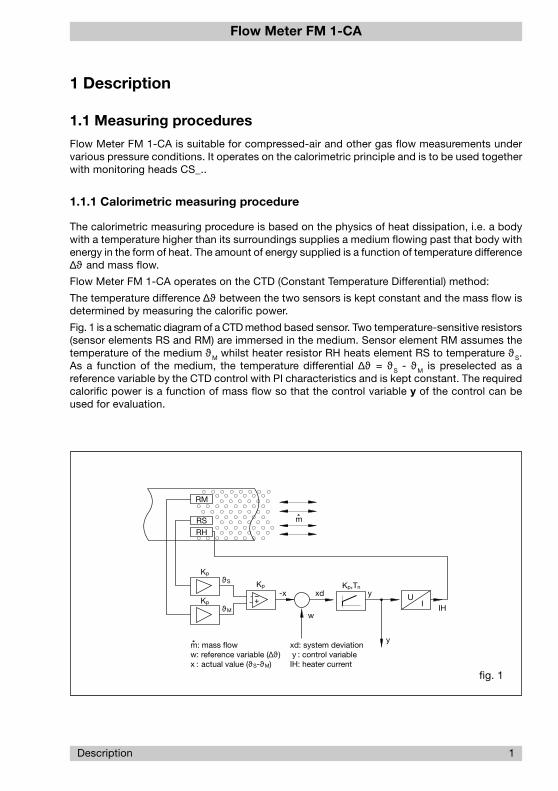
Fig. 1 is a schematic diagram of a CTD method based sensor. Two temperature-sensitive resistors(sensor elements RS and RM) are immersed in the medium. Sensor element RM assumes thetemperature of the medium ϑM whilst heater resistor RH heats element RS to temperature ϑS.As a function of the medium, the temperature differential ∆ϑ = ϑS - ϑM is preselected as areference variable by the CTD control with PI characteristics and is kept constant. The requiredcalorific power is a function of mass flow so that the control variable y of the control can beused for evaluation.
Description 1
fig. 1
RM
RS
RH
m
Kp
Kp
ϑS
ϑM
Kp
−+-x xd
w
yKp,Tn
UI IH
ym: mass floww: reference variable (∆ϑ )x : actual value (ϑS-ϑM)
xd: system deviation y : control variableIH: heater current

Flow Meter FM 1-CA
2 Description
P x VT
= constant
Major benefits of this method are:
Fast response, particularly to sudden flow standstill.
Medium temperature measurement, providing optimum temperature compensation.
Increased safety because the sensor cannot be overheated during flow standstill.
The flow rate is determined by mass flow.
1.1.2 Physical principles of gas measurement
With the exception of Coriolis meters and calorimetric flow meters, flow meters used for gasmeasurement are pure volume flow meters that require density ρ to determine mass flow Qfrom the volume flow measured:
Q = V x ρCoriolis meters are used for higher mass flow quantities and higher densities only, where den-sity is directly proportional to pressure and inversely proportional to temperature (related toabsolute Kelvin scale).
The quantity required in general practice is mass flow as it indicates the exact gas quantity,whereas volume flow only defines the volume the gas has adopted during the measurementprocedure.
1.1.3 Standard and operating volume flow
Standard volume flow
The calorimetric measuring procedure measures the existing standard volume flow or massflow without requiring additional pressure and/or temperature measurements. Like velocitychanges, pressure fluctuations cause fluctuations in standard volume flow which are indicatedas such. The standard volume flow indicated relates to 1,013 mbar/ 14.89 PSI and a tempera-ture of 0 °C.
Operating volume flow
The standard volume flow value is converted into operating volume flow by means of the “idealgas equation”:
with P being pressure, V the volume and T the temperature (related to the absolute Kelvinscale). The pressure to be set on the electronic control unit FM 1-CA and the current tempera-ture measured are taken into account and used as a basis. Calculating operating volume flowis only reasonable when pressure is known and constant.
The assigned velocity rates (averaged on the pipe section) are converted from standard condi-tions to operating conditions the same way as volume flow.

Flow Meter FM 1-CA
Description 3
1.1.4 Measurements in compressed-air systems
The easy-to-fit modular insertion system allows the FM 1-CA with insertion head CSP-.. to beinserted in 6 different sensor adapters for diameters 1/2", 3/4", 1", 1 1/4", 1 1/2" and 2". Thisenables to systematically monitor the entire compressed-air system for leakages by providingthe appropriate number of sensor adapters and only a few measuring systems. After elimina-tion of the leakages the measuring system can be used for consumption measurements onother measuring locations, e.g. before main loads or in larger pipes of the compressed-airsystem. The measuring range covering approx. 0 ... 50 Nm3/h to approx. 0 ... 480 Nm3/h allows themeasurement of nearly all common flow rates as a function of pipe diameter. Measurements inlarger pipe diameters are possible by using the thread-mounted monitoring head CST-11AM1.
1.1.4.1 Consumption measurements
The FM 1-CA with CS_- monitoring head is suitable for compressed air and other gases. Itselectronic control unit comprises two freely scalable linearised analogue outputs, i.e. one fortemperature, the other for mass flow, standard flow or operating volume flow. A pulse outputand totalizer for consumption measurements are other added features. It also provides limitvalue monitoring of flow and temperature, ensuring reliable operation of the load.
1.1.4.2 Leakage measurements
When monitoring compressed-air flow at some selected points during a production-free pe-riod, you will realise that even in carefully maintained compressed-air systems there is stillcompressed air consumed. Reliably detecting even the smallest of such leakage losses canbe facilitated by means of the adjustable zero suppression of the FM 1-CA. If the system ispermanently monitored for leakage flow, leakages caused by valves left open etc. and newleakage points can easily be detected.
The FM 1-CA also allows the detection of leakages on duty by comparing two equal loads witheach other. The difference measured can be directly assigned to the leakage flow.
Please observe the accuracy specified for the FM 1-CA and the appropriate CS.- monitoringhead.
Flow Meter FM 1-CA
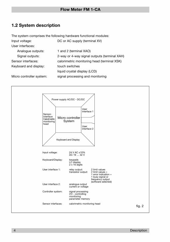
1.2 System description
The system comprises the following hardware functional modules:
Input voltage: DC or AC supply (terminal XV)
User interfaces:
Analogue outputs: 1 and 2 (terminal XAO)
Signal outputs: 2-way or 4-way signal outputs (terminal XAH)
Sensor interfaces: calorimetric monitoring head (terminal XSK)
Keyboard and display: touch switches
liquid crystal display (LCD)
Micro controller system: signal processing and monitoring
4 Description
fig. 2
Userinterface 2
Sensor-interfaceCalorimetricmonitoringhead
Power supply AC/DC - DC/DC
Keyboard and Display
Micro controllerSystem
Userinterface 1
24 V AC ±10%DC 19 … 32 V
keypadsLC display2 x 16 digits
relay output: 2 limit valuestransistor output: 2 limit values +
1 error indication +1 busy signal or frequency output(software selected)
analogue outputcurrent or voltage
signal processingI/O - controllingmonitoringparameter memory
calorimetric monitoring head
Input voltage:
Keyboard/Display:
User interface 1:
User interface 2:
Controller system:
Sensor interfaces:

Flow Meter FM 1-CA
Description 5
The power supply is physically isolated between power supply input and system powersupply output. This also applies to the analogue outputs which are physically isolated fromeach other as well as from the other electronics and the signal outputs. The signal outputchannels are also separate and electrically isolated from the central electronic unit.
There is no electrical isolation between monitoring head and central electronic unit.
The dielectric strength of the monitoring heads is specified in our CPI catalogue.
The dielectric strength between the individual sub-assemblies is specified in para. 7.6, Sensorinterfaces.
Connection of the monitoring heads is by means of precut cable links. Cables and user interfaceconnections are shown in para. 2.2 and circuit diagram 2.2.2.1/2.2.2.2.
System configuration and parameter setting are by means of the keyboard if default valuesneed to be changed (paras. 3.1.1 and 3.1.2).
This mainly applies to monitoring head selection, signal outputs (switch point setting) and analogueoutputs (zero point setting and scaling).
1.2.1 User interfaces
Signal outputs: 1. R2 - Relay outputs (2 limit values)(optional) Two-channel physical isolation, relay change over contact
The channels may be assigned, either individually or in pairs, to thephysical quantities of temperature or flow. The switch on and off valuescan be set as desired (yet within the measuring range) for each contact.
Please see para. 7.4.1 for electrical connection.
2. T4 - Transistor outputs (2 setpoints + 2 status outputs or1 status output + 1 frequency output)
Four-channel physical isolation, transistor output - collector/emitter freelyconnectable
Channel 1: common error signal
Channel 2: busy signal or frequency output
Channels 3 and 4: Both channels may be assigned individually or inpairs to the physical quantities of temperature or flow. The switch on oroff values of each transistor output can be set as desired.
Please see para. 7.4.2 for electrical connection.
Analogue outputs: Two-channel physical isolation, current or voltage output
Please see the ordering number to find out whether it is a current orvoltage output.
Output quantities: 0/1 - 5 V FS (full scale) (V1)0/2 - 10 V FS (V2)0/4 - 20 mA FS (C1 self-powered)
These FS output quantities apply to both channels as standard.

Flow Meter FM 1-CA
6 Description
20% zero elevation and FS value can be programmed. (See para. 3.1.1.10)
Shield connections are ungrounded.
The shields of the signal cables should be applied on one side only.
Power supply: DC or AC supply with physical isolation of the primary and secondaryside.
Power supply is by means of an isolating transformer. One of thesecondary voltages is regulated as actual value. The manipulatedvariable is fed, physically isolated, to the pulse duration modulator.
Noise emission on the connection cable is limited by circuit designand filter.
A PTC resistor provides protection from overcurrent. The element auto-matically resets upon removal of the disturbance.
Please see para. 7.2.1 for technical characteristics.

Flow Meter FM 1-CA
Installation 7
2 Installation
2.1 Installation of calorimetric monitoring heads
2.1.1 Insertion head CSP for sensor adapter TP-..
Application: general industry and installation
Style: insertion-type for sensor adapter TP and ball valve
Material of the area exposed to medium:
stainless steel 1.4571/AISI 316 Ti electro-polished
O ring viton
Installation: sensor adapter TP-.. (fig. 4)
ball valve (fig. 5)
ø20
ø18
18.2
14
64
8
ø24
retention slot
O ring
monitoring head CSP-11..
O ring retention pin
union nut
sensor adapter TP-…
fig. 3
Flow Meter FM 1-CA
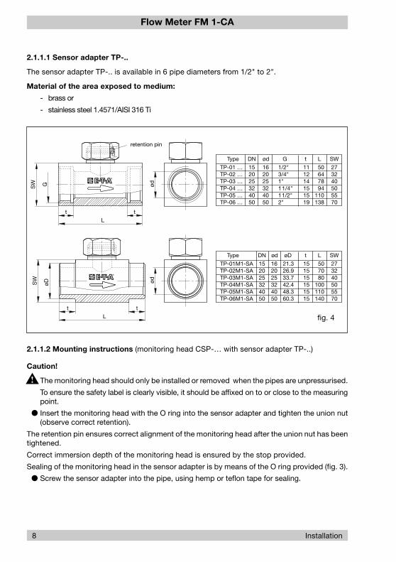
2.1.1.2 Mounting instructions (monitoring head CSP-… with sensor adapter TP-..)
Caution!
The monitoring head should only be installed or removed when the pipes are unpressurised.
To ensure the safety label is clearly visible, it should be affixed on to or close to the measuringpoint.
Insert the monitoring head with the O ring into the sensor adapter and tighten the union nut(observe correct retention).
The retention pin ensures correct alignment of the monitoring head after the union nut has beentightened.
Correct immersion depth of the monitoring head is ensured by the stop provided.
Sealing of the monitoring head in the sensor adapter is by means of the O ring provided (fig. 3).
Screw the sensor adapter into the pipe, using hemp or teflon tape for sealing.
2.1.1.1 Sensor adapter TP-..
The sensor adapter TP-.. is available in 6 pipe diameters from 1/2" to 2".
Material of the area exposed to medium:
- brass or
- stainless steel 1.4571/AISI 316 Ti
G
t
L
t
SW ød
ød
273240505570
SW
50647894
110138
111214151519
tød
162025324050
DNType
TP-01 …TP-02 …TP-03 …TP-04 …TP-05 …TP-06 …
152025324050
G
1/2"3/4"1"11/4"11/2"2"
L
tt
L
SW
øD
DN
152025324050
273240505570
SW
507080
100110140
151515151515
tød
162025324050
Type
TP-01M1-SATP-02M1-SATP-03M1-SATP-04M1-SATP-05M1-SATP-06M1-SA
LøD
21.326.933.742.448.360.3
retention pin
8 Installation
fig. 4

Flow Meter FM 1-CA
Installation 9
fig. 5
41505470
SW
88100110131
21242428
tød
25324050
DNType
BV-03M3BV-04M3BV-05M3BV-06M3
25324050
G
1"11/4"11/2"2"
L
59657785
H
115115150150
A
H
ød G
t
SW
A
L
2.1.1.3 Ball valve
The ball valve of Postberg GmbH at D-63485 Bruchköbel is available in 4 nominal diametersfrom 1" to 2". The ball valve ensures the sensors are fully immersed in the medium.
The monitoring head may also be replaced in pressurised pipe systems on duty.
Note:
Please see the applicable drawing of Postberg GmbH for mounting instructions anddimensions, if necessary.

Flow Meter FM 1-CA
2.1.2 CST - Thread mounted monitoring head CST-11AM1
Application: general industry and installationrecommended for inner pipe dia. 25 mm … 100 mm
Style: G1/2A
Material of the area exposed to medium:
stainless steel 1.4571/AISI 316 Ti
nickel-based alloy (Hastelloy 2.4610)
10 Installation
fig. 6
G1/2A
14
10
36
ø18
SW27
14
round connector
fixing shank
screw-in bushing
+10°
-10°
wrench flats (S)
M

Flow Meter FM 1-CA
Installation 11
2.1.2.1 Mounting instructions
The two sensors (M) should be screwed into the pipeline far enough to ensure that they arealigned side by side directly across the direction of flow. The sensors are correctly positionedwhen the wrench flats (S) are aligned parallel with the pipeline. The angular displacement mustnot exceed ±10°.It is recommended to install the monitoring head in a screw-in bushing welded on to the pipe.
Caution!
The surface of the shank end should be flush with the inner pipe wall (see fig. 3). Ensure thesensors are positioned fully in the flow stream.
The surface of the shaft end must not be recessed below the inner pipe wall. Preferablythe shaft surface of the CST monitoring head should project approx. 1-2 mm towardsthe pipe centre.
For inner pipe diameters of 60 mm plus please use the installation instructions of the CSFmonitoring head (fig. 7) for the CST monitoring head.
To ensure the Flow Meter is correctly installed
affix the screw-in bushing with the monitoring head and the sealing to the pipe
fully weld in the bushing (without monitoring head and sealing)
and finally chase the thread.
2.1.2.2 Sealing
All thread-mounted monitoring heads have a metal sealing edge to DIN 3852, form B, to ensurefull sealing when the union has been completely screwed in.
DIN 3852 specifies how the screw holes for the union should be made.
Other sealing methods are metal or elastomere sealing rings, or sealing in the thread, e.g. bymeans of a teflon tape.
Flow Meter FM 1-CA
12 Installation
fig. 7
M
threaded installation bush0Z122Z000196
alignment of the monitoring head(arrow in direction of flow)
174
ø18
14
190
SW20
round connector
x
x → 1/8 of the inner pipe diameter
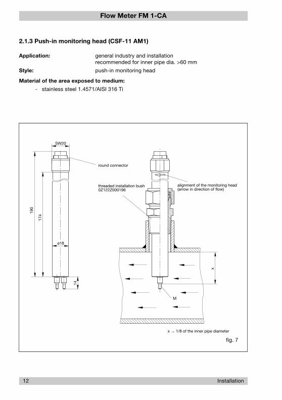
2.1.3 Push-in monitoring head (CSF-11 AM1)
Application: general industry and installationrecommended for inner pipe dia. >60 mm
Style: push-in monitoring head
Material of the area exposed to medium:
- stainless steel 1.4571/AISI 316 Ti

Flow Meter FM 1-CA
Standard velocity profiles:
(for pipe radius =1 and for velocity averaged via total pipe cross section = 1)
Installation 13
r
1.4
1.2
1
0.8
0.6
0.4
0.2
-1 -0.75 -0.5 -0.25 0 0.25 0.5 0.75 10
v
r
1.03
1.02
1.01
1
0.99
0.98
v
-0.77 -0.76 -0.75 -0.74 -0.73 -0.72
Velocity range at X = 1/8 dia. (see fig. 7)
fig. 8
Max. accuracy is achieved with an insertion depth of x = 1/8 inner pipe dia. (fig. 7).
r - pipe radius
v - velocity

Flow Meter FM 1-CA
2.1.4 Mounting position
The mounting attitude is unimportant. It is generally sufficient to have a distance of 10 pipediameters (D) before the monitoring head if the velocity profile is only slightly disturbed. Formuch disturbed velocity profiles, above all for a superimposed swirl-flow, there should be adistance of 20 to 50 pipe diameters (D) before the monitoring head in order to eliminate highdeviations in the values measured.
It is generally recommended to observe the following distances:
distance before the monitoring head: 15 … 20 x D
distance after the monitoring head: 5 x D
2.1.5 Condensate deposits
Oil or water condensates on the sensors may falsify the measuring results. Such deposits mustbe expected, for example, when high flow velocities of compressed air are concerned and thereis no drying provided. Normal condensation on an unheated sensor is normally not realised, it willdry up after a few minutes. Deposits on heated sensors only occur at high air humidities and willcause significant measuring errors. In most cases, such deposits will dry up within a few minutes.Deposits of oil, however, will not dry up and should be removed at regular intervals.
2.1.6 Electrical connection
14 Installation
fig. 9
R(HEIZ)
R(Tdiff)
cableKabel-UnionLifYCY 4 x 2 x 0.2 mm2
or equivalent cable
green2
green 7 7
yellow1
yellow 33
red6
red 4 4
blue5
pink
55
pink10
blue
8 8
grey9
grey 11
brown3
brown 6 6
white4
white 22
blackshield7/8
R(HEIZ)
R(Tref)
XSKFM1-CA
round plugX221 368 01
plug, flangeX221 369 01monitoring head

Flow Meter FM 1-CA
Installation 15
2.2 Installation of electronic control unit FM 1-CA
2.2.1 Mechanical installation
2.2.1.1 Rail-mounted version (fig. 10)
The electronic housing is mounted on a symmetric rail to EN 50022.
Removal is by releasing the spring catch.
For thermal reasons, the modules should be spaced by at least 10 mm.
The housing is able to withstand continuous temperatures up to 100 °C.
Storage temperature -20 … +70 °C.
Environmental protection: housing IP40, terminals IP20.
fig. 10
100
75
56
60
spring catch
2.2.1.2 Surface mounted housing (fig. 11)
Install the housing in place using the 4 M4 screws provided.
Storage temperature -20 … +70 °C Environmental protection IP64.

Flow Meter FM 1-CA
XAS - not released for user
XAO - analogue outputs
XAH - signal outputs
16 Installation
2.2.2 Electrical connection
fig. 12
fig. 11
103
138
71
PG9
PG11
138
125
ø4.5
mounting holes
1 2 3 1 2 3 4
XV XSK XTF
XAS XAO XAH
1 2 3 4 5 6 7 8 9 101 2 3
87654321 87654321 87654321
M
XV - power supply
XSK - calorimetric monitoring head
XTF - keyboard release
Flow Meter FM 1-CA
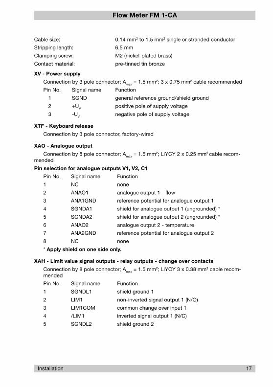
Cable size: 0.14 mm2 to 1.5 mm2 single or stranded conductor
Stripping length: 6.5 mm
Clamping screw: M2 (nickel-plated brass)
Contact material: pre-tinned tin bronze
XV - Power supply
Connection by 3 pole connector; Amax = 1.5 mm2; 3 x 0.75 mm2 cable recommended
Pin No. Signal name Function
1 SGND general reference ground/shield ground
2 +UV positive pole of supply voltage
3 -UV negative pole of supply voltage
XTF - Keyboard release
Connection by 3 pole connector, factory-wired
XAO - Analogue output
Connection by 8 pole connector; Amax = 1.5 mm2; LiYCY 2 x 0.25 mm2 cable recom-mended
Pin selection for analogue outputs V1, V2, C1
Pin No. Signal name Function
1 NC none
2 ANAO1 analogue output 1 - flow
3 ANA1GND reference potential for analogue output 1
4 SGNDA1 shield for analogue output 1 (ungrounded) *
5 SGNDA2 shield for analogue output 2 (ungrounded) *
6 ANAO2 analogue output 2 - temperature
7 ANA2GND reference potential for analogue output 2
8 NC none
* Apply shield on one side only.
XAH - Limit value signal outputs - relay outputs - change over contacts
Connection by 8 pole connector; Amax = 1.5 mm2; LiYCY 3 x 0.38 mm2 cable recom-mended
Pin No. Signal name Function
1 SGNDL1 shield ground 1
2 LIM1 non-inverted signal output 1 (N/O)
3 LIM1COM common change over input 1
4 /LIM1 inverted signal output 1 (N/C)
5 SGNDL2 shield ground 2
Installation 17
Flow Meter FM 1-CA
18 Installation
6 LIM2 non-inverted signal output 2 (N/O)
7 LIM2COM common change over input 2
8 /LIM2 inverted signal output 2 (N/C)
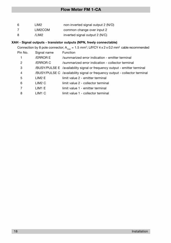
XAH - Signal outputs - transistor outputs (NPN, freely connectable)
Connection by 8 pole connector; Amax = 1.5 mm2; LifYCY 4 x 2 x 0.2 mm2 cable recommended
Pin No. Signal name Function
1 /ERROR E /summarized error indication - emitter terminal
2 /ERROR C /summarized error indication - collector terminal
3 /BUSY/PULSE E /availability signal or frequency output - emitter terminal
4 /BUSY/PULSE C /availability signal or frequency output - collector terminal
5 LIM2 E limit value 2 - emitter terminal
6 LIM2 C limit value 2 - collector terminal
7 LIM1 E limit value 1 - emitter terminal
8 LIM1 C limit value 1 - collector terminal
Flow Meter FM 1-CA
Installation 19
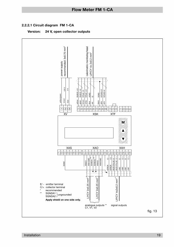
2.2.2.1 Circuit diagram FM 1-CA
Version: 24 V, open collector outputs
fig. 13
* recommended** SGNDA1
SGNDA2Apply shield on one side only.
E/
-
C/
+
E/
-
C/
+
/ER
RO
R
/ER
RO
R
/BU
SY
/PU
LSE
/BU
SY
/PU
LSE
LIM
2
LIM
2
LIM
1
LIM
1
yello
w/g
reen
bro
wn
blu
e
1 2 3 1 2 3 4
XV XSK XTF
XAS XAO XAH
1 2 3 4 5 6 7 8 9 101 2 3
87654321 87654321 87654321
+24
V
0 V
reco
mm
ende
d: 3
x0.7
5 m
m2
SG
ND
A2 **
AN
AO
2
AN
A2G
ND
AN
AO
1
AN
A1G
ND
SG
ND
A1 **
LifY
CY
4x
2x0.
2 m
m2
M
R(H
EIZ
) -LO
R(H
EIZ
) -H
I
R(T
ref)
-HI
R(T
ref)
-LO
yello
w
gree
n
bro
wn
whi
te
AG
ND
IS
blu
e
red
SG
ND
R(T
diff
)-LO
R(T
diff
)-H
I
bla
ck
grey
pin
k
LiY
CY
2x0
.25
mm
2 *
LiY
CY
2x0
.25
mm
2 *
signal outputsanalogue outputs **C1, V1, V2
ungrounded
pow
er s
upp
ly
calo
rimet
ric m
onito
ring
head
E/
-
C/+
E/
-
C/
+
SG
ND
LifY
CY
4x2
x0.2
mm
2 *
E/ - emitter terminalC/+ collector terminal
Flow Meter FM 1-CA
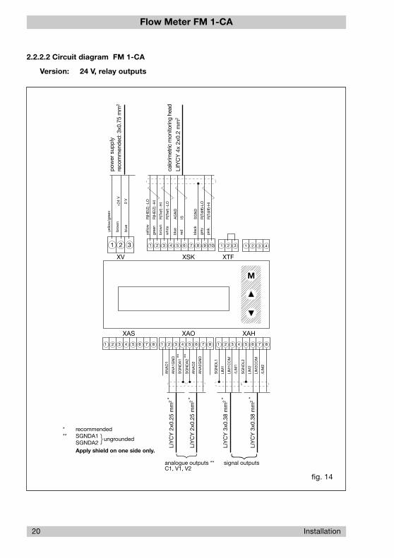
fig. 14
* recommended** SGNDA1
SGNDA2Apply shield on one side only.
yello
w/g
reen
bro
wn
blu
e
1 2 3 1 2 3 4
XV XSK XTF
XAS XAO XAH
1 2 3 4 5 6 7 8 9 101 2 3
87654321 87654321 87654321
+24
V
0 V
reco
mm
ende
d: 3
x0.7
5 m
m2
LiY
CY
3x0
.38
mm
2 *
SG
ND
A2 **
AN
AO
2
AN
A2G
ND
AN
AO
1
AN
A1G
ND
SG
ND
A1 **
LifY
CY
4x
2x0.
2 m
m2
M
R(H
EIZ
) -LO
R(H
EIZ
) -H
I
R(T
ref)
-HI
R(T
ref)
-LO
yello
w
gree
n
bro
wn
whi
te
AG
ND
IS
blu
e
red
SG
ND
R(T
diff
)-LO
R(T
diff
)-H
I
bla
ck
grey
pin
k
SG
ND
L1
LIM
1
LIM
1CO
M
/LIM
1
SG
ND
L2
LIM
2
LIM
2CO
M
/LIM
2
LiY
CY
2x0
.25
mm
2 *
LiY
CY
2x0
.25
mm
2 *
LiY
CY
3x0
.38
mm
2 *
signal outputsanalogue outputs **C1, V1, V2
ungrounded
pow
er s
upp
ly
calo
rimet
ric m
onito
ring
head
20 Installation
2.2.2.2 Circuit diagram FM 1-CA
Version: 24 V, relay outputs

Flow Meter FM 1-CA
fig. 15
XAS XAO XAH
87654321 87654321 87654321
i L ≤
10 m
A
UV
CD
Installation 21
2.2.2.3 Electrical connection - Frequency output (version FM 1-CA-U1T4)
The quantity-dependent pulse to operate a counter or higher-order control is available at con-nector XAH /BUSY E/- and /BUSY C/+ (pins 3 and 4), see fig. 13 - Circuit diagram FM 1-CA -Open collector outputs.
Signal ground shall be connected to pin 3 (BUSY E/-) and the driving load to pin 4 (BUSY C/+).
Select cable sizes ≤1.5 mm2 to make the connections.
The shield cables can be connected to connector XAS, pin 3.
Electronic signal processing
If the frequency output of the FM 1-CA is connected to an electronic counter, computer or PLC,the load current should not exceed 10 mA so as to ensure low level is 0.8 V. The max. admis-sible voltage level of 48 V is irrelevant in this connection.
Typical circuit (example 1)
The FM 1-CA driver output comprises an integral safety circuit which when isolating the coun-ter operating coil will limit overvoltages caused by inductance and convert the energy stored.
The counter should be able of processing a counting frequency of ≥10 Hz.
Flow Meter FM 1-CA
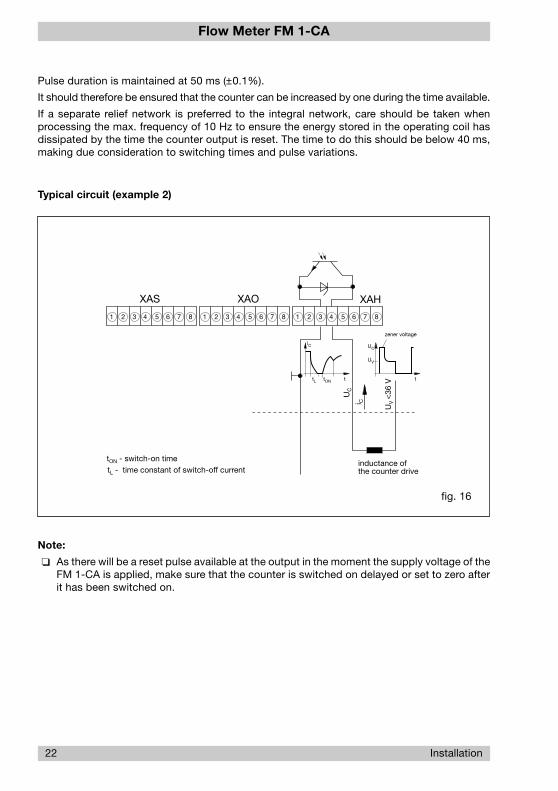
22 Installation
fig. 16
XAS XAO XAH
87654321 87654321 87654321
i C
UV
<36
V
inductance ofthe counter drive
iC
tL tON t
UC
UV
t
zener voltage
UC
tON - switch-on timetL - time constant of switch-off current
Pulse duration is maintained at 50 ms (±0.1%).
It should therefore be ensured that the counter can be increased by one during the time available.
If a separate relief network is preferred to the integral network, care should be taken whenprocessing the max. frequency of 10 Hz to ensure the energy stored in the operating coil hasdissipated by the time the counter output is reset. The time to do this should be below 40 ms,making due consideration to switching times and pulse variations.
Typical circuit (example 2)
Note:
As there will be a reset pulse available at the output in the moment the supply voltage of theFM 1-CA is applied, make sure that the counter is switched on delayed or set to zero afterit has been switched on.

Flow Meter FM 1-CA
Operation 23
fig. 17
3 Operation
3.1 Operating system
Clear menu-driven control, via keyboard and display, enables easy definition of parametersand configuration. This provides high system flexibility, making the FM 1-CA the optimum solutionfor a wide variety of measuring, monitoring and display tasks.
All functions are distributed on the three following menu levels:
MAIN LEVEL (MENU)
CONFIGURATION LEVEL (MENU)
PARAMETER SELECTION (MENU)
See Appendix 2 listing all functions available.
Touch switches
Setting and configuration is by means of three front touch switches: M MODE, UP and DOWN.
Caution!
The FM 1-CA can only be set or operated when connector XTF (keyboard release) is re-moved!
M MODE
UP
DOWNFM 1-CA FLOW MONITOR

Flow Meter FM 1-CA
24 Operation
Menu paging
The next menu option is selected by pressing M MODE (forward paging).
Pressing M MODE after the last menu option will cause skipping to the first option of the menu.
Calling a menu option
Simultaneously pressing UP and DOWN calls the selected menu option, or causes skippingto the selected submenu.
Entry of numerals
Some menu options require numerical values to be entered. After selecting the appropriatemenu option, the value indicated can be changed by pressing UP or DOWN.
Each time UP or DOWN are pressed, the value indicated will be increased and reducedrespectively, by one numeral skip. The longer UP or DOWN are pressed, the faster theincrease or reduction.
Transfer of entries
Pressing M MODE transfers the set value or the selected menu option to a volatile memory. Apermanent transfer of settings and values is only effected when quitting the menu, after aplausibility check of all entries.
Afterwards the data will be available even after repeated on/off operation of the FM 1-CA.
Deleting data
Selected data such as MIN and MAX values can be deleted or reset by simultaneously pressing UP and DOWN.

Flow Meter FM 1-CA
3.1.1 Configuration
The CONFIGURATION submenu serves to adjust the FM 1-CA to its application.
During system configuration, measuring operations are not possible (see Appendix 1).
Configuration possibilities are:
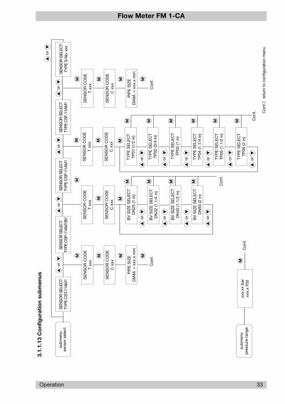
3.1.1.1 Selection of monitoring head (menu option: SENSOR SELECT)
This menu option allows the selection of the monitoring head types suitable for compressed airapplications:
* TYPE CST-11AM1 thread-mounted head for gases
* TYPE CSP-11AM1BV insertion head with ball valves
* TYPE CSP-11AM1 insertion head with sensor adapter TP-..
* TYPE S-No. xxx custom designed monitoring head
Note:
Monitoring head S-No. xxx is only available where a custom designed option has beenordered and integrated.
This menu option also allows to enter the C and T values ensuring the exchangeability of themonitoring heads. Pipe diameter assignment as required for volume flow measurements shouldalso be entered.
Enter the following characteristics when selecting a CST or CSF monitoring head. The settingis menu driven:
1. SENSOR CODE C xxx range: 001 … 999
2. SENSOR CODE T xxx range: 500 … 999
These characteristics are marked on the monitoring head.
Caution:
Observe correct settings as they have a major influence on measuring accuracy.
* PIPE SIZE (DIAM. = xxx.xx mm) range 10.0 … 999.9 mm for monitoring headsCST and CSF
Enter the following characteristics when selecting a CSP monitoring head with ball valve:
* SENSOR CODE C xxx range: 001 … 999
* SENSOR CODE T xxx range: 500 … 999
The nominal diameter of the ball valve is selected in menu option BV SIZE SELECT.
Available sizes are:
* DN25 ( 1 in), DN32 (1 1/4 in), DN40 (1 1/2 in), DN50 (2 in).
Enter the following characteristics when selecting a CSP monitoring head with sensor adapter TP-..:
* SENSOR CODE C xxx range: 001 … 999
* SENSOR CODE T xxx range: 500 … 999
Operation 25
Flow Meter FM 1-CA
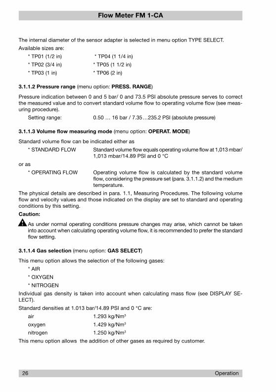
The internal diameter of the sensor adapter is selected in menu option TYPE SELECT.
Available sizes are:
* TP01 (1/2 in) * TP04 (1 1/4 in)
* TP02 (3/4 in) * TP05 (1 1/2 in)
* TP03 (1 in) * TP06 (2 in)
3.1.1.2 Pressure range (menu option: PRESS. RANGE)
Pressure indication between 0 and 5 bar/ 0 and 73.5 PSI absolute pressure serves to correctthe measured value and to convert standard volume flow to operating volume flow (see meas-uring procedure).
Setting range: 0.50 … 16 bar / 7.35…235.2 PSI (absolute pressure)
3.1.1.3 Volume flow measuring mode (menu option: OPERAT. MODE)
Standard volume flow can be indicated either as
* STANDARD FLOW Standard volume flow equals operating volume flow at 1,013 mbar/1,013 mbar/14.89 PSI and 0 °C
or as
* OPERATING FLOW Operating volume flow is calculated by the standard volumeflow, considering the pressure set (para. 3.1.1.2) and the mediumtemperature.
The physical details are described in para. 1.1, Measuring Procedures. The following volumeflow and velocity values and those indicated on the display are set to standard and operatingconditions by this setting.
Caution:
As under normal operating conditions pressure changes may arise, which cannot be takeninto account when calculating operating volume flow, it is recommended to prefer the standardflow setting.
3.1.1.4 Gas selection (menu option: GAS SELECT)
This menu option allows the selection of the following gases:
* AIR
* OXYGEN
* NITROGEN
Individual gas density is taken into account when calculating mass flow (see DISPLAY SE-LECT).
Standard densities at 1.013 bar/14.89 PSI and 0 °C are:
air 1.293 kg/Nm3
oxygen 1.429 kg/Nm3
nitrogen 1.250 kg/Nm3
This menu option allows the addition of other gases as required by customer.
26 Operation
Flow Meter FM 1-CA
Operation 27
3.1.1.5 Limit switch combinations (menu option: LIMIT SWITCHES)
The FM 1-CA comprises two limit switches which are assigned to the physical quantity/quan-tities to be monitored in menu “LIMIT SWITCHES”.
The following four combinations are available:
* LS1 → F LS2 → FLimit switch 1 → flow rateLimit switch 2 → flow rate
* LS1 → T LS2 → TLimit switch 1 → medium temperatureLimit switch 2 → medium temperature
* LS1 → F LS2 → TLimit switch 1 → flow rateLimit switch 2 → medium temperature
* LS1 → T LS2 → FLimit switch 1 → medium temperatureLimit switch 2 → flow rate
Mode of operation, limit value and hysteresis of the limit switches are set in menu “PARAM-ETER SELECTION”.
Caution:
Menu option “LIMIT SWITCHES” may influence data in the parameter selection menu (seepara. 3.1.1.11, Quitting the configuration menu).
3.1.1.6 Flow rate unit (menu option: FLOW UNIT)
This menu option is used to set the desired flow rate unit:
* METRE/SEC [m/s] * FEET/SEC. [FPS]
* PERCENT [%] * BLANK [no unit]
Any further entries relating to flow rate (e.g. limit value, analogue output etc.) refer to that unit.
Standard percent is displayed when BLANK (no unit) is selected.
When the flow rate unit is changed, all configuration and parameter data relating to flow ratewill automatically be converted!
3.1.1.7 Medium temperature unit (menu option: TEMP. UNIT)
This submenu is used to select medium temperature unit:Options are:
* GRAD CELSIUS [°C]
* GRAD FAHRENHEIT [°F]
* KELVIN [K]
All other entries relating to the medium temperature (limit value, analogue output etc.) refer tothe unit selected there. When the temperature unit is changed, all configuration and parameterdata relating to medium temperature will automatically be converted.

Flow Meter FM 1-CA
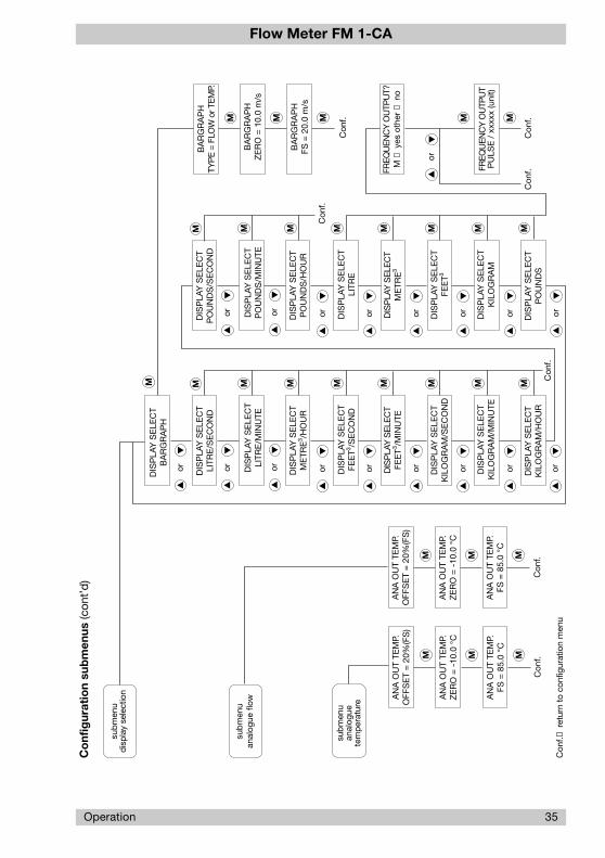
3.1.1.8 Display (menu option: DISPLAY SELECT)
The FM 1-CA enables the user to define certain points of the display.
When the first line of the LC display in the main menu indicates the flow rate in the unit selectedas well as the medium temperature in °C, °F, or K, it is possible to select the 2nd line from thefollowing menu options:
* BARGRAPH Totalizer:
* LITRE/SECOND [l/s] * LITRE [ l ]
* LITRE/ MINUTE [L/min] * METRE3 [m3]
* METRE3 / HOUR [m3/h] * FEET3 [F3]
* GALLONS°/ MINUTE * KILOGRAM [kg]
* FEET3 / SECOND [F 3/s] * POUND [ lb]
* FEET3 / MINUTE [F 3/min]
* KILOGRAM/SECOND [kg/s]
* KILOGRAM/MINUTE [kg/min]
* KILOGRAM/HOUR [kg/h]
* POUND/SECOND [lb/s]
* POUND/MINUTE [lb/min]
* POUND/HOUR [lb/h]
Where totalizer function has been selected, the totalizer will start at zero counting in the unitselected.
When the display changes, the value already counted will be converted.
The content of the totalizer is deleted by simultaneously pressing UP and DOWN, or whenthe max. display value (99999999.9) is reached. In both cases, the totalizer will restart fromzero.
Caution:
The content of the totalizer is deleted in the event of power failure or disconnection of thepower supply!
3.1.1.8.1 Bar graph (menu option: BARGRAPH)
This menu option allows the user to set the bar graph as desired. The following settings shouldbe made:
* FLOW / TEMP = (bar graph assignment: flow rate/medium temperature)
* ZERO = (initial value of the bar graph)
* FS = (final value of the bar graph)
Independent of its assignment, the bar graph has a constant resolution of 10 segments.
When entering the initial or final value, the user should observe a reasonable resolution!
The bar graph also comprises the representation of the limit switch(es) as far as they can beindicated in the bar range selected.
28 Operation

Flow Meter FM 1-CA
Operation 29
The representation of the limit switches in the bar graph depends on the switch-on value of thelimit switch.
For representation details see para. 4.2.1 (Operating data).
Example:
Limit switch assignment: LS1 → F LS2 → T
Switch-on value LS2: +23 °CAnalogue bar graph assignment: medium temperature
Initial value - analogue bar graph: +20 °CFinal value - analogue bar graph: +30 °CInstantaneous temperature value: +25 °C→ resulting in the analogue bar graph display shown below.
fig. 17
20 °C 21 °C 25 °C 29 °C 30 °C
LS2 ON
T
3.1.1.8.2 Frequency output (menu option: FREQUENCY OUTPUT)
The totalizer function of the FM 1-CA has been expanded by the output of proportional quantitypulses. The function can only be displayed by version FM 1-CA-U1T4 (open collector outputs).
The proportional quantity pulses have been determined as follows:
1 pulse / quantity (totalizer unit selected)
Example: 1 pulse / 10.0 [litre]
The frequency output will supply 1 pulse per 10 litres (totalized quantity).
When the quantity-proportional pulses are assigned, the frequency of the frequency outputmust no exceed 10 Hz. The limits that can be displayed are determined by the flow velocityrange and the pipe diameter.
Potential setting range of the frequency output: 1 pulse per 0.1 … 999.9 [litre], [m3], [F3], [kg], [lb]
Flow Meter FM 1-CA
30 Operation
Behaviour of the frequency output when the max. frequency is exceeded
The max. frequency being exceeded will not cause the measurement to stop but will rathercause the error output to signal error 60 on the display. This error is included in priority group III.
If a combination of priority III errors occurs simultaneously, they are indicated or stored in theerror memory observing the following sequence:
Error No. 20, 30, 60, 40, 41.
Behaviour of the frequency output when the measurement is stopped
When the measurement is stopped (as caused by priority II error and calling the configurationor parameter selection menus), the pulses for the quantity already counted will be available.Thereafter the output of pulses will be stopped, with the frequency output becoming high-resistive until the measurement is restarted.
Behaviour of the frequency output when the content of the totalizer is deleted
The content of the totalizer may be deleted by simultaneously pressing UP and DOWN inthe main menu.
As the frequency output refers to the content of the totalizer, although its operation is notdependent on the content of the totalizer, a totalized quantity that is smaller than that set perpulse will not be lost.
This means that only the content of the totalizer is deleted.
3.1.1.9 Analogue output - flow rate (menu option: ANA OUT FLOW)
This menu option allows adjustment of the flow rate analogue output specifically to the require-ments of the entire system.
Options are:
* OFFSET = % (FS) (0/4 … 20 mA, 0/1 … 5 V, 0/2 … 10 V)
* ZERO = (initial value 0(20) % corresponds to a flow rate of … [m/s] [%])
* FS = (100 % final value corresponds to a flow rate of… [m/s] [%])
When entering the initial value, the user should observe a reasonable resolution!
With a flow volume/time unit selected in menu DISPLAY SELECT and when setting the initialand end values, the pertinent flow volumes will also be indicated.
3.1.1.10 Analogue output - medium temperature (menu option: ANA OUT TEMP.)
In conformance with the configuration “Flow rate analogue output” it is possible to adjust themedium temperature analogue output to the requirements of the entire system.
Options are:
* OFFSET = % (FS) (0/4 … 20 mA, 0/1 … 5 V, 0/2 … 10 V)
* ZERO = (initial value 0(20) % corresponds to a medium temperature of … [°C] [°F] [K])
* FS = (100 % final value corresponds to a medium temperature of … [°C] [°F] [K])
When entering the initial or final value, the user should observe a reasonable resolution!
Flow Meter FM 1-CA
Operation 31
3.1.1.11 Quitting the configuration menu
Upon configuration of the analogue outputs, the menu may be quitted or reset to the start (SENSORSELECT).
To quit the configuration menu, the controller will check the data entered for plausibility.
“CONFIG. OK!” is indicated when the data are found to be correct. The menu may then bequitted by pressing M MODE.
Errors found during the plausibility check are indicated in the following sequence of priority.
Priority of entry errors in the CONFIGURATION menu:
* ERR. A-OUT FLOW OUT OF RANGE (flow analogue output outside measuring range)
* ERR. A-OUT FLOW ZERO ≥ FS (initial value ≥ final value with flow analogue output)
* ERR. A-OUT TEMP. OUT OF RANGE (temperature analogue output outside measuring range)
* ERR. A-OUT TEMP. ZERO ≥ FS (initial value ≥ final value with temperature analogue output)
* ERR. BARGRAPH OUT OF RANGE (bar value outside measuring range)
* ERR. BARGRAPH ZERO ≥ FS (bar initial value ≥ bar final value)
The menu can only be quitted after correction of the error(s). To do this, return to the beginningof the configuration menu by pressing DOWN or UP and select the menu option with theincorrect entry for correction.
Caution:
If during the configuration data are affected which are accessible in the parameter selec-tion menu (which may be the case for the options Sensor Selection, Medium Selection andLimit Switch Assignment), the option “PARAMETERS” in the main menu will be flashing.
In this event it is imperative to branch into parameter selection menu to set the data inconformance with the desired application.
Example : Changing the limit switch assignment from LS1 → F / LS2 → T toLS1 → F / LS2 → F
affects LS2 ON = 0.00
Parameter data: LS2 OFF = end of measuring range
Reason: Changing the physical assignment of limit switch 2 will adjust itsswitch-on and switch-off values to the new assignment (flow rate).
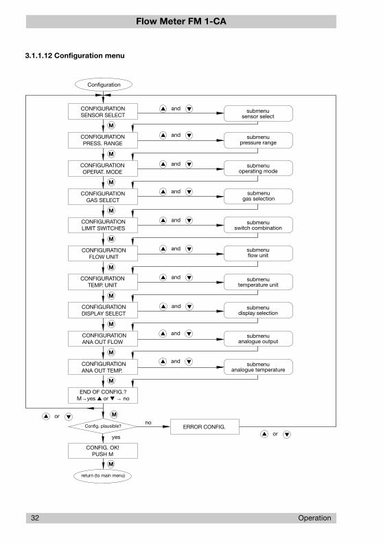
An overview of the configuration menu and a summary of the measuring ranges and menusavailable for the sensor type selected are shown on the following pages.
Flow Meter FM 1-CA
32 Operation
END OF CONFIG.?M→yes or → no
CONFIGURATIONANA OUT TEMP.
and
and
CONFIGURATIONANA OUT FLOW
CONFIGURATIONDISPLAY SELECT
CONFIGURATIONTEMP. UNIT
CONFIGURATIONFLOW UNIT
and
CONFIGURATIONOPERAT. MODE
Configuration
submenupressure range
submenusensor select
submenuflow unit
submenuoperating mode
submenudisplay selection
submenutemperature unit
submenuanalogue temperature
submenuanalogue output
noERROR CONFIG.
return (to main menu)
CONFIG. OK!PUSH M
Config. plausible?
yes
CONFIGURATIONSENSOR SELECT
CONFIGURATIONPRESS. RANGE
and
and
and
and
and
or
M
or
CONFIGURATIONGAS SELECT
submenuswitch combination
CONFIGURATIONLIMIT SWITCHES
M
M
M
M
M
M
M
M
M
M
M
submenugas selection
and
and
3.1.1.12 Configuration menu
Flow Meter FM 1-CA
Operation 33
SE
NS
OR
CO
DE
T xx
x
M
SE
NS
OR
CO
DE
C x
xx
PIP
E S
IZE
DIA
M. =
xxx
.x m
m
M
Con
f.MM
SE
NS
OR
CO
DE
T xx
x
SEN
SO
R S
ELEC
TTY
PE
CS
T-11
AM
1
3.1.
1.13
Co
nfig
urat
ion
sub
men
us
sub
men
use
nsor
sel
ect
Con
f.→ re
turn
to
conf
igur
atio
n m
enu
sub
men
up
ress
ure
rang
e
MC
onf.
M
SEN
SOR
SEL
ECT
TYPE
CSP
-11A
M1B
VS
ENS
OR
SEL
ECT
TYP
E C
SP
-11A
M1
SEN
SO
R S
ELEC
TTY
PE
CS
F-11
AM
1
SE
NS
OR
CO
DE
C x
xx
BV
SIZ
E S
ELE
CT
DN
25 (1
in)
BV
SIZ
E S
ELE
CT
DN
32 (1
.1/4
in)
BV
SIZ
E S
ELE
CT
DN
40 (1
.1/2
in)
BV
SIZ
E S
ELE
CT
DN
50 (2
in)
TYP
E S
ELE
CT
TP05
(1.1
/2 in
)
TYP
E S
ELE
CT
TP06
(2 in
)
Con
f.
M
SE
NS
OR
CO
DE
T xx
x M
SE
NS
OR
CO
DE
C x
xx
TYP
E S
ELE
CT
TP01
(1/2
in)
TYP
E S
ELE
CT
TP02
(3/4
in)
TYP
E S
ELE
CT
TP03
(1 in
)
TYP
E S
ELE
CT
TP04
(1.1
/4 in
)
M
M
SE
NS
OR
CO
DE
T xx
x
M
SE
NS
OR
CO
DE
C x
xx
PIP
E S
IZE
DIA
M. =
xxx
.x m
m
xxx.
xx b
arxx
x.x
PS
I
M
Con
f.M
Con
f.
MMM
MMMM MM
MM
M
SEN
SO
R S
ELEC
TTY
PE
S-N
o. x
xx
or
or
or
or
or
or
or
or
or
or
or
or
or
or
or

Flow Meter FM 1-CA
34 Operation
Co
nfig
urat
ion
sub
men
us (c
ont’
d)
Con
f.→ re
turn
to
conf
igur
atio
n m
enu
GA
S S
ELE
CT
AIR
sub
men
uga
s se
lect
ion
GA
S S
ELE
CT
NIT
RO
GE
N
M
Con
f.
GA
S S
ELE
CT
OX
YG
EN
Con
f.
MM
Con
f.
LIM
IT S
WIT
CH
ES
LS1
→ T
LS
2 →
FLI
MIT
SW
ITC
HE
SLS
1 →
F L
S2
→ T
LIM
IT S
WIT
CH
ES
LS1
→ T
LS
2 →
TLI
MIT
SW
ITC
HE
SLS
1 →
F L
S2
→ F
sub
men
ulim
it sw
itch
com
bin
atio
n
M
Con
f.C
onf.
M
Con
f.C
onf. M
M
TEM
P. U
NIT
CE
LSIU
S (°
C)
sub
men
ute
mp
erat
ure
unit
TEM
P. U
NIT
FAH
RTE
NH
EIT
(°F)
M
Con
f.
TEM
P. U
NIT
KE
LVIN
(K)
Con
f.
MM
Con
f.
OP
ER
AT. S
ELE
CT
STA
ND
AR
D F
LOW
sub
men
uop
erat
ing
mod
eO
PE
RAT
. SE
LEC
TO
PE
RAT
ING
FLO
W
xx.x
x b
ar/x
xx.x
PS
IM
EA
SU
RE
D T
EM
P.1.
01 b
ar /1
4.7
PS
I0.
0 °C
/ 3
2.0
°F
Con
f.
MM
MM
Con
f.
FLO
W U
NIT
BLA
NK
(no
unit)
FLO
W U
NIT
FEE
T/S
EC
(FP
S)
FLO
W U
NIT
ME
TRE
/SE
C (m
/s)
FLO
W U
NIT
PE
RC
EN
T (%
)su
bm
enu
flow
uni
t
M
Con
f.C
onf.
M
Con
f.C
onf. M
M
or
or
or
or
or
or
or
or
or
or
or
or
or
or
or
or
Flow Meter FM 1-CA
Operation 35
DIS
PLA
Y S
ELE
CT
KIL
OG
RA
M/H
OU
R
DIS
PLA
Y S
ELE
CT
FEE
T3 /SE
CO
ND
or DIS
PLA
Y S
ELE
CT
KIL
OG
RA
M/M
INU
TE
Con
f.
or
or
or
or
orDIS
PLA
Y S
ELE
CT
FEE
T3 /MIN
UTE
DIS
PLA
Y S
ELE
CT
KIL
OG
RA
M/S
EC
ON
D
MMMM MM
DIS
PLA
Y S
ELE
CT
LITR
E/S
EC
ON
D
M
DIS
PLA
Y S
ELE
CT
LITR
E/M
INU
TE
DIS
PLA
Y S
ELE
CT
ME
TRE
3 /HO
UR
M
or
or
Co
nfig
urat
ion
sub
men
us (c
ont’
d)
Con
f.→ re
turn
to
conf
igur
atio
n m
enu
BA
RG
RA
PH
TYP
E =
FLO
W o
r TEM
P.
sub
men
udi
spla
y se
lect
ion
M
BA
RG
RA
PH
ZE
RO
= 1
0.0
m/s
M
BA
RG
RA
PH
FS =
20.
0 m
/s
Con
f.
M
M
DIS
PLA
Y S
ELE
CT
PO
UN
DS
DIS
PLA
Y S
ELE
CT
LITR
E
or DIS
PLA
Y S
ELE
CT
KIL
OG
RA
M
Con
f.
or
or
or
or
orDIS
PLA
Y S
ELE
CT
ME
TRE
3
DIS
PLA
Y S
ELE
CT
FEE
T3
MMMM MM
DIS
PLA
Y S
ELE
CT
PO
UN
DS
/SE
CO
ND
M
DIS
PLA
Y S
ELE
CT
PO
UN
DS
/MIN
UTE
DIS
PLA
Y S
ELE
CT
PO
UN
DS
/HO
UR
M
or
or
sub
men
uan
alog
uete
mp
erat
ure A
NA
OU
T TE
MP.
OFF
SE
T =
20%
(FS
)
M M
Con
f.M
AN
A O
UT
TEM
P.Z
ER
O =
-10
.0 °
C
AN
A O
UT
TEM
P.FS
= 8
5.0
°C
sub
men
uan
alog
ue fl
ow
AN
A O
UT
TEM
P.O
FFS
ET
= 2
0%(F
S)
M M
Con
f.M
AN
A O
UT
TEM
P.Z
ER
O =
-10
.0 °
C
AN
A O
UT
TEM
P.FS
= 8
5.0
°C
or
DIS
PLA
Y S
ELE
CT
BA
RG
RA
PH
Con
f.
FREQ
UEN
CY
OU
TPU
TP
ULS
E /
xxx
xx (u
nit)
or
FREQ
UEN
CY
OU
TPU
T?M
→ y
es o
ther
→ n
o
M
Con
f.
M

Flow Meter FM 1-CA
36 Operation
fig. 19
switching conditionof limit switch 1
switch-off value
measured value
switch-on value
hysteresis
0
ON
∞
OFF
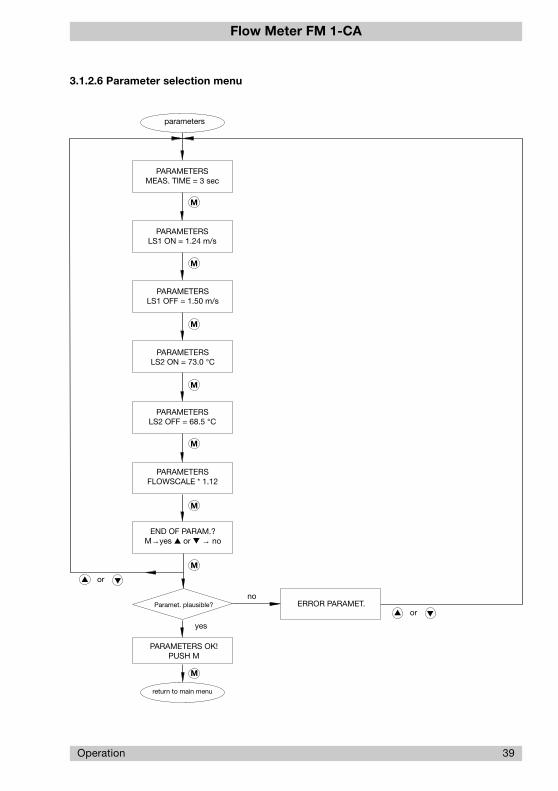
3.1.2 Parameter selection
After configuration of the FM 1-CA in conformance with its application (configuration menu), itis possible to set parameters (e.g. limit values).
During parameter setting, measuring operations are not possible (see Appendix 1).
The following parameters may be set in the Parameter selection submenu:
3.1.2.1 Measuring time (menu option: MEAS. TIME)
The measuring time may be between 1 and 30 sec., referring both to flow rate and mediumtemperature.
The effect of the measuring time may be compared to that of a filter; it is used to determine theaverage of the last measured values after each measurement.
The set measuring time does not influence the measuring rate and display up-date.
3.1.2.2 Limit switch 1 - switch-on value (menu option: LS1 ON = ......)
Limit switch 1 - switch-off value (menu option: LS1 OFF = ......)
Depending on the configuration (see configuration menu) limit value 1 may be set either for flowrate or medium temperature.
The limit value may be set over the entire measuring range and is always related to the displayvalue.
Limit switch up-date is by measuring rate, independent of the set measuring time.
The hysteresis is determined by entering different switch-on and switch-off values. Its magni-tude should be reasonably adjusted to current operating conditions.
A specific definition of the operation (closed-current or open-circuit principle) may be droppedby separately entering the switch-on and switch-off value of the limit switch, because the defi-nition is deducted from the switch-on and switch-off value.
Example 1: Switch-on value lower than switch-off value

Flow Meter FM 1-CA
Operation 37
Example 2: Switch-on value higher than switch-off value
fig. 20
switching conditionof limit switch 1
switch-off value
measured value
switch-on value
hysteresis
0
ON
∞
OFF
With limit switch 1 set for flow rate and a flow volume/time unit selected in menu DISPLAY SELECT,and when setting the switch-on and switch-off value, the pertinent flow volumes will also beindicated.
3.1.2.3 Limit switch 2 - switch-on value (menu option: LS2 ON = ......)
Limit switch 2 - switch-off value (menu option: LS2 OFF = ......)
See limit switch 1!
3.1.2.4 Scaling factor (menu option: FLOWSCALE*)
The scaling factor influences flow rate indication.
The factor, which may be set between 0.01 and 9.99, allows flow rate indication changes (in-creasing or reducing the measured value in the display).
For example, the scaling factor may be used to indicate the average flow rate in the pipelinerather than that available at the sensor.
3.1.2.5 Quitting the parameter selection menu
Before the parameter menu can be quitted, the controller will conduct a plausibility check ofthe data entered.
“PARAMETERS OK!” is indicated when the data are found to be correct. The menu may thenbe quitted by pressing M MODE.
Errors found during the plausibility check are indicated in the following sequence of priority.
Priority of entry errors in the PARAMETER SELECTION menu:
* ERROR LS1 OUT OF RANGE switch-on and/or switch-off value for limit switch 1 outside measuring range

Flow Meter FM 1-CA
38 Operation
* ERROR LS2 OUT OF RANGE switch-on and/or switch-off value for limit switch 2 outside measuring range
* ERROR LS1 ON = OFF switch-on value for limit switch 1 equals switch-off value for limit switch 1
* ERROR LS2 ON = OFF switch-on value for limit switch 2 equals switch-off value for limit switch 2.
The menu can only quitted after correction of the error(s). To do this, return to the beginning ofthe parameter selection menu by pressing DOWN or UP and select the menu option withthe correct entry for correction.
An overview of the parameter selection menu is shown on the following page.
Flow Meter FM 1-CA
3.1.2.6 Parameter selection menu
Operation 39
PARAMETERS OK!PUSH M
no
return to main menu
M
yes
or
M
or
M
M
PARAMETERSFLOWSCALE * 1.12
PARAMETERSLS2 OFF = 68.5 °C
PARAMETERSLS2 ON = 73.0 °C
parameters
PARAMETERSMEAS. TIME = 3 sec
END OF PARAM.?M→yes or → no
ERROR PARAMET.Paramet. plausible?
PARAMETERSLS1 ON = 1.24 m/s
PARAMETERSLS1 OFF = 1.50 m/s
M
M
M
M
Flow Meter FM 1-CA
40 Operation
3.2 Low flow suppression
The low flow suppression menu option serves to suppress small flow quantities and to detectleakages. Menu settings can be changed during the measuring operation, requiring no addi-tional heating period.
3.2.1 Low flow suppression
The low flow suppression option ranging from 1 to 10 % of the measuring range final value canbe used to eliminate false measurements as may arise upon (small) reverse flow quantities, forexample. If flow velocity is less than the value set, the flow velocity and the applicable flow isset at zero. This also applies to all subsequent quantities such as analogue output, bar graphand limit switches which are defined in the other menus.
3.2.2 Zero adjustment
Although because of its very special characteristic curve in the lower flow range the calorimetricprocedure implies a higher resolution than other measuring procedures, it is not possible to exactlymeasure zero flow, the reason for this being that in the lower flow range (<1 % of measuringrange final value) current flow is superimposed by convection flow around the heated monitoringhead sensor. Convection flow is very difficult to theoretically detect for all measuring systems(monitoring head and FM 1-CA); it is determined by installation and current pressure and tem-perature, etc. Selecting 0 % will therefore always result in zero adjustment.
To ensure correct zero adjustment, the pipeline should be operated under the desired pressureand temperature conditions, and a waiting period of approx. 2 … 5 minutes should be observedafter the pipe system has been closed (zero volume flow) to ensure correct setting. If the FM 1-CAindicates flow after pipeline has been opened, there is definitely flow available. After this ad-justment even smallest volume flow quantities can be reliably indicated.
Caution:
No plausibility test to ensure there is no volume flow is conducted for zero adjustment. Thevolume flow available at that time is set at zero. This should be considered above all foruntight valves in which case the zero volume flow determined this way may even be greaterthan 1 %. Accuracy in the lower measuring range will decrease then. To be on the safe side,the lower limit should therefore be set at 1 % if no reliable zero adjustment can be made.

Flow Meter FM 1-CA
On-line phases 41
4 On-line phases
4.1 Switch-on performance
Upon power application, POWER ON TEST will be shown on the display for approx. 1 sec, withthe software version number being indicated in the second line.
During this period, the integral controller will conduct test routines (see para. 5.1, Test anddiagnosis).
If during the test no error was found, the display will indicate either HEATING UP.
The FM 1-CA will then be in the heating up period required for the measuring procedure.
4.2 Measuring cycle
Upon completion of the heating up period and availability of the first measured value, the displaywill change to measuring cycle, and the user interfaces such as analogue outputs or limit switcheswill be up-dated.
Over limits of the measuring range
Theoretically established measuring values will be used when the measuring range is exceeded(0 ...68 Nm/s for air). The FM 1-CA can thus be operated beyond the measuring values defined.
This feature will not affect the accuracy specified for the measuring ranges defined whilst noaccuracy information can be given for conditions where the measuring ranges are exceeded.
Analogue output, limit switches etc. can be set above the measuring range of 100%.
The following operating data may be retrieved in the main menu during the measuring cycle:
4.2.1 Operating data
4.2.1.1 Measured value(s)
Flow rate and medium temperature are indicated by the units selected in the upper line of theLC display.The lower line of the display will optionally show the switching condition of the limit switchesand an analogue bar with a 10-segment resolution, or the flow volume/time unit pertinent to theindicated flow rate or the totalized flow volume (totalizer function).
The analogue bar has different meanings, depending on its configuration (see para. 3.1.1.8.1 -menu option BARGRAPH).
The limit switches are identified according to their physical assignment, i.e. by F for flow rateand T for medium temperature, at the first or last place of the second line on the display.
If F and T are shown reversed, the limit switch is in the switch-on condition.
Limit switches lying within the analogue bar range are also represented at the appropriateplace of the analogue bar (see para. 3.1.1.8.1).

Flow Meter FM 1-CA
42 On-line phases
The following figures show the display variants under the menu option “Measured Value(s)”(para. 3.1.1.8 - menu option DISPLAY SELECT and 3.1.1.8.2 - menu option FREQUENCYOUTPUT).
fig. 21
inverse representation“switch-on condition”
5.0 m/s -13.5 °C
TFF
TF
TF
TF
1332.4 m3/h
370.1 l/s
22206.9 l/min
TF
TF
37004567.9 l
3704.6 m3
5.0 m/s -13.5 °C
5.0 m/s -13.5 °C
5.0 m/s -13.5 °C
5.0 m/s -13.5 °C
5.0 m/s -13.5 °C
TF 3704567.9 m35.0 m/s -13.5 °C
P
frequency output selected (PULSE)
Flow Meter FM 1-CA
On-line phases 43
4.2.1.2 Peak values (menu option: PEAK VALUE MIN / PEAK VALUE MAX)
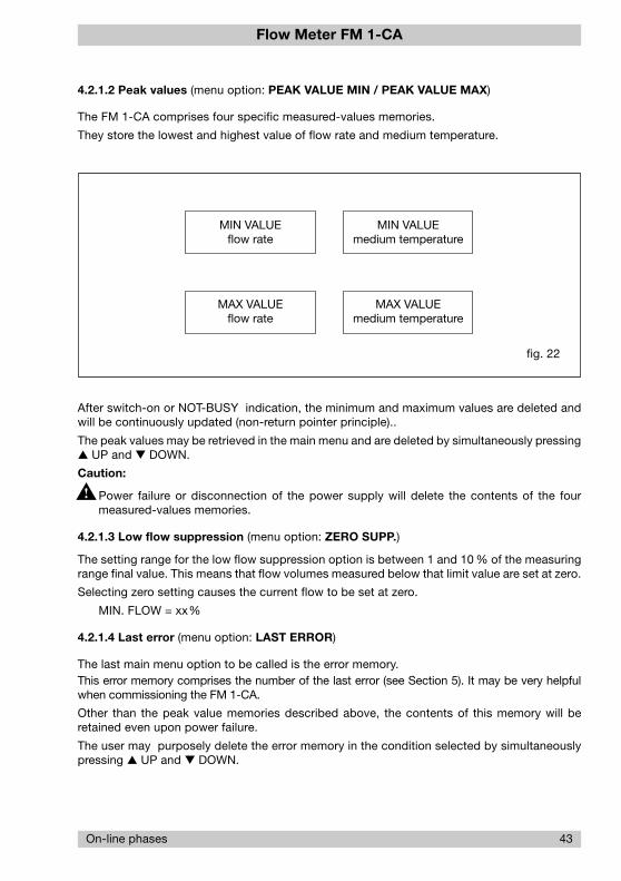
The FM 1-CA comprises four specific measured-values memories.
They store the lowest and highest value of flow rate and medium temperature.
fig. 22
MAX VALUEmedium temperature
MIN VALUEmedium temperature
MAX VALUEflow rate
MIN VALUEflow rate
After switch-on or NOT-BUSY indication, the minimum and maximum values are deleted andwill be continuously updated (non-return pointer principle)..
The peak values may be retrieved in the main menu and are deleted by simultaneously pressing UP and DOWN.
Caution:
Power failure or disconnection of the power supply will delete the contents of the fourmeasured-values memories.
4.2.1.3 Low flow suppression (menu option: ZERO SUPP.)
The setting range for the low flow suppression option is between 1 and 10 % of the measuringrange final value. This means that flow volumes measured below that limit value are set at zero.
Selecting zero setting causes the current flow to be set at zero.
MIN. FLOW = xx%
4.2.1.4 Last error (menu option: LAST ERROR)
The last main menu option to be called is the error memory.This error memory comprises the number of the last error (see Section 5). It may be very helpfulwhen commissioning the FM 1-CA.
Other than the peak value memories described above, the contents of this memory will beretained even upon power failure.
The user may purposely delete the error memory in the condition selected by simultaneouslypressing UP and DOWN.

Flow Meter FM 1-CA
44 On-line phases
4.2.1.5 Main menu
delete errorsstored
TFF
12.5 m/s -13.5 °C
HEATING UP
TFF
power-on
M
12.5 m/s -13.5 °C
LAST ERROR 20
HEATING UP PARAMETERS
menu configuration
menu parameter selection
PEAK VALUE MIN
10.8 m/s -19.5 °C and
M
M
CONFIGURATION
12.5 m/s -13.5 °C and
M
PARAMETERS
12.5 m/s -13.5 °C and
ZERO SUPP.
12.5 m/s -13.5 °C and
M
and
M
PEAK VALUE MAX
14.8 m/s 105 °C delete maximum value(s)
and
HEATING UP LAST ERRORM
submenu zero suppression
delete minimum value(s)

Flow Meter FM 1-CA
Errors 45
5 Errors
5.1 Test and diagnosis
The FM 1-CA is provided with extensive test and diagnosis functions which may be classifiedas follows:
5.1.1 Priority group I
Priority group I comprises the switch-on test routines (FM 1-CA self-test) which are carried outwhen the system is switched on.
Their implementation is indicated.
Errors No. 1 to 5 do not allow system operation.
The test routines may be repeated by pressing any of the switches.
If even after several trials the switch-on test cannot be conducted without error indication, thesystem should be returned to the supplier for rectification, indicating the error number.
Priority I errors cannot be rectified by the user!
5.1.2 Priority group II
These test functions are also continuously carried out during operation. The occurrence oferrors No. 10 and 21 will cause measurements to stop, indicating the error and monitoring thesource of the error. Upon rectification of the error, the system will automatically return to meas-uring operation.
5.1.3 Priority group III
These test routines are also continuously carried out during operation.
Other than the above priority groups, errors No. 20, 30, 60, 40 and 41 will not cause measure-ments to stop; the error output will indicate and the number of the error will be shown on thedisplay.
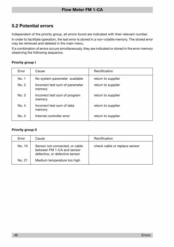
Flow Meter FM 1-CA
5.2 Potential errors
Independent of the priority group, all errors found are indicated with their relevant number.
In order to facilitate operation, the last error is stored in a non-volatile memory. The stored errormay be retrieved and deleted in the main menu.
If a combination of errors occurs simultaneously, they are indicated or stored in the error memoryobserving the following sequence.
Priority group I
Error Cause Rectification
No. 1 No system parameter available return to supplier
No. 2 Incorrect test sum of parameter return to suppliermemory
No. 3 Incorrect test sum of program return to suppliermemory
No. 4 Incorrect test sum of data return to suppliermemory
No. 5 Internal controller error return to supplier
Priority group II
Error Cause Rectification
No. 10 Sensor not connected, or cable check cable or replace sensorbetween FM 1-CA and sensordefective, or defective sensor
No. 21 Medium temperature too high
46 Errors
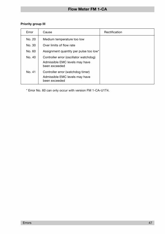
Flow Meter FM 1-CA
Priority group III
Error Cause Rectification
No. 20 Medium temperature too low
No. 30 Over limits of flow rate
No. 60 Assignment quantity per pulse too low*
No. 40 Controller error (oscillator watchdog)
Admissible EMC levels may havebeen exceeded
No. 41 Controller error (watchdog timer)
Admissible EMC levels may havebeen exceeded
* Error No. 60 can only occur with version FM 1-CA-U1T4.
Errors 47

Flow Meter FM 1-CA
48 Directions
6 Directions for calorimetric monitoring heads
These are general directions for the application of calorimetric monitoring heads which fromapplication to application should be reviewed by the user in accordance with individual require-ments.
6.1 Selection of material
6.1.1 Stainless steel 1.4571/AISI 316 Ti
The standard monitoring head material is stainless steel 1.4571, an austenitic, acid resistingstainless steel that is commonly used throughout industry. Manufacturers claim it also with-stands oxidizing organic and anorganic acids, and partly even reductive media.
The resistance of this stainless steel should however be verified by the user, particularly when it isused in medium mixtures that may from time to time be exchanged with cleansing agents. Itschemical resistance also depends on temperature, flow rate and concentration of the medium.
Stainless steel owe their resistance to rust mainly to their alloy combination with chromium, theformation of chromic oxide on the steel surface resulting in a passive state. Contamination,deposits on the surface, or foreign rust may however neutralize the passivity. Therefore careshould be taken to keep the surfaces clean.
Stainless steel heads must not get in contact with steel parts other than stainless steel or withchemically dissimilar metals, as this would cause electrolytic corrosion.
6.1.2 Nickel-based alloy (Hastelloy 2.4610)
Hastelloy 2.4610 is a material with a chemical resistance generally exceeding that of stainlesssteel and copper-based alloys. It is particularly suitable for alkaline media (pH > 7). It shouldhowever be examined for suitability for each specific application using resistance tables andpragmatical values.
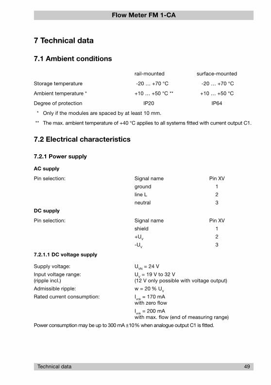
Flow Meter FM 1-CA
Technical data 49
7 Technical data
7.1 Ambient conditions
rail-mounted surface-mounted
Storage temperature -20 … +70 °C -20 … +70 °C
Ambient temperature * +10 … +50 °C ** +10 … +50 °C
Degree of protection IP20 IP64
* Only if the modules are spaced by at least 10 mm.
** The max. ambient temperature of +40 °C applies to all systems fitted with current output C1.
7.2 Electrical characteristics
7.2.1 Power supply
AC supply
Pin selection: Signal name Pin XV
ground 1
line L 2
neutral 3
DC supply
Pin selection: Signal name Pin XV
shield 1
+UV 2
-UV 3
7.2.1.1 DC voltage supply
Supply voltage: UVN = 24 V
Input voltage range: UV = 19 V to 32 V(ripple incl.) (12 V only possible with voltage output)
Admissible ripple: w = 20 % UV
Rated current consumption: Ivnk = 170 mAwith zero flow
Ivnk = 200 mAwith max. flow (end of measuring range)
Power consumption may be up to 300 mA ±10% when analogue output C1 is fitted.

Flow Meter FM 1-CA
50 Technical data
Inrush current: Ip = 3 A (20 µs)
Switch-off current: Ikipp = 0.75 A
Rated power consumption: Pn = 4.1 Wwith zero flow, voltage outputs
Pn = 4.8 Wwith max. flow (end of measuring range)
Insulation voltage: supply input - central electronic unit ≥ 500 V
7.2.1.2 AC supply voltage
Supply voltage: UV = 24 V(rms) ± 10%
Frequency: fV = 40 Hz to 100 Hz
Rated current consumption: Ivn1
= 170 mA to 200 mA
Inrush current: Ip = 4.24 A (20 µs)
Switch-off current: Ikipp = 0.75 A rms
Rated power consumption: Pn = 4.1 VA
Current flow angle: ϕ = 50°
Insulation voltage: supply input - central electronic unit ≥ 500 V
7.3 Analogue outputs
Pin selection for outputs V1, V2 and C1
Signal name Pin XAO
NC 1
Analogue output 1 - flow 2
Reference ground 1 3
Shield for analogue output 1 * 4
Shield for analogue output 2 * 5
Analogue output 2 - temperature 6
Reference ground 2 7
NC 8NC - not used
Analogue output 1 - ANA OUT Flow (flow output)
Analogue output 2 - ANA OUT Temp (temperature output)
* Shield ungrounded - apply on one side only.

Flow Meter FM 1-CA
Technical data 51
The output is reverse polarity protected.
Insulation voltage: analogue output - analogue output 500 V
analogue output - central electronic unit 500 V
shield potential - supply voltage of analogueoutput ≤48 V DC
7.3.1 Voltage output V1 - 5 V FS
Signal voltage range: US = 0 V to 5 V ±2% FS
Max. signal ripple: dUS = 5 % FS
Min. admissible load resistance: Rl = 1 kΩMax. admissible load capacity: Cl = 1 nF
Max. admissible load inductance: Ll = 100 nH
Short circuit proof: yes (XAO - between all terminals)
7.3.2 Voltage output V2 - 10 V FS
Signal voltage range: US = 0 V to 10 V ±2% FS
Max. signal ripple: dUS = 5 % FS
Min. admissible load resistance: Rl = 2 kΩMax. admissible load capacity: Cl = 1 nF
Max. admissible load inductance: Ll = 100 nH
Short circuit proof: yes (XAO - between all terminals)
7.3.3 Current output C1 - 20 mA FS (self-powered)
Signal current range: IS = 0 mA to 20 mA ±2% FS
Max. signal ripple: dIS = 5 % FS
Min. admissible load resistance: Rl = 0 ΩMax. admissible load resistance: R
l = 250 Ω

Flow Meter FM 1-CA
7.4 Signal outputs
7.4.1 Relay outputs (change over contacts, DC or AC switching voltage)
Pin selection: Signal name Pin XAH
Limit Switch 1 / shield 1
Limit Switch 1 / N/O 2
Limit Switch 1 / common 3
Limit Switch 1 / N/C 4
Limit Switch 2 / shield 5
Limit Switch 2 / N/O 6
Limit Switch 2 / common 7
Limit Switch 2 / N/C 8
Resistive load
Max. admissible switching capacity: 50 W
Max. admissible switching current: 1 A
Max. admissible continuous current: 1 A
Max. admissible switching voltage: 50 V
Contact life at 1 A: 3 x 10⁵ cycles
Inductive load - with safety circuit - AC voltage
Max. admissible switching capacity: 125 VA
Max. admissible switching current: 1.25 A
Max. admissible continuous current : 1.25 A
Max. admissible switching voltage: 100 V
Contact life cos ϕ = 0.5: 2.4 x 10⁵ cycles
Insulation voltage: signal contact - central electronic unit 500 Vsignal contact - signal contact 500 V
52 Technical data

Flow Meter FM 1-CA
7.4.2 Open Collector outputs (DC switching voltage)
Pin selection: Signal name Pin XAH Polarity
/ ERROR emitter 1 -
/ ERROR collector 2 +
/ BUSY / PULSE emitter 3 -
/ BUSY / PULSE collector 4 +
Limit Switch 2 emitter 5 -
Limit Switch 2 collector 6 +
Limit Switch 1 emitter 7 -
Limit Switch 1 collector 8 +
Voltage level
Low level - active: Uce < 0.8 V for IC < 10 mA
Uce < 1 V for IC < 100 mA
High level - passive: Uce < 48 V
Uce max
= 60 V
max. leakage current ≤ 25 µA
Reverse polarity protection: yes - Imax < 1 A
Short-circuit protection: yes - Imax < 1 A
Resistive load
Max. admissible switching capacity: 1.5 W
Max. admissible switching current: 150 mA
Max. admissible switching voltage: 36 V
Inductive load - L < 100 mH(DC voltage - without external safety circuit)
Max. admissible switching capacity: 1.5 VA
Max. admissible switching current: 40 mA
Max. admissible switching voltage: 36 V
Capacitive load - C < 20 µF
Max. admissible switching capacity: 1.5 VA
Max. admissible switching current: 1.5 A
Max. admissible switching voltage: 36 V
Insulation voltage: signal input - central electronic unit 500 Vsignal input - signal input 500 V
Technical data 53

Flow Meter FM 1-CA
7.5 Metrological data
7.5.1 Mass flow measurement:
Medium: air
Measuring is possible up to the flow rates indicated in the display range. However, the indi-cated accuracy is no longer guaranted. The repeatability value remains valid.
7.5.1.1 Insertion head CSP for sensor adapter type TP-..
Flow measurement ranges:
sensor adapter measuring range display rangetype in Nm3/h in Nm3/h
TP01 0 … 50 70
TP02 0 … 77 109
TP03 0 … 120 170
TP04 0 … 197 280
TP05 0 … 308 439
TP06 0 … 480 685
Accuracy 1) : ± 3% MW ** ±1% MBE *
Repeatability: ± 1% MW ±0.5% MBE(5% MBE – 100% MBE)
Temperature drift: ± 0.05%/K/ MBE
7.5.1.2 Monitoring heads CST and CSP
Flow measurement ranges:
The flow measurement range is determined by the inner pipe diameter (see table). It can becalculated with the following equation:
Q = VN x AR
Q [Nm3/h] - flow quantity
VN [m/h] - average standard velocity
AR [m2] - inner pipe cross-section
54 Technical data

Flow Meter FM 1-CA
inner pipe diameter measuring range display rangeD in mm in Nm3/h in Nm3/h
20 76 113
30 173 254
40 307 452
50 480 706
60 692 1017
70 942 1385
80 1230 1809
90 1557 2290
100 1922 2827
150 4325 6361
200 7690 11309
250 12016 17671
300 17303 25446
400 30762 45238
500 48066 70685
600 69215 101787
700 94210 138544
800 123049 180955
900 155734 229021
1000 192265 282743
Setting range for internal pipe diameter: 10.0 mm … 999.9 mm
Velocity range: 0 … 68 Nm/s (100 Nm/s)
Accuracy 1) : ± 3% MW ** ±1% MBE *
Repeatability: ± 1% MW ±0.5% MBE(5% MBE – 100% MBE)
Temperature drift: ± 0.05%/K/ MBE
7.5.2 Temperature measurement
Measuring range: -40 °C … +130 °C
Accuracy: ±1% MB ***
Technical data 55

Flow Meter FM 1-CA
56 Technical data
7.5.3 Electronic control unit FM 1-CA
Temperature drift: ±0.1%/K/ MBE
Warm-up time till max. accuracy 15 min.
* MBE - of final value
** MW - measured value
*** MB - measuring range1) please enquire for higher accuracy

Flow Meter FM 1-CA
Technical data 57
7.6 Sensor interface
7.6.1 Electrical data of the terminal for calorimetric monitoring head
Terminal Mnemonics Data
XSK1 R(HEIZ)-LO Function: terminal for negative pole of heater elementDrain output of heating current controlMax. sink-current: Isink = 88 mADielectric strength: -0.5 V … +20 V DC
XSK2 R(HEIZ)-HI Function: terminal for positive pole of heater elementHi-potential of heater sourceOutput voltage range (load dependent)Ua = 21 V … 24 V DCMax. current output: Imax = 100 mANot short-circuit proof
XSK3 R(Tref)-HI Function: terminal for positive RTD pole for mediumtemperature measurementInput resistance: > 1 GΩDielectric strength: -17 V … +30 V DC
XSK4 R(Tref)-LO Function: terminal for negative RTD pole for mediumtemperature measurementInput resistance: > 1 GΩDielectric strength: -17 V … +30 V DC
XSK5 AGND Function: analogue groundReference potential of excitation current source forRTD operation
XSK6 IS Function: output of excitation current source forRTD operationExcitation current: 1 mA ± 1%Admissible load range: Rload = 0 … 2 kΩDielectric strength: ±15 V DC
XSK7 SGND Function: shield groundXSK8 Terminals for sensor cable shielding
XSK9 R(Tdiff)-LO Function: Terminal for negative pole of the heated RTDInput resistance: > 1 GΩDielectric strength: -17 V … +30 V DC
XSK10 R(Tdiff)-HI Function: Terminal for positive pole of the heated RTDInput resistance: > 1 GΩDielectric strength: -17 V … +30 V DC

Flow Meter FM 1-CA
Index
Index
A pageANA OUT FLOW ................................................................................................................ 30
ANA OUT TEMP .................................................................................................................. 30
Analogue outputs ..................................................................................................... 5, 17, 50
BBall valve .............................................................................................................................. 9
BARGRAPH ........................................................................................................................ 28
CConfiguration ................................................................................................................ 25, 32
Consumption measurement ................................................................................................ 3
CSF-11AM1 - push-in monitoring head ....................................................................... 12, 55
CST-.. - thread mounted monitoring head .................................................................. 10, 55
CSP-.. - insertion monitoring head ................................................................................. 7, 54
DDISPLAY SELECT .............................................................................................................. 28
FFLOW UNIT ........................................................................................................................ 27
FLOWSCALE ...................................................................................................................... 37
FREQUENCY OUTPUT ............................................................................................ 5, 21, 29
GGAS SELECT ...................................................................................................................... 26
KKeyboard release ................................................................................................................ 17
LLAST ERROR ..................................................................................................................... 43
Leakage measurement ......................................................................................................... 3
LIMIT SWITCHES ............................................................................................................... 27
Low flow suppression .................................................................................................. 40, 43
LS1 OFF ............................................................................................................................. 36
LS1 ON ............................................................................................................................... 36
LS2 OFF .............................................................................................................................. 37
LS2 ON ............................................................................................................................... 37

Flow Meter FM 1-CA
Index
MMain menu .......................................................................................................................... 44
Mass flow measurement ..................................................................................................... 54
MEAS. TIME ....................................................................................................................... 36
OOpen collector outputs ................................................................................................ 18, 53
OPERAT. MODE ................................................................................................................. 26
Operating volume flow .................................................................................................... 2, 26
PParameter selection ..................................................................................................... 36, 39
PEAK VALUE MAX ............................................................................................................. 43
PEAK VALUE MIN .............................................................................................................. 43
Power supply .................................................................................................................. 6, 49
PRESS. RANGE ................................................................................................................. 26
RRelay outputs ........................................................................................................... 5, 20, 52
SSensor adapter TP-.. ............................................................................................................ 8
SENSOR CODE .................................................................................................................. 25
SENSOR SELECT .............................................................................................................. 25
Signal outputs .......................................................................................................... 5, 18, 52
STANDARD FLOW .............................................................................................................. 26
Standard volume flow .......................................................................................................... 2
TTemperature measurement ................................................................................................. 55
TEMP. UNIT ........................................................................................................................ 27
Totalizer .............................................................................................................................. 28
Transistor outputs .................................................................................................... 5, 18, 53
XXAH - Limit switch signal outputs - relay outputs ............................................................ 17
XAH - Signal outputs - transistor outputs ......................................................................... 18
XAO - Analogue output ...................................................................................................... 17
XTF - Keyboard release ..................................................................................................... 17
XV - Power connection ...................................................................................................... 17
Flow Meter FM 1-CA
ZZero adjustment .................................................................................................................. 40
ZERO SUPP. ....................................................................................................................... 43
Index
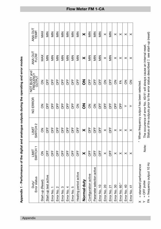
Flow Meter FM 1-CA
Appendix
MA
X
MIN
MIN
MIN
MIN
MIN
MIN
MIN X MIN
MIN
MIN X
MIN X X X X
ON
OFF
OFF
OFF
OFF
OFF
OFF
OFF
ON
OFF
OFF
OFF ON
OFF ON
FA ON
ON
ON
OFF
OFF
OFF
OFF
OFF
OFF ON
ON
ON
ON
OFF
OFF
OFF
OFF
OFF Y Y
Sta
rt-u
p (R
eset
)
Sta
rt-u
p t
est
activ
e
Err
or N
o. 1
Err
or N
o. 2
Err
or N
o. 3
Err
or N
o. 4
Err
or N
o. 5
Hea
ting
per
iod
act
ive
No
rmal
dut
yC
onfig
urat
ion
activ
e
Par
amet
er s
elec
tion
activ
e
Err
or N
o. 1
0
Err
or N
o. 2
0
Err
or N
o. 2
1
Err
or N
o. 3
0
Err
or N
o. 6
0 *
Err
or N
o. 4
0
Err
or N
o. 4
1
Ap
pen
dix
1 -
Per
form
ance
of
the
dig
ital
and
ana
log
ue o
utp
uts
dur
ing
the
op
erat
ing
and
err
or
mo
des
Dut
y/E
rror
sta
tus
LIM
ITS
WIT
CH
1LI
MIT
SW
ITC
H 2
NO
ER
RO
RN
OT
BU
SY
and
FREQ
UEN
CY
OU
TPU
TA
NA
OU
TFL
OW
AN
A O
UT
TEM
P.
ON
OFF
OFF
OFF
OFF
OFF
OFF
OFF X OFF
OFF
OFF X
OFF X X X X
MA
X
MIN
MIN
MIN
MIN
MIN
MIN
MIN X MIN
MIN
MIN X
MIN X X X X
X=
sta
ndar
d p
erfo
rman
ceY
= O
FF p
ulse
FA=
freq
uenc
y ou
tput
10
Hz
Not
e:Th
e oc
cure
nce
of e
rror
No.
40/
41 w
ill a
lway
s ca
use
an in
tern
al r
eset
.
Sta
tus
of t
he o
utp
uts
prio
r to
the
err
or s
tatu
s d
escr
ibed
→ s
ee s
tart
-up
(res
et)
ON
OFF
OFF
OFF
OFF
OFF
OFF
OFF X OFF
OFF
OFF X
OFF X X X X
* W
hen
freq
uenc
y ou
tput
has
bee
n se
lect
ed.

Flow Meter FM 1-CA
Appendix 2 - Menu structure of the FM1-CA (operator dialog)
Appendix
ZERO SUPP.
M
M
M
M
M
M
M
M
M
M
M
M
M
M
M
M
M
M
M
M
M
M
MM
M
M
M
M
M
CO
NF
IGU
RA
TIO
N M
EN
U
OPERAT. MODE
POWER ON!
and
and
and
DELETEMIN VALUE
HEATING UP
CONFIGURATION
PEAK VALUE MAX
PEAK VALUE MIN
12.5 m/s -13.5°C
MA
IN M
EN
U
END OF CONFIG.?
Config. plausible?ERROR CONFIG.
CONFIG. OK!
or
orno
FLOW UNIT
LIMIT SWITCHES
TEMP. UNIT
DISPLAY SELECT
ANA OUT FLOW
ANA OUT TEMP.
PRESS. RANGE
DELETEtotalized quantity
CELSIUS (°C)FAHRENHEIT (°F)KELVIN (K)
yes
and
and
and
and
and
and
and
and
FS
ZERO
OFFSET
FS
ZERO
OFFSET
return to configuration menu
action
Menues page up page down
select and return to config. menuM
LS1 ON
MEASURING TIME
END OF PARAM?
Param. plausible?
PA
RA
ME
TE
R S
EL
EC
TIO
NM
EN
U
FLOWSCALE
LS2 OFF
LS2 ON
LS 1 OFF
and
and
DELETELAST ERROR
PARAMETERS
ERROR PARAM.
PARAM. OK!
or
orno yes
DELETEMAX VALUE
M
M
LAST ERROR
MIN. FLOW = xx%
and
and
M
M
M
PIPE SIZE
CODE T xxx
M
CODE C xxx
M
SENSOR SELECT
GAS SELECT
M
xx.xx bar / xxx.x PSI
xx.xx bar / meas. Temp.
M
M
and
andM
M
DN25 (1 in)
CODE T xxx
M
CODE C xxx
DN32 (1.1/4 in)DN40 (1.1/2 in)DN50 (2 in)
M
M
TP01 (1/2 in)
CODE T xxx
M
CODE C xxx
TP02 (3/4 in)TP03 (1 in)TP04 (1.1/4 in)TP05 (1.1/2 in)TP06 (2 in)
TYPE CST-11AM1TYPE CSP-11AM1BVTYPE CSP-11AM1TYPE CSF-11AM1TYPE So-No. xxx
ZERO
FS
M
M
M
→TYPE
FREQUENCY OUTPUT?M →yes other → no
M
or
FREQUENCY OUTPUTPULSE/..........(unit)
BARGRAPHLITRE/SECONDLITRE/MINUTEMETRE3/HOURFEET3/SECONDFEET3/MINUTEKILOGRAM/SECONDKILOGRAM/MINUTEKILOGRAM/HOURPOUNDS/SECONDPOUNDS/MINUTEPOUNDS/HOURLITREMETRE3
FEET3
KILOGRAMPOUNDS
M
MM
PERCENT (%)METRE/SEC (m/s)FEET/SEC (FPS)BLANK (no unit)
STANDARD FLOWOPERATING FLOW
1.013 bar / 0.0 °C
MM
M
AIRNITROGENOXYGEN
LS1 → F / LS2 → FLS1 → T / LS2 → FLS1 → F / LS2 → TLS1 → T / LS2 → T
M