Embed Size (px)
Citation preview

The D3 product line has transitioned to the D8 product line.
Please see the D8 Product Class Page or contact us at [email protected] for more information.
DZUS Panex® D3 Quarter-Turn Fasteners--- IMPORTANT INFORMATION ---
1
For additional specifying and ordering information, downloadable CAD files, and 3-D solid models visit: www.southco.com or e-mail: [email protected]
117
Qu
ick Access Fasten
ers
Refer to our Southco 2003 Handbook or visit www.southco.com for expanded product listings
STUD
PANEL
RECEPTACLE
SUPPORT
BODY DIAMETER
STUDPANEL
RECEPTACLE
SUPPORT
DZUS® Panex® D3 Quarter-Turn Fasteners - Introduction
Typical Applications• Off -Highway Vehicles
• Motorcycle Fairings
• Domestic Boiler/Controls
• Air Conditioning Unit Access Panels
• CCTV Camera Covers
• Lighting Luminaries
• Wall Cladding
• Protective Helmets
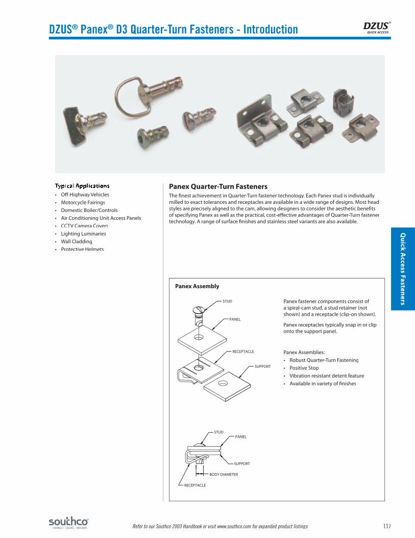
Panex Quarter-Turn FastenersThe fi nest achievement in Quarter-Turn fastener technology. Each Panex stud is individually milled to exact tolerances and receptacles are available in a wide range of designs. Most head styles are precisely aligned to the cam, allowing designers to consider the aesthetic benefi ts of specifying Panex as well as the practical, cost-eff ective advantages of Quarter-Turn fastener technology. A range of surface fi nishes and stainless steel variants are also available.
Panex Assembly
Panex fastener components consist of a spiral-cam stud, a stud retainer (not shown) and a receptacle (clip-on shown).
Panex receptacles typically snap in or clip onto the support panel.
Panex Assemblies:
• Robust Quarter-Turn Fastening
• Positive Stop
• Vibration resistant detent feature
• Available in variety of fi nishes

118
Qu
ick
Acc
ess
Fast
ener
s
Refer to our Southco 2003 Handbook or visit www.southco.com for expanded product listings
StudSize
ReceptacleStyle
ReceptacleStrength1
Max. Total Material Thickness (TMT)2
4mm
Clip-On 30 lbs. 1.5 to 32.4 mmRight Angle Bracket 30 lbs. 1.5 to 32.4 mmFront Load Clip-In 12 lbs. 1.5 to 28.4 mm
Rivet Plate 30 lbs 1.0 to 31.9 mm Weld Plate 30 lbs 1.0 to 31.9 mm
Press-In Insert — 0.7 to 29.6 mmSelf-Clinching Insert — 1.7 to 30.6 mm
6mm
Mini Clip-On 45 lbs. 2.5 to 31.4 mmClip-On 50 lbs. 1.5 to 31.4 mm
Right Angle Bracket 50 lbs. 1.5 to 31.4 mmFront Load Clip-In 18 lbs. 0.8 to 27.7 mm
Rivet Plate 54 lbs. 1.5 to 31.4 mm Weld Plate 54 lbs. 1.5 to 31.4 mm
Press-In Insert — 0.7 to 27.6 mmSelf-Clinching Insert — 1.7 to 28.6 mm
9mm
Clip-On 61 lbs. 2.0 to 28.9 mmRight Angle Bracket 61 lbs. 2.0 to 28.9 mmFront Load Clip-In 23 lbs. 2.5 to 17.4 mm
Rivet Plate 65 lbs. 2.0 to 28.9 mm Weld Plate 65 lbs. 2.0 to 28.9 mm
Panex® Selection Process
Step 1 – Select Receptacle StyleChoice of a Panex receptacle is a balance of load handling requirements and installation method. Select a preferred mounting style from those shown at right. Each style is not available in all sizes, so Step 2 is important.
Step 2 – Select Receptacle SizeUse the Panex Performance Chart to select the receptacle size that best meets your performance requirments.
Step 3 – Select Stud StylePanex studs are shown following the receptacle pages in each size section. Performance is the same for each stud, so selection is based on head style and fi nish. The 6 mm size studs also off er a selection of Partial Ejecting versions. The length of the stud is determined by calculating Total Material Thickness (TMT) as defi ned on the receptacle pages.
Step 4 – Select OptionsIn addition to a choice of stud retainers, Panex studs also off er Head Cup and Retaining Spring options.
NOTE: All Dimensions in metric units. Calculations should be done in metric units.
Receptacle Styles
Clip-On Press-In InsertRight Angle Bracket
Rivet Plate Weld Plate Self-Clinching Insert
Front Load Clip-In
Clip-On – Slip-Onto edge of support panel.
Right Angle Bracket – Used on support panels perpendicular to stud panel.
Front Load Clip-In – Clip-Into a prepared hole anywhere in the support panel (9mm only).
Rivet Plate – Rivet mount onto support panel.
Weld Plate – Rivet mount onto support panel.
Press-In Insert – Suitable for soft metals and thermoplastics. Press or ultrasonic installation.
Self-Clinching Insert – Press-in installation from rear of support panel.
Panex Performance Chart
Notes: 1. Maximum load without distortion.2. See specifi c receptacle page for TMT specifi cation.
DZUS® Panex® D3 Quarter-Turn Fasteners - Introduction
Additional installation information is located at the end of this section.
Installation Guidelines can be found on the DZUS Panex Quarter Turn Installation pages.
All dimensions on this page are in millimeters.

119
Qu
ick Access Fasten
ers
Refer to our Southco 2003 Handbook or visit www.southco.com for expanded product listings
Slotted Wing Bail Phillips Recess Hex Recess
D3-314-1 D3-314-3 D3- 314-4 D3-314-7 D3-314-2
Plastic Steel Retaining Spring
Part No. Part No. H Dim. X Min. X Max. Part No.
D3-324-100-040 D3-324-101-190 48 mm 14 mm 44 mm D3-324-200-200
20 mm 5 mm 16 mm D3-324-201-200
1.3 mm
ø8 mm
ø4.3 mmø5 mm
2 mm
L
1.3 mm
7 mm
ø4.3 mmø5 mm
15.5 mm
L
11 mm12.7 mm1.3 mm
ø4.3 mmø5 mm
2.4 mm
L2 mm
ø8 mm
L
ø4.3 mmø5 mm
#2 3 mm HEX
ø8 mm
ø4.3 mmø5 mm
2 mm
L
0.5 mmø4.3 mm
ø10 mm
0.5 mmø4.3 mm
ø10 mm
ø9 mm
ø0.46 mm
MUST BE SECURED WITH STEEL RETAINER
H
5 mm
DZUS® Panex® D3 Quarter-Turn Stud & Retainer4 mm
Stud Head Styles
Additional Stud DimensionsL Dimension - The stud length (L) depends on the type of receptacle chosen and the thickness of your materials. Use the tables provided with each type of receptacle to determine the proper receptacle size and stud length needed for your application.
Standard Material and FinishesMaterial: Case hardened steel.Finish: Zinc plate and chromate.
Panex Stud Part Numbers
D3-314-1(L)-190Finish – 90 = Zinc Plate with Chromate
91 = Zinc Plate with Black Chromate70 = Bright Chrome
Material (Steel)
Stud Length Number – Determined on Receptacle selection pages
Basic Part No. - From Studs table (above)
Retainers
Standard Material and FinishesPlastic Retainer: High density polyethylene, naturalSteel Retainer: Spring steel, zinc plate and chromateRetaining Spring: Stainless steel
Note:L = Stud Length Number in mm.
All dimensions on this page are in millimeters.

120
Qu
ick
Acc
ess
Fast
ener
s
Refer to our Southco 2003 Handbook or visit www.southco.com for expanded product listings
TMTStud Length No.
(L Dim)1
1.5 to 2.4 mm 082.5 to 3.4 mm 093.5 to 4.4 mm 104.5 to 5.4 mm 115.5 to 6.4 mm 126.5 to 7.4 mm 137.5 to 8.4 mm 148.5 to 9.4 mm 15
9.5 to 10.4 mm 1610.5 to 11.4 mm 1711.5 to 12.4 mm 1812.5 to 13.4 mm 1913.5 to 14.4 mm 2014.5 to 15.4 mm 2115.5 to 16.4 mm 2216.5 to 17.4 mm 2317.5 to 18.4 mm 2418.5 to 19.4 mm 2519.5 to 20.4 mm 2620.5 to 21.4 mm 2721.5 to 22.4 mm 2822.5 to 23.4 mm 2923.5 to 24.4 mm 3024.5 to 25.4 mm 3125.5 to 26.4 mm 3226.5 to 27.4 mm 3327.5 to 28.4 mm 3428.5 to 29.4 mm 3529.5 to 30.4 mm 3630.5 to 31.4 mm 3731.5 to 32.4 mm 38
Part Number D3-334-300-190
Part Number D3-334-310-190
22 mm
12.8 mmTOPVIEW
SIDEVIEW
8 mm
22.5mm
P Q
TMT
TMT = P + Q + Gasket TMT = P + Q + 0.7 mm TMT = P + 1.9 mm
Right Angle Bracket Receptacle
TMT TMT
TMT
PP P
Q
Q
30 mm FRONT VIEW
SIDE VIEW
12 mm
ø3.3 mm2 PLACES18 mm
23.5 mm13.7 mm
18 mm
1.2 mm
DZUS® Panex® D3 Quarter-Turn Receptacle Clip-On, Right Angle Bracket – 4 mm
Example:
TMT = 24 mm. Stud Part Number is D3-314-130-190 for a 4 mm slotted stud.
Clip-On
Material & FinishClip-On Receptacle: Spring steelBracket Receptacle: SteelFinish: Zinc plate and chromate
MechanicalMaximum Load without Distortion: 30 lbs.Maximum Torque: 23 lbs.-in.
To Determine Stud Length Needed1. Calculate the Total Material Thickness (TMT) using Figure 1 below.
2. Then, using the Stud Selection Table, fi nd the TMT Range that applies to your calculated TMT. Use the Stud Length Number to complete the Stud Part Number.
Figure 1: Total Material Thickness (TMT)
Right Angle Bracket
Note:1. Equals (L) Dim on Stud Selection pages.
Additional installation information is located at the end of this section.
All dimensions on this page are in millimeters.

121
Qu
ick Access Fasten
ers
Refer to our Southco 2003 Handbook or visit www.southco.com for expanded product listings
TMT = P + Gasket TMT = P TMT = P + 1.0 mm (Includes Retainer)
TMT TMT TMT
P
P
Q Q P1
XT
TMTStud Length No.
(L Dim)1
1.5 to 2.4 mm 122.5 to 3.4 mm 133.5 to 4.4 mm 144.5 to 5.4 mm 155.5 to 6.4 mm 166.5 to 7.4 mm 177.5 to 8.4 mm 188.5 to 9.4 mm 19
9.5 to 10.4 mm 2010.5 to 11.4 mm 2111.5 to 12.4 mm 2212.5 to 13.4 mm 2313.5 to 14.4 mm 2414.5 to 15.4 mm 2515.5 to 16.4 mm 2616.5 to 17.4 mm 2717.5 to 18.4 mm 2818.5 to 19.4 mm 2919.5 to 20.4 mm 3020.5 to 21.4 mm 3121.5 to 22.4 mm 3222.5 to 23.4 mm 3323.5 to 24.4 mm 3424.5 to 25.4 mm 3525.5 to 26.4 mm 3626.5 to 27.4 mm 3727.5 to 28.4 mm 38
Part Number D3-334-200-190
13.2 mm
9.3 mm
TOPVIEW
SIDEVIEW
11.5 mm
0.5 mm
DZUS® Panex® D3 Quarter-Turn ReceptacleFront Load, Clip-In – 4 mm
Front Load, Clip-In
To Determine Stud Length Needed1. Calculate the Total Material Thickness (TMT) using fi gure 1 below.
2. Then, using the Stud Selection Table, fi nd the TMT Range that applies to your calculated TMT. Use the Stud Length Number to complete the Stud Part Number.
Figure 1: Total Material Thickness (TMT)
Example:
TMT = 24 mm. Stud Part Number is D3-314-134-190 for a 4 mm slotted stud.
Material & FinishMaterial: Spring steelFinish: Zinc plate and chromate
MechanicalMaximum Load without Distortion: 12 lbs.Maximum Torque: 23 lbs.-in.
Note:1. Equals (L) Dim on Stud Selection pages.
Additional installation information is located at the end of this section.
All dimensions on this page are in millimeters.

122
Qu
ick
Acc
ess
Fast
ener
s
Refer to our Southco 2003 Handbook or visit www.southco.com for expanded product listings
TMTStud Length No.
(L Dim)1
1.0 to 1.9 mm 082.0 to 2.9 mm 093.0 to 3.9 mm 104.0 to 4.9 mm 115.0 to 5.9 mm 126.0 to 6.9 mm 137.0 to 7.9 mm 148.0 to 8.9 mm 159.0 to 9.9 mm 16
10.0 to 10.9 mm 1711.0 to 11.9 mm 1812.0 to 12.9 mm 1913.0 to 13.9 mm 2014.0 to 14.9 mm 2115.0 to 15.9 mm 2216.0 to 16.9 mm 2317.0 to 17.9 mm 2418.0 to 18.9 mm 2519.0 to 19.9 mm 2620.0 to 20.9 mm 2721.0 to 21.9 mm 2822.0 to 22.9 mm 2923.0 to 23.9 mm 3024.0 to 24.9 mm 3125.0 to 25.9 mm 3226.0 to 26.9 mm 3327.0 to 27.9 mm 3428.0 to 28.9 mm 3529.0 to 29.9 mm 3630.0 to 30.9 mm 3731.0 to 31.9 mm 38
Part Number D3-334-400-190
20 mm
12 mm18 mm
28 mm
8.3 mm
BOTTOMVIEW
SIDEVIEW
ø3.3 mmTWO PLACES
TMT = P + Q + Gasket TMT = P + Q TMT = P + Q + 0.5 mm (Retainer)
TMT TMT TMT
P
P
P
XT
Q Q Q
DZUS® Panex® D3 Quarter-Turn Receptacle Rivet Plate – 4 mm
Rivet Plate
Material & FinishMaterial: Spring steelFinish: Zinc plate and chromate
MechanicalMaximum Load without Distortion: 30 lbs.Maximum Torque: 23 lbs.-in.
To Determine Stud Length Needed1. Calculate the Total Material Thickness (TMT) using Figure 1 below.
2. Then, using the Stud Selection Table, fi nd the TMT Range that applies to your calculated TMT. Use the Stud Length Number to complete the Stud Part Number.
Figure 1: Total Material Thickness (TMT)
Example:
TMT = 24 mm. Stud Part Number is D3-314-131-190 for a 4 mm slotted stud.
Note:1. Equals (L) Dim on Stud Selection pages.
Additional installation information is located at the end of this section.
All dimensions on this page are in millimeters.

123
Qu
ick Access Fasten
ers
Refer to our Southco 2003 Handbook or visit www.southco.com for expanded product listings
TMTStud Length No.
(L Dim)1
1.0 to 1.9 mm 082.0 to 2.9 mm 093.0 to 3.9 mm 104.0 to 4.9 mm 115.0 to 5.9 mm 126.0 to 6.9 mm 137.0 to 7.9 mm 148.0 to 8.9 mm 159.0 to 9.9 mm 16
10.0 to 10.9 mm 1711.0 to 11.9 mm 1812.0 to 12.9 mm 1913.0 to 13.9 mm 2014.0 to 14.9 mm 2115.0 to 15.9 mm 2216.0 to 16.9 mm 2317.0 to 17.9 mm 2418.0 to 18.9 mm 2519.0 to 19.9 mm 2620.0 to 20.9 mm 2721.0 to 21.9 mm 2822.0 to 22.9 mm 2923.0 to 23.9 mm 3024.0 to 24.9 mm 3125.0 to 25.9 mm 3226.0 to 26.9 mm 3327.0 to 27.9 mm 3428.0 to 28.9 mm 3529.0 to 29.9 mm 3630.0 to 30.9 mm 3731.0 to 31.9 mm 38
Part Number D3-334-500-190
20 mm
28 mm
12 mm18 mm
ø6 mm WELD TABSTWO PLACES
BOTTOMVIEW
SIDEVIEW
8.3 mm
TMT = P + Q + Gasket TMT = P + Q TMT = P + Q + 0.5 mm (Retainer)
TMT TMT TMT
Q Q QP
P
P
XT
DZUS® Panex® D3 Quarter-Turn Receptacle Weld Plate – 4 mm
Weld Plate
Material & FinishMaterial: Spring steelFinish: Zinc plate and chromate
MechanicalMaximum Load without Distortion: 30 lbs.Maximum Torque: 23 lbs.-in.
To Determine Stud Length Needed1. Calculate the Total Material Thickness (TMT) using fi gure 1 below.
2. Then, using the Stud Selection Table, fi nd the TMT Range that applies to your calculated TMT. Use the Stud Length Number to complete the Stud Part Number.
Figure 1: Total Material Thickness (TMT)
Example:
TMT = 24 mm. Stud Part Number is D3-314-131-190 for a 4 mm slotted stud.
Note:1. Equals (L) Dim on Stud Selection pages.
Additional installation information is located at the end of this section.
All dimensions on this page are in millimeters.

124
Qu
ick
Acc
ess
Fast
ener
s
Refer to our Southco 2003 Handbook or visit www.southco.com for expanded product listings
TMTStud Length No.
(L Dim)1
0.7 to 1.6 mm 101.7 to 2.6 mm 112.7 to 3.6 mm 123.7 to 4.6 mm 134.7 to 5.6 mm 145.7 to 6.6 mm 156.7 to 7.6 mm 167.7 to 8.6 mm 178.7 to 9.6 mm 18
9.7 to 10.6 mm 1910.7 to 11.6 mm 2011.7 to 12.6 mm 2112.7 to 13.6 mm 2213.7 to 14.6 mm 2314.7 to 15.6 mm 2415.7 to 16.6 mm 2516.7 to 17.6 mm 2617.7 to 18.6 mm 2718.7 to 19.6 mm 2819.7 to 20.6 mm 2920.7 to 21.6 mm 3021.7 to 22.6 mm 3122.7 to 23.6 mm 3223.7 to 24.6 mm 3324.7 to 25.6 mm 3425.7 to 26.6 mm 3526.7 to 27.6 mm 3627.7 to 28.6 mm 3728.7 to 29.6 mm 38
Part Number D3-334-100-300
TOPVIEW
SIDEVIEW13.3 mm
ø12.4 mm
TMT = P + Gasket TMT = P TMT = P + 0.5 mm (Retainer)
TMT TMT TMT
P
PP
XT
DZUS® Panex® D3 Quarter-Turn ReceptacleFront Mount Insert – 4 mm
Front Mount Insert
MaterialBrass and plated steel
MechanicalInstallation Load: 2025 lbs.Maximum Torque: 23 lbs.-in.
To Determine Stud Length Needed1. Calculate the Total Material Thickness (TMT) using Figure 1 below.
2. Then, using the Stud Selection Table, fi nd the TMT Range that applies to your calculated TMT. Use the Stud Length Number to complete the Stud Part Number.
Figure 1: Total Material Thickness (TMT)
Example:
TMT = 24 mm. Stud Part Number is D3-314-133-190 for a 4 mm slotted stud.
Note:1. Equals (L) Dim on Stud Selection pages.
Additional installation information is located at the end of this section.
All dimensions on this page are in millimeters.

125
Qu
ick Access Fasten
ers
Refer to our Southco 2003 Handbook or visit www.southco.com for expanded product listings
TMTStud Length No.
(L Dim)1
1.7 to 2.6 mm 102.7 to 3.6 mm 113.7 to 4.6 mm 124.7 to 5.6 mm 135.7 to 6.6 mm 146.7 to 7.6 mm 157.7 to 8.6 mm 168.7 to 9.6 mm 17
9.7 to 10.6 mm 1810.7 to 11.6 mm 1911.7 to 12.6 mm 2012.7 to 13.6 mm 2113.7 to 14.6 mm 2214.7 to 15.6 mm 2315.7 to 16.6 mm 2416.7 to 17.6 mm 2517.7 to 18.6 mm 2618.7 to 19.6 mm 2719.7 to 20.6 mm 2820.7 to 21.6 mm 2921.7 to 22.6 mm 3022.7 to 23.6 mm 3123.7 to 24.6 mm 3224.7 to 25.6 mm 3325.7 to 26.6 mm 3426.7 to 27.6 mm 3527.7 to 28.6 mm 3628.7 to 29.6 mm 3729.7 to 30.6 mm 38
Part Number D3-334-110-190
ø10.6 mm
ø6.9 mm
13.5 mm
TOPVIEW
SIDEVIEW
TMT = P + Q + Gasket TMT = P + Q TMT = P + Q + 0.5 mm (Retainer)
TMT TMT TMT
Q Q QP
P
P
XT
Self-Clinching Insert
Material & FinishMaterial: SteelFinish: Zinc plate and chromate
MechanicalInstallation Load: 2700 lbs.Maximum Torque: 23 lbs.-in.Minimum Panel Thickness: 1.3 mm
To Determine Stud Length Needed1. Calculate the Total Material Thickness (TMT) using fi gure 1 below.
2. Then, using the Stud Selection Table, fi nd the TMT Range that applies to your calculated TMT. Use the Stud Length Number to complete the Stud Part Number.
Figure 1: Total Material Thickness (TMT)
Example:
TMT = 24 mm. Stud Part Number is D3-314-132-190 for a 4 mm slotted stud.
Note:1. Equals (L) Dim on Stud Selection pages.
DZUS® Panex® D3 Quarter-Turn ReceptacleSelf-Clinching Insert – 4 mm
Additional installation information is located at the end of this section.
All dimensions on this page are in millimeters.
126
Qu
ick
Acc
ess
Fast
ener
s
Refer to our Southco 2003 Handbook or visit www.southco.com for expanded product listings
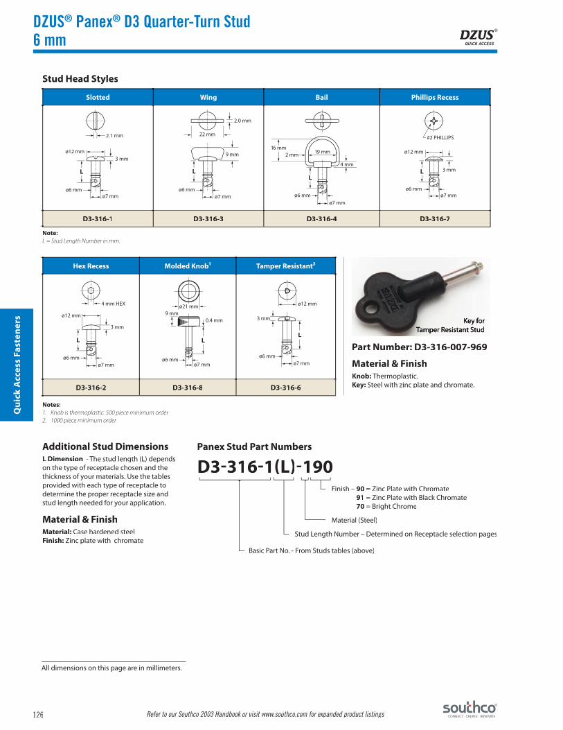
Slotted Wing Bail Phillips Recess
D3-316-1 D3-316-3 D3-316-4 D3-316-7
Hex Recess Molded Knob¹ Tamper Resistant²
D3-316-2 D3-316-8 D3-316-6
2.1 mm
ø12 mm
ø6 mmø7 mm
3 mm
L
2.0 mm
9 mm
ø6 mmø7 mm
22 mm
L
16 mm19 mm2 mm
ø6 mmø7 mm
4 mm
L3 mm
ø12 mm
L
ø6 mmø7 mm
#2 PHILLIPS
4 mm HEX
ø12 mm
ø6 mmø7 mm
3 mm
L
ø21 mm
ø6 mmø7 mm
9 mm0.4 mm
L
ø12 mm
3 mm
L
ø6 mmø7 mm
DZUS® Panex® D3 Quarter-Turn Stud6 mm
Stud Head Styles
Additional Stud DimensionsL Dimension - The stud length (L) depends on the type of receptacle chosen and the thickness of your materials. Use the tables provided with each type of receptacle to determine the proper receptacle size and stud length needed for your application.
Material & FinishMaterial: Case hardened steelFinish: Zinc plate with chromate
Panex Stud Part Numbers
D3-316-1(L)-190Finish – 90 = Zinc Plate with Chromate
91 = Zinc Plate with Black Chromate70 = Bright Chrome
Material (Steel)
Stud Length Number – Determined on Receptacle selection pages
Basic Part No. - From Studs tables (above)
Key forTamper Resistant Stud
Part Number: D3-316-007-969
Material & FinishKnob: Thermoplastic.Key: Steel with zinc plate and chromate.
Note:L = Stud Length Number in mm.
Notes:1. Knob is thermoplastic. 500 piece minimum order.2. 1000 piece minimum order.
All dimensions on this page are in millimeters.

127
Qu
ick Access Fasten
ers
Refer to our Southco 2003 Handbook or visit www.southco.com for expanded product listings
Slotted Wing Hex Recess
D3-376-1 D3-376-3 D3-376-2
LL-5
ø14 mm
L-5 L
ø14 mm
LL-5
ø14 mm
2 mm
20 mm MAX.
20 mm MAX.
9 mm
10 mm
COUNTERBOREø14 mm
Partial Ejecting Stud Head Styles
Partial Ejecting Stud Selection1. Partial Ejecting Studs are supplied as assemblies.
2. Using the TMT dimension tables on the 6 mm receptacle pages, calculate the TMT and add 2.0 mm.
3. Find the applicable range that applies to your calculated TMT and the Stud Length Number stated to the right of the applicable range.
4. Insert the Stud Length Number into the Stud Assembly Part Number. See sample part number below. Ring and Knob heads are not available as partial ejecting.
5. Check that when ejected, the space for the cup and spring does not exceed 20 mm. (See Figure A)
DZUS® Panex® D3 Quarter-Turn StudPartial Ejecting – 6 mm
Panex Stud Part Numbers
D3-376-1(L)-190Finish – 90 = Zinc Plate with Chromate
91 = Zinc Plate with Black Chromate70 = Bright Chrome
Material (Steel)
Stud Length Number – Determined on Receptacle selection pages.Add 2mm to TMT for partial ejecting stud assembly
Basic Part No. - From Studs table (above)
Slotted – Partial Ejecting
Wing – Partial Ejecting
Hex – Partial Ejecting
Additional Stud DimensionsL Dimension - The stud length (L) depends on the type of receptacle chosen and the thickness of your materials. Use the tables provided with each type of receptacle to determine the stud length needed for your application.
Material & FinishStud: Case hardened steel.Cup: Black thermoplastic.Finish: Zinc plate and chromate.
Note:L = Stud Length Number in mm.
Figure A
All dimensions on this page are in millimeters.

128
Qu
ick
Acc
ess
Fast
ener
s
Refer to our Southco 2003 Handbook or visit www.southco.com for expanded product listings
Plastic¹ Steel Retaining Spring
Part No. Part No. H Dim. X Min. X Max. Part No.
D3-326-100-040 D3-326-101-190 48 mm 19 mm 44 mm D3-326-200-200
25 mm 5 mm 21 mm D3-326-201-200
Embellisher Part Number: D3-376-001-049
0.5 mmø6.3 mm
ø12.5 mm
0.5 mmø6.3 mm
ø12.5 mm
ø12 mm
ø0.5 mm
MUST BE SECURED WITH STEEL RETAINER
H
ø14 mm4 mm
1 mm
3.3 mm
DZUS® Panex® D3 Head Embellisher & Retainer6mm
Retainers
Material & FinishPlastic Retainer: High density polyethylene, naturalSteel Retainer: Spring steel, zinc plate and chromateRetaining Spring: Stainless steel
Stud Head Embellisher
Material: Black thermoplastic.
Embellisher Stud Selection1. Cups should be ordered as separate
components.
2. Using the TMT dimension tables on the 6mm receptacle pages, calculate the TMT and add 1.0 mm.
3. Find the applicable range that applies to your calculated TMT and the Stud Length Number stated to the right of the applicable range.
4. Insert the Stud Length Number into the Stud Assembly Part Number. See sample part number below. Stud embellisher is not for use with ring, wing or knob head styles.
Note:1. Not to be used on Molded Knob studs, part number
D3-316-8XX-XXX.
Note: Embellisher only available for tool recess head styles (slotted, Phillips, Hex, Tamper resistant).
All dimensions on this page are in millimeters.

129
Qu
ick Access Fasten
ers
Refer to our Southco 2003 Handbook or visit www.southco.com for expanded product listings
Part Number D3-336-330-130*
TMTStud Length No.
(L Dim)1
2.5 to 3.4 mm 103.5 to 4.4 mm 114.5 to 5.4 mm 125.5 to 6.4 mm 136.5 to 7.4 mm 147.5 to 8.4 mm 158.5 to 9.4 mm 16
9.5 to 10.4 mm 1710.5 to 11.4 mm 1811.5 to 12.4 mm 1912.5 to 13.4 mm 2013.5 to 14.4 mm 2114.5 to 15.4 mm 2215.5 to 16.4 mm 2316.5 to 17.4 mm 2417.5 to 18.4 mm 2518.5 to 19.4 mm 2619.5 to 20.4 mm 2720.5 to 21.4 mm 2821.5 to 22.4 mm 2922.5 to 23.4 mm 3023.5 to 24.4 mm 3124.5 to 25.4 mm 3225.5 to 26.4 mm 3326.5 to 27.4 mm 3427.5 to 28.4 mm 3528.5 to 29.4 mm 3629.5 to 30.4 mm 3730.5 to 31.4 mm 38
24.0 mm
BOTTOMVIEW
SIDEVIEW
8.6 mm
8 mm
12.3 mm
8.8 mm
TMT = P + Q + Gasket TMT = P + Q + 0.7 mm TMT = P + Q + 0.7 mm (Includes Retainer)
TMT TMT TMT
Q Q QP
PP
DZUS® Panex® D3 Quarter-Turn ReceptacleMini Clip-On – 6 mm
Mini Clip-On
* For minimum orders of 10,000 pieces
Material & FinishMaterial: Spring steelFinish: Organic silver
MechanicalMaximum Load without Distortion: 45 lbs.Maximum Torque: 31 lbs.-in.
To Determine Stud Length Needed1. Calculate the Total Material Thickness (TMT) using Figure 1 below.
2. Then, using the Stud Selection Table, fi nd the TMT Range that applies to your calculated TMT. Use the Stud Length Number to complete the Stud Part Number.
Example:
TMT = 24 mm. Stud Part Number is D3-316-131-190 for a 6 mm slotted stud.
Figure 1: Total Material Thickness (TMT)
Note:1. Equals (L) Dim on Stud Selection pages.
Additional installation information is located at the end of this section.
All dimensions on this page are in millimeters.

130
Qu
ick
Acc
ess
Fast
ener
s
Refer to our Southco 2003 Handbook or visit www.southco.com for expanded product listings
Part Number D3-336-300-190
Part Number D3-336-310-190
TMTStud Length No.
(L Dim)1
1.5 to 2.4 mm 092.5 to 3.4 mm 103.5 to 4.4 mm 114.5 to 5.4 mm 125.5 to 6.4 mm 136.5 to 7.4 mm 147.5 to 8.4 mm 158.5 to 9.4 mm 16
9.5 to 10.4 mm 1710.5 to 11.4 mm 1811.5 to 12.4 mm 1912.5 to 13.4 mm 2013.5 to 14.4 mm 2114.5 to 15.4 mm 2215.5 to 16.4 mm 2316.5 to 17.4 mm 2417.5 to 18.4 mm 2518.5 to 19.4 mm 2619.5 to 20.4 mm 2720.5 to 21.4 mm 2821.5 to 22.4 mm 2922.5 to 23.4 mm 3023.5 to 24.4 mm 3124.5 to 25.4 mm 3225.5 to 26.4 mm 3326.5 to 27.4 mm 3427.5 to 28.4 mm 3528.5 to 29.4 mm 3629.5 to 30.4 mm 3730.5 to 31.4 mm 38
25 mm
15.8 mmBOTTOMVIEW
SIDEVIEW
9.3 mm
25mm
33 mm FRONT VIEW
SIDE VIEW
14 mm
ø4.2 mm2 PLACES23 mm
26 mm15.2 mm
20 mm
1.2 mm
P Q
TMT
TMT = P + Q + Gasket TMT = P + Q + 0.8 mm TMT = P + 2.0 mm
Right Angle Bracket Receptacle
TMT TMT
TMT
PP P
XT
Q
Q
DZUS® Panex® D3 Quarter-Turn ReceptacleClip-On, Right Angle Bracket – 6 mm
Clip-On
Right Angle Bracket
Material & FinishClip-On Receptacle: Spring steelBracket Receptacle: SteelFinish: Zinc plate and chromate
MechanicalMaximum Load without Distortion: 50 lbs.Maximum Torque: 31 lbs.-in.
To Determine Stud Length Needed1. Calculate the Total Material Thickness (TMT) using Figure 1 below.
2. Then, using the Stud Selection Table, fi nd the TMT Range that applies to your calculated TMT. Use the Stud Length Number to complete the Stud Part Number.
Example:
TMT = 24 mm. Stud Part Number is D3-316-131-190 for a 6 mm slotted stud.
Figure 1: Total Material Thickness (TMT)
Note:1. Equals (L) Dim on Stud Selection pages.
Additional installation information is located at the end of this section.
All dimensions on this page are in millimeters.

131
Qu
ick Access Fasten
ers
Refer to our Southco 2003 Handbook or visit www.southco.com for expanded product listings
TMTStud Length No.
(L Dim)1
0.8 to 1.7 mm 161.8 to 2.7 mm 172.8 to 3.7 mm 183.8 to 4.7 mm 194.8 to 5.7 mm 205.8 to 6.7 mm 216.8 to 7.7 mm 227.8 to 8.7 mm 238.8 to 9.7 mm 24
9.8 to 10.7 mm 2510.8 to 11.7 mm 2611.8 to 12.7 mm 2712.8 to 13.7 mm 2813.8 to 14.7 mm 2914.8 to 15.7 mm 3015.8 to 16.7 mm 3116.8 to 17.7 mm 3217.8 to 18.7 mm 3318.8 to 19.7 mm 3419.8 to 20.7 mm 3520.8 to 21.7 mm 3621.8 to 22.7 mm 3722.8 to 23.7 mm 38
Part Number D3-336-200-190
16.5 mm
13.6 mm
TOPVIEW
SIDEVIEW
16.5 mm
0.5 mm
TMT = P + Gasket TMT = P TMT = P + 0.5 mm (Retainer)
TMT TMT TMT
P
P
Q Q P0.5
XT
Front Load,Clip-In
Material & FinishMaterial: Spring steelFinish: Zinc plate and chromate
MechanicalMaximum Load without Distortion: 18 lbs.Maximum Torque: 31 lbs.-in.
To Determine Stud Length Needed1. Calculate the Total Material Thickness (TMT) using fi gure 1 below.
2. Then, using the Stud Selection Table, fi nd the TMT Range that applies to your calculated TMT. Use the Stud Length Number to complete the Stud Part Number.
Figure 1: Total Material Thickness (TMT)
Example: TMT = 20 mm. Stud Part Number is D3-316-135-190 for a 6 mm slotted stud.
DZUS® Panex® D3 Quarter-Turn Receptacle Front Load, Clip-In – 6 mm
Note:1. Equals (L) Dim on Stud Selection pages.
Additional installation information is located at the end of this section.
All dimensions on this page are in millimeters.
132
Qu
ick
Acc
ess
Fast
ener
s
Refer to our Southco 2003 Handbook or visit www.southco.com for expanded product listings
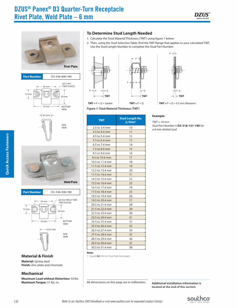
Part Number D3-336-400-190
Part Number D3-336-500-190
TMTStud Length No.
(L Dim)1
2.5 to 3.4 mm 103.5 to 4.4 mm 114.5 to 5.4 mm 125.5 to 6.4 mm 136.5 to 7.4 mm 147.5 to 8.4 mm 158.5 to 9.4 mm 16
9.5 to 10.4 mm 1710.5 to 11.4 mm 1811.5 to 12.4 mm 1912.5 to 13.4 mm 2013.5 to 14.4 mm 2114.5 to 15.4 mm 2215.5 to 16.4 mm 2316.5 to 17.4 mm 2417.5 to 18.4 mm 2518.5 to 19.4 mm 2619.5 to 20.4 mm 2720.5 to 21.4 mm 2821.5 to 22.4 mm 2922.5 to 23.4 mm 3023.5 to 24.4 mm 3124.5 to 25.4 mm 3225.5 to 26.4 mm 3326.5 to 27.4 mm 3427.5 to 28.4 mm 3528.5 to 29.4 mm 3629.5 to 30.4 mm 3730.5 to 31.4 mm 38
25 mm
12 mm20 mm
33 mm
8.5 mm
BOTTOMVIEW
SIDEVIEW
ø3.3 mmTWO PLACES
25 mm
33 mm
12 mm20 mm
ø6 mm WELD TABSTWO PLACES
BOTTOMVIEW
SIDEVIEW
8.5 mm
TMT = P + Q + Gasket TMT = P + Q TMT = P + Q + 0.5 mm (Retainer)
TMT TMT TMT
P
P
P
XT
Q Q Q
DZUS® Panex® D3 Quarter-Turn ReceptacleRivet Plate, Weld Plate – 6 mm
Rivet Plate
Material & FinishMaterial: Spring steelFinish: Zinc plate and chromate
MechanicalMaximum Load without Distortion: 54 lbs.Maximum Torque: 31 lbs.-in.
Weld Plate
To Determine Stud Length Needed1. Calculate the Total Material Thickness (TMT) using fi gure 1 below.
2. Then, using the Stud Selection Table, fi nd the TMT Range that applies to your calculated TMT. Use the Stud Length Number to complete the Stud Part Number.
Figure 1: Total Material Thickness (TMT)
Example:
TMT = 24 mm. Stud Part Number is D3-316-131-190 for a 6 mm slotted stud.
Note:1. Equals (L) Dim on Stud Selection pages.
Additional installation information is located at the end of this section.
All dimensions on this page are in millimeters.

133
Qu
ick Access Fasten
ers
Refer to our Southco 2003 Handbook or visit www.southco.com for expanded product listings
TMTStud Length No.
(L Dim)1
0.7 to 1.6 mm 121.7 to 2.6 mm 132.7 to 3.6 mm 143.7 to 4.6 mm 154.7 to 5.6 mm 165.7 to 6.6 mm 176.7 to 7.6 mm 187.7 to 8.6 mm 198.7 to 9.6 mm 20
9.7 to 10.6 mm 2110.7 to 11.6 mm 2211.7 to 12.6 mm 2312.7 to 13.6 mm 2413.7 to 14.6 mm 2514.7 to 15.6 mm 2615.7 to 16.6 mm 2716.7 to 17.6 mm 2817.7 to 18.6 mm 2918.7 to 19.6 mm 3019.7 to 20.6 mm 3120.7 to 21.6 mm 3221.7 to 22.6 mm 3322.7 to 23.6 mm 3423.7 to 24.6 mm 3524.7 to 25.6 mm 3625.7 to 26.6 mm 3726.7 to 27.6 mm 38
Part Number D3-336-100-300
TOPVIEW
SIDEVIEW16 mm
ø15.5 mm
TMT = P + Gasket TMT = P TMT = P + 0.5 mm (Retainer)
TMT TMT TMT
P
PP
XTPress-In Insert
MaterialBrass and plated steel
MechanicalInstallation Load: 2250 lbs.Maximum Torque: 31 lbs.-in.
To Determine Stud Length Needed1. Calculate the Total Material Thickness (TMT) using Figure 1 below.
2. Then, using the Stud Selection Table, fi nd the TMT Range that applies to your calculated TMT. Use the Stud Length Number to complete the Stud Part Number.
Figure 1: Total Material Thickness (TMT)
Example:
TMT = 24 mm. Stud Part Number is D3-316-135-190 for a 6 mm slotted stud.
DZUS® Panex® D3 Quarter-Turn ReceptaclePress-In Insert – 6 mm
Note:1. Equals (L) Dim on Stud Selection pages.
Additional installation information is located at the end of this section.
All dimensions on this page are in millimeters.

134
Qu
ick
Acc
ess
Fast
ener
s
Refer to our Southco 2003 Handbook or visit www.southco.com for expanded product listings
Part Number D3-336-110-190
TMTStud Length No.
(L Dim)1
1.7 to 2.6 mm 122.7 to 3.6 mm 133.7 to 4.6 mm 144.7 to 5.6 mm 155.7 to 6.6 mm 166.7 to 7.6 mm 177.7 to 8.6 mm 188.7 to 9.6 mm 19
9.7 to 10.6 mm 2010.7 to 11.6 mm 2111.7 to 12.6 mm 2212.7 to 13.6 mm 2313.7 to 14.6 mm 2414.7 to 15.6 mm 2515.7 to 16.6 mm 2616.7 to 17.6 mm 2717.7 to 18.6 mm 2818.7 to 19.6 mm 2919.7 to 20.6 mm 3020.7 to 21.6 mm 3121.7 to 22.6 mm 3222.7 to 23.6 mm 3323.7 to 24.6 mm 3424.7 to 25.6 mm 3525.7 to 26.6 mm 3626.7 to 27.6 mm 3727.7 to 28.6 mm 38
ø13.5 mm
ø9.9 mm
16.3 mm
TOPVIEW
SIDEVIEW
TMT = P + Q + Gasket TMT = P + Q TMT = P + Q + 0.5 mm (Retainer)
TMT TMT TMT
Q Q QP
P
P
XT
DZUS® Panex® D3 Quarter-Turn ReceptacleSelf-Clinching Insert – 6 mm
Self-ClinchingInsert
Material & FinishMaterial: SteelFinish: Zinc plate and chromate
MechanicalInstallation Load: 2700 lbs.Maximum Torque: 31 lbs.-in.
To Determine Stud Length Needed1. Calculate the Total Material Thickness (TMT) using fi gure 1 below.
2. Then, using the Stud Selection Table, fi nd the TMT Range that applies to your calculated TMT. Use the Stud Length Number to complete the Stud Part Number.
Figure 1: Total Material Thickness (TMT)
Example:
TMT = 24 mm. Stud Part Number is D3-316-134-190 for a 6 mm slotted stud.
Note:1. Equals (L) Dim on Stud Selection pages.
Additional installation information is located at the end of this section.
All dimensions on this page are in millimeters.

135
Qu
ick Access Fasten
ers
Refer to our Southco 2003 Handbook or visit www.southco.com for expanded product listings
Slotted Wing Bail Phillips Recess Hex Recess
D3-319-1 D3-319-3 D3-319-4 D3-319-7 D3-319-2
Plastic Steel Retaining Spring
Part No. Part No. H Dim. X Min. X Max. Part No.
D3-329-100-040 D3-329-101-190 48 mm 7 mm 43 mm D3-329-200-200
2.1 mm
ø18 mm
ø9 mmø10 mm
4.5 mm
L
2.0 mm
11.5 mm
ø9 mmø10 mm
30 mm
L
22.2 mm28.5 mm3 mm
ø9 mmø10 mm
5 mm
L
4.5 mm
ø18 mm
L
ø9 mmø10 mm
#3 5 mm HEX
ø18 mm
ø9 mmø10 mm
4.5 mm
L
1 mmø9.3 mm
ø17 mm
1 mmø9.1 mm
ø17 mm
ø18 mm
ø0.8 mm MUST BE SECURED WITH STEEL RETAINER
H
DZUS® Panex® D3 Quarter-Turn Stud & Retainer9 mm
Stud Head Styles
Panex Stud Part Numbers
D3-319-1(L)-190Finish – 90 = Zinc Plate with Chromate
91 = Zinc Plate with Black Chromate70 = Bright Chrome
Material (Steel)
Stud Length Number – Determined on Receptacle Selection pages
Basic Part No. - From Studs tables (above)
Additional Stud DimensionsL Dimension - The stud length (L) depends on the type of receptacle chosen and the thickness of your materials. Use the tables provided with each type of receptacle to determine the proper receptacle size and stud length needed for your application.
Material & FinishMaterial: Case hardened steelFinish: Zinc plate with chromate
Retainers
Material & FinishPlastic Retainer: High density polyethylene, naturalSteel Retainer: Spring steel, zinc plate and chromateRetaining Spring: Stainless steel
Note:L = Stud Length Number in mm
All dimensions on this page are in millimeters.
136
Qu
ick
Acc
ess
Fast
ener
s
Refer to our Southco 2003 Handbook or visit www.southco.com for expanded product listings
SupportThickness
Ranges
Clip-On Part Numbers
H Dim.
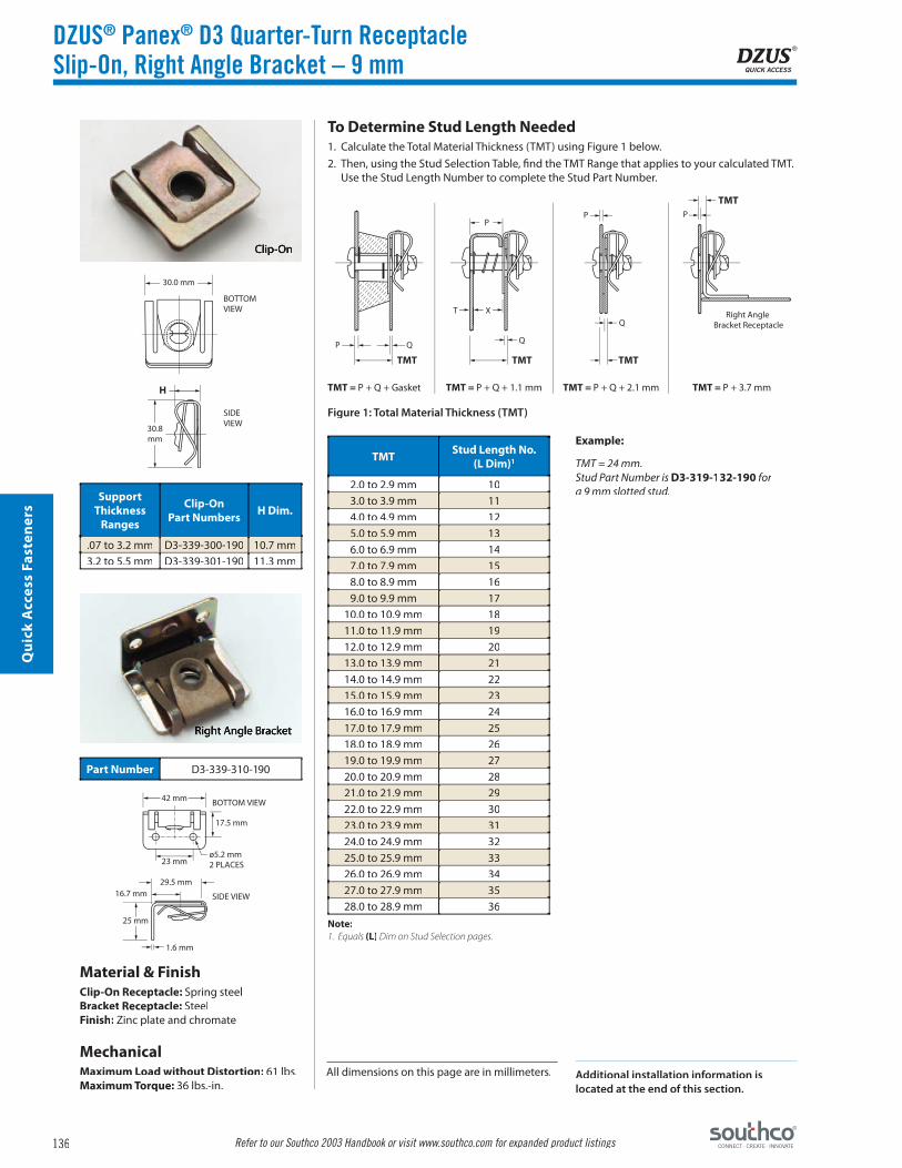
.07 to 3.2 mm D3-339-300-190 10.7 mm3.2 to 5.5 mm D3-339-301-190 11.3 mm
TMTStud Length No.
(L Dim)1
2.0 to 2.9 mm 103.0 to 3.9 mm 114.0 to 4.9 mm 125.0 to 5.9 mm 136.0 to 6.9 mm 147.0 to 7.9 mm 158.0 to 8.9 mm 169.0 to 9.9 mm 17
10.0 to 10.9 mm 1811.0 to 11.9 mm 1912.0 to 12.9 mm 2013.0 to 13.9 mm 2114.0 to 14.9 mm 2215.0 to 15.9 mm 2316.0 to 16.9 mm 2417.0 to 17.9 mm 2518.0 to 18.9 mm 2619.0 to 19.9 mm 2720.0 to 20.9 mm 2821.0 to 21.9 mm 2922.0 to 22.9 mm 3023.0 to 23.9 mm 3124.0 to 24.9 mm 3225.0 to 25.9 mm 3326.0 to 26.9 mm 3427.0 to 27.9 mm 3528.0 to 28.9 mm 36
Part Number D3-339-310-190
30.0 mm
BOTTOMVIEW
SIDEVIEW
H
30.8mm
42 mm BOTTOM VIEW
SIDE VIEW
17.5 mm
ø5.2 mm2 PLACES23 mm
29.5 mm16.7 mm
25 mm
1.6 mm
P Q
TMT
TMT = P + Q + Gasket TMT = P + Q + 1.1 mm TMT = P + Q + 2.1 mm TMT = P + 3.7 mm
Right Angle Bracket Receptacle
TMT TMT
TMT
PP P
XT
Q
Q
DZUS® Panex® D3 Quarter-Turn ReceptacleSlip-On, Right Angle Bracket – 9 mm
Clip-On
Right Angle Bracket
Material & FinishClip-On Receptacle: Spring steelBracket Receptacle: SteelFinish: Zinc plate and chromate
MechanicalMaximum Load without Distortion: 61 lbs.Maximum Torque: 36 lbs.-in.
To Determine Stud Length Needed1. Calculate the Total Material Thickness (TMT) using Figure 1 below.
2. Then, using the Stud Selection Table, fi nd the TMT Range that applies to your calculated TMT. Use the Stud Length Number to complete the Stud Part Number.
Example:
TMT = 24 mm. Stud Part Number is D3-319-132-190 for a 9 mm slotted stud.
Figure 1: Total Material Thickness (TMT)
Note:1. Equals (L) Dim on Stud Selection pages.
Additional installation information is located at the end of this section.
All dimensions on this page are in millimeters.

137
Qu
ick Access Fasten
ers
Refer to our Southco 2003 Handbook or visit www.southco.com for expanded product listings
TMTStud Length No.
(L Dim)1
2.5 to 3.4 mm 223.5 to 4.4 mm 234.5 to 5.4 mm 245.5 to 6.4 mm 256.5 to 7.4 mm 267.5 to 8.4 mm 278.5 to 9.4 mm 28
9.5 to 10.4 mm 2910.5 to 11.4 mm 3011.5 to 12.4 mm 3112.5 to 13.4 mm 3213.5 to 14.4 mm 3314.5 to 15.4 mm 3415.5 to 16.4 mm 3516.5 to 17.4 mm 36
Part Number D3-339-200-190
21 mm
16.6 mm
TOPVIEW
SIDEVIEW
21 mm
0.8 mm
TMT = P + Gasket TMT = P TMT = P + 1.8 mm
TMT TMT TMT
P
P
Q Q P1.8
XT
Front Load, Clip-In
Material & FinishMaterial: Spring steelFinish: Zinc plate and chromate
MechanicalMaximum Load without Distortion: 23 lbs.Maximum Torque: 36 lbs.-in.
To Determine Stud Length Needed1. Calculate the Total Material Thickness (TMT) using fi gure 1 below.
2. Then, using the Stud Selection Table, fi nd the TMT Range that applies to your calculated TMT. Use the Stud Length Number to complete the Stud Part Number.
Figure 1: Total Material Thickness (TMT)
Example:
TMT = 16 mm. Stud Part Number is D3-316-135-190 for a 9 mm slotted stud.
DZUS® Panex® D3 Quarter-Turn ReceptacleFront Load, Clip-In – 9 mm
Note:1. Equals (L) Dim on Stud Selection pages.
Additional installation information is located at the end of this section.
All dimensions on this page are in millimeters.

138
Qu
ick
Acc
ess
Fast
ener
s
Refer to our Southco 2003 Handbook or visit www.southco.com for expanded product listings
Part Number D3-339-400-190
Part Number D3-339-500-190
TMTStud Length No.
(L Dim)1
2.0 to 2.9 mm 103.0 to 3.9 mm 114.0 to 4.9 mm 125.0 to 5.9 mm 136.0 to 6.9 mm 147.0 to 7.9 mm 158.0 to 8.9 mm 169.0 to 9.9 mm 17
10.0 to 10.9 mm 1811.0 to 11.9 mm 1912.0 to 12.9 mm 2013.0 to 13.9 mm 2114.0 to 14.9 mm 2215.0 to 15.9 mm 2316.0 to 16.9 mm 2417.0 to 17.9 mm 2518.0 to 18.9 mm 2619.0 to 19.9 mm 2720.0 to 20.9 mm 2821.0 to 21.9 mm 2922.0 to 22.9 mm 3023.0 to 23.9 mm 3124.0 to 24.9 mm 3225.0 to 25.9 mm 3326.0 to 26.9 mm 3427.0 to 27.9 mm 3528.0 to 28.9 mm 36
30 mm
15.5 mm25 mm
40 mm
10 mm
BOTTOMVIEW
SIDEVIEW
ø3.3 mmTWO PLACES
30 mm
40 mm
15.5 mm25 mm
ø6 mm WELD TABSTWO PLACES
BOTTOMVIEW
SIDEVIEW
10 mm
TMT = P + Q + Gasket TMT = P + Q TMT = P + Q + 1 mm(Includes Retainer)
TMT TMT TMT
P
P
P
XT
Q Q Q
DZUS® Panex® D3 Quarter-Turn Receptacle Rivet Plate, Weld Plate – 9 mm
Rivet Plate
Weld Plate
Material & FinishMaterial: Spring steelFinish: Zinc plate and chromate
MechanicalMaximum Load without Distortion: 65 lbs.Maximum Torque: 36 lbs.-in.
To Determine Stud Length Needed1. Calculate the Total Material Thickness (TMT) using fi gure 1 below.
2. Then, using the Stud Selection Table, fi nd the TMT Range that applies to your calculated TMT. Use the Stud Length Number to complete the Stud Part Number.
Figure 1: Total Material Thickness (TMT)
Example:
TMT = 24 mm. Stud Part Number is D3-319-132-190 for a 9 mm slotted stud.
Note:1. Equals (L) Dim on Stud Selection pages.
Additional installation information is located at the end of this section.
All dimensions on this page are in millimeters.

139
Qu
ick Access Fasten
ers
Refer to our Southco 2003 Handbook or visit www.southco.com for expanded product listings
ReceptacleSize
Support Panel Thickness
Support Panel Cutout (+0.2)
Maximum From Edge (–0.5)
4 0.7 to 2.5 mm 8.0 mm 10.0 mm6 0.7 to 3.2 mm 11.0 mm 11.0 mm
6 mini 0.9 to 2.5 mm 11.0 mm 8.0 mm9 0.7 to 3.2 mm 14.0 mm 13.0 mm9 3.2 to 5.5 mm 14.0 mm 13.0 mm
ReceptacleSize
Support Panel Thickness
Support Panel Cutout Sq. Corner Radius Max.
4 0.7 to 2.5 mm 9.5 to 9.6 mm 0.2 mm6 0.7 to 3.2 mm 14 to 14.2 mm 0.2 mm9 0.7 to 3.2 mm 17 to 17.2 mm 0.2 mm
Receptacle Size Support Panel Cutout A Dimension
4 8.0 mm +0.2 20 mm6 11.0 mm +0.2 25 mm9 14.0 mm +0.2 30 mm
Receptacle SizeA
Dimension Min.B
Dimension Min.Insert Hole Diameter
4 4.5 mm 14 mm 12.0 mm +0.16 5.0 mm 17 mm 15.0 mm +0.1
Receptacle Size Support Panel Cutout
4 8.0 mm +0.26 11.0 mm +0.29 14.0 mm +0.2
Receptacle Size Insert Hole Diameter
4 7.0 mm +0.086 10.0 mm +0.08
SUPPORT PANEL CUTOUT
MAX. FROM EDGE
SUPPORT PANELCUTOUT (SQ.)
RADIUS
DRILL ø3.6 mmAND
COUNTERSINKTO SUIT
A
SUPPORT PANELCUTOUT
SUPPORT PANEL CUTOUT
INSERT HOLEDIAMETER
INSERT HOLEDIAMETER
AB
Clip-On and Right Angle Bracket
Front Load, Clip-In Receptacles
Rivet Plates
Press-In Insert
Weld Plates
Self Clinching Insert
Support Panel Preparation
Support Thickness: 1.3 mm min.Support Material Hardness: RB85 max.
DZUS® Panex® D3 Quarter-Turn Installation
All dimensions on this page are in millimeters.

140
Qu
ick
Acc
ess
Fast
ener
s
Refer to our Southco 2003 Handbook or visit www.southco.com for expanded product listings
ReceptacleSize
Installation ToolPart Number
4 D3-334-119-1906 D3-336-119-190
Standard Panel Hole
Stud Size Stud Hole Diameter(+.2 -.000)
4 mm 5.0 mm
6 mm 7.0 mm
9 mm 10.0 mm
PRESS & TURN INSTALLED POSITION
PRESS
PRESS
INSTALLATIONTOOL
PRESS BED
STUD HOLEDIAMETER
Front Load, Clip-In Receptacles
Press-In Insert
Self-Clinching Insert
Stud Panel Preparation
Insert Receptacles Installation
DZUS® Panex® D3 Quarter-Turn Installation
All dimensions on this page are in millimeters.