Embed Size (px)
Citation preview

D M El-Zeer et al Int. Journal of Engineering Research and Applications www.ijera.com
ISSN : 2248-9622, Vol. 4, Issue 3( Version 1), March 2014, pp.756-769
www.ijera.com 756 | P a g e
Effect of Atmospheric Pressure Glow Discharge Treatment on
Polymerization of Acrylic Fabric and Its Printing Behavior
D M El-Zeer1,2
, A.A. EL-Halwagy3, M.A. EL-Kashouty
3, H.M. Ahmed
3, F.
F.Elakshar2 and A A Garamoon
2
1Taif University , Al-khurma branch ( for girls) , Applied Phys. Dep, Faculty of Science and Education, KSA.
2Center of plasma technology, Al-Azhar University, Nasr City, Cairo, Egypt .
3 Dyening, Printing and Auxiliaries Department, Textile Division, National Research Center, Cair, Egypt.
ABSTRACT Acrylic fibers have been treated by atmospheric pressure glow discharge (APGD) plasma in open air to enhance
surface antistatic properties. The treated surfaces are investigated by scanning electron microscopy (SEM),
Fourier-Transition Infrared Spectroscopy (FTIR) and Atomic Force Microscope (AFM). Plasma treatment of
acrylic fabric has been found to increase the surface roughness, modify the nature and density of surface
functionalities, and drastically improve the wettability and antistatic ability of acrylic fibers.
Keywords: Atmospheric pressure glow discharge, acrylic treatment, printing properties, polymerization.
I. INTRODUCTION
Polyacrylonitrile which are known as acrylic
fibers, have important interest in the textile industry
and is considered as one of leading synthetic fibers.
They are widely used due to a combination of
desirable properties, such as high strength, good
elasticity, mechanical properties as well as excellent
dyeability. Extensive studies have been carried out in
the cationic dyeing of acrylic fabrics (1, 2)
.
Basic dye is by far the most important class of
dye used on acrylic fibers. These dyes dissociate in
water to yield colored cations and are characterized
by their brilliance and its very high tinctorial strength
(3). Basic dyes, which include some of the earliest
synthetic dyes, were originally used for dyeing wool,
silk and mordant cotton, but poor light fastness of
dyeing was obtained until the introduction of acrylic
fibers on which the dyes exhibited higher light
fastness and very good fastness to wet treatments(4)
.
Anionic dyes namely reactive acid and direct
dyes are not usually used for acrylic coloration and it
suffers from being not substantive for the fibers as a
result of the repulsive effect that occur between the
anionic groups present in the fibers and those present
in the dye molecules(5)
. It has been considered that
widening the scope of acrylic coloration using
different classes of dyes which facilitate the technical
production of different colors of the fiber. According
to our knowledge, there is no report as yet appeared
in printing acrylic fibers with conventional anionic
dyes.
These shortcomings might be overcome by
chemical and physical modification of the fiber (6-9)
.
Although chemical modification of the fibers has
been somewhat successful in improving hydrophilic
and antistatic properties, there are environmental
regulations relating to the disposal of chemicals after
treatment (10)
. Plasma treatment, as a clean and
environmental friendly physical technique, opens up
a new possibility in this field. Plasma treatment can
usually induce the processes of generation of polar
groups through post-plasma reaction and also
generation of increased surface roughness via
preferential amorphous structure ablation (11)
.
Different studies on the surface modification
of textile materials by plasma action (11-17)
have been
carried out. On the other hand very little work has
been dealt with the modification of acrylic fibers by
plasma treatment(18-21)
.
In the present paper a comprehensive study
has been carried out on using the APGD plasma in
open air. This study includes employing two types of
techniques:
(I) Acrylic Fabric Treatment with Plasma only This technique includes two methods;
a) Treating the acrylic fabric by plasma .
printing and then followed by the fixation by
steaming.
b) The untreated acrylic fabric has been printed
then it followed by the fixation with plasma.
(II) Acrylic Fabric Treatment with Plasma
followed by hydroxylamine
RESEARCH ARTICLE OPEN ACCESS

D M El-Zeer et al Int. Journal of Engineering Research and Applications www.ijera.com
ISSN : 2248-9622, Vol. 4, Issue 3( Version 1), March 2014, pp.756-769
www.ijera.com 757 | P a g e
Figure 1: Schematic diagram of the discharge cell
used for the treatment of the textile
II. EXPERIMENTAL DETAILS
2.1. Plasma Set up
The experimental setup (Figure 1) is the same as
that in [22] , which consists of two copper plane-
parallel electrodes of 2.5 cm diameter. The two
electrodes were covered with two porous alumina
Al2O3 sheets of 3.5 mm thickness and 4 cm diameter.
The distance between the two dielectric plates was
1.1 mm. A high voltage transformer (1–10 kV),
which generates sinusoidal voltage at a frequency of
50 Hz, was used as an electric power supply to derive
the discharge system. The discharge was operated in
open air under atmospheric pressure. The applied
potential difference (Va) across the electrodes and the
current (I ) passing through the system were recorded
using a digital oscilloscope (HAMEG HM407—40
MHz). The current was measured by the voltage drop
across the resistance R1 (=100 ) connected in series
with the discharge system to the ground as shown in
figure 1. The voltage across the two electrodes was
measured using the potential divider of the resistance
system R2, R3, whereR2/R3 = 500.
2.2. Materials
Acrylic fabrics of 172 g / m2 were supplied from
Misr for spinning and weaving Co., El-Mahalla El-
Kobra, Egypt. The fabric was treated with a solution
containing 2 g / L nonionic detergent and 1g / L
sodium carbonate at a temperature of 45-50 0С for 30
minutes, then thoroughly washed and air dried at
room temperature. Acetic acid, hydroxylamine
hydrochloride, ammonium acetate, urea, ammonium
sulphate and formic acid were laboratory grade
chemicals. Basic dye Red 46 (Ginacryl Red
GRL200%), Reactive dye Bifunction Red 94 were
kindly supplied by Misr Color Co. and Acid dye
Supralan Blue 2R and blue 225 were kindly supplied
by Dystar Co. Commercial sodium alginate of higher
viscosity as nature thickener type was supplied by
Fluka Chemie GmbH CH-9471 Buchs, Myprogum
modified thickener 5% was supplied by ROM
STARoim Co. SETA Print and British gum modified
thickener 4% was used and supplied by Mahalla El-
Kobra, Egypt.
2.3. Experimental procedures
2.3.1. Acrylic Fabric Treatment with Plasma only
Acrylic fabric samples (5x5cm) were placed
between the two electrodes and exposed to low
temperature plasma of air under atmospheric
pressure. This treatment was carried out via two
techniques:
I) The first technique, plasma treatment was
used to activate the acrylic fabric surface before
printing process at discharge power ranges between
0.3 and 2 watts/cm3 and exposure time ranges from
10 to 60 seconds. Then , the plasma treated acrylic
fabrics were printed and followed by the fixation step
using the steamer at a temperature of 105 0C and a
fixing time 15 minutes, then it was washed and air
dried.
II) The second technique, plasma was used not
only for activating the fabric surface but also as a
fixation tool-after printing- instead of using the
steamer. This, two processes were carried out in one
step where, both time and energy could be saved. In
this case, the discharge power and exposure time of
plasma were changed to compensate for the role of
the steamer, where the applied discharge power
ranged from 0.3 to 2.0 watts/cm3
and the exposure
time ranged between 0.5 to 5 minutes. The fabric was
then washed and air dried. Schematic diagram
represents the two techniques is shown as follow;

D M El-Zeer et al Int. Journal of Engineering Research and Applications www.ijera.com
ISSN : 2248-9622, Vol. 4, Issue 3( Version 1), March 2014, pp.756-769
www.ijera.com 758 | P a g e
2.3.2. Treatment with Plasma followed by
hydroxylamine
Acrylic fabric samples (5x5cm) were placed
between two electrodes and exposed to low
temperature air plasma under atmospheric pressure.
Then, the plasma treated samples were put into a
solution of 10 g/l hydroxylamine hydrochloride and
20 g/l ammonium acetate with a liquor ratio 50:1.
This reaction is carried at a temperature of 30 oC for
30 minutes. Then the samples were thoroughly
washed with water and air dried (23).
2.4. Printing methods
a)Printing of plasma treated acrylic fabric
The untreated and plasma treated acrylic
fabrics were printed using the conventional silk
screen printing technique. The printing paste that is
used in the two techniques was the same and was
prepared according to the following recipe:
*The dye used was basic Red 46 (Ginacryl Red
GRL200%).
** Stock thickener was prepared from 40% British
gum which was soaked in boiling water (100 g) and
stirred well to prepare the stock paste. After that, the
basic dye was added and stirring was carried out for
few minutes. Then fixed and washed according to the
following steps:-
- Rinsing with cold water
- Soaping with 1g ∕ l nonionic detergent at 40 0С
- Reduction clear in a solution containing 1-2g ∕ l sodium hydrosulfate,1-2g ∕ l caustic soda and 1-
2g ∕ l nonionic detergent at a temperature 50 0С.
- Rinsing with water at 50 0С.
- Rinsing with cold water and air dried
Finally the samples were air dried and
assessed for different measurements.
b) Printing of acrylic fabrics treated with
plasma and hydroxylamine
The untreated and polymerized plasma LTP
treated samples were printed with reactive and acid
dye, using silk screen printing technique.
These printed samples were thermo-fixed at 190 ◦
C
for 2 minutes.
The printing paste used was prepared according to
the following recipe:
*The reactive dye used was Bifunction Red 94 with
concentration 4% and the acid dye used is Supralan
Blue 2R with concentration 4%.
**Thickener used was either sodium alginate 3% for
reactive dye printing or myprogum 5% for acid dye
printing.
The stock thickener was prepared by soaking
in hot water or cold water for both myprogum and
sodium alginate respectively, and well stirred, then
the dyestuff was added and complete stirring for few
minutes. The samples after printing and fixing were
washed as mentioned before and air dried and
assessed for color strength and fastness properties.
2.5. Measurements and Material Characterization
The treated and the untreated acrylic fabric
samples have been exposed to the following
measurements:
2.5.1. Bulk Properties
The percentage weight loss of the acrylic samples
before and after plasma treatment was measured
according to the weight difference relation (24)
. The
percentage of the moisture regain of acrylic fabric
was determined according to ASTM D2654-89a,
where the moisture regains of the fibers treated by
oven drying method was calculated using the
following formula: Moisture regain %= [ ( Wm – Wd)
/ Wd] x 100 where Wd is the dry weight of fibers and
Wm is the wet weight wet of fibers under 60% relative
humidity for 48 h. The X- Ray crystallinity was
measured with a PW 3710 diffractometer (Phillips)
(XRD) using Cukα radiation at an operating voltage of
40 Kv and a current of 35 mA from 5 to 60 angles.
Pellets were prepared from 0.25gm fiber and
crystalline size was calculated from the equation: t
=kλ / β cos θ Where t = the size of crystal (Å), k =
shape factor (0.94), λ=wave length of x-ray (1.542Å),
β=half-width (radian), θ =Bragg angle.
Dye* 0.7 g
Thickener**
89.2 g
Acetic acid 0.1 g
Boiling water X g
100 g
Dye* 20 G
Urea 50 g
Thickener**
50 g
Ammonium sulphate
solution (50%)
60 g
Formic acid (85%) 10 g
Water X g
1000 g

D M El-Zeer et al Int. Journal of Engineering Research and Applications www.ijera.com
ISSN : 2248-9622, Vol. 4, Issue 3( Version 1), March 2014, pp.756-769
www.ijera.com 759 | P a g e
2.5.2. Surface Morphology and Properties
Changes in fabric whiteness after plasma
exposure were measured with an Elrepho 2000
Reflectance Spectrophotometer (Data Color
International) according to AATCC test method 153-
1985. The wettability was evaluated by measuring
the wetting time according to the AATCC method (25)
. A drop of water is allowed to fall from a fixed
hight onto the surface of the acrylic fabric under
examination. The time that has been taken for the
drop of water to disappear has been measured and
taken as wetting time, and the results were the
average value of four readings. The antistatic
properties of acrylic fabrics were measured using the
system FMX-003 SIMCO electrostatic (SiN:
R001740 Type, made in Japan). Where the FMX-003
is a compact electrostatic field meter used for
location and measuring static charges voltages within
+/− 22 KV. The untreated and plasma treated fabrics
were investigated by a Scanning Electron Microscope
(SEM) JSMT-20, JEOL-Japan, magnification range
1500-2000x, resolution 200A°, and accelerating
voltage 19 kV. Before examinations, the fabric
surface was prepared on an appropriate disk and
coated randomly by a spray of gold. These
investigations were carried out at the department of
physical chemistry ,NRC Egypt. Fourier- transition
infrared spectroscopy (FTIR) was performed using a
Pye-Unicam spectra-1000 machine to determine the
functional groups on the surface of the acrylic
samples. Potassium bromide (KBr) disc was used.
Surface morphology of the treated and untreated
samples was studied by using a wet- SPM9600
Scanning Probe Microscope (Shimadzu Made in
Japan). It uses a probe that has a nanosize tip
mounted on a flexible cantilever. The tip was scanned
slowly across the surface of a specimen. The force
between the atoms on the surface of scanned material
and those on the scan causes the tip to deflect. This
deflection can be recorded by using a laser focused
on the top of the cantilever and reflected onto photo
detectors down to the nanoscales. Atomic force
microscopy provides high resolution images of
surface even if they were nonconducting. In this
study, scanning was carried out in contact mode.
Scanning range was set at a size of 5.0μm x 5.0μm
and scanning frequency is 1.5 Hz. All images were
obtained at ambient conditions immediately after
plasma treatment.
2.5.3. Printing Properties
The color yield (K/S) of each printed sample
was measured using a Data Color SF 600plus
Colorimeter using a measured area with diameter of
9mm. All the (K/S) values were calculated by
subtracting the (K/S) value of the printed untreated
sample from the (K/S) values of the printed treated
samples. (i.e values obtained are relative color
strength). The dye fixation on acrylic was estimated
by extracting equal size (2x2 cm) samples
immediately after printing and drying, and after
fixation and final soaping, in 85% o-phosphoric acid.
The fixation was calculated as follows: Fixation (%)
=[O.Dp/ O.Dw] X 100 Where O.Dw is the optical
density of the just printed and dried sample and O.Dp
is the optical density of the printed and dried sample
subjected to fixation followed by thoroughly rinsing
in cold water and soaping at the boil for 5 minutes.
The dye-fiber reaction indicated by fixation ratio was
estimated by subjecting the printed samples, after
soaping at boil, to extraction with 50% urea solution
and 1 % nonionic wetting agent for 3 minutes at boil
(26). The extent of reaction was calculated by
determining the k/S of the printed samples before and
after extraction using the reflectance values and
Kubelka-Monk function (27)
. The fixation ratio was
calculated by the following formula: Fixation ratio
(%) = [(K/S)E /(K/S)W]X 100 Where (K/S)W is the
Color strength of the printed and dried sample
subjected to fixation followed by thorough rinsing
cold water and soaping at boil for 5 minutes and
(K/S)E is the Above mentioned soaped samples
subjected to extraction with urea solution. Changes in
roughness values were measured for the printed
untreated and treated acrylic samples using a surface
roughness measuring instrument SEM1700α .The
results obtained were the average values of three
readings. The color fastness of the printed fabrics was
assessed by the AATCC Test Method 16-2001(color
fastness to light), AATCC Test Method 61-
2001(color fastness to laundering) and AATCC Test
Method 8-2001(color fastness to rubbing).
III. RESULTS AND DISCUSSION
APGD plasma is considered to be an ideal
technique to enhance the modification of both
physical and chemical properties of acrylic fabric.
Hence the surface is exposed to low temperature
APGD plasma in atmospheric air. In general, plasma
treatment is controlled by several factors such as
discharge power, exposure time, gas type and
pressure ...etc. In our studies, both power and time
are taken in consideration.
3.1. Electrical Characteristics and Power
Measurements
3.1.1. Voltage and current wave forms.
Figures 2(a)–(d) represent the voltage and
current oscillograms of the APGD plasma in air and
different applied voltages where the currents are a)
0.2 mA, b) 0.6mA, c) 1mA, and d) 1.5 mA
respectively.

D M El-Zeer et al Int. Journal of Engineering Research and Applications www.ijera.com
ISSN : 2248-9622, Vol. 4, Issue 3( Version 1), March 2014, pp.756-769
www.ijera.com 760 | P a g e
The APGD plasma is a special type of the
dielectric barrier discharge (DBD) plasma. This
discharge is characterized by the absence of the
micro discharge that are present in the general form
of the DBD and causes the formation of short-lived
microfilaments (28)
. If the glow discharge contains
some microfilaments then it is called a quasiglow
discharge(29).
The APGD is considered to be a very
important technique in textile treatment because of its
homogeneity effect on the textile surface that cause a
uniform treatment without burning it.
Figure 2: Current- voltage waveforms, at the currents are a) 0.2 mA, b) 0.6 mA, c) 1mA, and d) 1.5mA respectively.
Obtaining the APGD by using porous
alumina sheets has been found due to the special
configuration of the alumina sheets, which are
characterized by the existence of micro holes. An
internal discharge takes place inside the micro holes
and on the surface of the porous alumina. This
internal discharge provides seed electrons sufficient
for the initiation and growth of the discharge in the
APGD form inside gas between the two alumina
sheets as it was stated in (30)
. From figure (1a-d) it can
be noticed that the discharge is uniform with a small
component of microfilaments that are superimposed
on the glow component of the APGD .
3.1.2. The consumed power in the APGD
The mean power consumed in the APGD can be
estimated by taking the integration over one cycle of
the product of the I(t) and V(t) waveforms (31)
.
dttVtIdSTp
T
adisch )().(/10
(1)
Where, P : is the power per unit of the discharge
volume, Va : is the applied voltage, Idisch : is the
discharge current, S : is the electrode surface, d : is the
gas gap, and T: is period.
The mean power per cm3 consumed in the APGD
have been calculated at different currents and have been
plotted against these currents as shown in Fig. (3).
Then, it can be easily calculated the mean power
density that consumed in the APGD at different
currents from the same Fig (3).
0.2 0.4 0.6 0.8 1.0 1.2 1.4 1.6 1.8 2.0
0.0
0.5
1.0
1.5
2.0
2.5
3.0
3.5
4.0
Th
e c
on
su
me
d p
ow
er
de
ns
ity
(Wa
tt/C
m3)
The current (mA)
Figure 3: The consumed power density in the APGD
at different currents.
-4
-3
-2
-1
0
1
2
3
4
0 20 40 60 80 100
Time (m sec)
Ap
plie
d v
olt
ag
e (
kV
)
-3
-2
-1
0
1
2
3
Th
e c
urre
nt (m
A)
(b)
-4
-3
-2
-1
0
1
2
3
4
0 20 40 60 80 100
Time (m sec)
Ap
plie
d v
olt
ag
e (
KV
)
-3
-2
-1
0
1
2
3
Th
e c
urre
nt (m
A)
(a)
-4
-3
-2
-1
0
1
2
3
4
0 20 40 60 80 100
Time (m sec)
Ap
plie
d v
olt
ag
e (
kV
)
-3
-2
-1
0
1
2
3
Th
e c
urre
nt (m
A)
-4
-3
-2
-1
0
1
2
3
4
0 20 40 60 80 100
Time (m sec)
Ap
plie
d v
olt
ag
e (
kV
)
-3
-2
-1
0
1
2
3T
he
cu
rren
t (mA
)
(c) (d)
D M El-Zeer et al Int. Journal of Engineering Research and Applications www.ijera.com
ISSN : 2248-9622, Vol. 4, Issue 3( Version 1), March 2014, pp.756-769
www.ijera.com 761 | P a g e
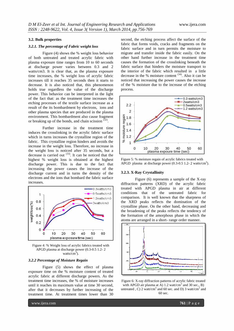
3.2. Bulk properties
3.2.1. The percentage of Fabric weight loss
Figure (4) shows the % weight loss behavior
of both untreated and treated acrylic fabric with
plasma exposure time ranges from 10 to 60 seconds
at discharge power varies between 0.3 and 2
watts/cm3. It is clear that, as the plasma exposure
time increases, the % weight loss of acrylic fabric
increases till it reaches 35 seconds then it starts to
decrease. It is also noticed that, this phenomenon
holds true regardless the value of the discharge
power. This behavior can be interpreted in the light
of the fact that: as the treatment time increases the
etching processes of the textile surface increase as a
result of the its bombardment by electrons, ions and
other plasma species that are produced in the plasma
environment. This bombardment also cause fragment
or breaking up of the bonds, and chain scission (32)
.
Further increase in the treatment time
induces the crosslinking in the acrylic fabric surface
which in turns increases the crystalline region of the
fabric. This crystalline region hinders and avoids the
increase in the weight loss. Therefore, no increase in
the weight loss is noticed after 35 seconds, but a
decrease is carried out (33)
. It can be noticed that the
highest % weight loss is obtained at the highest
discharge power. This is due to the fact that
increasing the power causes the increase of the
discharge current and in turns the density of the
electrons and the ions that bombard the fabric surface
increases.
Figure 4: % Weight loss of acrylic fabrics treated with
APGD plasma at discharge power (0.3-0.5 1.2- 2
watts/cm3).
3.2.2 Percentage of Moisture Regain
Figure (5) shows the effect of plasma
exposure time on the % moisture content of treated
acrylic fabric at different discharge powers. As the
treatment time increases, the % of moisture increases
until it reaches its maximum value at time 30 second,
after that it decreases by further increasing of the
treatment time. At treatment times lower than 30
second, the etching process affect the surface of the
fabric that forms voids, cracks and fragments on the
fabric surface and in turn permits the moisture to
migrate and transfer inside the fabric easily. On the
other hand further increase in the treatment time
causes the formation of the crosslinking beneath the
fabric surface that hinders the moisture transport to
the interior of the fabric which resulted in a little
decrease in the % moisture content (34)
. Also it can be
noticed that increasing the power causes the increase
of the % moisture due to the increase of the etching
process.
Figure 5: % moisture regain of acrylic fabrics treated with
APGD plasma at discharge power (0.3-0.5 1.2- 2 watts/cm3).
3.2.3. X-Ray Crystallinity
Figure (6) represents a sample of the X-ray
diffraction patterns (XRD) of the acrylic fabric
treated with APGD plasma in air at different
conditions that of the untreated fabric for
comparison. It is well known that the sharpness of
the XRD peaks reflects the domination of the
crystalline phase. On the other hand, decreasing and
the broadening of the peaks reflects the tendency of
the formation of the amorphous phase in which the
atoms are arranged in a short- range order manner.
Figure 6: X-ray diffraction patterns of acrylic fabric treated
with APGD air plasma at A) 1.2 watt/cm3 and 30 sec., B)
untreated , C) 2 watt/cm3 and 60 sec. and D) 3 watt/cm3 and
60 sec.
1
1.2
1.4
1.6
1.8
2
2.2
0 10 20 30 40 50 60
% m
ois
ture
re
ga
in
plasma expoure time (sec)
0.3 watts/cm32watts/cm30.5watts/cm31.2 watts/cm3
D M El-Zeer et al Int. Journal of Engineering Research and Applications www.ijera.com
ISSN : 2248-9622, Vol. 4, Issue 3( Version 1), March 2014, pp.756-769
www.ijera.com 762 | P a g e
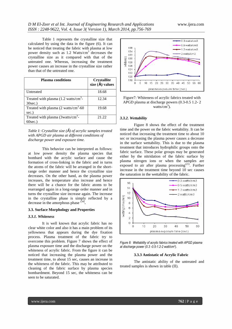
Table 1 represents the crystalline size that
calculated by using the data in the figure (6). It can
be noticed that treating the fabric with plasma at low
power density such as 1.2 Watts/cm3 decreases the
crystalline size as it compared with that of the
untreated one. Whereas, increasing the treatment
power causes an increase in the crystalline size rather
than that of the untreated one.
Plasma conditions Crystallite
size (Ǻ) values
Untreated 18.68
Treated with plasma (1.2 watts/cm3-
30sec.)
12.34
Treated with plasma (2 watts/cm3-60
sec.)
19.68
Treated with plasma (3watts/cm3-
60sec.)
21.22
Table I: Crystallite size (Ǻ) of acrylic samples treated
with APGD air plasma at different conditions of
discharge power and exposure time.
This behavior can be interpreted as follows:
at low power density the plasma species that
bombard with the acrylic surface and cause the
formation of cross-linking in the fabric and in turns
the atoms of the fabric will be arranged in the short-
range order manner and hence the crystalline size
decreases. On the other hand, as the plasma power
increases, the temperature also increase and hence
there will be a chance for the fabric atoms to be
rearranged again in a long-range order manner and in
turns the crystalline size increase again. The increase
in the crystalline phase is simply reflected by a
decrease in the amorphous phase (34)
.
3.3. Surface Morphology and Properties
3.3.1. Whiteness
It is well known that acrylic fabric has no
clear white color and also it has a main problem of its
yellowness that appears during the dye fixation
process. Plasma treatment of the fabric try to
overcome this problem. Figure 7 shows the effect of
plasma exposure time and the discharge power on the
whiteness of acrylic fabric. From the figure it can be
noticed that increasing the plasma power and the
treatment time, to about 15 sec, causes an increase in
the whiteness of the fabric. This may be attributed to
cleaning of the fabric surface by plasma species
bombardment. Beyond 15 sec, the whiteness can be
seen to be saturated.
Figure7: Whiteness of acrylic fabrics treated with
APGD plasma at discharge powers (0.3-0.5 1.2- 2
watts/cm3).
3.3.2. Wettability
Figure 8 shows the effect of the treatment
time and the power on the fabric wettability. It can be
noticed that increasing the treatment time to about 10
sec or increasing the plasma power causes a decrease
in the surface wettability. This is due to the plasma
treatment that introduces hydrophilic groups onto the
fabric surface. These polar groups may be generated
either by the nitridation of the fabric surface by
plasma nitrogen ions or when the samples are
exposed to air after plasma processing(21)
. Further
increase in the treatment time beyond 10 sec causes
the saturation in the wettability of the fabric.
Figure 8: Wettability of acrylic fabrics treated with APGD plasma at discharge power (0.3 -0.5-1.2-2 watt/cm3).
3.3.3 Antistatic of Acrylic Fabric
The antistatic ability of the untreated and
treated samples is shown in table (II).

D M El-Zeer et al Int. Journal of Engineering Research and Applications www.ijera.com
ISSN : 2248-9622, Vol. 4, Issue 3( Version 1), March 2014, pp.756-769
www.ijera.com 763 | P a g e
Table (II) : antistatic ability of the untreated and
plasma-treated samples at discharge power 1.2
watts/cm3.
It can be seen that plasma treatment causes a
sharp increase in the negative static voltage of the
fibers from –1.23 KV for the untreated samples to
about −12 for the treated time of 30 seconds. A
slight decrease in the antistatic ability to (-8 KV) has
been obtained for all the treatment times above 30
sec. It can be stated that plasma treatment of the
acrylic fabric increases the antistatic ability of the
fabric and its surface resistivity.
3.3.4. Scanning Electron Microscope (SEM)
It is well known that, plasma etching causes
drastic changes on the surface structure of the fabric
and gives it other characteristics. Scanning electron
microscope measurement is used to investigate
surface morphology of the fabric. Figure 9 shows
SEM micrographs of the fiber before and after
plasma treatment. It is noticed that the untreated
acrylic fabric has a smooth surface, while in the
treated fabric surface, some voids and cracks are
clearly seen. This photo picture agrees with what is
mentioned before about etching by plasma species
and causes a substantial increase in the surface
roughness and may affect the stiffness of the acrylic
fabric surface(21)
.
Figure 9: SEM images of the untreated and plasma
treated at 1000x(a) untreated acrylic fabric, (b)
plasma treated acrylic fabric under atmospheric
pressure at discharge power 1.2 watts/cm3 for
exposure time 30 seconds.
3.3.5. Atomic Force Microscope (AFM)
The AFM is used to quantify the change in
surface roughness of the treated surface as well as
provide high resolution images showing the
topography. Therefore, it has been used to assess the
topographical and physical changes in structure as a
result of plasma treatment, where, it is by far the
most commonly used for analysis of plasma-treated
textiles. This is due to one of its major benefits of its
ability to image surfaces without the need for any
complicated surface treatment process. Also it is a
technique that can be used in air and imaging can be
also done in water(35).
Based on a relatively simple
concept, the AFM has been partly responsible for the
advancing in nano-revolution in material science (36).
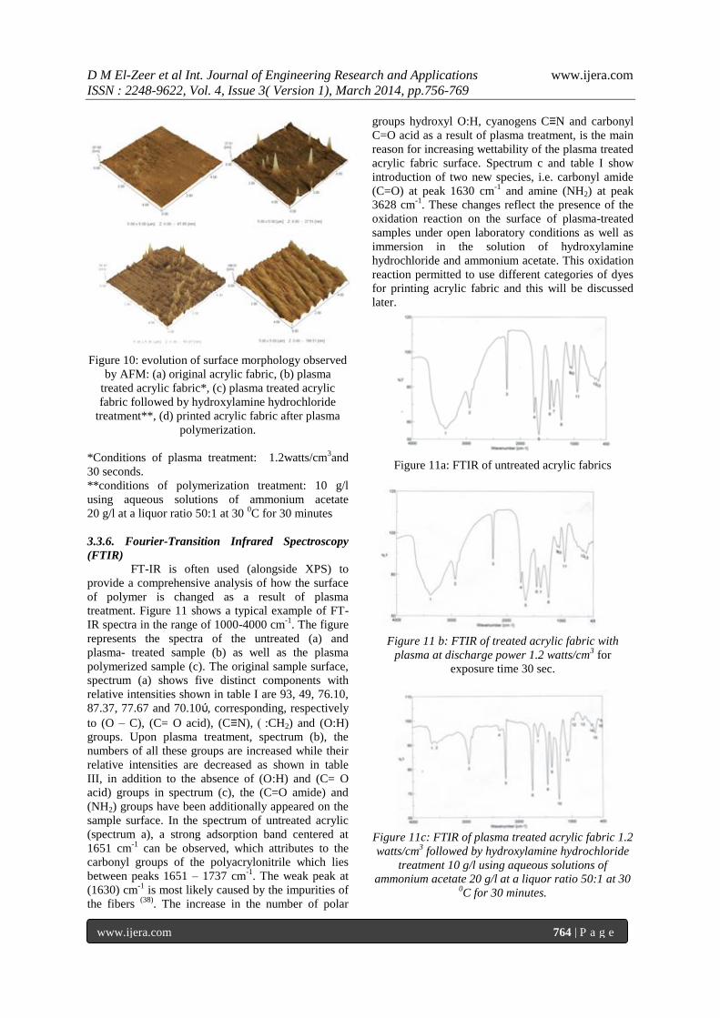
The surface morphology of the acrylic fabrics in the
melt-blown is represented in figure 10. The AFM
image in figure 10 (a) shows the relatively smooth
surface of original fabric, where the microfiber in the
melt blown substrate does not show any fibril
structures on its surface. Plasma activation
significantly changes the surface characteristic of the
fiber as mentioned before. AFM examination, clearly,
reveals the effect of the plasma treatment on the
surface morphology of the fiber and this can be seen
from figure 10 (b). It is clear that, the fabric surface is
obviously roughened after plasma treatment due to its
activation that forms aggregate structures on the
acrylic fabric surface. These aggregates are created
by etching effect of plasma species bombardment (37)
.
Figure 10 (c) shows the surface of plasma treated
acrylic fabric followed by hydroxylamine
hydrochloride treatment- in the presence of
ammonium acetate which causes polymerization for
the plasma treated surface of acrylic fabric. The
admixtures of reactive ammonia with hydroxylamine
into the plasma treated fabric caused strong structure
disorder for the fabric surface.
Thus both etching and deposition take place
and as a result a nano-porous and crosslinked
network with accessible functional groups was
obtained. Besides, the surface roughness has been
increased remarkably compared to plasma treatment
alone, figure 10 (b). Figure 10 (d) shows the surface
of printed acrylic fabric after plasma polymerization.
It is very clear that; the surface roughness is
improved, which may be due to the printing pastes
which filled some of the groves formed due to
etching process. Thus a smooth surface image-nearly
the same as image (a) has been obtained. Thus a great
difference between image in (d) and those in images
(b) and (c) can be noticed.
Sample Antistatic (Kv)
Untreated −1.23
Air plasma−treated
10 sec −5.5
20 sec −8.5
30 sec −12
40 sec −8.5
50 sec −8.3
60 sec −8.0
D M El-Zeer et al Int. Journal of Engineering Research and Applications www.ijera.com
ISSN : 2248-9622, Vol. 4, Issue 3( Version 1), March 2014, pp.756-769
www.ijera.com 764 | P a g e
Figure 10: evolution of surface morphology observed
by AFM: (a) original acrylic fabric, (b) plasma
treated acrylic fabric*, (c) plasma treated acrylic
fabric followed by hydroxylamine hydrochloride
treatment**, (d) printed acrylic fabric after plasma
polymerization.
*Conditions of plasma treatment: 1.2watts/cm3and
30 seconds.
**conditions of polymerization treatment: 10 g/l
using aqueous solutions of ammonium acetate
20 g/l at a liquor ratio 50:1 at 30 0C for 30 minutes
3.3.6. Fourier-Transition Infrared Spectroscopy
(FTIR)
FT-IR is often used (alongside XPS) to
provide a comprehensive analysis of how the surface
of polymer is changed as a result of plasma
treatment. Figure 11 shows a typical example of FT-
IR spectra in the range of 1000-4000 cm-1
. The figure
represents the spectra of the untreated (a) and
plasma- treated sample (b) as well as the plasma
polymerized sample (c). The original sample surface,
spectrum (a) shows five distinct components with
relative intensities shown in table I are 93, 49, 76.10,
87.37, 77.67 and 70.10ύ, corresponding, respectively
to (O – C), (C= O acid), (C≡N), :CH2) and (O:H)
groups. Upon plasma treatment, spectrum (b), the
numbers of all these groups are increased while their
relative intensities are decreased as shown in table
III, in addition to the absence of (O:H) and (C= O
acid) groups in spectrum (c), the (C=O amide) and
(NH2) groups have been additionally appeared on the
sample surface. In the spectrum of untreated acrylic
(spectrum a), a strong adsorption band centered at
1651 cm-1
can be observed, which attributes to the
carbonyl groups of the polyacrylonitrile which lies
between peaks 1651 – 1737 cm-1
. The weak peak at
(1630) cm-1
is most likely caused by the impurities of
the fibers (38)
. The increase in the number of polar
groups hydroxyl O:H, cyanogens C≡N and carbonyl
C=O acid as a result of plasma treatment, is the main
reason for increasing wettability of the plasma treated
acrylic fabric surface. Spectrum c and table I show
introduction of two new species, i.e. carbonyl amide
(C=O) at peak 1630 cm-1
and amine (NH2) at peak
3628 cm-1
. These changes reflect the presence of the
oxidation reaction on the surface of plasma-treated
samples under open laboratory conditions as well as
immersion in the solution of hydroxylamine
hydrochloride and ammonium acetate. This oxidation
reaction permitted to use different categories of dyes
for printing acrylic fabric and this will be discussed
later.
Figure 11a: FTIR of untreated acrylic fabrics
Figure 11 b: FTIR of treated acrylic fabric with
plasma at discharge power 1.2 watts/cm3 for
exposure time 30 sec.
Figure 11c: FTIR of plasma treated acrylic fabric 1.2
watts/cm3 followed by hydroxylamine hydrochloride
treatment 10 g/l using aqueous solutions of
ammonium acetate 20 g/l at a liquor ratio 50:1 at 30 0C for 30 minutes.

D M El-Zeer et al Int. Journal of Engineering Research and Applications www.ijera.com
ISSN : 2248-9622, Vol. 4, Issue 3( Version 1), March 2014, pp.756-769
www.ijera.com 765 | P a g e
It can be also noticed from table III that, in
the case of plasma polymerization, while a
substantial loss in the relative intensities of
cyanogens C≡N and ester groups O:C carried out, a
noticeable change is noticed in the methylene groups
and which increased to 82.05ύ compared to 67.90
and 77.67ύ for untreated and only plasma treated
acrylic fabrics.
Table III: FTIR of acrylic samples treated with air plasma under atmospheric pressure and different conditions
of exposure time and discharge power
3.4 Printing Properties
3.4.1. Color Assessment
I) Treatment of acrylic fabric by using plasma
only
Polyacrylonitrile, or acrylic polymer fiber
containing small amount of anionic centers, such as
sulphonic acid or carboxylic acid groups, can be dyed
or printed with dyes bearing a positive charge, viz,
cationic dyes. The cationic dyes are attracted to the
fabric and then anchored to the fiber by ionic bonds.
Basic dye is -by far- the most important class of dye
used on acrylic fabric where it dissociates in water to
yield colored cations and are characterized by their
brilliance and very high tinctorial strength (4)
.
Figure 12 represents the effect of the plasma
treatment time (in the range of 10 to 60 sec) on the
color strength (K/S) at different plasma power
densities. It can be noticed that the color strength
(K/S) increases with the increase of the treatment
time until it reaches its maximum value in the time
range (20-40 sec) then it decreases again. This
behavior holds true for all power values. It can be
stated that as the treatment time increases the etching
processes increases by the ion bombardment on the
surface and hence it causes the simplicity of the
penetration of the printing paste molecules and
causes the increase in the (K/S). Also the increase in
the (K/S) is attributed to the introduction of polar
groups – due to plasma treatment – which incorporate
with moisture through hydrogen bonding and help
moisture penetration that increases the wettability
and also increases the color strength.
Figure 12: Color strength of acrylic fabrics treated
with APGD plasma at discharge power (0.3-0.5 1.2-
2 watts/cm3).
Further increase in the treatment time provides
some cross-linking that hinder further penetration of
the printing paste into the fabric, therefore the (K/S)
decreases. The highest (K/S) is obtained at power 2.0
watts/cm3 where higher input power causes an
increase in the number of high-speed electron in
plasma and in turns improve plasma treatment
effect,(39)
which leds to the increase of (K/S) value of
fabric (40)
.
II) Treatment of acrylic fabric by using
plasma followed by hydroxylamine
It is well known that anionic dyes namely
reactive and acid dyes are not usually used or even
suitable for acrylic fabric coloration. These dyes
suffer from being not substantive for the fibers as a
result of the repulsive effects that occur between the
anionic groups present in the fiber and those present
in the dye molecules(5)
. This problem could be
overcome by rendering the surface of acrylic fabric
Acrylic state
Relative intensities of selected bands in the FTIR spectra of acrylic samples treated with
plasma
O−H −CH2 C≡N C=O
(acid)
C=O
(amid)
O−C
(ester)
−NH2
Untreated 70.1055 77.6776 87.371 76.10515 − 93.4982 −
Treated with
plasma
55.9621 67.9084 78.4813 65.3341 − 90.4569 −
Polymerization
of treated
plasma
− 82.0515 76.0285 − 71.0058 85.3485 90.5519
20222426283032343638404244
0 5 10 15 20 25 30 35 40 45 50 55 60
colo
r str
ength
(K/S
)
plasma expoure time (sec)
0.3 watts/cm30.5 watts/cm31.2 watts/cm32 watts/cm3
D M El-Zeer et al Int. Journal of Engineering Research and Applications www.ijera.com
ISSN : 2248-9622, Vol. 4, Issue 3( Version 1), March 2014, pp.756-769
www.ijera.com 766 | P a g e
with amino groups – via plasma followed by
hydroxylamine treatment – to enhance its anionic
printability.
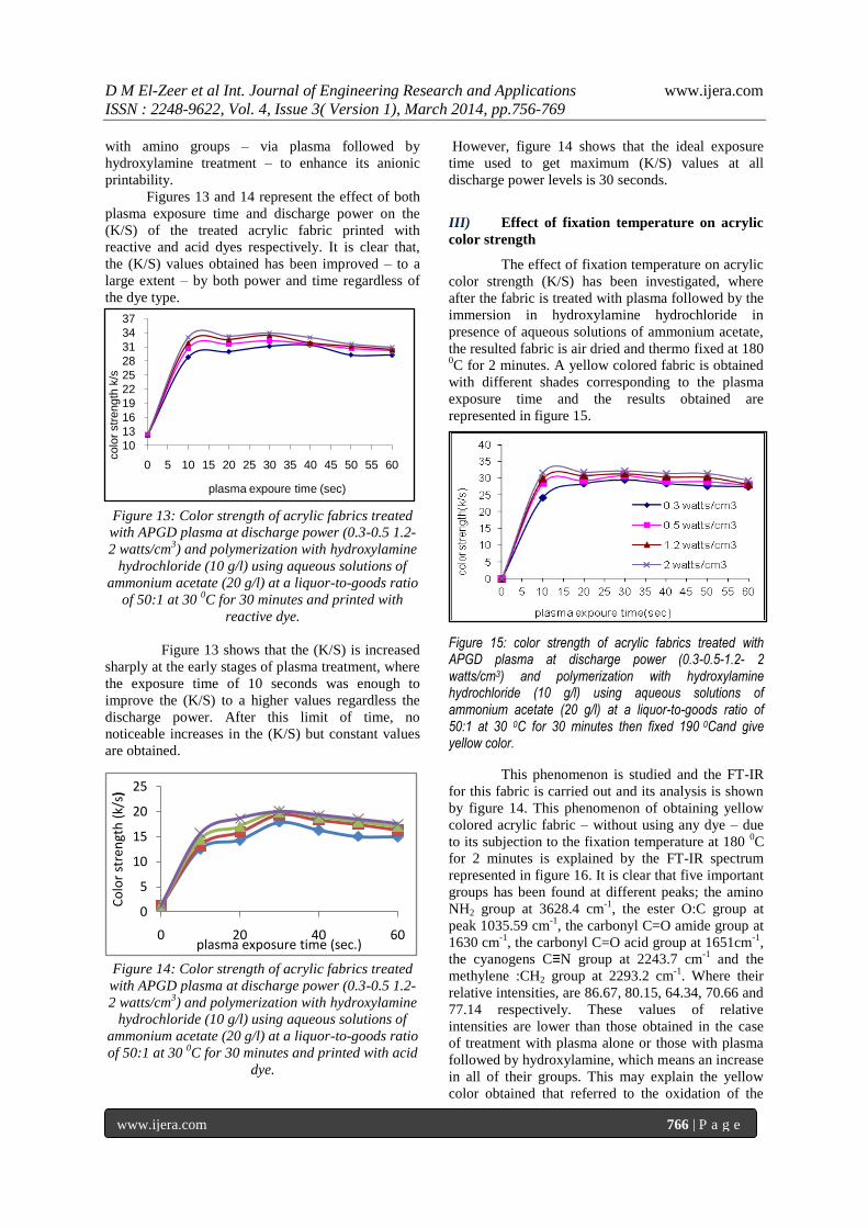
Figures 13 and 14 represent the effect of both
plasma exposure time and discharge power on the
(K/S) of the treated acrylic fabric printed with
reactive and acid dyes respectively. It is clear that,
the (K/S) values obtained has been improved – to a
large extent – by both power and time regardless of
the dye type.
Figure 13: Color strength of acrylic fabrics treated
with APGD plasma at discharge power (0.3-0.5 1.2-
2 watts/cm3) and polymerization with hydroxylamine
hydrochloride (10 g/l) using aqueous solutions of
ammonium acetate (20 g/l) at a liquor-to-goods ratio
of 50:1 at 30 0C for 30 minutes and printed with
reactive dye.
Figure 13 shows that the (K/S) is increased
sharply at the early stages of plasma treatment, where
the exposure time of 10 seconds was enough to
improve the (K/S) to a higher values regardless the
discharge power. After this limit of time, no
noticeable increases in the (K/S) but constant values
are obtained.
Figure 14: Color strength of acrylic fabrics treated
with APGD plasma at discharge power (0.3-0.5 1.2-
2 watts/cm3) and polymerization with hydroxylamine
hydrochloride (10 g/l) using aqueous solutions of
ammonium acetate (20 g/l) at a liquor-to-goods ratio
of 50:1 at 30 0C for 30 minutes and printed with acid
dye.
However, figure 14 shows that the ideal exposure
time used to get maximum (K/S) values at all
discharge power levels is 30 seconds.
III) Effect of fixation temperature on acrylic
color strength
The effect of fixation temperature on acrylic
color strength (K/S) has been investigated, where
after the fabric is treated with plasma followed by the
immersion in hydroxylamine hydrochloride in
presence of aqueous solutions of ammonium acetate,
the resulted fabric is air dried and thermo fixed at 180 0C for 2 minutes. A yellow colored fabric is obtained
with different shades corresponding to the plasma
exposure time and the results obtained are
represented in figure 15.
Figure 15: color strength of acrylic fabrics treated with APGD plasma at discharge power (0.3-0.5-1.2- 2 watts/cm3) and polymerization with hydroxylamine hydrochloride (10 g/l) using aqueous solutions of ammonium acetate (20 g/l) at a liquor-to-goods ratio of 50:1 at 30 0C for 30 minutes then fixed 190 0Cand give yellow color.
This phenomenon is studied and the FT-IR
for this fabric is carried out and its analysis is shown
by figure 14. This phenomenon of obtaining yellow
colored acrylic fabric – without using any dye – due
to its subjection to the fixation temperature at 180 0C
for 2 minutes is explained by the FT-IR spectrum
represented in figure 16. It is clear that five important
groups has been found at different peaks; the amino
NH2 group at 3628.4 cm-1
, the ester O:C group at
peak 1035.59 cm-1
, the carbonyl C=O amide group at
1630 cm-1
, the carbonyl C=O acid group at 1651cm-1
,
the cyanogens C≡N group at 2243.7 cm-1
and the
methylene :CH2 group at 2293.2 cm-1
. Where their
relative intensities, are 86.67, 80.15, 64.34, 70.66 and
77.14 respectively. These values of relative
intensities are lower than those obtained in the case
of treatment with plasma alone or those with plasma
followed by hydroxylamine, which means an increase
in all of their groups. This may explain the yellow
color obtained that referred to the oxidation of the
10
13
16
19
22
25
28
31
34
37
0 5 10 15 20 25 30 35 40 45 50 55 60
colo
r str
ength
k/s
plasma expoure time (sec)
0
5
10
15
20
25
0 20 40 60
Co
lor
stre
ngt
h (
k/s)
plasma exposure time (sec.)

D M El-Zeer et al Int. Journal of Engineering Research and Applications www.ijera.com
ISSN : 2248-9622, Vol. 4, Issue 3( Version 1), March 2014, pp.756-769
www.ijera.com 767 | P a g e
amino groups created after plasma polymerization
and was not present in the untreated fabric. Also, the
carbonyl amide group is created due to plasma
polymerization and also is oxidized by oxygen in the
air plasma giving the yellow color.
Table IV: % fixation and % fixation ratio of basic
dyes on acrylic fabrics by using steam or plasma in
fixation process.
Figure 16: FTIR of acrylic fabrics treated with
APGD plasma at discharge power (1.2 watts/cm3) for
exposure time( 30 second ) and polymerization with
hydroxylamine hydrochloride (10 g/l) using aqueous
solutions of ammonium acetate (20 g/l) at a liquor-
to-goods ratio of 50:1 at 30 0C for 30 minutes then
fixed 190 0Cand give yellow color.
3.4.2 Percentage of Dye Fixation and Fixation
Ratio
Fixation of basic dye on acrylic fabric – as
mentioned before – is carried out via two techniques
and the results obtained are studied. A comparison
between the results of the two techniques are
represented in Table IV.
It can be noticed that, the color strength
values obtained when using plasma as a fixation step
for printed samples are much higher in comparable
with that obtained when using steaming method.
Higher levels of fixation has been observed in the
first case which are in the order of (78.52 - 97.4 %) at
0.5-1.2 Watt/cm3 discharge power densities
compared to the level of (73.97- 92.20 %) obtained in
the case of steaming fixation. This phenomenon
holds true for discharge powers 0.5 & 1.2 watts/cm3
while the opposite is obtained at discharge power 2
watts/cm3. This may be due to the increase in the
crystallinity of acrylic fabric at higher power and this
agrees with other results of color strength, wettibility
and % weight loss. The term ‗fixation ratio‘
expresses the amount of dye bonded to the fabric as a
fraction of the dye present in the printed samples
after soaping. Table IV, also, shows the results of the
fixation ratio (%) for the basic dye fixed by the two
methods. The higher values of fixation ratio obtained
in plasma fixation method indicates that out of the
available dye on the soaped samples maximum
amount of dye was bonded with the fiber.
3.4.3. Stiffness
Table V shows the effect of the air plasma
exposure time and discharge power on the stiffness of
treated printed acrylic fabrics.
Table V: Stiffness of acrylic fabrics treated with glow discharge plasma under atmospheric pressure.
Stiffness values of the untreated and plasma treated acrylic fabrics – at different conditions - for various exposure times (sec). Discharge
power
(watts/cm3) 60 50 40 30 20 10
III II I III II I III II I III II I III II I III II I Different cases
31.47 μm untreated
27.2 29.8 31.1 26.2 29.2 31 25.7 28.5 29.8 24.9 27.3 27.8 27.7 30.3 29.4 29.7 30.9 30.8 0.3
26.3 27.9 29.2 25.5 27.1 28.6 24.6 26.7 27.2 23.7 24.4 26.7 25.2 29 28.6 28.7 30.4 29.6 0.5
26.1 27.6 26.7 24.7 26.1 25.6 23.5 25.4 24.4 22.5 24 22.6 24.4 26.3 27.2 27.6 29.8 28.5 1.2
25.3 26.7 25.6 23.9 25.4 24.9 22.4 24.2 23.5 21.7 23.7 21.5 23.6 25.4 24.9 27 28.2 25.7 2

D M El-Zeer et al Int. Journal of Engineering Research and Applications www.ijera.com
ISSN : 2248-9622, Vol. 4, Issue 3( Version 1), March 2014, pp.756-769
www.ijera.com 768 | P a g e
I-treatment with plasma alone according to the first
technique.
II-treatment with plasma alone according to the
second technique.
III-treatment with plasma followed by
hydroxylamine.
It is clear that, the stiffness values of printed
fabric samples that are treated with plasma in all
cases gives the highest improvement compared to the
untreated fabric. This means that the treated samples
become softer regardless plasma exposure times and
discharge powers.
3.4.4.Fastness properties
Table VI show the color strength (K/S) and
fastness properties of printed acrylic fabric
previously treated with air plasma. Samples untreated
and treated for different intervals of time at various
discharge power levels were investigated. It is
observed clearly that, there is a noticeable
improvement in the color strength values for the
treated samples as compared to the untreated ones, as
mentioned before. The overall fastness results – to
washing, rubbing, perspiration and light – for the
treated acrylic fabric range from very good to
excellent.
Light
fastness
Perspiration fastness Rubbing
fastness
Washing
fastness K/S
Tim
e o
f
trea
tmen
t
(sec
.)
Dis
char
ge
po
wer
(wat
ts/c
m3)
Alkali Acid wet dry St. Alt.
St. Alt. St. Alt.
5-6 4 4 4-5 4-5 4 4 4 4-5 22.7 _
0.3
6 5 5 5 5 4-5 4-5 5 5 31.3 10
6-7 5 5 5 5 5 4-5 5 5 32.8 20
6 5 5 5 5 5 4-5 5 5 34.1 30
6-7 5 5 4-5 4-5 5 5 5 5 36.1 40
6-7 4-5 4-5 4-5 4-5 4-5 4-5 5 5 30.3 50
6 5 5 4-5 4-5 4-5 4-5 5 5 27.4 60
6-7 5 5 5 5 4-5 4-5 5 5 33.0 10
0.5
6-7 5 5 5 5 4-5 4-5 5 5 36.4 20
6-7 5 5 5 5 4-5 4-5 5 5 38.4 30
6 5 5 5 5 4-5 4 5 5 37.6 40
5-6 5 5 5 5 4-5 4 5 5 33.3 50
5-6 5 5 5 5 4-5 4-5 5 5 28.5 60
6-7 5 5 5 5 4-5 4-5 5 5 35.9 10
1.2
6-7 5 5 5 5 4-5 4-5 5 5 34.8 20
6-7 5 5 5 5 4-5 4-5 5 5 34.8 30
5-6 5 5 5 5 4 4 5 5 34.2 40
5-6 5 5 5 5 4-5 4 5 5 33.7 50
5-6 5 5 5 5 4-5 4-5 5 5 30.3 60
6-7 5 5 5 5 4-5 4-5 5 5 31.0 10
2
6-7 5 5 5 5 4-5 4-5 5 5 30.8 20
5-6 5 5 5 5 4-5 4-5 5 5 30.8 30
5-6 5 5 5 5 4-5 4-5 5 5 30.4 40
5 5 5 5 5 4-5 4-5 5 5 30.1 50
5-6 5 5 5 5 4-5 4-5 5 5 28.9 60
Table IV: % fixation and % fixation ratio of basic dyes on acrylic fabrics by using steam or plasma in fixation
process.
D M El-Zeer et al Int. Journal of Engineering Research and Applications www.ijera.com
ISSN : 2248-9622, Vol. 4, Issue 3( Version 1), March 2014, pp.756-769
www.ijera.com 769 | P a g e
IV. Conclusion The APGD plasma treatments of acrylic
fabric causes the activation of acrylic surfaces which
leads to improve the properties of acrylic fabric.
Surface performance of plasma-treated acrylic fabric
has been studied morphologically. The investigation
shows that treatment of acrylic surface with plasma
followed by polymerization with hydroxylamine
hydrochloride produced a modified acrylic fabric
which could be able to be printed with acid and
reactive dye giving higher color strength values and
good fastness properties. Characterization of acrylic
samples after treatment may help in choosing the
optimal conditions of plasma treatment and its
relation with the different properties of the fibers.
Reference
[1] Bird CL& Boston WS (1975). The theory of
Coloration of Textiles. London: Dyers
Company Publications Trust.
[2] Munn DM (1979). The dyeing of synthetic-
polymer and acetate fibers. England: Dyers
Company Publications Trust.
[3] Kamel M.M, Helmy H.M, Mashly H.M&
Kafafy H.H (2010). Ultrasonics
Sonochemistry 17 92-97.
[4] David R& Geoffrey H (1990). The Chemistry
and Application of Dyes, New York and
London, 165-166 (Chapter 5).
[5] Reda M. El-Shishtawy, Nassar S.H.&
Nahed S.E. (2007). Dyes and Pigments 74
215-222.
[6] Hsieh Y.L.& Timm D.(1987). Polym. Mater.
Sci. Eng. 56 323.
[7] Kadash M.M.& Seefried C.G. (1985). Plast.
Eng. 41 45.
[8] Keatsu I.& Yoshida M. (1979). J. Appl.
Polym. Sci. 24 23.
[9] Munro H.S., Polym. Mater. Sci. Eng. 58
(1988) 344.
[10] Li R., Ye L., Mai Y.W., Composites A 28
(1997) 73.
[11] Sarmadi M., Denes F., Text. Chem. Color. 28
(1996) 17.
[12] Lee S.G., Kang T.J., Yoon T.H., J. Polym.
Eng. 18 (1998) 49.
[13] Negulescu I.I., Despa S., Chen J., Collier B.J.,
Text.Res. J. 70 (2000) 1.
[14] Yamada K., Haraguchi T., Kajiyama T., J.
Appl. Polym. Sci. 60 (1996) 1847.
[15] Bhat N.V., Benjamin Y.N., Text. Res. J.69
(1999) 38.
[16] Ryu J., Kawamura H., Wakida T., Lee M.,
Sen-I Gakkaishi 48 (1992) 213.
[17] Boyd R.D., Kenwright A.M., Badyal J. P.,
Briggs S.D., Macromolecules 30 (1997) 5429.
[18] Oktem T.N., Seventekin H., Ayhan, Piskin E.,
Melliand Textil. 82 (2001) 190.
[19] Pane S., Tedesco R., Greger R., J. Ind. Text.
31 (2001) 135.
[20] Tschegolja A.S., Weiman E.J., Beder N.M.,
Mittschenko J. I., Mellinand Textil. Int. Text.
Rep. 9 (1980) 1410.
[21] Yan-Chun Liu, Yan-Xiong, Da-Nian Lu, Appl.
Surf. Sci. 252 (2006) 2960-2966.
[22] 22 Garamoon,A.A., and El-zeer,D.M.,
Plasma Sources Sci. Technol. 18 ,(2009) 3
194–201.
[23] El-Shishtawy R.M., Ahmed NSE., Color
Technol. (2005) ; 121:139 and references cited
therein.
[24] Yoon, J., Mc Cord, M.G., Jae, S., &
Bok,C.,Text.Res.J., 75, 11, 771 (2005).
[25] AATCC, Technical Manual, Test Method, 39,
(1971).
[26] Dohmyo, M., Shimizu, Y., & Kimura, M., J.
Seric. Science, Japan., 54(4), 181-185 (1985).
[27] Garland, C.E., in ‗Color Technology in Textile
Chemistry; Ed. Gultekin Celikiz and K;ueni
G., AATCC, PP 107-112, (1983).
[28] Kogelschatz, U., 2003 Dielectric-barrier
discharges: their history, discharge physics,
and industrial applications, Plasma Chem.
Plasma Processing 23 1–46
[29] Alexandre V., Chirokov, ―Stability of
Atmospheric Pressure Glow Discharges‖, A
Thesis Submitted to the Faculty of Drexel
University, 2005.
[30] Garamoon,A.A., and El-zeer,D.M., Plasma
Sources Sci. Technol. 18 ,(2009) 3 194–201
[31] Gherardi N., Gouda G., Gat E., Ricard A. and
Massines F., Plasma Sources Sci. Technol.,
vol. 9, pp. 340-346, 2000.
[32] Chunying Wang, Chaoxia Wang, Fiber and
Polymers (2010), 11, 2, 223-228.
[33] Chen Y.Y., Lin H., Ren Y., J. Zhejiang Uni.
Sci., 8, (2004), 918.
[34] Bhat N.V., Benjamin Y.N., Textile Res. J., 69,
(1999), 1, 38-42.
[35] Crossley J.A.A., Gibson C.Y., Mapledoram
L.D., Huson M.G., Myhra S., Pham D.K.,
SofieldC.J., Turner P.S., Watson G.S.,
31,(2000), 6, 659-667.
[36] Shishoo, R., ―Plasma technologies for
textiles‖, Woodhead Publishing Limited, USA,
P. 6, 264 (2007).
[37] Qufu W., Yingying W., Xueqian W., Fenglin
H., Shengwei Y., J. Appl. Poly. Sci., 106,
(2007), 1243-1247.
[38] Sun Y.Y., Shao Z.Z., Ma M.H., Hu P., Liu
Y.S., Yu T.Y., J. Appl.Polm. Sci., 65,(1997)
959.
[39] Wang C.X., Qiu Y.P., Surf. Coot. Technol.,
201, (2007), 6273.
[40] J. R. Hollahan and A. T. Bell, "Techniques and
applications of plasma chemistry", A Wiley
Interscience publication, New York, USA,
(1947).