Embed Size (px)
Citation preview
DYWIDAG Prestressing Systems using Bars

ETA Approvals ........................................................................................................... 4
System description .................................................................................................... 5
Prestressing Bars / Technical Data ............................................................................ 6
System overview ........................................................................................................ 7
Overview of anchorages ............................................................................................ 8
Applications ............................................................................................................... 9
Overview of bonded bar tendons ............................................................................. 10
Overview of unbonded and external bar tendons ..................................................... 11
Geometrical characteristics of accessories ............................................................. 12
Installation ............................................................................................................... 13
Stressing and grouting ............................................................................................. 14
Equipment for stressing and grouting ...................................................................... 15
Contents
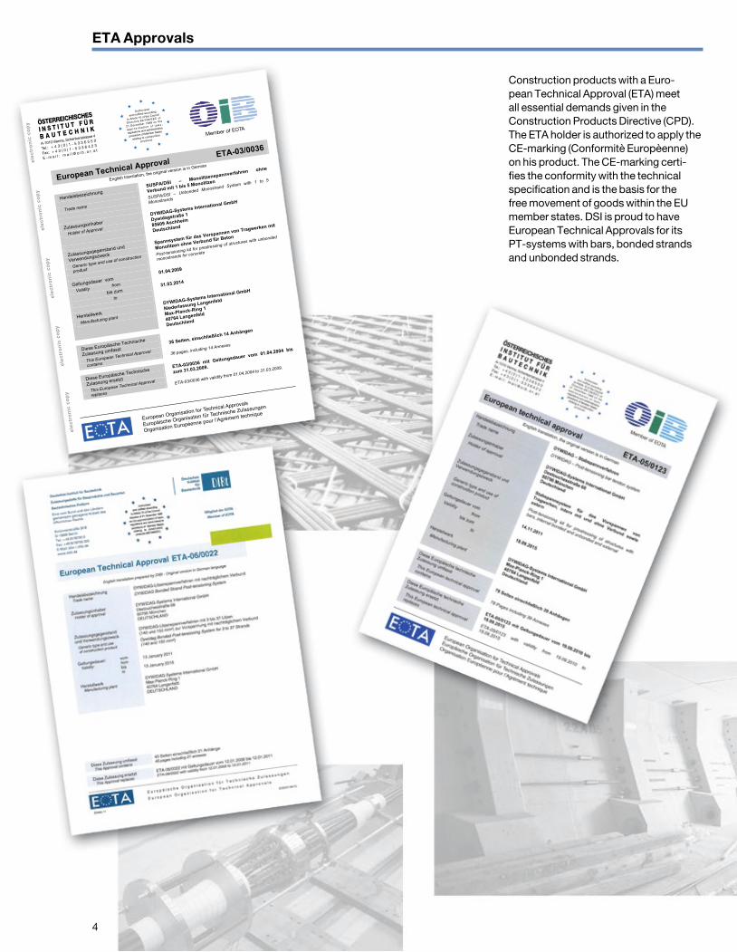
Construction products with a Euro-pean Technical Approval (ETA) meet all essential demands given in the Construction Products Directive (CPD). The ETA holder is authorized to apply the CE-marking (Conformitè Europèenne) on his product. The CE-marking certi-fies the conformity with the technical specifi cation and is the basis for the free movement of goods within the EU member states. DSI is proud to have European Technical Approvals for its PT-systems with bars, bonded strands and unbonded strands.
ETA Approvals
4
ele
ctr
on
ic c
op
ye
lec
tro
nic
co
py
ele
ctr
on
ic c
op
ye
lec
tro
nic
co
py
ele
ctr
on
ic c
op
y ÖSTERREICHISCHES
I N S T I T U T F Ü R
B A U T E C H N I K
A-1010 Vienna, Schenkenstrasse 4
Tel.: + 4 3 ( 0 ) 1 - 5 3 3 6 5 5 0
Fax: + 4 3 ( 0 ) 1 - 5 3 3 6 4 2 3
E - m a i l : m a i l @ o i b . o r . a t
Member of EOTA
★
★
★
★
★
★
★
★ ★
★
★
★
EuropeanOrganisat
ion for Technical App
rovals
Europäische Organ
isation fürTechnisch
e Zulassungen
Organisation Europ
éenne pour l’Agrém
ent technique
Authorised
and notified accordin
g
to Article 10 of the C
ouncil
Directive89/106/E
EC of
21 December 198
8 on the
app rox ima t i on
o f l aws ,
regulations and adm
inistrative
provisionsof Membe
r States
relating toconstructi
on
products
European Technical Approval ETA-03/0036
English translation, the original version is in German
Handelsbezeichnung
SUSPA/DSI – Monolitzenspannverfahren ohne
Verbund mit 1 bis 5 Monolitzen
Trade name
SUSPA/DSI – Unbonded Monostrand System with 1 to 5
Monostrands
Zulassungsinhaber
Holder of Approval
DYWIDAG-Systems International GmbH
Dywidagstraße 1
85609 Aschheim
Deutschland
Zulassungsgegenstand und
Verwendungszweck
Spannsystem für das Vorspannen von Tragwerken mit
Monolitzen ohne Verbund für Beton
Generic type and use of construction
product
Post-tensioning kit for prestressing of structures with unbonded
monostrands for concrete
Geltungsdauer vom
Validity from
01.04.2009
bis zum
to
31.03.2014
Herstellwerk
Manufacturing plant
DYWIDAG-Systems International GmbH
Niederlassung Langenfeld
Max-Planck-Ring 1
40764 Langenfeld
Deutschland
Diese Europäische Technische
Zulassung umfasst
36 Seiten, einschließlich 14 Anhängen
This European Technical Approval
contains
36 pages, including 14 Annexes
Diese Europäische Technische
Zulassung ersetzt
ETA-03/0036 mit Geltungsdauer vom 01.04.2004 bis
zum 31.03.2009.
This European Technical Approval
replaces
ETA-03/0036 with validity from 01.04.2004 to 31.03.2009.

5
DYWIDAG Prestressing Systems are world renowned for reliability and performance, most suitable for all applications in post-tensioned and prestressed constructions. They embrace the whole spectrum from bridge construction, buildings, to civil applications, above and underground.
The first ever structure built with a pro-totype DYWIDAG Post-Tensioning System using bars was the arch-bridge Alsleben (Germany) in 1927. From that time on DYWIDAG has continuously improved its systems to keep up with the growing demand of modern construction technology. In addition to the traditional post-tensioning system using bars, that is mainly geared towards geotechnical applications, building rehabilitation and strengthening, DSI offers a complete product line in strand prestressing (bon-ded, unbonded and external) as well as stay-cables being able to fully serve the post-tensioning construction. DYWIDAG Prestressing Systems have always com-bined highest safety and reliability stan-dards with most economical efficiency in their research and development. Depen-dable corrosion protection methods of the DYWIDAG Prestressing Systems contri-bute to the longevity of modern construc-tion. High fatigue resistance is achieved with optimized material selection and cautious detailing of all the components especially in their system assembly.
The post-tensioning system for the prestressing of structures with bars (inter-nal bonded, unbonded and external ten-dons) is regulated in European Technical Approval ETA-05/0123. This ETA can be downloaded at: https://www.dywidag-systems.com/emea/downloads/dsi-approvals/european-approvals.html
System Description
Ground anchors of up to 47 mm are provided for geotechnical applications. Additionally, DSI USA provides DYWIDAG Prestressing Systems with 65 and 75 mm threadbars.
Internal bar tendons are mainly used in concrete, composite and masonry structures. Internal unbonded and external bar tendons are used for con-crete, composite, steel, timber and masonry structures. Typical applications are transversal prestressing, strengthe-ning of bridges, rehabilitations, connec-tion elements for steel structures and machines and temporary applications.
Uhlavu Bridge, Pilsen, Czech Republic
Typical Coupling, Uhlavu Bridge, Pilsen, Czech Republic
Advantages and Characteristics
n Easy system handling
n Robust design
n Flexible transport length due to couplers
n Also applicable for (very) short tendons due to little slip
n Used in new structures and for strengthening of existing structures
n Suitable as longitudinal or transversal tendons
n Usable as shear reinforcement
n Usable as straight or curved tendons
n Can be used as hangers for concrete or steel arch bridges
n Usable for the temporary or permanent connection of precast
concrete elements
n Many combinations of any structural material are possible
(such as steel with concrete)
n Preassembled unbonded or external tendons with permanent corrosion
protection are available
6
Prestressing Bars and Technical Data
GeneralThe prestressing bars are hot-rolled, tem-pered from the rolling heat, stretched and annealed, with a circular cross section.
The bars are of prestressing steel Y 1050 H according to prEN 10138-4.
The threadbars and plain bars are available in mill length up 18 m and may be cut to specified lengths before shipment to the jobsite.
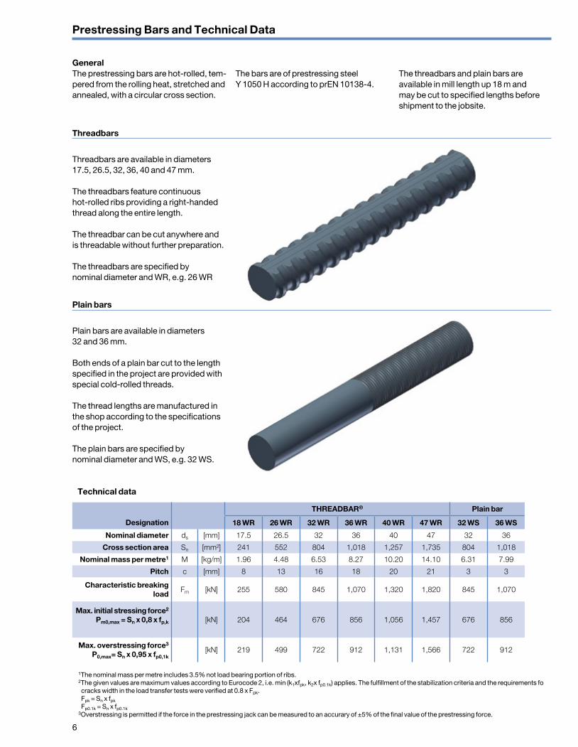
Threadbars
Threadbars are available in diameters 17.5, 26.5, 32, 36, 40 and 47 mm.
The threadbars feature continuous hot-rolled ribs providing a right-handed thread along the entire length.
The threadbar can be cut anywhere and is threadable without further preparation.
The threadbars are specified by nominal diameter and WR, e.g. 26 WR
Plain bars
Plain bars are available in diameters 32 and 36 mm.
Both ends of a plain bar cut to the length specified in the project are provided with special cold-rolled threads.
The thread lengths are manufactured in the shop according to the specifications of the project.
The plain bars are specified by nominal diameter and WS, e.g. 32 WS.
THREADBAR® Plain bar
Designation 18 WR 26 WR 32 WR 36 WR 40 WR 47 WR 32 WS 36 WS
Nominal diameter ds [mm] 17.5 26.5 32 36 40 47 32 36
Cross section area Sn [mm²] 241 552 804 1,018 1,257 1,735 804 1,018
Nominal mass per metre1 M [kg/m] 1.96 4.48 6.53 8.27 10.20 14.10 6.31 7.99
Pitch c [mm] 8 13 16 18 20 21 3 3
Characteristic breaking load
Fm [kN] 255 580 845 1,070 1,320 1,820 845 1,070
Max. initial stressing force2
Pm0,max = Sn x 0,8 x fp,k [kN] 204 464 676 856 1,056 1,457 676 856
Max. overstressing force3 P0,max= Sn x 0,95 x fp0,1k
[kN] 219 499 722 912 1,131 1,566 722 912
1The nominal mass per metre includes 3.5% not load bearing portion of ribs. 2The given values are maximum values according to Eurocode 2, i.e. min (k1xfpk, k2x fp0.1k) applies. The fulfillment of the stabilization criteria and the requirements fo cracks width in the load transfer tests were verified at 0.8 x Fpk. Fpk = Sn x fpk
Fp0.1k = Sn x fp0.1k 3Overstressing is permitted if the force in the prestressing jack can be measured to an accurary of ±5% of the final value of the prestressing force.
Technical data
7
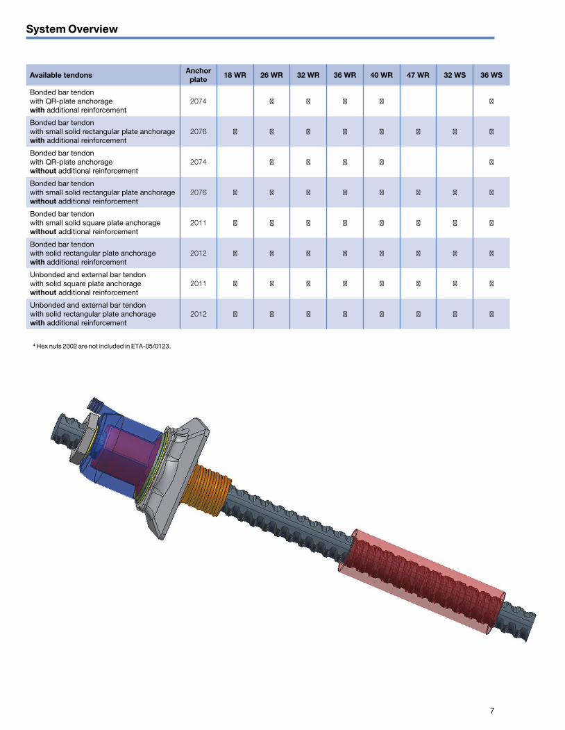
Available tendons Anchor plate 18 WR 26 WR 32 WR 36 WR 40 WR 47 WR 32 WS 36 WS
Bonded bar tendonwith QR-plate anchoragewith additional reinforcement
2074 ■ ■ ■ ■ ■
Bonded bar tendon with small solid rectangular plate anchorage with additional reinforcement
2076 ■ ■ ■ ■ ■ ■ ■ ■
Bonded bar tendonwith QR-plate anchoragewithout additional reinforcement
2074 ■ ■ ■ ■ ■
Bonded bar tendon with small solid rectangular plate anchorage without additional reinforcement
2076 ■ ■ ■ ■ ■ ■ ■ ■
Bonded bar tendon with small solid square plate anchorage without additional reinforcement
2011 ■ ■ ■ ■ ■ ■ ■ ■
Bonded bar tendon with solid rectangular plate anchoragewith additional reinforcement
2012 ■ ■ ■ ■ ■ ■ ■ ■
Unbonded and external bar tendonwith solid square plate anchoragewithout additional reinforcement
2011 ■ ■ ■ ■ ■ ■ ■ ■
Unbonded and external bar tendon with solid rectangular plate anchoragewith additional reinforcement
2012 ■ ■ ■ ■ ■ ■ ■ ■
System Overview
4 Hex nuts 2002 are not included in ETA-05/0123.
8
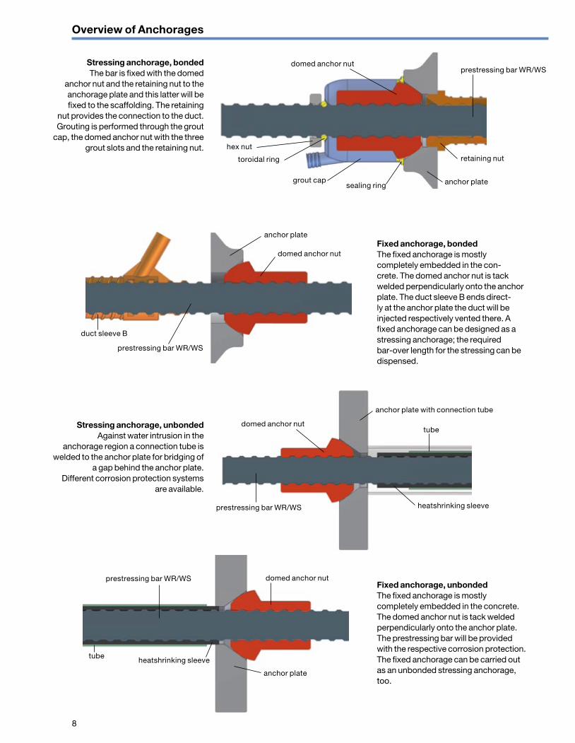
Stressing anchorage, bonded The bar is fixed with the domed
anchor nut and the retaining nut to the anchorage plate and this latter will be fixed to the scaffolding. The retaining
nut provides the connection to the duct. Grouting is performed through the grout
cap, the domed anchor nut with the three grout slots and the retaining nut.
Fixed anchorage, bondedThe fixed anchorage is mostly completely embedded in the con-crete. The domed anchor nut is tack welded perpendicularly onto the anchor plate. The duct sleeve B ends direct-ly at the anchor plate the duct will be injected respectively vented there. A fixed anchorage can be designed as a stressing anchorage; the required bar-over length for the stressing can be dispensed.
Stressing anchorage, unbondedAgainst water intrusion in the
anchorage region a connection tube is welded to the anchor plate for bridging of
a gap behind the anchor plate. Different corrosion protection systems
are available.
Fixed anchorage, unbondedThe fixed anchorage is mostly completely embedded in the concrete. The domed anchor nut is tack welded perpendicularly onto the anchor plate. The prestressing bar will be provided with the respective corrosion protection. The fixed anchorage can be carried out as an unbonded stressing anchorage, too.
domed anchor nutprestressing bar WR/WS
hex nut
toroidal ring
grout capsealing ring anchor plate
retaining nut
anchor plate
anchor plate with connection tube
domed anchor nut
duct sleeve B
prestressing bar WR/WS
domed anchor nuttube
heatshrinking sleeveprestressing bar WR/WS
domed anchor nut
anchor plate
prestressing bar WR/WS
tube heatshrinking sleeve
Overview of Anchorages
9
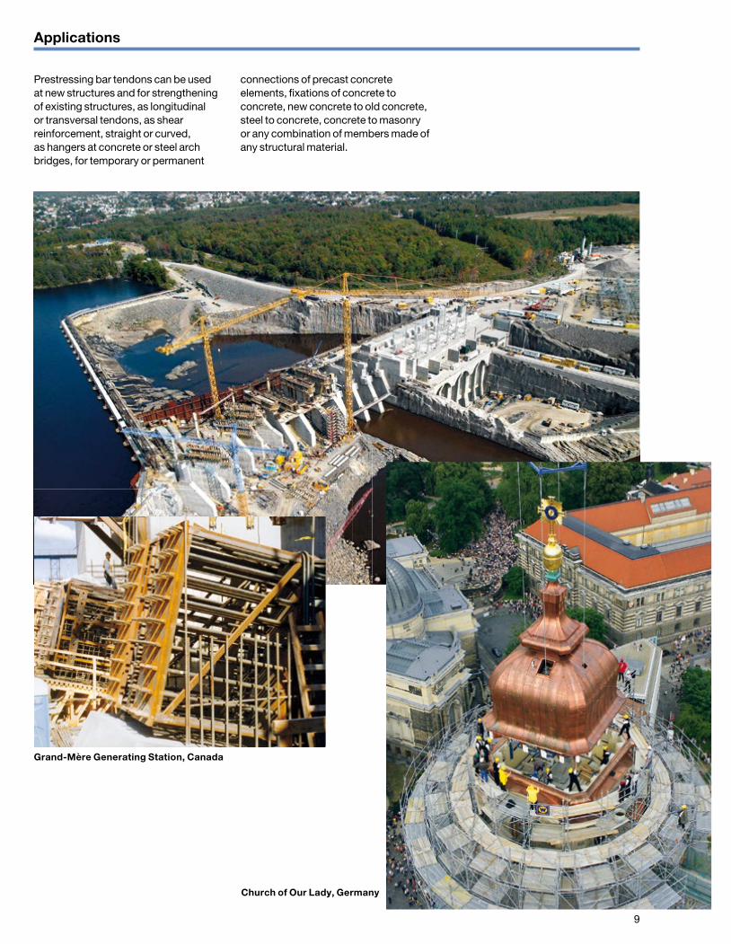
Prestressing bar tendons can be used at new structures and for strengthening of existing structures, as longitudinal or transversal tendons, as shear reinforcement, straight or curved, as hangers at concrete or steel arch bridges, for temporary or permanent
connections of precast concrete elements, fixations of concrete to concrete, new concrete to old concrete, steel to concrete, concrete to masonry or any combination of members made of any structural material.
Applications
Grand-Mère Generating Station, Canada
Church of Our Lady, Germany
10
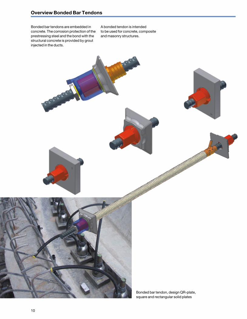
Bonded bar tendons are embedded in concrete. The corrosion protection of the prestressing steel and the bond with the structural concrete is provided by grout injected in the ducts.
A bonded tendon is intended to be used for concrete, composite and masonry structures.
Overview Bonded Bar Tendons
Bonded bar tendon, design QR-plate, square and rectangular solid plates

11
Overview Unbonded and External Bar Tendons
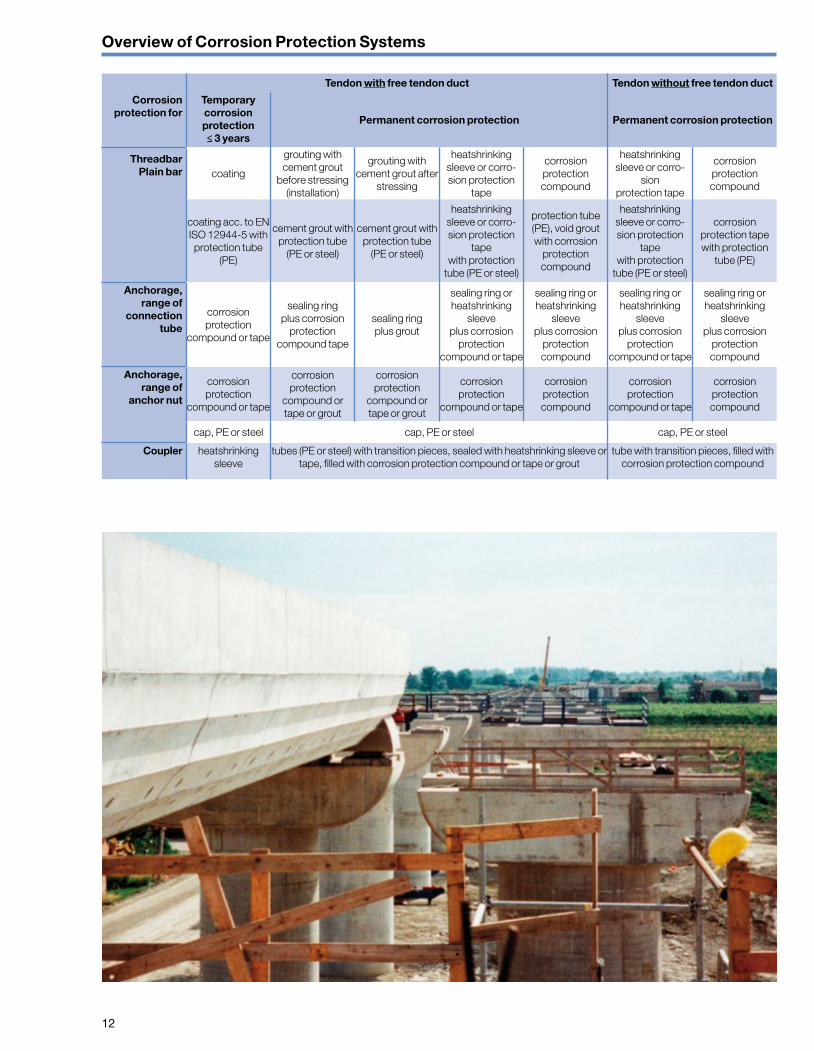
Unbonded and external bar tendons are installed either inside or outside the cross section of the structure. For corrosion protection various systems are available, all of which do not bond with the structure. The tendons may be
restressed at any time and depending on the tendon type, they can also be removed or exchanged.
Internal unbonded and external tendons are intended to be used for concrete,
composite, steel, timber and masonry structures.
The corrosions protection of unbonded and external tendons depends on an environmental conditions and service time.
Bar tendons with free tendon duct, permanent corrosion protection executed during grouting before stressing, design square and rectangular solid plates
Bar tendons with free tendon duct, permanent corrosion protection executed by heatshrinking sleeve, design square and rectangular solid plate
12
Tendon with free tendon duct Tendon without free tendon duct
Corrosion protection for
Temporary corrosion protection ≤ 3 years
Permanent corrosion protection Permanent corrosion protection
ThreadbarPlain bar coating
grouting with cement grout
before stressing (installation)
grouting with cement grout after
stressing
heatshrinking sleeve or corro-sion protection
tape
corrosion protection compound
heatshrinking sleeve or corro-
sion protection tape
corrosion protection compound
coating acc. to EN ISO 12944-5 with protection tube
(PE)
cement grout with protection tube
(PE or steel)
cement grout with protection tube
(PE or steel)
heatshrinking sleeve or corro-sion protection
tape with protection
tube (PE or steel)
protection tube (PE), void grout with corrosion
protection compound
heatshrinking sleeve or corro-sion protection
tape with protection
tube (PE or steel)
corrosion protection tape with protection
tube (PE)
Anchorage, range of
connection tube
corrosion protection
compound or tape
sealing ring plus corrosion
protection compound tape
sealing ring plus grout
sealing ring or heatshrinking
sleeve plus corrosion
protection compound or tape
sealing ring or heatshrinking
sleeve plus corrosion
protection compound
sealing ring or heatshrinking
sleeve plus corrosion
protection compound or tape
sealing ring or heatshrinking
sleeve plus corrosion
protection compound
Anchorage, range of
anchor nut
corrosion protection
compound or tape
corrosion protection
compound or tape or grout
corrosion protection
compound or tape or grout
corrosion protection
compound or tape
corrosion protection compound
corrosion protection
compound or tape
corrosion protection compound
cap, PE or steel cap, PE or steel cap, PE or steel
Coupler heatshrinking sleeve
tubes (PE or steel) with transition pieces, sealed with heatshrinking sleeve or tape, filled with corrosion protection compound or tape or grout
tube with transition pieces, filled with corrosion protection compound
Overview of Corrosion Protection Systems
13
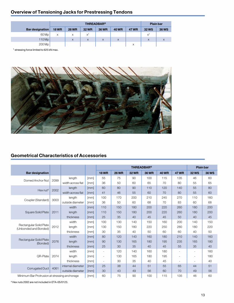
Geometrical Characteristics of Accessories
Overview of Tensioning Jacks for Prestressing Tendons
THREADBAR® Plain bar
Bar designation 18 WR 26 WR 32 WR 36 WR 40 WR 47 WR 32 WS 36 WS
Domed Anchor Nut 2099length [mm] 55 75 90 100 115 135 46 60
width across flat [mm] 36 50 60 65 70 80 55 65
Hex nut4 2002length [mm] 60 80 90 110 120 140 55 80
width across flat [mm] 41 46 55 60 70 80 55 60
Coupler (Standard) 3003length [mm] 100 170 200 210 245 270 110 160
outside diameter [mm] 36 50 60 68 70 83 60 68
Square Solid Plate 2011
width [mm] 110 150 180 200 220 260 180 200
length [mm] 110 150 180 200 220 260 180 200
thickness [mm] 25 35 40 45 45 50 40 45
Rectangular Solid Plate(Unbonded and Bonded)
2012
width [mm] 100 130 140 150 160 200 140 150
length [mm] 130 150 180 220 250 280 180 220
thickness [mm] 30 35 40 50 60 60 40 50
Rectangular Solid Plate(Bonded)
2076
width [mm] 80 120 140 160 180 210 140 160
length [mm] 90 130 165 180 195 235 165 180
thickness [mm] 25 30 35 40 45 55 35 40
QR-Plate 2074
width [mm] - 120 140 160 180 - - 160
length [mm] - 130 165 180 195 - - 180
thickness [mm] - 30 35 40 45 - - 40
Corrugated Duct 4061internal diameter [mm] 25 38 44 51 55 65 44 51
outside diameter [mm] 30 43 49 56 60 70 49 56
Minimum Bar Protrusion at stressing anchorage [mm] 60 75 90 100 115 135 46 60
THREADBAR® Plain bar
Bar designation 18 WR 26 WR 32 WR 36 WR 40 WR 47 WR 32 WS 36 WS
60 Mp x x x1 x1
110 Mp x x x x x x
200 Mp x1 stressing force limited to 625 kN max.
4 Hex nuts 2002 are not included in ETA-05/0123.
14
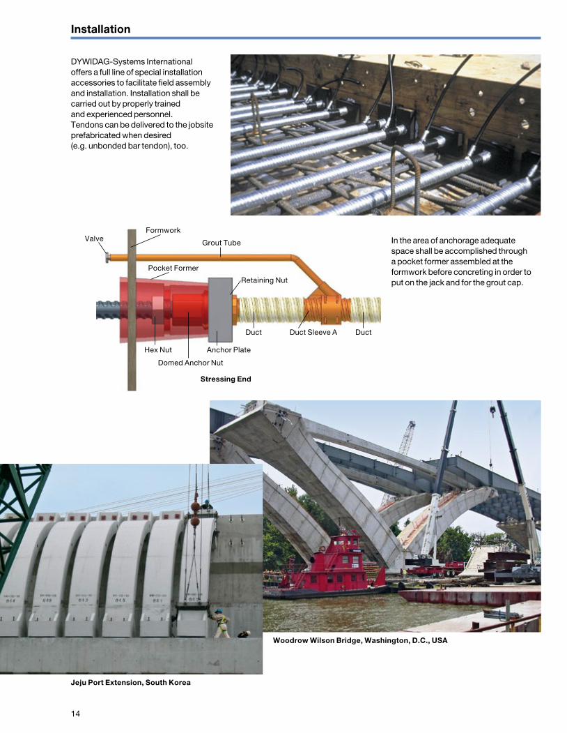
ValveFormwork
Grout Tube
Pocket Former
Duct Duct Sleeve A Duct
Anchor PlateHex Nut
Stressing End
Domed Anchor Nut
Retaining Nut
Installation
DYWIDAG-Systems International offers a full line of special installation accessories to facilitate field assembly and installation. Installation shall be carried out by properly trained and experienced personnel. Tendons can be delivered to the jobsite prefabricated when desired (e.g. unbonded bar tendon), too.
In the area of anchorage adequate space shall be accomplished through a pocket former assembled at the formwork before concreting in order to put on the jack and for the grout cap.
Jeju Port Extension, South Korea
Woodrow Wilson Bridge, Washington, D.C., USA

15
Stressing and Grouting
The small, light and conveniently operated DYWIDAG-Systems International jacks facilitate the stressing operation. Heavy lifting aids are generally not necessary.
Stressing notesStraight tendons are generally stressed from one end only. In order to reduce friction losses (especially in draped tendons) it is recommended to stress from both sides.
The prestressing load can be adjusted up and down at any given time until the tendon is fully grouted by simply reinstalling the jack. This allows partially stressing. Several controls during and after the stressing operation check the effective stressing load:
n bar protrusion at the anchorage before and after stressing to evaluate the effective elongation
n counter control for elongation during stressing operation
n gauge control for hydraulic pressure
To comply with exceptional high demands on accuracy for example on very short tendons special accessories can be applied to minimize the influence of alignment tolerances.
GroutingThe durability of bonded post-tensioned construction depends to a great degree on the success of the grouting operation. The hardened cement grout provides bond between concrete and tensile elements as well as primary long term corrosion protection (alkaline medium) for the prestressing steel.
DYWIDAG-Systems International has developed a grouting operation that is based on highly plasticized grout with thixotropic properties, and utilizes durable grouting equipment. Advanced methods such as pressure grouting, post-grouting and vacuum grouting are all results of many years of development.
Grouting is always done from a low-point of the tendon. This can be one of the anchorages with a grout cap with grout inlet or along the tendon utilizing an intermediate grout saddle. All grouting components are threaded for easy, fast and proper connection.
The jack is pushed over a pull rod coupler that is threaded onto the bar protrusion behind the domed anchor nut. The jack is then fixed with a pulling nut.
The tension load is hydraulically transfer-red. The domed anchor nut is tightened by an internal wrench. The bar 47 WR has a specially equipped stressing jack.
16
ØE
L
A B
ØD
ØC
F
ØE
A B
L
ØD
ØE
L
A B
ØD
ØC
F
ØE
A B
L
ØD
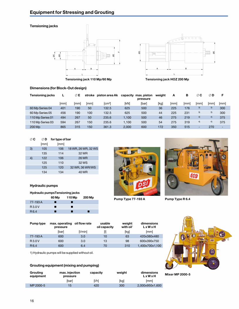
Equipment for Stressing and Grouting
Tensioning jacks
Dimensions (for Block-Out design)
Tensioning jacks L ∅ E stroke piston area Ak capacity max. piston weight A B ∅ C ∅ D F pressure [mm] [mm] [mm] [cm²] [kN] [bar] [kg] [mm] [mm] [mm] [mm] [mm]
60 Mp Series 04 401 190 50 132.5 625 500 36 225 176 3) 3) 300
60 Mp Series 05 456 190 100 132.5 625 500 44 225 231 3) 3) 300
110 Mp Series 01 494 267 50 235.6 1,100 500 46 275 219 4) 4) 375
110 Mp Series 03 594 267 150 235.6 1,100 500 54 275 319 4) 4) 375
200 Mp 865 315 150 361.3 2,000 600 172 350 515 - 270 -
∅ C ∅ D for type of bar [mm] [mm]
3) 105 106 18 WR, 26 WR, 32 WS
135 114 32 WR
4) 122 106 26 WR
125 110 32 WS
125 120 32 WR, 36 WR/WS
134 134 40 WR
Hydraulic pumps
Hydraulic pumps Tensioning jacks 60 Mp 110 Mp 200 Mp77-193 A n n
R 3.0 V n n
R 6.4 n n n
Pump type max. operating oil flow rate usable weight dimensions pressure oil capacity with oil1 L x W x H [bar] [l/min] [l] [kg] [mm]
77-193 A 600 3.0 10 63 420x380x480
R 3.0 V 600 3.0 13 98 600x390x750
R 6.4 600 6.4 70 310 1,400x700x1,100
1) Hydraulic pumps will be supplied without oil.
Grouting equipment (mixing and pumping)
Grouting max. injection capacity weight dimensionsequipment pressure L x W x H [bar] [l/h] [kg] [mm]
MP 2000-5 15 420 300 2,000x950x1,600
Pump Type R 6.4Pump Type 77-193 A
Mixer MP 2000-5
Tensioning jack 110 Mp/60 Mp Tensioning jack HOZ 200 Mp

0431
5-1/
10.1
6-w
eb s
c
A U S T R I A
A R G E N T I N A
A U S T R A L I A
B E L G I U M
B O S N I A A N D H E R Z E G O V I N A
B R A Z I L
C A N A D A
C H I L E
C O L O M B I A
C O S T A R I C A
C R O A T I A
C Z E C H R E P U B L I C
D E N M A R K
E G Y P T
E S T O N I A
F I N L A N D
F R A N C E
G E R M A N Y
G R E E C E
G U A T E M A L A
H O N D U R A S
H O N G K O N G
I N D O N E S I A
I T A L Y
J A P A N
K O R E A
L E B A N O N
L U X E M B O U R G
M A L A Y S I A
M E X I C O
N E T H E R L A N D S
N O R W A Y
O M A N
P A N A M A
P A R A G U A Y
P E R U
P O L A N D
P O R T U G A L
Q A T A R
S A U D I A R A B I A
S I N G A P O R E
S O U T H A F R I C A
S P A I N
S W E D E N
S W I T Z E R L A N D
T A I W A N
T H A I L A N D
T U R K E Y
U N I T E D A R A B E M I R A T E S
U N I T E D K I N G D O M
U R U G U A Y
U S AV E N E Z U E L A
www.dywidag-systems.com
Please note: This brochure serves basic information purposes only. Technical data and information provided herein shall be considered non-binding and may be subject to change without notice. We do not assume any liabilityfor losses or damages attributed to the use of this technical data and any improper use of our products. Should you require further information on particular products, please do not hesitate to contact us.
AustriaDYWIDAG-SystemsInternational GmbHAlfred-Wagner-Strasse 14061 Pasching/Linz, AustriaPhone +43-7229-61 04 90Fax +43-7229-61 04 980 E-mail [email protected]
FranceDSI-ArtéonRue de la Craz Z.I. des Chartinières 01120 Dagneux France Phone +33-4-78 79 27 82Fax +33-4-78 79 01 56E-mail [email protected]
GermanyDYWIDAG-SystemsInternational GmbHSchuetzenstrasse 2014641 Nauen, GermanyPhone +49 3321 44 18 0Fax +49 3321 44 18 18E-mail [email protected]
DYWIDAG-SystemsInternational GmbHMax-Planck-Ring 140764 Langenfeld, GermanyPhone +49 2173 79 02 0Fax +49 2173 79 02 20E-mail [email protected]
DYWIDAG-SystemsInternational GmbHGermanenstrasse 886343 Koenigsbrunn, GermanyPhone +49 8231 96 07 0Fax +49 8231 96 07 10E-mail [email protected] www.dywidag-systems.de
DYWIDAG-SystemsInternational GmbHSiemensstrasse 885716 Unterschleissheim, GermanyPhone +49-89-30 90 50-100Fax +49-89-30 90 50-120E-mail [email protected]
ItalyDYWIT S.P.A. Viale Europa 72 Strada A 7/9 20090 Cusago (MI), ItalyPhone +39-02-901 65 71Fax +39-02-901 65 73 01E-mail [email protected]
NetherlandsDYWIDAG-SystemsInternational B.VVeilingweg 25301 KM Zaltbommel, NetherlandsPhone +31-418-57 89 22Fax +31-418-51 30 12E-mail [email protected]
PolandDYWIDAG-SYSTEMSINTERNATIONAL Sp. z o.o.ul. Przywidzka 4/6880-174 Gdansk, PolandPhone +48-58-300 13 53Fax +48-58-300 13 54E-mail [email protected] www.dywidag-systems.pl
PortugalDYWIDAG SISTEMAS CONSTRUCTIVOS, SARua D. Manuel I, n.º24 AQuinta da Parreirinha2695-003 Bobadela (Loures), PortugalPhone +351-21-89 22 890Fax +351-21-89 22 899E-mail [email protected]
SpainDYWIDAG SISTEMAS CONSTRUCTIVOS, S.A.Avd/de la Industria, 4Pol. Ind. la Cantuena28947 Fuenlabrada (Madrid), SpainPhone +34-91-642 20 72Fax +34-91-642 27 10E-mail [email protected]
United KingdomDYWIDAG-Systems International Ltd.Northfield RoadSoutham, WarwickshireCV47 0FG, Great BritainPhone +44-1926-81 39 80Fax +44-1926-81 38 17E-mail [email protected]