Embed Size (px)
Citation preview

Acta Technica 62 (2017), No. 7A, 323–334 c© 2017 Institute of Thermomechanics CAS, v.v.i.
Dynamic data modeling and
simulation method of machine system
based on grid finite element analysis
Huachuan Li1, Zhugao Pang2, Huijie Yu3
Abstract. The impact mechanical system of a new hydraulic power piling machine is re-searched and a dynamic data modeling and simulation method of mechanical system based onmeshing finite element analysis is proposed. Based on a large number of research literatures on im-pact mechanical system dynamics at home and abroad, the finite volume method discrete equationis used and the Galerkin discrete finite element is adopted to approach it by mechanical elasticityequation to obtain the 3D unstructured mesh model of impact mechanical system of hydraulicpower piling machine. The impact piling force of impact mechanical system of hydraulic powerpiling machine and meshing finite element of key parts are researched, including the punch hammer,tension and compression box, pull rod, pile caps etc. Finally, the LS-DYNA dynamics simulationsoftware is used to simulate the finite elements for the impact mechanical system of hydraulic powerpiling machine. The results show the proposed method is effective.
Key words. Meshing, Finite elements, Mechanical system, Modeling and simulation.
1. Introduction
Among the environmental test devices, the vibration, impact, acceleration andswing test devices are dynamic test devices. The system characteristics of dynamictest devices are relatively complicated and multiple parameters are mutually com-bined, mainly including the frequency functions, which makes the design difficult.Only the simplified design calculation based on the analytic formula is used for theearlier design technique. Taking the servo valve of hydraulic vibration platform asan example, the load impact is not taken into consideration in the output flow calcu-
1Department of mechanical engineering , Guangxi technological college of machinery and elec-tricity, GUANGxi nanning, 530007, China
2School of mechanical engineering, Guangxi University, GUANGxi nanning, 530004, China3School of mechanical engineering , University of shanghai for science and technology, shanghai,
200093, China
http://journal.it.cas.cz

324 HUACHUAN LI, ZHUGAO PANG, HUIJIE YU
lation or the load is processed based on a fixed value. But in fact, the load is changedall the time. For the servo valve, with increasing of frequency, the flow will decreaseand the phase lag will continuously increase. The phase lag has a significant impacton the system stability. Such simplified design method cannot carefully and com-pletely predict and understand the dynamic characteristics of system. Therefore,the system design risks can be increased.
The simulation technique is an effective means to analyze the dynamic system.Such simulation technique incorporates various related dynamic variables into adifferential equation, uses model (circuit or software) to express the dynamic char-acteristics of system and operates the model to obtain variable-time changing curve.Latterly, with the development of all-digital simulation technique, the differentialequation and each nonlinear link or module can enter into the system model. There-fore, the degree of simulation is further increased. With popularization of micro-computer and simulation software, the simulation technique is increasingly used inall walks of life. Several examples are used in this paper to introduce the appli-cation of simulation technique in design of dynamic environment test device. Thesimulation technique has experiences the analog computer, hybrid digital-analogcomputer and all-digital computer. In 1946, the analog computer was invented inAmerica, which could simulate different physical phenomenon, such as the flightpath of missile and airplane etc. It indicates the beginning of analog simulationtechnique. Since then, many analog machines came forth. The period from the1950s to 1560s is the golden age for analog computer. Although the analog com-puter obtains a great success, many problems are exposed, such as insufficient dataaccuracy, difficulty in realizing the interpolation function and failure of satisfactionof data control system requirements etc. In the end of the 1950s, the hybrid analogcomputer appeared due to the development requirements of missile technology. Theperiod from the 1960s to middle 1970s is the flourishing age of hybrid analog com-puter. America ADI Company invented the all-digital simulation computer AD10in 1978, which indicates that the all-digital simulation computer takes the lead infierce competition of hybrid analog computer and digital analog computer and thenew era of all-digital simulation comes. In 1973, the special hydraulic simulationsoftware HYDSIM was successfully invented in America. Then, the hydraulic sim-ulation software was continuously developed and improved in Europe and America.In 1980, DSH (Germany) and HASP (the UK) etc. were successively issued. OnOctober 15, 1985, the first all-digital simulation computer “Yinhe I Simulation Com-puter (YH-F1)” was successfully invented in China, which indicates China enters anall-digital simulation era. Hereafter, many new simulation computers appears. Thesimulation technique is firstly used in aerospace field which is the birthplace of sim-ulation computer. Only the important and complex dynamic system design can beaffordable. After popularization of microcomputer and graphical programming ofsimulation software, the simulation technique is widely used and the symbolic nodeis issuance of MATLAB/Simulink simulation software. MATLAB/Sim-Mink playsan important part in simulation software. It can be considered that Simulink isthe watershed. Before such period, the modeling is based on statement description,the relationship between modules is defined based on the statement and the sys-

DYNAMIC DATA MODELING AND SIMULATION METHOD 325
tem module composition and relationship between modules cannot be visually seen.Simulink provides a graphic modeling method and the complex simulation model canbe built only by simple mouse drag operation. Its appearance is presented by blockchart and the layered structure is used. In the view of modeling, it is applicableto top-down design process (from concept, function, system, subsystem to device)bottom-up reverse process design. In the view of analysis research, the Simulink notonly enables the users know the dynamic details of specific links, but also clearlyunderstands the information exchange between each device, subsystem and systemand grasps interaction between each part. It is very convenient for modeling andbeneficial to error-checking and correction of model. Except quick and convenientmodeling, other functions are powerful as well. For example„ it can process dif-ferent systems, including the linear and nonlinear system; discrete, continuous andhybrid system; single-task and multi-task discrete event system. Simulink 6.5 is themilestone version and its acceleration mode can make the computing speed increaseseveral tens of times and hundred times.
The finite element and boundary element method is often used in mechanicaldynamics analysis and the finite volume method combined with hydromechanicsmodeling method is also adopted, such as the finite element and extended finiteelement etc. It is very difficult to implement stable discretization for the nonlinearproblems. The parameter stabilization is carried out in literature [10] to obtainthe stabilization equation for contact mechanical problems. The Nitsche processingmethod is proposed in literature [11] and such method can be considered as consis-tent penalty function method. When the model parameters are suitably selected,the corresponding discrete equation set can be well adjusted. The impact mechan-ical system of a new hydraulic power piling machine is researched and a dynamicdata modeling and simulation method of mechanical system based on meshing fi-nite element analysis is proposed in this paper. The LS-DYNA dynamics simulationsoftware is used to simulate the finite elements for the impact mechanical system ofhydraulic power piling machine. The results show the proposed method is effective.
2. Vibration dynamic model of mechanical system of pilingmachine
In wave mechanics model, the pull rod and precast pile used in the impact me-chanical system of hydraulic power piling machine is simplified as the elastic rod,where the transmission reflection of stress wave in pull rod is taken into considerationwhen the pull rod is simplified as the elastic rod, which makes the complex wave me-chanics model and complicated solution procedure. The vibration mechanics theoryis used to simplify the pull rod as single spring-single mass block system and thenthe vibration mechanics model more simple and convenient than wave mechanicsmodel can be built to obtain impact pilling force. As the complexity of mechanicalmodel will not be increased if the precast pile is simplified as elastic rod, the precastpile is still assumed as elastic rod with equal wave drag in wave mechanics model.
According to the vibration mechanicals theory, the pull rod is simplified as thesystem composed of single mass unit and single spring unit (rigidity of pull rod),

326 HUACHUAN LI, ZHUGAO PANG, HUIJIE YU
namely, the pull rod is simplified as a system with single degree of freedom. The pullrod mass unit is set as m4 (the mass is uniformly distributed on pile cap, tensionand compression box) and the equivalent rigidity is set as k2. Other assumptionsare same as wave mechanics model assumption. The structure of impact mechanicalsystem of hydraulic power piling machine can be simplified as shown in Fig. 1.
Fig. 1. Structure model of impact mechanical system of piling machine(1. Pile cap; 2. crash pad; 3. pull rod (spring); 5. punch hammer; 6. buffer spring;
7. tension and compression box; 8. working medium)
3. Mechanical system dynamics modeling based on finiteelement
3.1. Mesh structure discretization solutions
The geometrical elements are used to conduct mesh generation. In general, thetetrahedron is used to represent the substrate and the triangle element is used torepresent the stress surface. The two-dimensional model mesh is used in order tosimplify description as shown in Fig. 2. But in fact, the design method is threedimensional.
In Fig. 2a, Ω refers to the physical region, Γ refers to the outer shape of modeland Γf is defined as stress surface. In Fig. 2b, the triangle is used to represent thesubstrate and the heavy line represents mechanical contact area. This geometry meshis applicable to mechanical problems. In Fig. 2c, the control volume is associatedwith each element in mesh. Pressurep, density ρf and viscosity µf are all associatedwith cell center. The displacement is unknown and u is associated with top pointof substrate. In Fig. 2d, different nodes are used to represent the displacement oneach side in mechanical contact area. In addition, the traction vector t is associatedwith each mechanical contact area surface.

DYNAMIC DATA MODELING AND SIMULATION METHOD 327
Fig. 2. Two-dimensional model mesh
3.2. Mechanics equation and model approximation in dis-crete mechanical contact area
The stress equation of finite volume method is used to conduct discretization.Based on the approximate magnetic flow on two points, the flow rate between twoadjacent controlled quantities can represent the pressure differential function:
Qij = λTij(pi − pj) . (1)
Where, Qij is the mass flow rate between controlled quantity i and j. Thedynamics fluidity can be defined as λ = ρf/µf . The geometric transfer part is Tij .The approximation scheme of finite volume of backward Euler time and flow rate isadopted and the flow rate equation (1) can be approximated as:
pf in+lφn+1
i − pnfiϕni
∆tVi =
∑j
Qij + qivi . (2)
Where, Vi is volume i and the time interval is ∆t. The index n + 1 and nrespectively refer to the current and next step.
3.3. Quasi-static mechanical elasticity equation
Under the case of external boundary Γ and internal boundary Γf , the potentialenergy of mechanical contact defined in formula (2-3) can be further represented as:

328 HUACHUAN LI, ZHUGAO PANG, HUIJIE YU
Π =1
2
∫Ω
ε : σdΩ−∫
Ω
uρgdΩ−∫
Γ
utdΓ
−∫
Γf
u+t+f dΓ−
∫Γf
u−t−f dΓ .
(3)
Where, t is the total traction vector on boundary Γ. The total traction force t−fand t+f are respectively in opposite side of fracture interface. Based on the continuitycondition tf = t+f = t−f , it can be obtained that:
Π =1
2
∫Ω
ε : σdΩ−∫
Ω
uρgdΩ−∫
Γ
utdΓ
−∫
Γf
(u+ − u−)tfdΓ(4)
Where, tf combines with the impact of mechanical pressure p and effective stressof Terzaghi σ′.
tf = −σn = −(σ − Ip)n = tNn+ tT τ + pn . (5)
The gap function g can be expressed as the displacement function:
g = u+ − u− = (gN , gT ) . (6)
Therefore, the following potential-energy function can be obtained:
Π =1
2
∫Ω
ε : σdΩ−∫
Ω
uρgdΩ−∫
Γ
utdΓ
−∫
Γf
gNpdΓ− (
∫Γf
gN tN + gT tT )dΓ(7)
The differential is used to calculate and obtain the minimum potential energy:
δΠ =1
2
∫Ω
δε : σdΩ−∫
Ω
δuρgdΩ−∫
Γ
δutdΓ
−∫
Γf
δgNpdΓ− (
∫Γf
gN tN + δgT tT )dΓ = 0 .(8)
The finite element approximation can be made based on the node. Therefore,the displacement can be defined as:
u(ξ) ≈∑a
Na(ξ)ua . (9)
Where, ua is the node displacement value and Na is the shape function. The

DYNAMIC DATA MODELING AND SIMULATION METHOD 329
gap function of impact mechanical system of hydraulic power piling machine can bedefined as:
g(ξ) = u+(ξ)− u−(ξ)
≈∑a
Na(ξ)(u+a − u−a ) =
∑a
Naga .(10)
Where, u+ and u− respectively refer to the displacement on both sides of me-chanical contact area. The surface discretization can be expressed as Γf = ∪eΓf,e
and the stress area can be expressed as:∫Γf
δgNpdΓ−∫
Γf
(δgN tN + δgT tT )dΓ
≈∑e
×∫
Γf,e
∑a
δ(gN )aNapdΓ
−∑e
×∫
Γf,e
(∑a
δ(gN )aNatN +∑a
δ(gT )aNatT )dΓ .
(11)
The traction vector (tN , tT ) is shown above. Under the ideal condition, thefriction law can be obtained based on Kuhn-Tucker relation: tN ≥ 0, gN ≥ 0, tNgN = 0, gT (ξ)− η ∂Φ
∂tT= 0 ,
Φ = |tT | − F(tN ) ≤ 0, η ≥ 0,Φ ≤ 0, ηΦ = 0 .
(12)
It can be known that the slip phenomenon will occur when Φ = 0; the adherencephenomenon will occur when Φ < 0 and gT = 0. The Kuhn-Tucker constraint andadherence/slip rules can be replaced with: gT (ξ)− η ∂
∂tTΦ =
1
εTtT
tN = εNgN , η ≥ 0,Φ ≤ 0, ηΦ = 0 .
(13)
Where, εN 1, εT 1 is penalty factor. εN is influence by man-made rigidityon stress surface. Based on the above formula, it can be known that the stress willoccur when gN > 0.
In deformation process, the contact area is directly proportional to the forceimposed. Therefore, for the normal contact surface, the following formula is satisfied:
N (gN ) =kng0
g0 · gNgN . (14)
Where, kn is the initial normal rigidity. Under the “ideal” condition, the surface

330 HUACHUAN LI, ZHUGAO PANG, HUIJIE YU
roughness contact can be considered as below:tN = N (gN ), gN ≤ g0 ,
gT − η∂
∂tTΦ =
1
εTiT
η ≥ 0,Φ ≤ 0, ηΦ = 0 .
(15)
The return mapping algorithm can be used to assess the traction vector as below:
tn+1N = N(gn+1
N ) ,
ttrialT = tnT + εT (gn+1T − gnT ) ,
Φtrial = |ttrialT | − F(tn+1N ) ,
tn+1T = ttrialT , ifΦtrial ≤ 0 ,
|tn+1T | = F(tn+1
N ), ifΦtrial > 0 .
(16)
Where, the subscript n+ 1 and n respectively refers to the current and previousstep.
4. Experimental analysis
4.1. Mesh model building
The hypermesh with powerful mesh generation function is selected to conductmesh generation for the three-dimensional model of impact mechanical system. Thegood model will be built for the impact mechanical system of hydraulic power pil-ing machine in Pro/E, the model is imported into Hypermesh, the surface mesh isfirstly built for each part in Hypermesh, the high-precision hexahedral mesh canbe obtained after tension and adjustment of surface mesh, where 3D solid elementsolid164 is used for the mesh element, the key part material and its overall modelmesh are shown in Fig. 3a-d. Fig. 3a is the punch hammer mesh model, Fig. 3bis the tension and compression box mesh model, Fig. 3c is the local mesh modelof pile cap and pull rod and Fig. 3d is the local mesh model of impact mechanicalsystem. For the impact mechanical system model, the number of element is 89800and the number of node is 124596.
Table 1. Material property of key parts
Name Elementtype Material Elasticity
modulus (Gpa)Poissonratio
Density(kg.mm/3)
Impact block solid164 Steel 207GPa 0.28 7.83×10⁻⁶Tension and
compression box solid164 Steel 207GPa 0.28 7.83×10⁻⁶
Pull rod solid164 Steel 207GPa 0.28 7.83×10⁻⁶Pile cap solid164 Steel 207GPa 0.28 7.83×10⁻⁶
Precast pile solid164 Concrete 30GPa 0.2 2.4×10⁻⁶

DYNAMIC DATA MODELING AND SIMULATION METHOD 331
(a) Punch hammer (b) Tension and compression box
(c) Pile cap and pull rod (d) Impact mechanical system
Fig. 3. Mesh model of key parts
Fig. 3. Mesh model of key parts
The finite element mesh model of impact mechanical system of hydraulic powerpiling machine is imported into ANSYS to conduct pretreatment. The pretreatmentprocess mainly includes the following septs:
(1) Establish part group: establish 7 part groups, namely, punch hammer, tensionand compression box, pull rod, pile cap, pile, spring 1 and spring 2. Spring 1 is thespring rigidity between punch hammer and tension and compression box, namely,k1 = 1×10⁹N/m; spring 2 is the spring rigidity between pile cap and pile, namely,k2 = 4×10⁸N/m.
(2) Define the load and boundary conditions: add 6.12m/s of initial speed basedon the design parameters of impact mechanical system of hydraulic power pilingmachine. Take no account of the impacts of soil layer on piling process in simulation;adopt full constraints in the bottom of precast pile.
(3) Establish the analysis options: set the computation time as 80ms, the outputtype as LS-DYNA and the output time interval as 0.2ms.
(4) Export setting: output the established simulation model in the format ofK document; revise the contact and collision parameters etc. in the notebook andimport the revised K document into LS-DYNASolver. As the impact process istransferred through spring, the automatic single face node-surface contact is adoptedand the keyword is *CONTACT_AUTOMATIC_NODES_TO_SURFACE.
4.2. Impact piling force analysis
The contact surface element stress can be obtained from the finite element sim-ulation results to calculate the piling force and compare with the theoretical valueobtained above. Fig. 4a respectively represents the position of pile cap plane unit45099 and the stress curve of such unit in axial direction (X direction) of precast pile.Fig. 4b represents the impact pile force curve under the theory of wave mechanics
332 HUACHUAN LI, ZHUGAO PANG, HUIJIE YU
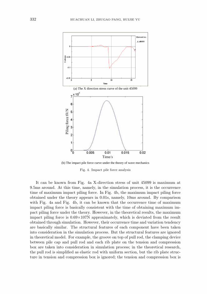
(a) The X direction stress curve of the unit 45099
(b) The impact pile force curve under the theory of wave mechanics
Fig. 4. Impact pile force analysis
It can be known from Fig. 4a X-direction stress of unit 45099 is maximum at9.5ms around. At this time, namely, in the simulation process, it is the occurrencetime of maximum impact piling force. In Fig. 4b, the maximum impact piling forceobtained under the theory appears in 0.01s, namely, 10ms around. By comparisonwith Fig. 4a and Fig. 4b, it can be known that the occurrence time of maximumimpact piling force is basically consistent with the time of obtaining maximum im-pact piling force under the theory. However, in the theoretical results, the maximumimpact piling force is 0.69×10⁷N approximately, which is deviated from the resultobtained through simulation. However, their occurrence time and variation tendencyare basically similar. The structural features of each component have been takeninto consideration in the simulation process. But the structural features are ignoredin theoretical model. For example, the groove on top of pull rod, the clamping devicebetween pile cap and pull rod and each rib plate on the tension and compressionbox are taken into consideration in simulation process; in the theoretical research,the pull rod is simplified as elastic rod with uniform section, but the rib plate struc-ture in tension and compression box is ignored; the tension and compression box is

DYNAMIC DATA MODELING AND SIMULATION METHOD 333
simplified as a rigid body, these structural deviations will have an impact on trans-mission of stress wave in system and cause deviation between simulation results andtheoretical results.
5. Conclusion
The impact mechanical system of a new hydraulic power piling machine is re-searched and a dynamic data modeling and simulation method of mechanical systembased on meshing finite element analysis is proposed. Through LS-DYNA finite el-ement analysis on the impact mechanical system of hydraulic power piling machine,it can be know that: (1) The LS-DYNA simulation curve and wave mechanicalstheory calculation curve for impact piling force are basically similar, but the theirmaximum impact piling force is different. (2) From the hammer stress change cloudchart, it can be know that the stress is concentrated on the contact point of punchhammer and spring, the spring should be uniformly arranged or the crash pad canbe used to replace the spring to reduce stress concentration of punch hammer.
Acknowledgement
Research project of Guangxi Education Department: Product Collaborative De-sign Based on 3D CAD and PDM (LX2014552).
References
[1] K.Miller, K.Chinzei, G.Orssengo, et al.: Mechanical properties of brain tissuein-vivo: experiment and computer simulation[J]. Journal of biomechanics, 33 (2000),No. 11, 1369–1376.
[2] C.A. Felippa, K.C. Park, C. Farhat: Partitioned analysis of coupled mechanicalsystems[J]. Computer methods in applied mechanics and engineering, 190 (2001),No. 24, 3247–3270.
[3] C.Basdogan, S.De, J.Kim J., et al.: Haptics in minimally invasive surgicalsimulation and training [J]. IEEE computer graphics and applications, 24 (2004), No. 2,56–64.
[4] M.Friswell, J. E.Mottershead: Finite element model updating in structural dy-namics[M]. Springer Science & Business Media (2013).
[5] F.Cirak, M. J. Scott, E.K.Antonsson, et al.: Integrated modeling, finite-element analysis, and engineering design for thin-shell structures using subdivision[J].Computer-Aided Design, 34 (2002), No. 2, 137–148.
[6] O.Kolditz, S. Bauer, L. Bilke, et al.: OpenGeoSys: an open-source initiativefor numerical simulation of thermo-hydro-mechanical/chemical (THM/C) processesin porous media[J]. Environmental Earth Sciences, 67 (2012), No. 2, 589–599.
[7] K.Mao, B. Li, J.Wu, et al.: Stiffness influential factors-based dynamic modelingand its parameter identification method of fixed joints in machine tools[J]. InternationalJournal of Machine Tools and Manufacture, 50 (2010), No. 2, 156–164.
[8] C. J. Li, H. Lee: Gear fatigue crack prognosis using embedded model, gear dynamicmodel and fracture mechanics[J]. Mechanical systems and signal processing, 19 (2005),No. 4, 836–846.

334 HUACHUAN LI, ZHUGAO PANG, HUIJIE YU
[9] D.A. Steinman, J. S.Milner, C. J.Norley, et al.: Image-based computationalsimulation of flow dynamics in a giant intracranial aneurysm[J]. American Journal ofNeuroradiology, 24 (2003), No. 4, 559–566.
[10] K.Miller, G. Joldes, D. Lance, et al.: Total Lagrangian explicit dynamics finiteelement algorithm for computing soft tissue deformation[J]. International Journal forNumerical Methods in Biomedical Engineering, 23 (2007), No. 2, 121–134.
[11] Y.Y. Zhang, J.W.Chan, A.Moretti, and K.E.Uhrich: Designing Polymerswith Sugar-based Advantages for Bioactive Delivery Applications, Journal of ControlledRelease, 219 (2015), 355–368.
[12] Y.Y. Zhang, Q. Li, W. J.Welsh, P.V.Moghe, and K.E.Uhrich: Micellarand Structural Stability of Nanoscale Amphiphilic Polymers: Implications for Anti-atherosclerotic Bioactivity, Biomaterials, 84 (2016), 230–240.
[13] J.W.Chan, Y.Y. Zhang, and K.E.Uhrich:Amphiphilic Macromolecule Self-Assembled Monolayers Suppress Smooth Muscle Cell Proliferation, BioconjugateChemistry, 26 (2015), No. 7, 1359–1369.
[14] D. S.Abdelhamid, Y.Y. Zhang, D.R. Lewis, P.V.Moghe, W. J.Welsh, andK.E.Uhrich: Tartaric Acid-based Amphiphilic Macromolecules with Ether LinkagesExhibit Enhanced Repression of Oxidized Low Density Lipoprotein Uptake, Biomateri-als, 53 (2015), 32–39.
Received May 7, 2017


![Optimizationoftradeoffbetweenride ...journal.it.cas.cz/62(2017)-KHO/Paper II-106.pdf · [2] M.Sever, H.Yazici: Disturbance observer based optimal controller design for active suspension](https://img.dokumen.tips/doc/110x75/5f8dadaaa8563365637521d8/optimizationoftradeoibetweenride-2017-khopaper-ii-106pdf-2-msever.jpg)