Embed Size (px)
Citation preview
Dynamic three-dimensional sensing for specular
surface with monoscopic fringe reflectometry
Lei Huang,* Chi Seng Ng, and Anand Krishna Asundi
School of Mechanical and Aerospace Engineering, Nanyang Technological University, Singapore 639798,
Singapore *[email protected]
Abstract: Dynamic full-field three-dimensional sensing of specular
reflective surfaces can be conveniently implemented with fringe reflection
technique. A monoscopic fringe reflectometric system can be adopted as a
simple measuring setup. With the assistance of the windowed Fourier ridges
method as an advanced fringe demodulation technique, only one cross
grating is needed to reconstruct the three-dimensional surface shape
changes. A suitable calibration enables determination of the actual
three-dimensional surface profile. Experimental results of water wave
variations are shown to demonstrate the feasibility of the proposed approach.
©2011 Optical Society of America
OCIS codes: (150.6910) Three-dimensional sensing; (120.5700) Reflection; (120.2650) Fringe
analysis; (120.5050) Phase measurement.
References and links
1. Y. Tang, X. Su, Y. Liu, and H. Jing, “3D shape measurement of the aspheric mirror by advanced phase measuring
deflectometry,” Opt. Express 16(19), 15090–15096 (2008). 2. Y. Tang, X. Su, F. Wu, and Y. Liu, “A novel phase measuring deflectometry for aspheric mirror test,” Opt.
Express 17(22), 19778–19784 (2009).
3. W. Zhao, X. Su, Y. Liu, and Q. Zhang, “Testing an aspheric mirror based on phase measuring deflectometry,” Opt. Eng. 48(10), 103603 (2009).
4. S. Werling, M. Mai, M. Heizmann, and J. Beyerer, “Inspection of specular and partially specular surfaces,” Metro.
Measure. Syst. 16(3) 415–431 (2009). 5. J. Balzer, and S. Werling, “Principles of Shape from Specular Reflection,” Measurement 43(10), 1305–1317
(2010).
6. Y. M. Zhang, H. S. Song, and G. Saeed, “Observation of a dynamic specular weld pool surface,” Meas. Sci. Technol. 17(6), L9–L12 (2006).
7. T. Bothe, W. Li, C. von Kopylow, and W. P. O. Jüptner, “High-resolution 3D shape measurement on specular
surfaces by fringe reflection,” in Optical Metrology in Production Engineering, (SPIE, 2004), 411–422. 8. M. C. Knauer, J. Kaminski, and G. Häusler, “Phase measuring deflectometry: a new approach to measure specular
free-form surfaces,” in Optical Metrology in Production Engineering, (SPIE, 2004), 366–376.
9. M. Petz, and R. Tutsch, “Reflection grating photogrammetry: a technique for absolute shape measurement of specular free-form surfaces,” in Optical Manufacturing and Testing VI, (SPIE, 2005), 58691D1–58691D12.
10. X. Su, and Q. Zhang, “Dynamic 3-D shape measurement method: A review,” Opt. Lasers Eng. 48(2), 191–204
(2010). 11. Q.-C. Zhang, and X.-Y. Su, “An optical measurement of vortex shape at a free surface,” Opt. Laser Technol.
34(2), 107–113 (2002).
12. Q. Zhang, and X. Su, “High-speed optical measurement for the drumhead vibration,” Opt. Express 13(8), 3110–3116 (2005).
13. Q. Zhang, X. Su, Y. Cao, Y. Li, L. Xiang, and W. Chen, “Optical 3-D shape and deformation measurement of
rotating blades using stroboscopic structured illumination,” Opt. Eng. 44(11), 113601 (2005). 14. Y. Watanabe, T. Komuro, and M. Ishikawa, “955-fps Real-time shape measurement of a moving/deforming
object using high-speed vision for numerous-point analysis,” In ICRA (2007), 3192–3197.
15. L.-C. Chen, Y.-T. Huang, X.-L. Nguyen, J.-L. Chen, and C.-C. Chang, “Dynamic out-of-plane profilometry for nano-scale full-field characterization of MEMS using stroboscopic interferometry with novel signal
deconvolution algorithm,” Opt. Lasers Eng. 47(2), 237–251 (2009).
16. S. Zhang, and P. S. Huang, “High-resolution, real-time three-dimensional shape measurement,” Opt. Eng. 45(12), 123601 (2006).
17. S. Zhang, “Recent progresses on real-time 3D shape measurement using digital fringe projection techniques,”
Opt. Lasers Eng. 48(2), 149–158 (2010).
#146490 - $15.00 USD Received 26 Apr 2011; revised 26 May 2011; accepted 26 May 2011; published 17 Jun 2011(C) 2011 OSA 20 June 2011 / Vol. 19, No. 13 / OPTICS EXPRESS 12809
18. Z. Zhang, “A flexible new technique for camera calibration,” IEEE Trans. Pattern Anal. Mach. Intell. 22(11),
1330–1334 (2000). 19. J. Y. Bouguet, Camera calibration toolbox for matlab, please see
http://www.vision.caltech.edu/bouguetj/calib_doc/.
20. W. H. Southwell, “Wave-front estimation from wave-front slope measurements,” J. Opt. Soc. Am. 70(8), 998–1006 (1980).
21. W. Li, T. Bothe, C. von Kopylow, and W. P. O. Jüptner, “Evaluation methods for gradient measurement
techniques,” in Optical Metrology in Production Engineering, (SPIE, 2004), 300–311. 22. X. Su, and W. Chen, “Fourier transform profilometry: A review,” Opt. Lasers Eng. 35(5), 263–284 (2001).
23. Q. Kemao, “Windowed Fourier transform for fringe pattern analysis,” Appl. Opt. 43(13), 2695–2702 (2004).
24. Z. Wang, and H. Ma, “Advanced continuous wavelet transform algorithm for digital interferogram analysis and processing,” Opt. Eng. 45(4), 045601 (2006).
25. L. Huang, Q. Kemao, B. Pan, and A. K. Asundi, “Comparison of Fourier transform, windowed Fourier transform,
and wavelet transform methods for phase extraction from a single fringe pattern in fringe projection
profilometry,” Opt. Lasers Eng. 48(2), 141–148 (2010).
1. Introduction
Three-dimensional (3D) sensing for specular objects is required in many applications in
research and industry [1–6]. A practical and suitable method to measure specular reflective
surfaces is phase measuring reflectometry (or deflectometry) with fringe reflection technique
[7–9]. M. C. Knauer and et al. [8] proposed a stereoscopic phase measuring deflectometry
method with assistance of stereovision principle based on surface gradient information to
determine the 3D shape of objects. M. Petz and R. Tutsch [9] proposed a deflectometric system
with fringe reflection technique, which consists of one camera, one Liquid Crystal Display
(LCD) screen, and a translation stage. This method requires mechanical translation of the LCD
screen during both calibration and measurement procedures. T. Bothe and et al. [7] proposed a
monoscopic fringe reflectometric method without mechanical movement. This method is
suitable and applicable for measuring almost flat specular surfaces, since the height-slope
ambiguity is not solved but approximated with regularization that height values can be
assumed roughly known a priori.
Monoscopic fringe reflectometric system consists of only one LCD screen and one digital
camera as its 3D sensor. Due to its fast measurement speed, the system has a potential to carry
out dynamic shape measurement. Dynamic 3D shape measurement as seen from current
literature is mainly limited to measurement of diffuse objects. Su and Zhang review the
development of dynamic 3D shape measurement in recent years [10–15]. Zhang [16,17]
proposed a real-time 3D shape measurement system with phase shifted digital fringe projection
technique for diffuse objects, which utilizes a color wheel-removed digital light processing
projector as the structured light source and accelerates the processing by a graphics processing
unit.
The fringe projection technique is more suitable for diffuse targets, while the fringe grating
reflection technique is more suited for specular surfaces. This work concentrates on dynamic
shape measurement for specular reflective surfaces with monoscopic fringe reflectometric
technique. The rest of the article is arranged as follows. Section 2 explains the basic principle
of monoscopic fringe reflectometry. Section 3 presents the detailed strategies for dynamic
shape measurement with fringe reflection technique. Section 4 shows some experimental
results. Section 5 concludes the work.
2. Principle of monoscopic fringe reflectometry
The basic setup of monoscopic fringe reflectometry is shown in Fig. 1. The system is mainly
composed of a LCD screen as a structured light source, a digital camera with imaging lens as
the optical sensing device, and a computer as the processing unit.
The system is placed with a proper configuration to make the camera observe
specimen-reflected fringe patterns from the LCD screen. Directions of the incident light and
the reflected light should follow the reflection law that the angle of reflection θr equals the
#146490 - $15.00 USD Received 26 Apr 2011; revised 26 May 2011; accepted 26 May 2011; published 17 Jun 2011(C) 2011 OSA 20 June 2011 / Vol. 19, No. 13 / OPTICS EXPRESS 12810
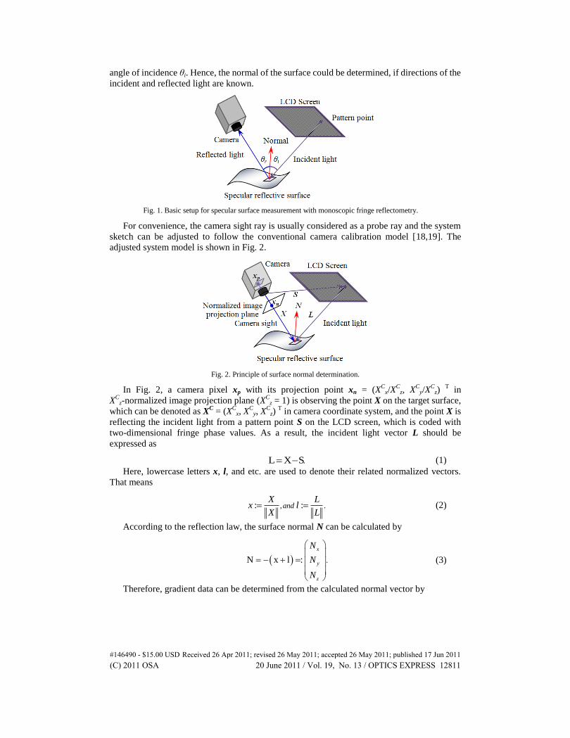
angle of incidence θi. Hence, the normal of the surface could be determined, if directions of the
incident and reflected light are known.
Fig. 1. Basic setup for specular surface measurement with monoscopic fringe reflectometry.
For convenience, the camera sight ray is usually considered as a probe ray and the system
sketch can be adjusted to follow the conventional camera calibration model [18,19]. The
adjusted system model is shown in Fig. 2.
Fig. 2. Principle of surface normal determination.
In Fig. 2, a camera pixel xp with its projection point xn = (XC
x/XC
z, XC
y/XC
z) T in
XC
z-normalized image projection plane (XC
z = 1) is observing the point X on the target surface,
which can be denoted as XC = (X
Cx, X
Cy, X
Cz)
T in camera coordinate system, and the point X is
reflecting the incident light from a pattern point S on the LCD screen, which is coded with
two-dimensional fringe phase values. As a result, the incident light vector L should be
expressed as
.L X S (1)
Here, lowercase letters x, l, and etc. are used to denote their related normalized vectors.
That means
, .: : andX L
x lX L
(2)
According to the reflection law, the surface normal N can be calculated by
.N x l :
x
y
z
N
N
N
(3)
Therefore, gradient data can be determined from the calculated normal vector by
#146490 - $15.00 USD Received 26 Apr 2011; revised 26 May 2011; accepted 26 May 2011; published 17 Jun 2011(C) 2011 OSA 20 June 2011 / Vol. 19, No. 13 / OPTICS EXPRESS 12811
,
, ,1, :
, ,
x
yz
N p x y zz x y
N q x y zN
(4)
where p(x, y, z) and q(x, y, z) are slope values at point X = : (x, y, z) in x-and y-direction,
respectively. Note the point X = (x, y, z) can be both denoted as XW
= (XW
x, XW
y, XW
z) T in real
world coordinate and XC = (X
Cx, X
Cy, X
Cz)
T in camera coordinate.
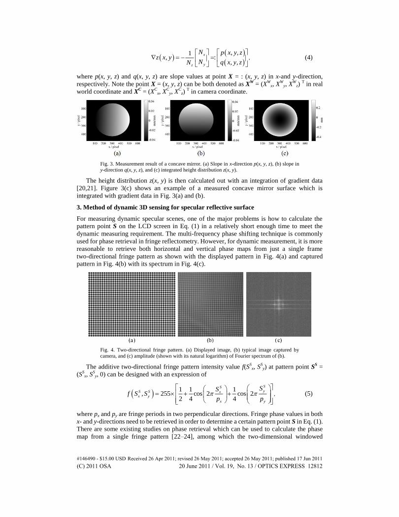
Fig. 3. Measurement result of a concave mirror. (a) Slope in x-direction p(x, y, z), (b) slope in
y-direction q(x, y, z), and (c) integrated height distribution z(x, y).
The height distribution z(x, y) is then calculated out with an integration of gradient data
[20,21]. Figure 3(c) shows an example of a measured concave mirror surface which is
integrated with gradient data in Fig. 3(a) and (b).
3. Method of dynamic 3D sensing for specular reflective surface
For measuring dynamic specular scenes, one of the major problems is how to calculate the
pattern point S on the LCD screen in Eq. (1) in a relatively short enough time to meet the
dynamic measuring requirement. The multi-frequency phase shifting technique is commonly
used for phase retrieval in fringe reflectometry. However, for dynamic measurement, it is more
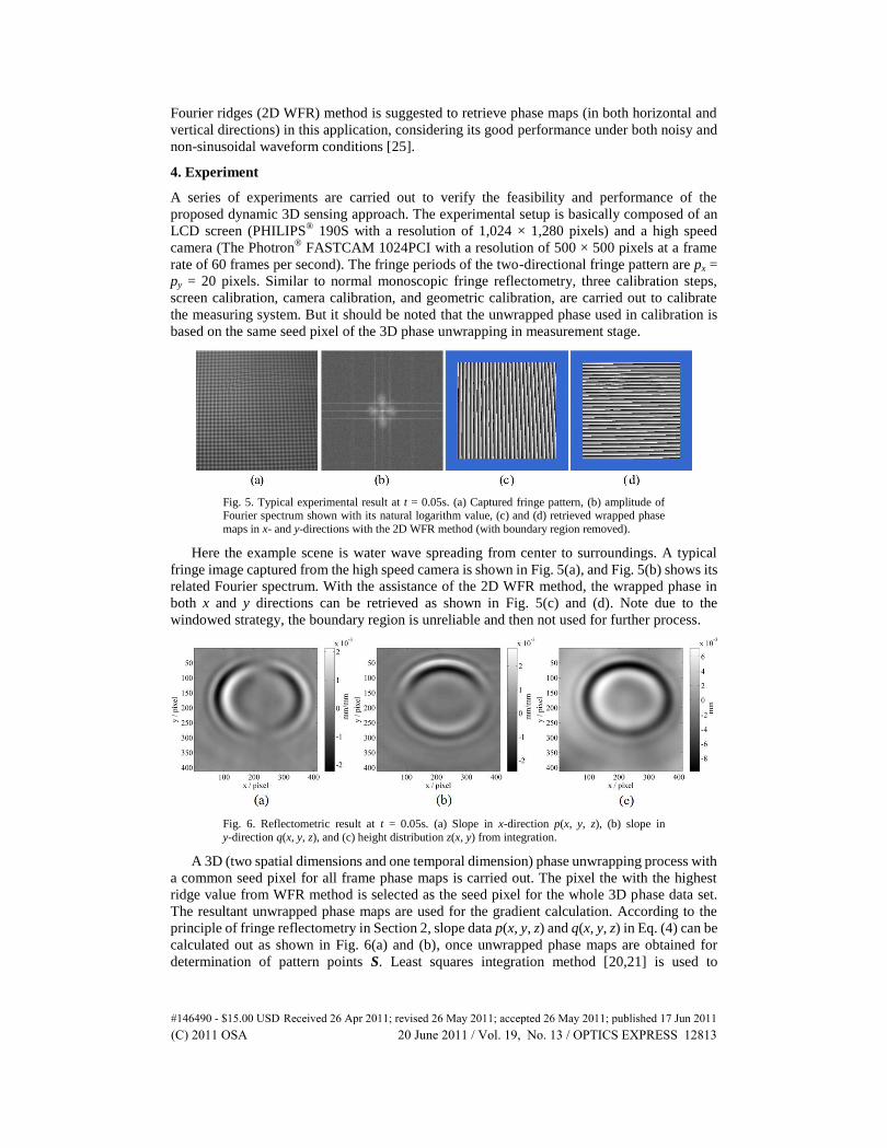
reasonable to retrieve both horizontal and vertical phase maps from just a single frame
two-directional fringe pattern as shown with the displayed pattern in Fig. 4(a) and captured
pattern in Fig. 4(b) with its spectrum in Fig. 4(c).
Fig. 4. Two-directional fringe pattern. (a) Displayed image, (b) typical image captured by
camera, and (c) amplitude (shown with its natural logarithm) of Fourier spectrum of (b).
The additive two-directional fringe pattern intensity value f(SSx, S
Sy) at pattern point S
S =
(SSx, S
Sy, 0) can be designed with an expression of
,1 1 1
, 255 cos 2 cos 22 4 4
SSyS S x
x y
x y
SSf S S
p p
(5)
where px and py are fringe periods in two perpendicular directions. Fringe phase values in both
x- and y-directions need to be retrieved in order to determine a certain pattern point S in Eq. (1).
There are some existing studies on phase retrieval which can be used to calculate the phase
map from a single fringe pattern [22–24], among which the two-dimensional windowed
#146490 - $15.00 USD Received 26 Apr 2011; revised 26 May 2011; accepted 26 May 2011; published 17 Jun 2011(C) 2011 OSA 20 June 2011 / Vol. 19, No. 13 / OPTICS EXPRESS 12812
Fourier ridges (2D WFR) method is suggested to retrieve phase maps (in both horizontal and
vertical directions) in this application, considering its good performance under both noisy and
non-sinusoidal waveform conditions [25].
4. Experiment
A series of experiments are carried out to verify the feasibility and performance of the
proposed dynamic 3D sensing approach. The experimental setup is basically composed of an
LCD screen (PHILIPS® 190S with a resolution of 1,024 × 1,280 pixels) and a high speed
camera (The Photron® FASTCAM 1024PCI with a resolution of 500 × 500 pixels at a frame
rate of 60 frames per second). The fringe periods of the two-directional fringe pattern are px =
py = 20 pixels. Similar to normal monoscopic fringe reflectometry, three calibration steps,
screen calibration, camera calibration, and geometric calibration, are carried out to calibrate
the measuring system. But it should be noted that the unwrapped phase used in calibration is
based on the same seed pixel of the 3D phase unwrapping in measurement stage.
Fig. 5. Typical experimental result at t = 0.05s. (a) Captured fringe pattern, (b) amplitude of Fourier spectrum shown with its natural logarithm value, (c) and (d) retrieved wrapped phase
maps in x- and y-directions with the 2D WFR method (with boundary region removed).
Here the example scene is water wave spreading from center to surroundings. A typical
fringe image captured from the high speed camera is shown in Fig. 5(a), and Fig. 5(b) shows its
related Fourier spectrum. With the assistance of the 2D WFR method, the wrapped phase in
both x and y directions can be retrieved as shown in Fig. 5(c) and (d). Note due to the
windowed strategy, the boundary region is unreliable and then not used for further process.
Fig. 6. Reflectometric result at t = 0.05s. (a) Slope in x-direction p(x, y, z), (b) slope in
y-direction q(x, y, z), and (c) height distribution z(x, y) from integration.
A 3D (two spatial dimensions and one temporal dimension) phase unwrapping process with
a common seed pixel for all frame phase maps is carried out. The pixel the with the highest
ridge value from WFR method is selected as the seed pixel for the whole 3D phase data set.
The resultant unwrapped phase maps are used for the gradient calculation. According to the
principle of fringe reflectometry in Section 2, slope data p(x, y, z) and q(x, y, z) in Eq. (4) can be
calculated out as shown in Fig. 6(a) and (b), once unwrapped phase maps are obtained for
determination of pattern points S. Least squares integration method [20,21] is used to
#146490 - $15.00 USD Received 26 Apr 2011; revised 26 May 2011; accepted 26 May 2011; published 17 Jun 2011(C) 2011 OSA 20 June 2011 / Vol. 19, No. 13 / OPTICS EXPRESS 12813
determine the height variation of water wave as shown in Fig. 6(c). The height variation range
in this experiment is about 20 microns and the field of view in this experiment is around
150mm × 150mm.
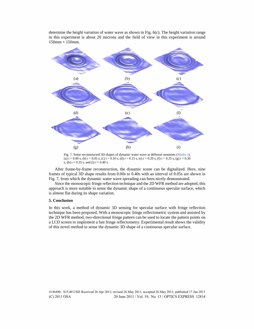
Fig. 7. Some reconstructed 3D shapes of dynamic water wave at different moments (Media 1).
(a) t = 0.00 s, (b) t = 0.05 s, (c) t = 0.10 s, (d) t = 0.15 s, (e) t = 0.20 s, (f) t = 0.25 s, (g) t = 0.30
s, (h) t = 0.35 s, and (i) t = 0.40 s.
After frame-by-frame reconstruction, the dynamic scene can be digitalized. Here, nine
frames of typical 3D shape results from 0.00s to 0.40s with an interval of 0.05s are shown in
Fig. 7, from which the dynamic water wave spreading can been nicely demonstrated.
Since the monoscopic fringe reflection technique and the 2D WFR method are adopted, this
approach is more suitable to sense the dynamic shape of a continuous specular surface, which
is almost flat during its shape variation.
5. Conclusion
In this work, a method of dynamic 3D sensing for specular surface with fringe reflection
technique has been proposed. With a monoscopic fringe reflectometric system and assisted by
the 2D WFR method, two-directional fringe pattern can be used to locate the pattern points on
a LCD screen to implement a fast fringe reflectometry. Experimental result shows the validity
of this novel method to sense the dynamic 3D shape of a continuous specular surface.
#146490 - $15.00 USD Received 26 Apr 2011; revised 26 May 2011; accepted 26 May 2011; published 17 Jun 2011(C) 2011 OSA 20 June 2011 / Vol. 19, No. 13 / OPTICS EXPRESS 12814