Embed Size (px)
Citation preview

Dynamic properties and optical phase conjugation of two-photon pumped ultrashort bluestimulated emission in a chromophore solution
Guang S. He,1,* Hai-Yan Qin,1,3,4 Qingdong Zheng,1 Paras N. Prasad,1 Steffen Jockusch,2 Nicholas J. Turro,2 Marlin Halim,2
Dalibor Sames,2 Hans Ågren,3 and Sailing He4
1Institute for Lasers, Photonics and Biophotonics, Department of Chemistry, State University of New York at Buffalo,Buffalo, New York 14260-3000, USA
2Department of Chemistry, Columbia University, 3000 Broadway, New York, New York 10027, USA3Department of Theoretical Chemistry, Royal Institute of Technology, S-106 91 Stockholm, Sweden4Centre for Optical and Electromagnetic Research, Zhejiang University, Hangzhou 310058, China
�Received 23 October 2007; revised manuscript received 15 November 2007; published 23 January 2008�
The dynamic properties of two-photon pumped blue lasing ��470 nm� in the solution of an organic chro-mophore �2-acetyl-6-�dimethylamino�naphthalene�, excited by �160-fs laser pulses at �775 nm, have beenstudied. Both the forward and backward stimulated emission are enhanced by feedback from the reflection atthe two optical windows of the solution filled cuvette. Under current experimental conditions, the lasingwavelengths in the forward and backward directions were almost the same, but both blueshifted compared tothe fluorescence peak wavelength of the sample solution. The temporal behavior of the lasing output wasrecorded by a high-speed streak camera system. The multipulse structure and spectral properties of the outputlasing are semiquantitatively explained. In addition, excellent optical phase-conjugation properties of thebackward stimulated emission were observed; the aberration influences from an aberrator on the backwardlasing beam were automatically removed.
DOI: 10.1103/PhysRevA.77.013824 PACS number�s�: 42.65.Sf, 32.80.Wr, 42.65.Re, 42.65.Hw
I. INTRODUCTION
Multiphoton pumped �MPP� up-conversion lasing in or-ganic gain media has attracted considerable attention in thepast decade �1–14�. One unique feature of multiphotonpumped stimulated emission is that the pump wavelengthcan be chosen in a suitable infrared �IR� range and the stimu-lated emission generated can be in the visible range. Com-pared to other existing frequency up-conversion techniques�such as second- or third-harmonic generation�, MPP lasingexhibits the advantage of easy tunability and no phase-matching requirement. For some applications, such as opticaldata storage and photolithography, a shorter lasing wave-length is more desirable. So far, most reported MPP lasingwavelengths were in the 490–620-nm spectral range.
In this work, we report experimental studies of two-photon pumped �2PP� blue lasing at a wavelength of�470 nm from a chromophore solution, excited by femto-second IR laser pulses. One feature of this work is to inves-tigate the role of feedback from the reflection at the twowindows of the sample cuvette. It is found that the feedbackcan enhance the lasing output and affect the lasing dynamicbehavior. Another feature is that the lasing wavelengths areshorter than the peak fluorescence wavelength. This is ex-plained by the transient behavior of the peak gain position.
In addition, experimental results of optical phase-conjugation property for the backward lasing beam are alsopresented. This property indicates that a good optical qualitylasing beam can be obtained from a poor quality lasing me-dium or even after passing through a highly aberrated propa-gation medium.
II. OPTICAL PROPERTIES OF A LASING MEDIUM
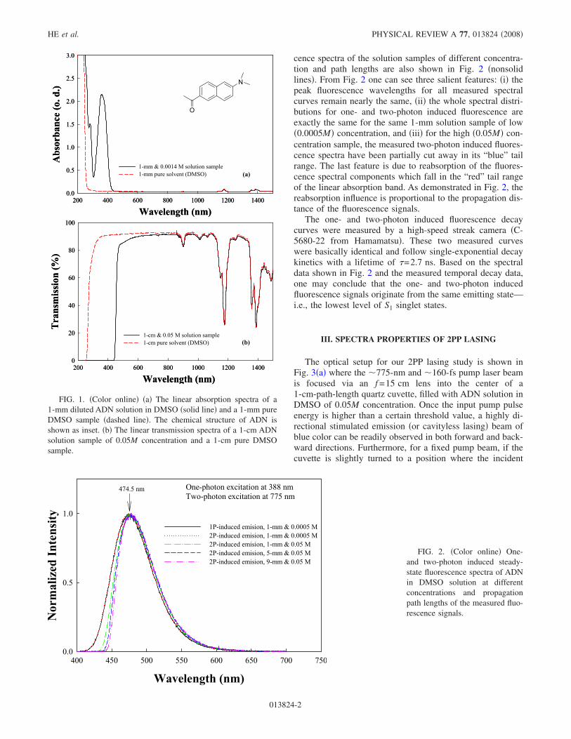
The 2PP lasing medium in this study is an organic chro-mophore, 2-acetyl-6-�dimethylamino�naphthalene �ADN� indimethyl sulfoxide �DMSO� solution. The chemical structureof ADN is shown at the top of Fig. 1�a�. This chromophorewas originally designed as fluorogenic probe for biologicalsystems using two-photon excitation �15�, and the synthesisof ADN was described previously �16�.
The measured linear absorption spectra of a 1-mm-thickdilute solution sample of ADN and pure solvent �DMSO� ofthe same path length are shown in Fig. 1�a�, respectively,where ADN shows a linear absorption peak at �360 nm witha bandwidth of �70 nm. Shown in Fig. 1�b� are the trans-mission spectra of a 1-cm-path-length solution sample of0.05M concentration and a pure DMSO sample of the samepath length. From Fig. 1�b� one can see that there is negli-gible linear absorption for the solute in the entire spectralrange from 600 to 1500 nm, although there are several dis-crete IR absorption bands attributed to the solvent.
A Ti:sapphire laser oscillator-amplifier system �CPA-2010from Clark-MXR� was utilized as a two-photon excitationsource, which generated pulses at 775 nm of 160 fs pulselength. This nearly linearly polarized laser beam has a beamsize of �4 mm, a divergence angle of 0.22 mrad, and a rep-etition rate of 1 kHz.
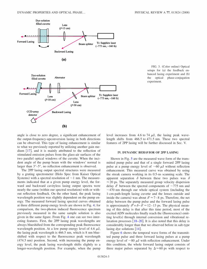
The one-photon induced fluorescence spectrum from a1-mm ADN solution sample of low �0.0005M� concentrationis shown in Fig. 2 �solid line�, which was excited at 388 nmby using second-harmonic generation of the 775-nm laserbeam. The peak fluorescence wavelength is located at�475 nm, and the fluorescence spectral bandwidth �fullwidth at half maximum� is �70 nm. With excitation at775 nm, the two-photon absorption �2PA� induced fluores-*[email protected]
PHYSICAL REVIEW A 77, 013824 �2008�
1050-2947/2008/77�1�/013824�10� ©2008 The American Physical Society013824-1
cence spectra of the solution samples of different concentra-tion and path lengths are also shown in Fig. 2 �nonsolidlines�. From Fig. 2 one can see three salient features: �i� thepeak fluorescence wavelengths for all measured spectralcurves remain nearly the same, �ii� the whole spectral distri-butions for one- and two-photon induced fluorescence areexactly the same for the same 1-mm solution sample of low�0.0005M� concentration, and �iii� for the high �0.05M� con-centration sample, the measured two-photon induced fluores-cence spectra have been partially cut away in its “blue” tailrange. The last feature is due to reabsorption of the fluores-cence spectral components which fall in the “red” tail rangeof the linear absorption band. As demonstrated in Fig. 2, thereabsorption influence is proportional to the propagation dis-tance of the fluorescence signals.
The one- and two-photon induced fluorescence decaycurves were measured by a high-speed streak camera �C-5680-22 from Hamamatsu�. These two measured curveswere basically identical and follow single-exponential decaykinetics with a lifetime of �=2.7 ns. Based on the spectraldata shown in Fig. 2 and the measured temporal decay data,one may conclude that the one- and two-photon inducedfluorescence signals originate from the same emitting state—i.e., the lowest level of S1 singlet states.
III. SPECTRA PROPERTIES OF 2PP LASING
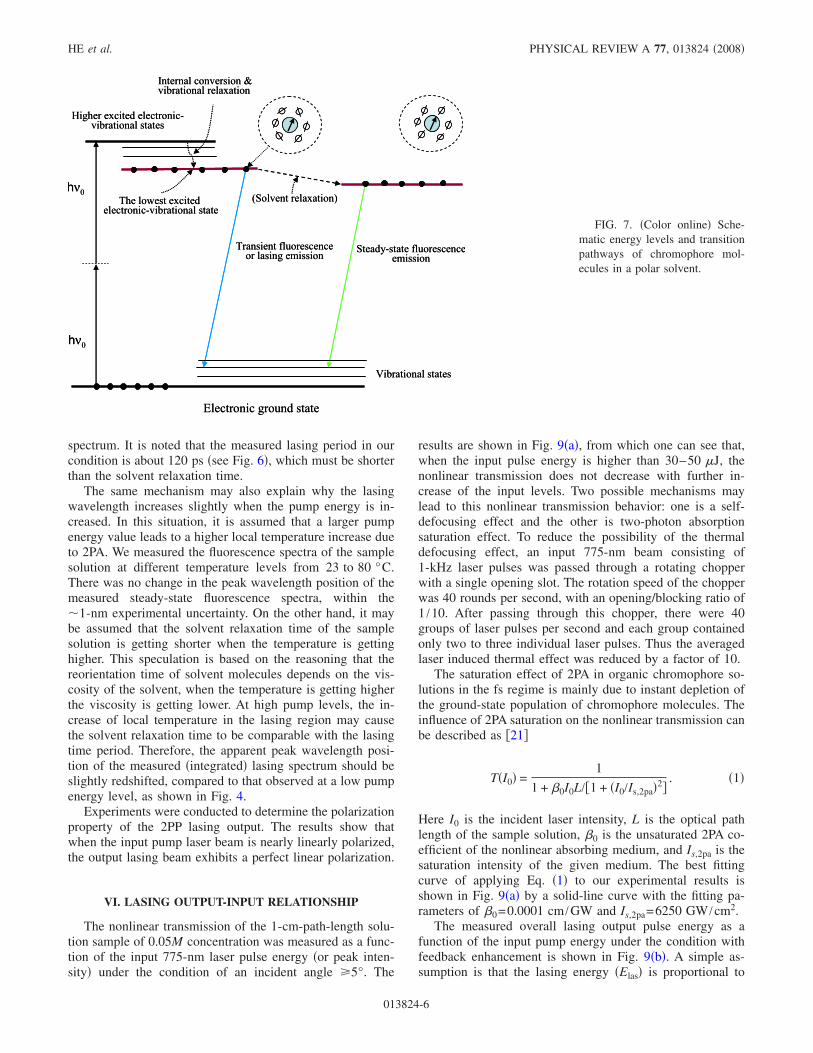
The optical setup for our 2PP lasing study is shown inFig. 3�a� where the �775-nm and �160-fs pump laser beamis focused via an f =15 cm lens into the center of a1-cm-path-length quartz cuvette, filled with ADN solution inDMSO of 0.05M concentration. Once the input pump pulseenergy is higher than a certain threshold value, a highly di-rectional stimulated emission �or cavityless lasing� beam ofblue color can be readily observed in both forward and back-ward directions. Furthermore, for a fixed pump beam, if thecuvette is slightly turned to a position where the incident
Wavelength (nm)200 400 600 800 1000 1200 1400
Absorbance(o.d.)
0.0
0.5
1.0
1.5
2.0
2.5
3.0
1-mm & 0.0014 M solution sample1-mm pure solvent (DMSO)
Wavelength (nm)200 400 600 800 1000 1200 1400
Transmission(%)
0
20
40
60
80
100
1-cm & 0.05 M solution sample1-cm pure solvent (DMSO)
(a)
(b)
N
O
Wavelength (nm)200 400 600 800 1000 1200 1400
Absorbance(o.d.)
0.0
0.5
1.0
1.5
2.0
2.5
3.0
1-mm & 0.0014 M solution sample1-mm pure solvent (DMSO)
Wavelength (nm)200 400 600 800 1000 1200 1400
Transmission(%)
0
20
40
60
80
100
1-cm & 0.05 M solution sample1-cm pure solvent (DMSO)
(a)
(b)
N
O
FIG. 1. �Color online� �a� The linear absorption spectra of a1-mm diluted ADN solution in DMSO �solid line� and a 1-mm pureDMSO sample �dashed line�. The chemical structure of ADN isshown as inset. �b� The linear transmission spectra of a 1-cm ADNsolution sample of 0.05M concentration and a 1-cm pure DMSOsample.
Wavelength (nm)400 450 500 550 600 650 700 750
NormalizedIntensity
0.0
0.5
1.01P-induced emision, 1-mm & 0.0005 M2P-induced emision, 1-mm & 0.0005 M2P-induced emision, 1-mm & 0.05 M2P-induced emision, 5-mm & 0.05 M2P-induced emision, 9-mm & 0.05 M
One-photon excitation at 388 nmTwo-photon excitation at 775 nm
474.5 nm
FIG. 2. �Color online� One-and two-photon induced steady-state fluorescence spectra of ADNin DMSO solution at differentconcentrations and propagationpath lengths of the measured fluo-rescence signals.
HE et al. PHYSICAL REVIEW A 77, 013824 �2008�
013824-2
angle is close to zero degree, a significant enhancement ofthe output-frequency-upconversion lasing in both directionscan be observed. This type of lasing enhancement is similarto what we previously reported by utilizing another gain me-dium �17�, and it is mainly attributed to the reflection ofstimulated emission pulses from the glass-air surfaces of thetwo parallel optical windows of the cuvette. When the inci-dent angle of the pump beam with the windows’ normal islarger than 3°–5°, no reflection enhancement is observed.
The 2PP lasing output spectral structures were measuredby a grating spectrometer �Holo Spec from Kaiser OpticalSystems� with a spectral resolution of �1 nm. The measure-ments indicated that at a given pump energy level, the for-ward and backward cavityless lasing output spectra werenearly the same �within our spectral resolution� with or with-out reflection feedback. On the other hand, the peak lasingwavelength position was slightly dependent on the pump en-ergy. The measured forward lasing spectral curves obtainedat three different pump energy levels are shown in Fig. 4; forcomparison, the two-photon induced fluorescence spectrumpreviously measured in the same sample solution is alsogiven in the same figure. From Fig. 4 one can see two inter-esting features. First, the 2PP lasing peak wavelengths arealways blueshifted from the corresponding peak fluorescencewavelength position. At a low pump energy level of 4.6 �J,the lasing peak wavelength is 466.5 nm, which is 8 nm blue-shifted with respect to the fluorescence peak wavelength�474.5 nm� position. Second, with increasing the pump en-ergy level, the peak lasing wavelength shifts slightly to alonger-wavelength position. For example, when the pump
level increases from 4.6 to 74 �J, the lasing peak wave-length shifts from 466.5 to 471.5 nm. These two spectralfeatures of 2PP lasing will be further discussed in Sec. V.
IV. DYNAMIC BEHAVIOR OF 2PP LASING
Shown in Fig. 5 are the measured wave form of the trans-mitted pump pulse and that of a single forward 2PP lasingpulse at a pump energy level of �60 �J without reflectionenhancement. This measured curve was obtained by usingthe streak camera working in its 0.5-ns scanning scale. Theapparent separation � between these two pulses was ��20 ps. The separately measured group velocity dispersiondelay �� between the spectral components of �775 nm and�470 nm through our whole optical system �including the1-cm-path-length lasing cuvette and the lenses outside andinside the camera� was about ���7–8 ps. Therefore, the netdelay between the pump pulse and the forward lasing pulseis approximately ��=�−���12–13 ps. The physical mean-ing of this delay is that after this time period, most of theexcited ADN molecules finally reach the �fluorescence� emit-ting level�s� through internal conversion and vibrational re-laxation processes �18–20�. It is also noted that this delay isconsiderably longer than that we observed before in salt-typelasing dye solutions �14�.
Figure 6 shows the temporal wave forms of the transmit-ted pump pulse and three forward lasing pulses at a pumpenergy level of �80 �J with reflection enhancement. Underthis condition, the whole forward lasing output consists ofthree major pulses separated by ��60 ps with respect to
Ti: Sapphire laser(~775 nm, ~160 fs)
Beam splitter
Dye-solutionfilled cuvette
CCD-arraydetector
Lens(f=10 cm)
Lens(f=50 cm)
(a)
(b)
Aberrator
Forward Lasing
Backward Lasing
Ti: Sapphire laser(~775 nm, ~160 fs)
Beam splitter
Dye-solutionfilled cuvette Lens
(f=15 cm)
Forward Lasing
Backward Lasing
Ti: Sapphire laser(~775 nm, ~160 fs)
Beam splitter
Dye-solutionfilled cuvette
CCD-arraydetector
Lens(f=10 cm)
Lens(f=50 cm)
(a)
(b)
Aberrator
Forward Lasing
Backward Lasing
Ti: Sapphire laser(~775 nm, ~160 fs)
Beam splitter
Dye-solutionfilled cuvette Lens
(f=15 cm)
Forward Lasing
Backward Lasing
FIG. 3. �Color online� Opticalsetups for �a� the feedback en-hanced lasing experiment and �b�the optical phase-conjugationexperiment.
DYNAMIC PROPERTIES AND OPTICAL PHASE… PHYSICAL REVIEW A 77, 013824 �2008�
013824-3

each other. Considering the 1-cm optical path length of thecuvette and the thickness of the optical window of 1 mm, theround-trip time of the photons within the cavity formed bythe two window-air surfaces is �120 ps. The formation ofthe multipulse structure of the forward lasing output can beclearly explained by means of the inset in Fig. 6, where thepump pulse is focused in the center of the gain medium andboth the initial forward and backward stimulated emissionsignals start from this point. The forward initial stimulatedemission is further amplified by passing through half of theeffective gain length and finally forms the first lasing pulsethat is the same as what we observed in Fig. 5 without feed-back enhancement. Similarly, the backward initial stimulatedemission experiences the same amplification passing throughhalf of the cuvette’s path length and is partially reflected atthe glass-air surface of the entrance window. The reflectedbackward lasing signal will get further amplification by pass-ing through the whole effective gain length and finally formthe second output lasing pulse. At the same time, the par-
tially reflected first forward lasing pulse at the exit windowand sequentially at the entrance window will get a doublepath-length gain and finally form the third output laser pulse.The above explanation is acceptable, if we assume that thepump pulse generated peak gain �population inversion� canlast longer than 150–200 ps.
There is one issue that should be discussed: i.e., why themeasured lasing lasting time �150–200 ps� is much shorterthan the fluorescence lifetime ��2.7 ns�. In this case, wemay consider two factors: one is the dynamic curve of thegain medium, and the second is the threshold requirement forgenerating lasing. In general, the dynamic gain curve for again medium is determined by the population inversion de-cay curve in time scale, and the latter can be approximatelyrecognized as the fluorescence decay curve without consid-ering the depletion effect. Due to the threshold requirement,only the top section of the exponential decay curve can pro-vide high enough gain over a certain propagation length �ef-fective gain length or focal depth of the pump beam� to over-
Wavelength (nm)420 440 460 480 500 520 540 560 580 600
NormalizedIntensity
0.0
0.5
1.0 2P-induced fluorescencelasing at 4.6-μJ pump levellasing at 28-μJ pump levellasing at 74-μJ pump level
Two-photon excitation at 775 nm466.5 nm 471.5 nm
468.5 nm
474.5 nm
Wavelength (nm)420 440 460 480 500 520 540 560 580 600
NormalizedIntensity
0.0
0.5
1.0 2P-induced fluorescencelasing at 4.6-μJ pump levellasing at 28-μJ pump levellasing at 74-μJ pump level
Two-photon excitation at 775 nm466.5 nm 471.5 nm
468.5 nm
474.5 nm
FIG. 4. �Color online� 2PP for-ward lasing spectra at three differ-ent pump energy levels and thecorresponding fluorescence spec-trum of ADN �0.05M� in DMSO.
Time (ps)-100 0 100 200 300 400
NormalizedIntensity
0.0
0.5
1.0
~20 ps
2P pumped forward lasing without feedback enhancement
Transmittedpump pulse
Forwardlasing pulse
FIG. 5. Temporal wave formsof the transmitted pump pulse andthe forward lasing pulse withoutfeedback enhancement.
HE et al. PHYSICAL REVIEW A 77, 013824 �2008�
013824-4

come the losses caused by various attenuation mechanisms.This is the first reason why the lasing time period is muchshorter than the fluorescence lifetime of the gain mediumunder ultrashort laser pump condition. The second reason isthat once the lasing is taking place near the top position ofthe exponential decaying curve of gain or population inver-sion, the photon simulated amplification will expedite thedepletion of population inversion of the gain medium, whichleads to further shortening of the effective gain decay incomparison with the normal fluorescence decay curve.
V. SOME PHYSICAL EXPLANATIONS OF THE LASINGSPECTRAL PROPERTIES
As described in Sec. III and shown by Fig. 4, there aretwo salient features of 2PP lasing spectral behavior: one isthe blueshift of the lasing peak wavelength with respect tothe fluorescence peak wavelength; the other is a slight red-shift of the lasing peak wavelength with the increase ofpump energy. Both of these two features can be qualitativelyexplained by the so-called solvent relaxation mechanism,which commonly occurs in organic chromophore solutionswhen a polar solvent �such as DMSO� is involved �18–20�.The influence of solvent relaxation on the transient fluores-cence emission spectral structure can be well understood bymeans of schematic illustration shown in Fig. 7. Withoutoptical excitation, most chromophore molecules stay in theirlowest vibrational level of the S0 ground electronic state,while each of them exhibits an equilibrium interaction withthe surrounding solvent molecules. After applying an ul-trashort laser pulse, some chromophore molecules are ex-cited to a vibrational level of higher electronic states andthen rapidly relaxed to the lowest vibrational level of the S1singlet state, from which the fluorescence emission can beobserved with a relatively long lifetime �usually in the ns
regime�. For those excited chromophore molecules justreaching the fluorescence emitting level, the pump field in-duced molecular dipole moment vector of an excited chro-mophore molecule is changed in magnitude and/or direction,compared to those of nonexcited molecules. In this case, theexcited chromophore molecule has a tendency to reorientatethe surrounding solvent molecules to keep a minimum freeenergy of the cage consisting of this excited chromophoremolecule and surrounding solvent molecules and to lowertheir interaction energy. This solvent relaxation may take atime period of several tens to several hundreds of picosec-onds depending on specific solutes, solvents, and other con-ditions �such as temperature�.
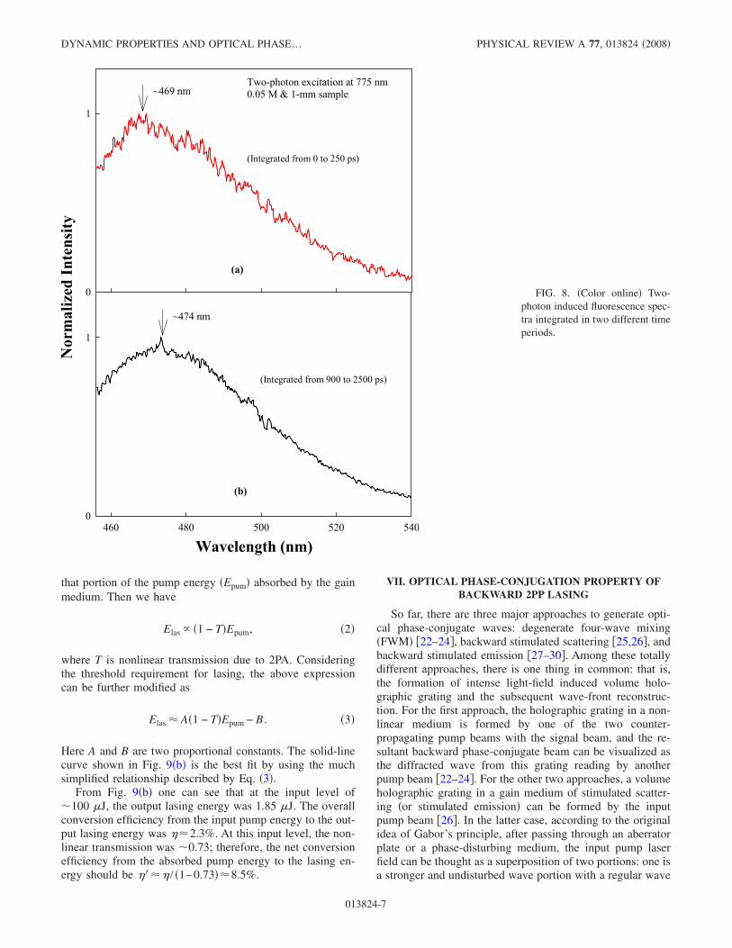
According to this explanation, at the beginning of the pro-cess, the fluorescence emission peak wavelength should beshorter than that at the end of process. Measuring the time-resolved fluorescence spectral structure, one may observethat the peak fluorescence emission wavelength will continu-ously shift toward the longer-wavelength position during thetime period of solvent relaxation. For this purpose, we mea-sured the time-resolved fluorescence spectral change by us-ing the streak camera in conjunction with a grating spectrom-eter. Shown in Fig. 8�a� is the measured fluorescence spectraldistribution integrated in a time period of 250 ps from thestarting point of fluorescence emission, whereas shown inFig. 8�b� is the spectral distribution integrated in a periodfrom 900 to 2500 ps. In the former case, the peak emissionwavelength is �469 nm which is close to the lasing wave-lengths, whereas in the latter case, the peak emission wave-length is �474 nm that is close to the steady-state fluores-cence peak wavelength. Usually, it is assumed that the peaklasing wavelength position is determined by the transientpeak fluorescence wavelength position; therefore, it can beexplained why the observed lasing wavelengths are shorterthan the peak wavelength of the steady-state fluorescence
Time (ps)-100 0 100 200 300 400
NormalizedIntensity
0
1
~20 ps~60 ps~60 ps
2P pumped forward lasing output
Transmittedpump pulse
1st lasing pulse
2nd lasing pulse
3rd lasing pulse
Transmittedpump pulse1st lasing pulse2nd lasing pulse3rd lasing pulse
Time (ps)-100 0 100 200 300 400
NormalizedIntensity
0
1
~20 ps~60 ps~60 ps
2P pumped forward lasing output
Transmittedpump pulse
1st lasing pulse
2nd lasing pulse
3rd lasing pulse
Transmittedpump pulse1st lasing pulse2nd lasing pulse3rd lasing pulse
Transmittedpump pulse1st lasing pulse2nd lasing pulse3rd lasing pulse
FIG. 6. �Color online� Tempo-ral wave forms of the transmittedpump pulse and the forwardlasing pulses with feedbackenhancement.
DYNAMIC PROPERTIES AND OPTICAL PHASE… PHYSICAL REVIEW A 77, 013824 �2008�
013824-5
spectrum. It is noted that the measured lasing period in ourcondition is about 120 ps �see Fig. 6�, which must be shorterthan the solvent relaxation time.
The same mechanism may also explain why the lasingwavelength increases slightly when the pump energy is in-creased. In this situation, it is assumed that a larger pumpenergy value leads to a higher local temperature increase dueto 2PA. We measured the fluorescence spectra of the samplesolution at different temperature levels from 23 to 80 °C.There was no change in the peak wavelength position of themeasured steady-state fluorescence spectra, within the�1-nm experimental uncertainty. On the other hand, it maybe assumed that the solvent relaxation time of the samplesolution is getting shorter when the temperature is gettinghigher. This speculation is based on the reasoning that thereorientation time of solvent molecules depends on the vis-cosity of the solvent, when the temperature is getting higherthe viscosity is getting lower. At high pump levels, the in-crease of local temperature in the lasing region may causethe solvent relaxation time to be comparable with the lasingtime period. Therefore, the apparent peak wavelength posi-tion of the measured �integrated� lasing spectrum should beslightly redshifted, compared to that observed at a low pumpenergy level, as shown in Fig. 4.
Experiments were conducted to determine the polarizationproperty of the 2PP lasing output. The results show thatwhen the input pump laser beam is nearly linearly polarized,the output lasing beam exhibits a perfect linear polarization.
VI. LASING OUTPUT-INPUT RELATIONSHIP
The nonlinear transmission of the 1-cm-path-length solu-tion sample of 0.05M concentration was measured as a func-tion of the input 775-nm laser pulse energy �or peak inten-sity� under the condition of an incident angle �5°. The
results are shown in Fig. 9�a�, from which one can see that,when the input pulse energy is higher than 30–50 �J, thenonlinear transmission does not decrease with further in-crease of the input levels. Two possible mechanisms maylead to this nonlinear transmission behavior: one is a self-defocusing effect and the other is two-photon absorptionsaturation effect. To reduce the possibility of the thermaldefocusing effect, an input 775-nm beam consisting of1-kHz laser pulses was passed through a rotating chopperwith a single opening slot. The rotation speed of the chopperwas 40 rounds per second, with an opening/blocking ratio of1 /10. After passing through this chopper, there were 40groups of laser pulses per second and each group containedonly two to three individual laser pulses. Thus the averagedlaser induced thermal effect was reduced by a factor of 10.
The saturation effect of 2PA in organic chromophore so-lutions in the fs regime is mainly due to instant depletion ofthe ground-state population of chromophore molecules. Theinfluence of 2PA saturation on the nonlinear transmission canbe described as �21�
T�I0� =1
1 + �0I0L/�1 + �I0/Is,2pa�2�. �1�
Here I0 is the incident laser intensity, L is the optical pathlength of the sample solution, �0 is the unsaturated 2PA co-efficient of the nonlinear absorbing medium, and Is,2pa is thesaturation intensity of the given medium. The best fittingcurve of applying Eq. �1� to our experimental results isshown in Fig. 9�a� by a solid-line curve with the fitting pa-rameters of �0=0.0001 cm /GW and Is,2pa=6250 GW /cm2.
The measured overall lasing output pulse energy as afunction of the input pump energy under the condition withfeedback enhancement is shown in Fig. 9�b�. A simple as-sumption is that the lasing energy �Elas� is proportional to
Electronic ground state
Higher excited electronic-vibrational states
Internal conversion &vibrational relaxation
(Solvent relaxation)The lowest excitedelectronic-vibrational state
hν0
hν0
Vibrational states
Steady-state fluorescenceemission
Transient fluorescenceor lasing emission
Electronic ground state
Higher excited electronic-vibrational states
Internal conversion &vibrational relaxation
(Solvent relaxation)The lowest excitedelectronic-vibrational state
hν0
hν0
Vibrational states
Steady-state fluorescenceemission
Transient fluorescenceor lasing emission
FIG. 7. �Color online� Sche-matic energy levels and transitionpathways of chromophore mol-ecules in a polar solvent.
HE et al. PHYSICAL REVIEW A 77, 013824 �2008�
013824-6
that portion of the pump energy �Epum� absorbed by the gainmedium. Then we have
Elas � �1 − T�Epum, �2�
where T is nonlinear transmission due to 2PA. Consideringthe threshold requirement for lasing, the above expressioncan be further modified as
Elas � A�1 − T�Epum − B . �3�
Here A and B are two proportional constants. The solid-linecurve shown in Fig. 9�b� is the best fit by using the muchsimplified relationship described by Eq. �3�.
From Fig. 9�b� one can see that at the input level of�100 �J, the output lasing energy was 1.85 �J. The overallconversion efficiency from the input pump energy to the out-put lasing energy was ��2.3%. At this input level, the non-linear transmission was �0.73; therefore, the net conversionefficiency from the absorbed pump energy to the lasing en-ergy should be ���� / �1–0.73��8.5%.
VII. OPTICAL PHASE-CONJUGATION PROPERTY OFBACKWARD 2PP LASING
So far, there are three major approaches to generate opti-cal phase-conjugate waves: degenerate four-wave mixing�FWM� �22–24�, backward stimulated scattering �25,26�, andbackward stimulated emission �27–30�. Among these totallydifferent approaches, there is one thing in common: that is,the formation of intense light-field induced volume holo-graphic grating and the subsequent wave-front reconstruc-tion. For the first approach, the holographic grating in a non-linear medium is formed by one of the two counter-propagating pump beams with the signal beam, and the re-sultant backward phase-conjugate beam can be visualized asthe diffracted wave from this grating reading by anotherpump beam �22–24�. For the other two approaches, a volumeholographic grating in a gain medium of stimulated scatter-ing �or stimulated emission� can be formed by the inputpump beam �26�. In the latter case, according to the originalidea of Gabor’s principle, after passing through an aberratorplate or a phase-disturbing medium, the input pump laserfield can be thought as a superposition of two portions: one isa stronger and undisturbed wave portion with a regular wave
NormalizedIntensity
0
1
Two-photon excitation at 775 nm0.05 M & 1-mm sample
Wavelength (nm)460 480 500 520 540
0
1
~469 nm
~474 nm
(Integrated from 0 to 250 ps)
(Integrated from 900 to 2500 ps)
(a)
(b)
FIG. 8. �Color online� Two-photon induced fluorescence spec-tra integrated in two different timeperiods.
DYNAMIC PROPERTIES AND OPTICAL PHASE… PHYSICAL REVIEW A 77, 013824 �2008�
013824-7

front, and the other is a weaker and disturbed wave portioncarrying aberration influences. These two portions of thepump field interfere with each other and lead to a character-istic three-dimensional and fluctuated intensity distributioninside the gain medium. Since there is a nonlinear refractive-index change depending on the local pump laser intensity, aholographic phase grating is formed �27�.
In two-photon pumped lasing case, once a pump fieldinduced holographic grating has been formed inside the gainmedium and the intensity level of the undisturbed pump por-tion is higher than a certain threshold value, an initial back-ward stimulated emission wave can be generated at a newfrequency with a regular wave front. During the propagationof this backward wave through the grating region, anotherdiffracted wave at the same frequency is created with a wavefront resembling the disturbed pump portion. In this sense, itis a nondegenerate and quasicollinear FWM process. The
optical phase-conjugation property of the backward 2PP las-ing beam has already been proved in the ns regime �28,29�.Now we further report the same type of optical phase-conjugation property of the backward stimulated emissiongenerated by fs-laser pump pulses.
To assess the optical phase conjugation property of thebackward stimulated, an optical layout design shown in Fig.3�b� is employed. In this case, the pump laser beam wasfocused by an f =10 cm lens into the center of the gain cu-vette with an incident angle �5° to avoid the reflection in-fluence from the windows. Between the focusing lens andthe beam splitter a removable aberrator was placed. The ab-errator was a 1-mm-thick glass slide �model No. 2947 fromCorning� corroded in a diluted hydrofluoric acid. The back-ward stimulated emission output beams was passing throughan f =50 cm lens and focused on the surface of a charge-coupled-device �CCD� array detector. From the spot size of
Input Pulse Energy (µJ)0 20 40 60 80 100 120 140 160 180
OutputLasingEnergy( µJ)
0
1
2
3
4
Input Pulse Energy (µµJ)0 20 40 60 80 100 120 140 160 180
NonlinearTransmission
0.0
0.2
0.4
0.6
0.8
1.0
0 3000 6000 9000 12000 15000 18000Input Pulse Intensity (GW/cm2)
(a)
(b)
Fitting parameters: β0=0.0001 cm/GW; Is,2pa=8250 GW/cm2
Input: 775 nm, 160 fs; 1-cm solution of 0.05 M
Input: 775 nm, 160 fs; 1-cm solution of 0.05 MWith feedback enhancement
FIG. 9. �a� Measured nonlineartransmission versus the inputpulse energy and intensity. �b�Output lasing energy versus theinput pump energy. The solid-linecurves are the best-fitting curvesgiven by Eqs. �1� and �3�,respectively.
HE et al. PHYSICAL REVIEW A 77, 013824 �2008�
013824-8
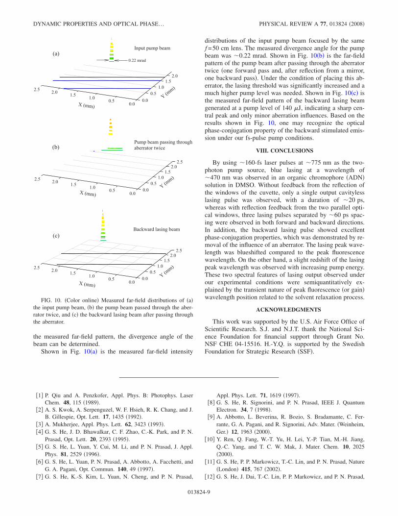
the measured far-field pattern, the divergence angle of thebeam can be determined.
Shown in Fig. 10�a� is the measured far-field intensity
distributions of the input pump beam focused by the samef =50 cm lens. The measured divergence angle for the pumpbeam was �0.22 mrad. Shown in Fig. 10�b� is the far-fieldpattern of the pump beam after passing through the aberratortwice �one forward pass and, after reflection from a mirror,one backward pass�. Under the condition of placing this ab-errator, the lasing threshold was significantly increased and amuch higher pump level was needed. Shown in Fig. 10�c� isthe measured far-field pattern of the backward lasing beamgenerated at a pump level of 140 �J, indicating a sharp cen-tral peak and only minor aberration influences. Based on theresults shown in Fig. 10, one may recognize the opticalphase-conjugation property of the backward stimulated emis-sion under our fs-pulse pump conditions.
VIII. CONCLUSIONS
By using �160-fs laser pulses at �775 nm as the two-photon pump source, blue lasing at a wavelength of�470 nm was observed in an organic chromophore �ADN�solution in DMSO. Without feedback from the reflection ofthe windows of the cuvette, only a single output cavitylesslasing pulse was observed, with a duration of �20 ps,whereas with reflection feedback from the two parallel opti-cal windows, three lasing pulses separated by �60 ps spac-ing were observed in both forward and backward directions.In addition, the backward lasing pulse showed excellentphase-conjugation properties, which was demonstrated by re-moval of the influence of an aberrator. The lasing peak wave-length was blueshifted compared to the peak fluorescencewavelength. On the other hand, a slight redshift of the lasingpeak wavelength was observed with increasing pump energy.These two spectral features of lasing output observed underour experimental conditions were semiquantitatively ex-plained by the transient nature of peak fluorescence �or gain�wavelength position related to the solvent relaxation process.
ACKNOWLEDGMENTS
This work was supported by the U.S. Air Force Office ofScientific Research. S.J. and N.J.T. thank the National Sci-ence Foundation for financial support through Grant No.NSF CHE 04-15516. H.-Y.Q. is supported by the SwedishFoundation for Strategic Research �SSF�.
�1� P. Qiu and A. Penzkofer, Appl. Phys. B: Photophys. LaserChem. 48, 115 �1989�.
�2� A. S. Kwok, A. Serpenguzel, W. F. Hsieh, R. K. Chang, and J.B. Gillespie, Opt. Lett. 17, 1435 �1992�.
�3� A. Mukherjee, Appl. Phys. Lett. 62, 3423 �1993�.�4� G. S. He, J. D. Bhawalkar, C. F. Zhao, C.-K. Park, and P. N.
Prasad, Opt. Lett. 20, 2393 �1995�.�5� G. S. He, L. Yuan, Y. Cui, M. Li, and P. N. Prasad, J. Appl.
Phys. 81, 2529 �1996�.�6� G. S. He, L. Yuan, P. N. Prasad, A. Abbotto, A. Facchetti, and
G. A. Pagani, Opt. Commun. 140, 49 �1997�.�7� G. S. He, K.-S. Kim, L. Yuan, N. Cheng, and P. N. Prasad,
Appl. Phys. Lett. 71, 1619 �1997�.�8� G. S. He, R. Signorini, and P. N. Prasad, IEEE J. Quantum
Electron. 34, 7 �1998�.�9� A. Abbotto, L. Beverina, R. Bozio, S. Bradamante, C. Fer-
rante, G. A. Pagani, and R. Signorini, Adv. Mater. �Weinheim,Ger.� 12, 1963 �2000�.
�10� Y. Ren, Q. Fang, W.-T. Yu, H. Lei, Y.-P. Tian, M.-H. Jiang,Q.-C. Yang, and T. C. W. Mak, J. Mater. Chem. 10, 2025�2000�.
�11� G. S. He, P. P. Markowicz, T.-C. Lin, and P. N. Prasad, Nature�London� 415, 767 �2002�.
�12� G. S. He, J. Dai, T.-C. Lin, P. P. Markowicz, and P. N. Prasad,
(c)
0.00.51.01.52.02.5
0.00.51.01.52.02.5
Y (mm)
X (mm)
(b)
0.00.51.01.52.02.5
0.00.51.01.52.02.5
Y (mm)
X (mm)
Backward lasing beam
Pump beam passing throughaberrator twice
0.00.5
1.01.52.0
0.00.51.01.52.02.5
Y (mm)
X (mm)
(a)Input pump beam
0.22 mrad
FIG. 10. �Color online� Measured far-field distributions of �a�the input pump beam, �b� the pump beam passed through the aber-rator twice, and �c� the backward lasing beam after passing throughthe aberrator.
DYNAMIC PROPERTIES AND OPTICAL PHASE… PHYSICAL REVIEW A 77, 013824 �2008�
013824-9
Opt. Lett. 28, 983 �2003�.�13� C. Ye, J. Wang, and D. Lo, Appl. Phys. B: Lasers Opt. 78, 539
�2004�.�14� G. S. He, T.-C. Lin, S.-J. Chung, Q. Zheng, C. Lu, Y. Cui, and
P. N. Prasad, J. Opt. Soc. Am. B 22, 2219 �2005�.�15� S. Jockusch, Q. Zheng, G. S. He, H. E. Pudavar, D. J. Yee, V.
Balsanek, M. Halim, D. Sames, P. N. Prasad, and N. J. Turro,J. Phys. Chem. C 111, 8872 �2007�.
�16� D. J. Yee, V. Balsanek, and D. Sames, J. Am. Chem. Soc. 126,2282 �2004�.
�17� G. S. He, Q. Zheng, P. N. Prasad, and J. G. Grote, Opt. Lett.31, 359 �2006�.
�18� �a� G. S. He, C. Lu, Q. Zheng, A. Baev, M. Samoc, and P. N.Prasad, Phys. Rev. A 73, 033815 �2006�; �b� V. Kimberg, S.Polyutov, F. Gel’mukhanov, H .Ågren, A. Baev, Q. Zheng, andG. S. He, ibid. 74, 033814 �2006�.
�19� J. R. Lakowicz, Principles of Fluorescent Spectroscopy �Klu-wer Academic/Plenum, New York, 1999�, Chaps. 5 and 6.
�20� B. Valeur, Molecular Fluorescence: Principles and Applica-
tions �Wiley-VCH, New York, 2001�, Chap. 7.�21� G. S. He, Q. Zheng, A. Baev, and P. N. Prasad, J. Appl. Phys.
101, 083109 �2007�.�22� A. Yariv, IEEE J. Quantum Electron. 14, 650 �1978�.�23� R. W. Hellwarth, J. Opt. Soc. Am. 67, 1 �1977�.�24� Optical Phase Conjugation, edited by R. A. Fisher �Academic,
New York, 1983�.�25� B. Ya. Zel’dovich, N. F. Pilipetsky, and V. V. Shkunov, Prin-
ciples of Phase Conjugation �Springer-Verlag, Berlin, 1985�.�26� G. S. He and S. H. Liu, Physics of Nonlinear Optics �World
Scientific, Singapore, 2000�. Chap. 9.�27� G. S. He, Prog. Quantum Electron. 26, 131 �2002�.�28� G. S. He, Y. Cui, M. Yoshida, and P. N. Prasad, Opt. Lett. 22,
10 �1997�.�29� G. S. He, N. Cheng, P. N. Prasad, D. Liu, and S. H. Liu, J. Opt.
Soc. Am. B 15, 1086 �1998�.�30� G. S. He and P. N. Prasad, IEEE J. Quantum Electron. 34, 473
�1998�.
HE et al. PHYSICAL REVIEW A 77, 013824 �2008�
013824-10


![Capacity limits of systems employing multiple optical ... · compensation, optical phase conjugation (OPC) [8,11,18–25]. This all optical technique provides compensation of both](https://img.dokumen.tips/doc/110x75/5fbae1b56c3386685757997b/capacity-limits-of-systems-employing-multiple-optical-compensation-optical.jpg)