Embed Size (px)
Citation preview
Dynamic Modeling and Control ofShunt Active Power Filter
Utkal Ranjan MuduliElectrical Engineering
Indian Institute of Technology GandhinagarGujarat, India-382424
Email: utkalranjan [email protected]
Ragavan KElectrical Engineering
Indian Institute of Technology GandhinagarGujarat, India-382424
Email: [email protected]
Abstract—Overall performance of the shunt active power filterdepends on the method of reference current extraction. The con-ventional extraction methods for harmonic and reactive currentsis having inaccuracy, in case of distorted and unbalanced supply;non-linear and unbalanced load. Based on adaptive interferencecancelling theory, a method is presented to estimate the har-monic, fundamental frequency unbalanced and reactive currentcomponents. A simulation is performed in MATLAB/SIMULINKenvironment which to verify the feasibility of the proposedmethod. This method can be useful for the dynamic compensationequipment such as static Var compensator, unified power qualityconditioner and so on.
Keywords: Adaptive cancellation theory, Adaptive detection al-gorithm, Instantaneous power theory, Instantaneous symmetricalcomponents, Shunt active power filter, Voltage source inverter.
I. INTRODUCTION
Recently, there has been a rapid development of nonlinearloads due to the intensive use of power electronic control in in-dustry as well as by the general consumers. This results manyundesirable phenomena in the operation of power system.The most important among these are harmonic contamination,increased reactive power demand and power system voltagefluctuations. Harmonic current components increase powersystem losses, cause excessive heating and vibration in rotatingmachinery. Also, some precision instruments and communica-tion equipment will be interfered by the EMI. Therefore, utilitypower quality has become an important issue in the recent past.Often, end user must maintain nearly sinusoidal line currents ata high power factor to comply with the specified in the IEEE-519 and limits proposed by the IEC-555 [1]. However, themost significant limit on the total harmonic distortion (THD)is specified by the IEEE-519 standard and is 5% for a loadconnected to a utility system.
Conventionally, a passive LC filter is used to compensate theharmonics; capacitors being used to compensate the laggingpower factor. However, they have many disadvantages such as,large size, resonance and fixed compensation characteristics.These difficulties bring the alternative solution as shunt activepower filter (SAPF) which use voltage source inverter to
nullify the harmonic. In addition, shunt active power filter canbe optimized for power factor correction, power flow control,load balancing, voltage regulation.
In this paper, a simplified dynamic model of the shunt activepower filter is proposed with an PI controller for dc-linkvoltage regulation. Using the derived dynamic model, analysisof DC-link voltage response and current tracking capability forthe active power filter will be easier. Applying the proposedcontrol strategy, the current harmonics of a nonlinear andunbalanced load can be compensated quickly. Also, fluctua-tions of DC-link voltage during transient and steady states areeffectively suppressed. A detailed simulation program of thescheme is developed to predict its performance for differentoperating conditions.
The salient features of this paper are summarized as follows:
1) The current injected by the SAPF, passes through afilter inductor. The behavior of filter inductors is fre-quency dependent [2]. The influence of these parameteruncertainties on stability and performance of the currentcontroller can be avoided by using the dynamic modelof SAPF.
2) The delay times of both current response of SAPF andDC-link voltage feedback are considered. This results indecreasing the settling time of the DC-link voltage andreducing the high frequency current components of thepower system.
3) The control scheme is suitable for both distorted andunbalanced supply; non-linear and unbalanced loads.
II. SAPF DYNAMIC MODELLING
A. System Configuration
The configuration model of shunt active power filter using avoltage source converter (VSC) is shown in Fig. 1 [4]. In thismodel, the resistance Rf in series with the voltage sourceinverter represents the sum of the coupling inductor resistancelosses and the inverter conduction losses. The inductance Lfrepresents the leakage inductance of the coupling inductor.The sum of the switching losses of the inverter and the power978-1-4799-5141-3/14/$31.00 c© 2014 IEEE
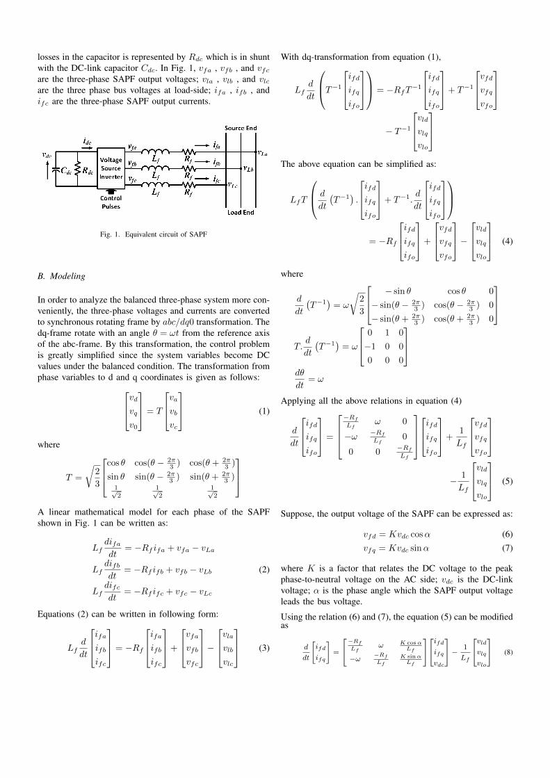
losses in the capacitor is represented by Rdc which is in shuntwith the DC-link capacitor Cdc. In Fig. 1, vfa , vfb , and vfcare the three-phase SAPF output voltages; vla , vlb , and vlcare the three phase bus voltages at load-side; ifa , ifb , andifc are the three-phase SAPF output currents.
Fig. 1. Equivalent circuit of SAPF
B. Modeling
In order to analyze the balanced three-phase system more con-veniently, the three-phase voltages and currents are convertedto synchronous rotating frame by abc/dq0 transformation. Thedq-frame rotate with an angle θ = ωt from the reference axisof the abc-frame. By this transformation, the control problemis greatly simplified since the system variables become DCvalues under the balanced condition. The transformation fromphase variables to d and q coordinates is given as follows:vdvq
v0
= T
vavbvc
(1)
where
T =
√2
3
cos θ cos(θ − 2π3 ) cos(θ + 2π
3 )
sin θ sin(θ − 2π3 ) sin(θ + 2π
3 )1√2
1√2
1√2
A linear mathematical model for each phase of the SAPFshown in Fig. 1 can be written as:
Lfdifadt
= −Rf ifa + vfa − vLa
Lfdifbdt
= −Rf ifb + vfb − vLb (2)
Lfdifcdt
= −Rf ifc + vfc − vLc
Equations (2) can be written in following form:
Lfd
dt
ifaifbifc
= −Rf
ifaifbifc
+
vfavfbvfc
−
vlavlbvlc
(3)
With dq-transformation from equation (1),
Lfd
dt
T−1ifdifqifo
= −RfT−1
ifdifqifo
+ T−1
vfdvfqvfo
− T−1
vldvlqvlo
The above equation can be simplified as:
LfT
d
dt
(T−1
).
ifdifqifo
+ T−1.d
dt
ifdifqifo
= −Rf
ifdifqifo
+
vfdvfqvfo
−
vldvlqvlo
(4)
where
d
dt
(T−1
)= ω
√2
3
− sin θ cos θ 0
− sin(θ − 2π3 ) cos(θ − 2π
3 ) 0
− sin(θ + 2π3 ) cos(θ + 2π
3 ) 0
T.d
dt
(T−1
)= ω
0 1 0
−1 0 0
0 0 0
dθ
dt= ω
Applying all the above relations in equation (4)
d
dt
ifdifqifo
=
−Rf
Lfω 0
−ω −Rf
Lf0
0 0−Rf
Lf
ifdifqifo
+1
Lf
vfdvfqvfo
− 1
Lf
vldvlqvlo
(5)
Suppose, the output voltage of the SAPF can be expressed as:
vfd = Kvdc cosα (6)vfq = Kvdc sinα (7)
where K is a factor that relates the DC voltage to the peakphase-to-neutral voltage on the AC side; vdc is the DC-linkvoltage; α is the phase angle which the SAPF output voltageleads the bus voltage.
Using the relation (6) and (7), the equation (5) can be modifiedas
d
dt
[ifd
ifq
]=
[−Rf
Lfω K cosα
Lf
−ω −Rf
Lf
K sinαLf
][ifd
ifq
vdc
]−
1
Lf
[vld
vlq
vlo
](8)

From the SAPF input-output power balance equation, it canbe written as:
pdc = pf
or, vdciC + vdciR = vfaifa + vfbifb + vfcifc
or, vdcCdcdvdcdt
+v2dcRdc
= vfdifd + vfqifq
or,dvdcdt
=K cosα
Cdcifd +
K sinα
Cdcifq −
vdcRdcCdc
(9)
From the equations (8) and (9), the relation for the dynamicmodel of the SAPF can be derived and is given below:
d
dt
ifdifqvdc
=
−Rf
Lfω K
Lfcosα
−ω −Rf
Lf
KLf
sinαKCdc
cosα KCdc
sinα 1RdcCdc
ifdifqvdc
− 1
Lf
vldvlqvlo
(10)
III. PROPOSED REFERENCE CURRENTEXTRACTOR
The source could be balanced or unbalanced, spectrally pureor distorted. At the same instant, the load could be balancedor unbalanced, linear or nonlinear. Irrespective of the natureof the load, the proposed algorithm is reliable to estimate thereference current which is shown in Fig. 2.
Fig. 2. Proposed reference current extractor
The current drawn by the load is measured through the currentsensor at the point of common coupling. The measured currentis then decomposed into following components:
• Harmonic component: ih,abc• Unbalanced component of fundamental frequency: i1u,abc• Active component of the fundamental frequency: i+1p,abc• Reactive component of the fundamental frequency:i+1q,abc
The role of SAPF is to supply the desirable current compo-nents such that the utility source supply only the active currentcomponent required by the load. The total compensationcurrent for the SAPF is given by
ic,abc = ih,abc + i1u,abc + i+1q,abc (11)
The voltage across DC-link capacitor decays due to switchinglosses in the voltage source inverter. In order to maintain thisvoltage constant, SAPF will draw the necessary amount ofcurrent from the utility source. So, the reference current shouldbe the combination of the compensation current ic,abc and theswitching loss component iloss,abc and is given by
i∗f,abc = ic,abc + iloss,abc (12)
A. Deriving ih,abc
Based on the principle of adaptive noise cancelling theory [5],adaptive detecting algorithm (ADA) extracts harmonic currentfrom the load current which is shown in Fig.3. The system iscomposed of an adaptive filter, a band pass filter (BPF) with50Hz cut-off frequency and 900 phase-shifter. The primaryinput is the load current: iL,abc = i1,abc+ih,abc, where i1,abc isthe fundamental load current, ih,abc is the sum of all harmoniccomponents.In the Fig. 3 vL,abc and v1,abc are the load voltageand its fundamental component, respectively.
Fig. 3. Adaptive detection algorithm
B. Deriving i1u,abc
Instantaneous symmetrical component (ISC) method is a time-domain approach which is mainly deployed in power systemprotection applications [3]. ISC can only be applicable tothe system with single frequency component. With ADA, thesignals (load current and voltage) and its 900-shifted forms arereadily available. The load current at fundamental frequencyis given by
i1,abc = iL,abc − ih,abc (13)
By using this method, load current iLa, iLb, iLc could bemapped onto positive sequence components as,
i+1a(t) =1
3[iLa(t)−
1
2(iLb(t) + iLc(t))−
√3
2(ΓiLb(t)− ΓiLc(t))]
i+1b
(t) =1
3[iLb(t)−
1
2(iLc(t) + iLa(t))−
√3
2(ΓiLc(t)− ΓiLa(t))]
i+1c(t) =1
3[iLc(t)−
1
2(iLa(t) + iLb(t))−
√3
2(ΓiLa(t)− ΓiLb(t))]

where ΓiLa(t), ΓiLb(t), ΓiLc(t) are 900 shifted form of iLa,iLb, iLc respectively. Similarly, load voltage vLa, vLb, vLccould be mapped onto positive sequence components (v+1a, v+1b,v+1c ) using ISC method.
The unbalance component corresponding to the fundamentalfrequency can be derived by subtracting the positive sequencecurrent from the load current due to the fundamental fre-quency.
C. Deriving i+1q,abc
The instantaneous power (pq) theory can be defined forthree phase systems, with or without neutral conductor. Zero-sequence components are absent in three phase three-wiresystems, i.e. i0 = 0. The instantaneous power only existson the dq-axes , as the product v0i0 is zero. Hence,theinstantaneous power p represents total energy flow per unittime, in terms of dq-components. The instantaneous imaginarypower q represents the quantity of the of energy that is beingexchanged between the phases of the system [6].[
p
q
]=
[vd vq
vq −vd
][id
iq
](14)
The above powers can also be expressed in terms of the realand reactive powers corresponding to fundamental (p and q)and harmonic frequencies (p and q). That is,
p = p+ p (15)q = q + q (16)
As the active and reactive current component due to harmonicsis eliminated, they are excluded from the calculation of thereference dq-frame current. Hence, the pq-theory is supposedto supply the reactive power component corresponding tofundamental frequency ( q). So, the reference current in dq-frame is given by:[
i∗di∗q
]=
[vd vq
vq −vd
]−1[0
q
]
=1
v2d + v2q
[vd vq
vq −vd
][0
q
](17)
The pq-theory followed by inverse Clarke transformation (dqto abc) gives the reactive current component (i+1q,abc) corre-sponding to fundamental frequency.
D. Deriving iloss,abc
After a few moment of SAPF operation, DC-link voltage willdecay and become zero because of switching losses in VSI. Inorder to maintain DC-link voltage constant, the compensatingcurrent should flow along with the loss current drawn from theutility source. Initially, the DC-link voltage is sensed througha voltage sensor and then is compared with constant referencevoltage. To nullify the comparator error, a PI regulator is usedto get the corresponding loss current. Further, this current
multiplied to three phase unit vector gives three-phase losscurrent.
Fig. 4. Voltage controller using PI regulator
IV. RESULTS AND DISCUSSION
Distortion and unbalanceness of both load and source isconsidered for simulation study. Initially, a balanced load ofR = 100 Ω and L = 75mH and balanced supply with phase-avoltage, Vsa = 312 sin (100πt) is taken for all the cases. Thereference current would be equal to the fundamental reactivecomponent. The waveforms corresponding to all the cases areshown in Fig. 5 between 0 and 0.4 s. The effectiveness of theproposed algorithm can be explicitly studied by consideringthe following cases.
A. Non-linear Load
The nonlinear load is formed by using three-phase uncon-trolled rectifier module with load of R = 100 Ω and L =250mH . The output current of this load has 33% of harmoniccontent. The waveforms corresponding to above case areshown in Fig. 5 between 0 and 0.1 s. This harmonic currentis generated by the SAPF and is injected in anti-phase withthe load current at the point of common coupling. Aftercompensating the current harmonic, it is observed that the totalharmonic distortion is 1.96% within IEEE-519 limits.
B. Non-linear and Unbalanced Load
Functioning of the SAPF during a non-linear and unbalancedload condition is shown in Figure 5. A three-phase unbalanceload (Ra = 100 Ω, La = 75mH , Rb = 50 Ω, Lb = 90mH ,Rc = 150 Ω, Lc = 65mH) and a non-linear load ofprevious case is taken into consideration. As load currentcontains an unbalance current along with the harmonic one,the compensating current must contain these components. Thewaveforms corresponding to above case are shown in Fig. 5between 0.1 and 0.2 s. After supplying the compensating filtercurrent, the source current becomes balanced, sinusoidal andin phase with the source voltage.
C. Linear Load and Distorted Supply
A sample case of distorted supply with 20% fifth and 13%seventh harmonic is considered for the simulation study. Thewaveforms corresponding to above case are shown in Fig. 5between 0.2 and 0.3 s. These harmonic content (ih,abc) wouldobviously be reflected on the load current which is beingextracted by ADA. The fundamental component can be derivedby subtracting the harmonic one from the original load current(Fig. 5(e)). If the load is having some lagging power factor,it will definitely require reactive power. Due to balanced loadand supply, the harmonic current component will be zero. Asa result, The compensating current is the algebraic sum ofharmonic and fundamental reactive current components (Fig.5(d)).
D. Linear Load, Distorted and Unbalanced Supply
The performance of the proposed technique can be evalu-ated precisely by considering the case of both distorted andunbalanced supply (20% of fifth and 13% harmonics, 20%of fundamental negative sequence voltage). The waveformscorresponding to above case are shown in Fig. 5 between 0.3and 0.4 s. The results represent the robustness of the proposedalgorithm for estimating compensating current even when thesupply is distorted and unbalanced. It is observed from [8]that three cycles is the minimum time required to estimate thereference current. But the proposed algorithm is fast enoughto give the response in less than one cycle which is shown infig. 5.
V. CONCLUSION
In this paper, a novel reference current extraction methodusing adaptive detection algorithm is proposed which is ableto extract the harmonic content from the load current. Alongwith instantaneous symmetrical component method and pqtheory, this algorithm is able to estimate the reference currenteven with distorted and unbalanced supply, as well as thenon-linear and unbalanced load. This closed loop system isindependent of parameter variation and behave as a notch filter.The proposed method is studied analytically and verified byMATLAB/Simulink simulation environment. Finally, simula-tion result is given to conform the feasibility of the hardwarerealization.
REFERENCES
[1] C.K. Duffey, R.P. Stratford, “Update of harmonic standard IEEE-519-IEEE recommended practices and requirements for harmonic control inelectric power systems,” Industry Applications Society Annual Meet-ing,vol.2, pp.1618-1624, Oct. 1989.
[2] W. L. A. Neves, H. W. Dommel, and W. Xu, “Practical distribution trans-former models for harmonic studies”, IEEE Trans. on Power Delivery,vol. 10, pp. 906 -912, Apr. 1995.
[3] W. V. Lyon, Transient analysis of alternating-current machinery, NewYork, John Wiley, 1954.
[4] Bhim Singh, Kamal Al-Haddad,“A review of active filters for powerquality improvement”, IEEE Transactions on Industrial Electronics, vol.46, NO. 5, Oct. 1999.
[5] B. Widrow, J.R.Glover, Jr., J.M. McCool, “Adaptive noise cancelling:Principles and applications,” Proceedings of the IEEE , vol.63, no.12,pp.1692,1716, Dec. 1975.
[6] H. Akagi, Y. Kanazawa and A. Nabae,“Instantaneous reactive powercompensators comprising switching devices without energy storage com-ponents”, IEEE Trans. on Industry Applications, vol. 20, no. 3, May/June1984.
[7] G. C. Paap, “Symmetrical components in the time domain and theirapplication to power network calculations,” IEEE Trans. on Power System,vol. 15, pages 522-528, 2000.
[8] M. K. Ghartemini, M. R. Iravani and F. Katirei,“Extraction of signalsfor harmonics, reactive current and network-unbalance compensation,”lEE Proc. on Generation, Transmision and Distribution, vol. 152, pages137- 143,2005.
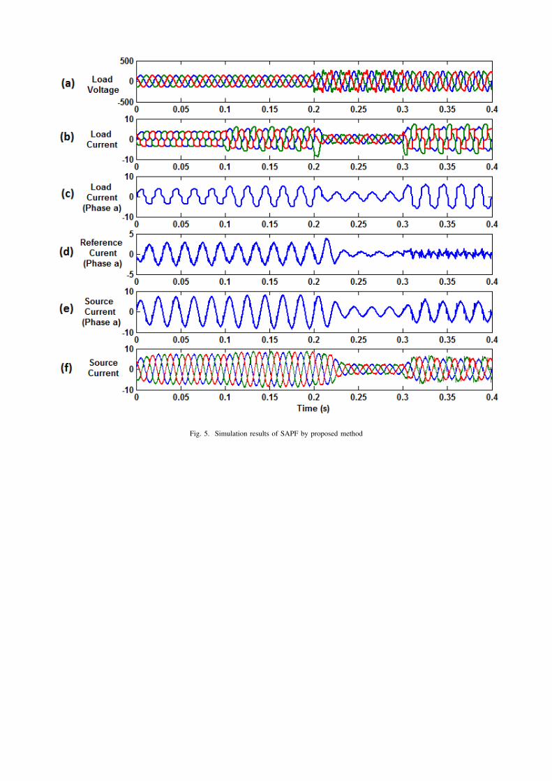
Fig. 5. Simulation results of SAPF by proposed method