Embed Size (px)
Citation preview

A DYNAMIC MICROPHONE FOR THE
SOUND-LEVEL METER
IN TH IS ISSUE Page
E :fERGE CY Po,YJ..:R EQUIPMENT FOR FREQUENCY STAND-AUDS . . . . . • . . . . . . . 5
•IN THE DESIGN of a general-purpose sound-level meter, one of the important
problems is the choice of a mic1 ophone.
Among the many desira.Lle microphone
characteri tic , there are several that are
essential if the instrument is to do a credit
able job of measurement. In addition to having a non-directional, wide, flat, fre-
quency response and high sensitivity, the
microphone should give a linear respon e o er a wide range of sound
pressure levels, and its output should be stable over long periods of
time -not adversely affected by variations of temperature or humidity.
The National Production Authority Regulation 4 provides a uniform
procedure by which any business enterprise, government agency, or
public or private institution may use a priority rating to obtain "minor
capital additions" as well as specified quantities of maintenance, re
pair and operating supplies (MRO).
Within the restrictions of the Regulation, a rating of D0-97 may be
used on orders for these materials and services. Specific authorization
for each order is not required. Test equipment and laboratory apparatus
of the kind manufactured by General Radio are usually accounted as
capital additions. The Regulation permits your use of the priority rating
when the cost of one complete capital addition does not exceed $750. In general, the amount that may be obtained under the rating is
limited, with minor adjustments, to a total dollar value per quarter equal
to one-fourth of the amount that was spent in 1950 for MRO.
Because so many priority-rated orders are being received, deliveries
against unrated orders are becoming increasingly uncertain. We recom
mend that, if no other rating is available, 00-97 be used whenever it is
applicable.
NPA Regulation 4 should be consulted for details. Copies are avail
able from your nearest Department of Commerce field office.
"\
www.americanradiohistory.com

GE NER AL R ADIO EXPERI ME NTER 2
2500 /\ I \ �2000 :::>.
� _1500 � "--..... -- _/ ' i'..... i3 1000 ft ........
"' <( Q 500
0 0 20 30 40 50 60 70 80 90 100 110 TEMPERATURE "F
Figure 1. Capacitance variation as a function of tern-. perature for a typical Rochelle salt crystal microphone.
THE ROCHELLE SALT CRYS TAL MICROPHONE
The Rochelle sal cry tal, diaphragmtype microphone chosen for use on the
General Radio TYPE 759-B ound-Level
Meter i a low-co t device, which ful
fills all of these requirements sati fa -
torily o long as the microphone i con
nected directly to the input terminals
of the ound-level meter, and o long as moderat variations of temperature and humidity are encountered ..
However, when it become necessary
to rnal e mea "Luemen ts with the microphone separated from the sound-level meter by a long cable or when high temperature and humidity are ncoun tered , the Rochelle salt crystal microphone
becomes a less satisfactory pickup. While
the output voltage of the microphone change by about .02 db per degree F., its capaci ance varies considerably a
the temperature change so that lo
added by a long cable is very markedly
a function of temperature. Figure 1 hows the variation in ca
pacitance with temperature for a typical
Rochelle al cry tal microphon . At the top of Figure 2 the dashed curve how the change in output of the microphone
\ ith temp ratur and th olid urv
how th change in m t r reading of
the TYPE 759-B Sound-Level Meter due
to temperature chang at the micro-
phone with he microphone mounted on the ound-1 vel meter. 'I'h t o low r curves show the large change in met r reading that occur when 25-f oot and 100-foot cabl r p ctively are u ed between the microphone and th oun dlevel meter. The maximum safe tem
perature a which th Rochelle salt un it can be u ed i abou 11 -° F., ince
it is permanently damaged at tempera
ture above 135° F. Although the unit i
sealed, extensive u e at a relative humidity below 30 or abov 5 hould be
avoided.
THE DYNAMIC M.ICROPHONE The rror ari ing from the eff ec
can be a voided by he u e of a dynamic,
or moving coil, microphone for those
appli ations where a long cable mu t b
used be ween microphone and oundlevel meter, or '\ here extreme of tem
perature and humidity are encountered . A uitable dynamic microphon for
use wi h the TYPE 759-B Sound-Level
Meter i now availabl , in ombination with a transformer, a cable and tripod.
Figure 2. Variation in response as a function of temperature for the crystal microphone alone and with various lengths of cable between microphone and
+ I
0 I
-2 -3 -4
,g -5 I w
� -6
(f) -7 w a:: w -8 > � -9 __J w a:: -10
-11 -12 -13 -14
----
'---
'-..._ .._
sound-level meter.
----�-
� �
7' \. / '\
__,..,. "'
f\ 7 \
, \ I \
_/)' \ \
--
r-
�
,_MIC I I ROPHONE ONLY
MICR OP HONE NO LEVEL METER ... sou
"WITH 25 FOOT E(675JJµf) CABL
\ \ WITH
CABLE IOOFOOT (2700JJµf) 20 30 40 50 60 70 80 90 100 110
TEMPERATURE °F
www.americanradiohistory.com

3
Thi ·ombina ion , the TYPE 759-P25
Dynamic Microphon and Ac e one , i hown in Figure 3.
The dynamic microphon th We t
ern El ctric type 633-A, now manu
fa tur d by Altec Lan ing orporation,
i well e tabli h d a a d p ndable and
rugg d in trument. It output level is
about -90 db re J olt per microbar
co1npared to a level of -60 db for th
crystal microphone, o tha a tran -
former with a turn ratio of 30 :1 i re
quired to raise the output to th de ired
level. The TYPE 759-322 Transformer
do hi with no effect on he frequency
r spon e over th working range of th
microphone. In addition the transform r
i well hielded, so that pickup from
tray m gnetic field is well below any
u h pickup by the microphone it elf.
The cable furni h d is 25 feet of shielded
double conductor with vinylite heath.
A 100-foot cable i al o available.
Figure 4 show a typical field re pon
for the TYPE 759-P25 a mbly u ed
with a TYPE 759-B ound-Level Meter
on the C (flat) weigh ing n t' ork. For
ound arriving at random, the re pon e
fall within the toleranc allowed in th
AS tandard on ound-level meter
(Z24.3 l 944). It should be noted, how-
er, that the r ponse below 1000 cycle
i not o fla a hat of the crystal dia
phragm- ype microphone, a can b en
b. comp ring Figure 4 with Figure 5.
The response at 400 cycles , for the d -
namic mi rophon , i near the center of
a broad ma imum, o that if the gain of
the sound-level meter is set to gi or-
APRI L, 1 951
Figure 3. View of the Type 759-P25 Dynamic Microphone and Accessories connected to a Type 7 59-8
Sound-Level Meter.
r ·t r ading ba ed on he 400-c cle
n itivit of the microphone, sound
level reading of averag or broad-band
noise will b low. At fr quencie below
30 cycle the output of the dynamic
mi rophon fall off harply while the
output of the crystal uni i g od to 20
cycle and low r.
At frequ ncie abov about 6000 cy
cle th op ration of he dynamic micro
ph n i uperior o the operation of th
er tal microphone. For ounds arriving
a random, h difference in operation i
not great. A hown in Figure 4 and 5,
Figure 4. Typical response curves for the Type 759-B Sound-Level Meter with Type 759-P25 Dynamic Microphone and Accessories. -50 0:: er al
0 0:: (.) � � -60
':i � .. � -70 i3 20
'--ir
50
-
100
·�-0 _ ..... ... ----:- -- ___., �- .... --
200 500 1000 2000 FREOUENY IN CYCLES PER SECOND
- -� , ... .. -,... ,_ _...
�--i-- - .... ':" '
5000
�
-,
'""�' OUND ARRIVING AT O"
�--js OUNO ARRIVING
AT RANDOM
',I* r OUNO AR RIVING AT 90• 10000
www.americanradiohistory.com
{3 +1 0 i.L (f) 5 B; w 0 0:: w > � :5 -10
...--
GE NER A L R ADIO EXPERI ME NTER
� � ,,,.
- \;
4
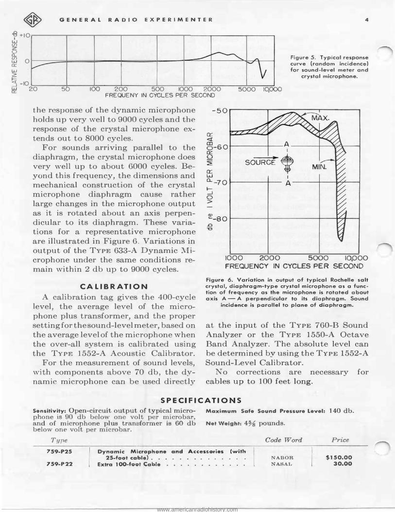
Figure 5. Typical response curve (random incidence) for sound-level meter and
crystal microphone.
� 20 50 100 200 500 1000 2000 FREQUENY IN CYCLES PER SECOND
5000 10.000
the response of the dynamic microphone holds up very well to 9000 cycles and the response of the crystal microphone extends out to 8000 cycles.
For sounds arriving parallel to the diaphragm, the crystal microphone does very well up to about 6000 cycles. Beyond this frequency, the dimensions and mechanical construction of the crystal microphone diaphragm cause rather large changes in the microphone output as it is rotated about an axis perpendicular to its diaphragm. These variations for a representative microphone are illustrated in Figure 6. Variations in output of the TYPE 633-A Dynamic Microphone under the same conditions remain within 2 db up to 9000 cycles.
CALIBRATION A calibration tag gives the 400-cycle
level, the average level of the microphone plus transformer, and the proper setting for the sound-level meter, based on the average level of the microphone when the over-all system is calibrated using the TYPE 1552-A Acoustic Calibrator.
For the measurement of sound levels, with components above 70 db, the dynamic microphone can be used directly
a::: <( �-60 -----+---A ___ .,.___..,....... __ a:: I � SOURCE'
W I
o.. _7 O -----+--- A---+-----..----1 ..._ _J 0 >
(1) �-a o 1-------+---------......., ...... ---1
.0 �
1000 2000 5000 10,000 FREQUENCY IN CYCLES PER SECOND
Figure 6. Variation in output of typical Rochelle salt crystal, diaphragm-type crystal microphone as a func· tion of frequency as the microphone is rotated about axis A-A perpendicular to its diaphragm. Sound
incidence is parallel to plane of diaphragm.
at the input of the TYPE 760-B Sound Analyzer or the TYPE 1550-A Octave Band Analyzer. The absolute level can be determined by using the TYPE 1552-A Sound-Level Calibrator.
No corrections are necessary for cables up to 100 feet long.
SPECIFICATIO S Sensitivity: Open-circuit output of typical micro- Maximum Safe Sound Pressure Level: 140 db. phone is 90 db below one volt per microbar, and of microphone plus tran former is 60 db Net Weight: 4% pounds. below one volt per microbar.
Type Code Word Price 7 59-P2 5
I
Dynamic Microphone and Accessories (with 2 5 -foot cable} . NABOR $1 50.00
759-P22 Extra 100-foot Cable NASAL 3 0. 00
www.americanradiohistory.com
5 A PRI L, 1951
EMERGENCY POWER EQUIPMENT FOR FREQUENCY
Official time for all Canada is provided by the Dominion Observatory at Ottawa, whose time signals, sent by direct wire and radio, are available to the Canadian public from Halifax to Victoria, and northward to the limits of
radio reception. The crystal clock has superseded the
pendulum type as the primary timekeeper at the Dominion Observatory, although here, as in most observatories, the pendulum, because of its simplicity and reliability, is still an important element in the time-determining system.
The crystal clocks at the Dominion Observatory are General Radio Primary
STANDARDS Frequency Standards. Both are equipped with Syncronometers indicating mean time. Two additional Syncronometers, controlled by one of the crystal clocks, are used, one to compare the mean-time clocks with radio time signals from other observatories, particularly Washington and Greenwich, and the other to initiate the time signals transmitted from the Observatory. Time signals in a standard identification sequence are transmitted by a pendulum-controlled time-signal machine, upon which a signal from a crystal clock circuit is superimposed as a gate for the beginning of each second's
impulse.
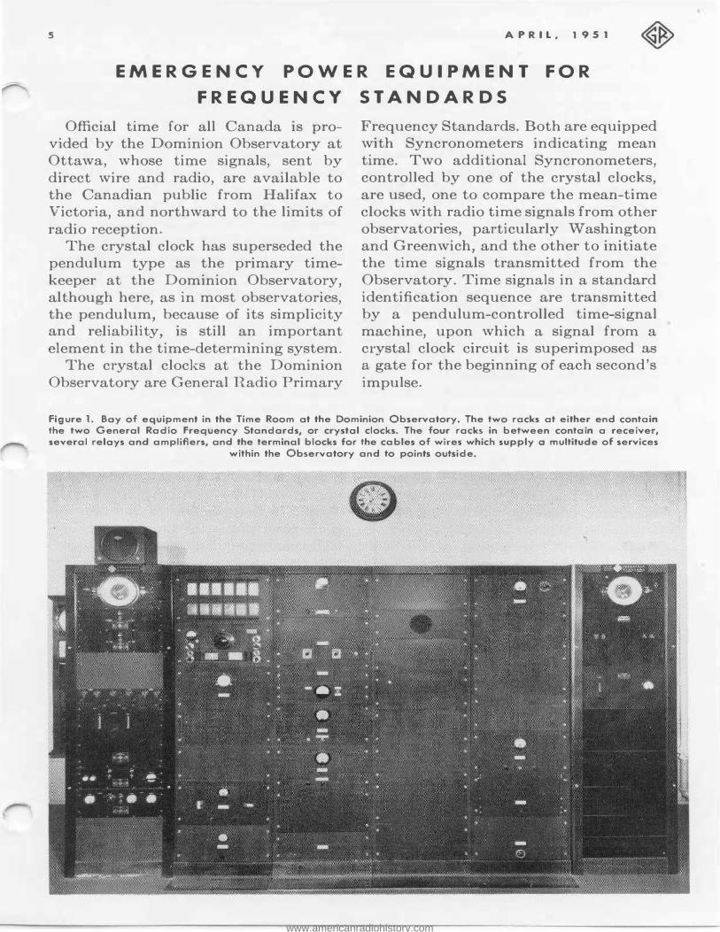
Figure 1. Boy of equipment in the Time Room ot the Dominion Observatory. The two racks at either end contain the two General Radio Frequency Standards, or crystol clocks. The four racks in between contain a receiver, several reloys and amplifiers, and the terminal blocks for the cables of wires which supply o multitude of services
within the Observatory and to points outside.
www.americanradiohistory.com

G EN ER AL R A DIO EXP ERI M ENT ER 6
POWE R SUPPLY Pendulum clocks po e no enou
power upply problem , becau e they
operate from batteries, which are con
tinuou ly haro-ed by rec ifier equipm nt
operating from th a-c pow r line. In th
event of line failure, emergency charging
equipment automati ally take over in a matt r of a few econd .
The cry tal clock, however, when
operated directly from h a-c line, top
operating wh n a power interruption of
even short duration occur . Because the
cry tal lock offer so much gr a r pr -
ci ion than the pendulum type, con ider
able effort has been expended by the
Dominion Ob rva ory in devi ing a ati factory method of bridging the
po' er-supply interruption .
ne of th original m thod ad p d to provide continui y of power was complete battery supply for both high volt
ag and low voltag . Th battery banl
meanwhile i kept up to tr ngth by
m ans of a trickle charge. Immediate!
th power line fail , th b tterie carry
ov r, and, \; h n th pow r r turn the
rickl charge o he ba terie is resumed.
All the e sential equipm nt f r he main
tenanc of the time- ignal machine and
it primary pendulum at he Dominion
0 rvatory i maintained by thi float
ing batt ry method. Ther are, ho\; ever certain objection
to th u of the f-loa ing batt ry. Th
space required by batterie for full-voltage supply becomes exce sive, particu
larly with the mod rn tubes "\ hi h u
high r plate voltage . rrhe fume from such a large bank may not be inconsider
abl at time and mu b drawn off.
When the charg i withdrawn, the
voltage changes fairly abruptly by about
t n p r cent, providing all the cell of
the bank are good. If any bad cells exi t,
which i quite po ibl , the hange in
voltage from charg to n charg can b till gr a r. I i exp cting a good d al
f present-day equipment to provid a mooth continui y f outpu with fiuctua
ions in power supply v n a great as
five per cen . Furth rmore, when th
quipment i de ign d for normal 60-ycl op ration, p ial lead mu t be
in talled to adapt it for batter op ra
tion. Ao·ain h di advantag , of our , i he great advantage hat the
power available to the quipment n er
fall below the ba tery 1 vel, and u ually long continuity of ervice may b ex
pected. Another type of m rg ncy for bridg
ing period of pow r failure involve the
use of batteries and a 0-cycle, 110- olt
dynamotor or motor g nera or. Durino·
normal operation, the ba tery driv he dynamotor, which in turn suppli h
r quired pow r to the lectronic equipm nt. Th a-c lin op rates through a r tifier o provide th batterie with
barge ufficient to maintain th dyna
mo or, and al o to ompen ate f r th
normal batt ry d cay. A he moment
of an interruption in th ljne, th bat
terie con inu ind pend ntly and main
tain the dynamotor. Resumption of h line r turn the harg circuit to i
normal rate. dynamotor, which oper
a es from a 32-volt batter bank, will
involv a c mpromi b ' ee ffi i n y and economy of pac , and equipment designed for normal 110-volt, 0- ycl
operation v ill r quir no chang . b
j ctionable f atur in lude the fa tha
rotating machin ry r quire maint -nan and in olv om no1 and vibra-
ion. With an in erruption in the lin and the charo-e r moved from the bat
tery, the volt g appli d to th dyna
mo or drop qui kly b one-tenth or
more, and he input voltage to th
equipment al o drop .
www.americanradiohistory.com

7
32 VOLT BATTERY
HOV 60.....,. LINE
·
----�
MAGNETIC 8LOW·OUT RELAY
OPOT RELAY
llOV 60-TO EQUIPMENT
Figure 2. Schematic of the 32-volt d-c, 110-volt a-c motor generator set used in connection with each of the crystal clocks to provide emergency power with little delay. While a unit of this nature is capable of operating for a considerable time, limited only by the condition of the batteries, its main purpose is to provide a very quick source of 110 volts ac to tide over the short interval required for the gas-driven motor
generator to build up.
A varia ion of the above method, and
one which ha b en placed in service at
th Dominion Ob ervatory, in lude th
u of a 32-volt dynamotor and a bank
of 1 ad cell to provide the required 32
volts. In this y tem he 60-cy ·l , a-c
lin i u ed t provide power for the
electronic equipment, and also a trickle
charge to the batt ry. A line witch i so
arranged hat when the power fail the
line is cut off, the battery i cut in to the
dynamotor, and the a-c ou put of the
dynamotor i cut in to the equipment.
The mea ured delay from the ime
that the a-c line i interrupt d till th
tim that the dynamotor builds up to
APRIL , 1951
full frequen y and voltag proves to be
about 0.6 econd. The normal pow r
supply has to be provided with addi
tional high voltage storag to bridge a time gap of this size. In the
·ca e of the
frequency standard a the Dominion
Observatory, seven electrolytic conden -
ers of ighty microfarads provide ade
quate storage.
The initial charging of uch a large
conden er i beyond the normal abili y
of th ordinary r ctifier tube without
om protection. With a re i tance of
ay three th usand ohm in series when
the condens r is initially charged, the
job can be handled quite well by the
familiar type 80 ube. Once the charge
has been made, the r i or may be
hor ed out becau e, in short interval
of a cond, the conden er will suffer
only a partial di charge. Te t in service
indicate that it does serve effectiv ly to
maintain th high oltage during the
period of witch over. Jo uch pr cau
tion is nece ary for th cathod pow r, sine the ordinary type of heater tube
suffers little change with a power cu off
of one second. On re toration f the
dom tic a-c upply, the line witch
again clo e , th dynamotor cut off to
await he next interruption, and th
batteries re urn to their ri ·kl charge.
Figure 3. A recording on a drum which rotates at one revolution per second shows that the build-up time of the motor generator emergency power supply is less than half a second. The instant when the domestic power supply was cut off by pulling the switch is marked by A. The interval from A to B was required for the motor generator
supply to build up to full frequency and voltage.
•
www.americanradiohistory.com
GENER A L R A DIO EXPERI MENTER 8
The build-up time of 0.6 second re
f erred to above was measured on a drum
chronograph which is made to rotate
synchronously at one revolution per
second. The syphon pen can be made to
record the 60-cycle wave from the line
at the point where it is fed into the fre
quency standard. When a line interrup
tion is simulated by opening the line
switch, there is an immediate interrup
tion in the a-c pattern being recorded.
As the dynamotor comes up to speed,
the emergency a-c supply operates the
pen, showing clearly the moment when
full frequency and voltage are attained,
and the elapsed time proves to be about
0.6 second. There are certain inherent faults in
the use of a dynamotor and stand-by
battery as an emergency source of power.
The ordinary switch will maintain itself
over a wide range of voltage, which
means that the domestic a-c supply
might drop to a low voltage due to a
partial short without the switch operat
ing. A drop to say 80 volts, which might
be quite adequate to maintain a switch
in the up position, would be quite inade
quate to maintain a frequency standard
at normal operation. However, such a condition is rather infrequent, and the
experience at the Observatory to date
has not indicated the need to adopt one
of the sensitive type of switches which
would operate within very narrow voJt
age limits.
The emergency power supply de
scribed above is designed for rapid
pickup. It will, as a matter of fact, give
continuous service for several minutes,
or even hours, depending on the state of
the batteries. Normally the heavy duty
stand-by power plant, which is gas
driven, takes over within a quarter of a
minute, so that the use of the emergency
supply is for short intervals only.
In the several years that this emer
gency system has been in operation,
there has been no failure caused by
power interruptions in the frequency
standard which is now being used as the
primary timekeeper at the Dominion
Observatory.
The information on which this article is based was supplied by J. P. Henderson and M. M. Thomson of the Dominion Observatory, Ottawa, Ontario. Additional information on the time service supplied by the Observatory will be found in an article by Mr. Thomson entitled "Canada's Time Service," published in the Journal of the Royal Astronomical Society of Canada, XLII, 3, pp. 105-120, 1948.
TllE General Radio EXPERIMENTER is mailed without charge each
mont,h to engineers, scientists, technicians<> and others interested
in communication-frequency measurement and control problems.
When sending requests for subscriptions and address-change notices,
please supply the following information: name, company address, type
of business company is engaged in, and title or position of individual.
GENERAL RADIO COMPANY 275 MASSACHUSETTS AVENUE
CAMBR IDGE 39 MASSACHUSETTS TELEP H 0 NE : TR owbridge 6 - 4 4 0 0
BRANCH E NG INE E R ING OFFICES NEW YORK 6, NEW YORK
90 WEST STREET
TEL.-WOrth 2-5837
LOS ANGELES 38, CALIFORNIA
1000 NORTH SEWARD STREET
TEL-HOiiywood 9·6201
CHICAGO 5, llllNOIS
920 SOUTH MICHIGAN AVENUE
TEL. WAbash 2·3820
www.americanradiohistory.com