Embed Size (px)
Citation preview

Open FOAM
Dynamic Mesh Handlingin OpenFOAM
Hrvoje Jasak
Wikki Ltd, United Kingdom and
FSB, University of Zagreb, Croatia
7-9th June 2007
Dynamic Mesh Handlingin OpenFOAM – p.1/11

Open FOAM
Geometry Handling
f
P
Vy
z
x
N
d
sf
f
r
X
Z
Y
Handling Complex Geometry in OpenFOAM
• Complex geometry is a rule, not exception
• Polyhedral cell support◦ A cell is a polyhedron bounded by
polygons
◦ Consistent handling of all cell types
◦ More freedom in mesh generation
• Interfaces to all major mesh generators
Automatic Mesh Generation
• Two techniques under active development,based on STL surface geometry description
• Polyhedral dual mesh from Delaunay triangula-tion and cut cell technique
Dynamic Mesh Handling
• Supporting cases of deforming geometry usingmesh motion solvers
• For extreme mesh deformation, mesh topologyis modified during the simulation
Dynamic Mesh Handlingin OpenFOAM – p.2/11
Open FOAM
Automatic Mesh Motion
Handling Shape Change: Problem Specification
• Initial valid mesh is available
• Time-varying boundary motion
◦ Prescribed in advance: e.g. IC engines
◦ Part of the solution: surface tracking
• Need to determine internal point motion based on prescribed boundary motion
• Mesh in motion must remain valid: face and cell flip must be prevented by thesolution algorithm and control of discretisation error
Solution Technique
• Point position provided by solving an equation where motion of the boundary actsas the boundary condition for the motion equation
• Choice of motion equation: Laplace or pseudo-solid equation
• Details of mesh grading controlled by variable diffusivity, based on distance to themoving boundary, cell distortion or similar criteria
• Current implementation allows multiple solver techniques. Experience showscell-based methods fail in interpolation; spring analogy technique is unreliable
Dynamic Mesh Handlingin OpenFOAM – p.3/11
Open FOAM
Automatic Mesh Motion
Solving Mesh Motion Equation
• Vertex-based (FEM) mini-element discretisation taken out by OpenCFD Ltd.without appropriate replacement
◦ Well tested, parallelised and in active use: essential for IC engines simulation
◦ Replaced by inferior cell-based technique with interpolation issues
◦ It will remain present in the public version of OpenFOAM
• Cell-based motion solver◦ Faster than the FEM technique: segregated cell-based FVM solver with
interpolation
◦ For simple meshes and smooth boundary motion, it is useful; it will fail formore complex motion cases
• Variable diffusivity operates in the same manner in both techniques
Dynamic Mesh Handlingin OpenFOAM – p.4/11

Open FOAM
Automatic Mesh Motion
Effect of Variable Diffusivity: Oscillating Airfoil Simulation
• Initial mesh; constant diffusivity
• Distance-based diffusivity 1/l2; deformation energy; distortion energy
X
Y
Z
Dynamic Mesh Handlingin OpenFOAM – p.5/11
Open FOAM
Topological Mesh Changes
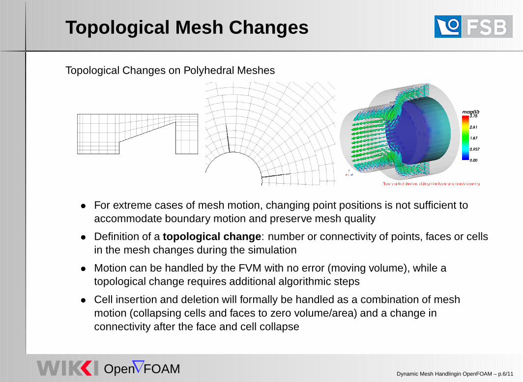
Topological Changes on Polyhedral Meshes
• For extreme cases of mesh motion, changing point positions is not sufficient toaccommodate boundary motion and preserve mesh quality
• Definition of a topological change : number or connectivity of points, faces or cellsin the mesh changes during the simulation
• Motion can be handled by the FVM with no error (moving volume), while atopological change requires additional algorithmic steps
• Cell insertion and deletion will formally be handled as a combination of meshmotion (collapsing cells and faces to zero volume/area) and a change inconnectivity after the face and cell collapse
Dynamic Mesh Handlingin OpenFOAM – p.6/11

Open FOAM
Topological Mesh Changes
Implementation of Topological Changes in OpenFOAM
• Primitive mesh operations◦ Add/modify/remove a point, a face or a cell
◦ This is sufficient to describe all cases, even to to build a mesh from scratch◦ . . . but using it directly is very inconvenient
• Topology modifiers◦ Typical dynamic mesh operations can be described in terms of primitive
operations. Adding a user-friendly definition and triggering logic creates a“topology modifier” class for typical operations
◦ Implemented topology modifiers∗ Attach-detach boundary∗ Cell layer additional-removal interface∗ Sliding interface∗ Error-driven mesh refinement
• Dynamic meshes◦ Combining topology modifiers and user-friendly mesh definition, create
dynamic mesh types for typical situations
◦ Examples: mixer mesh, IC engine mesh (valves + piston) etc.
• User define own modifiers and dynamic meshes. Example: crack propagation
Dynamic Mesh Handlingin OpenFOAM – p.7/11

Open FOAM
Topology Modifiers
Example: Layer Addition-Removal
• Layer addition-removal mesh modifier removes cell layers when the mesh iscompressed and adds cells when the mesh is expanding
• Definition consists of:◦ Face zone, defining oriented active surface for cell addition and removal
◦ Minimum and maximum mesh thickness in front of the surface
• Triggering condition derived from mesh motion (handled separately)
• Example definition: constant/polyMesh/meshModifiers
right{
type layerAdditionRemoval;faceZoneName rightExtrusionFaces;minLayerThickness 0.0002;maxLayerThickness 0.0005;oldLayerThickness 0.0;active on;
}
Dynamic Mesh Handlingin OpenFOAM – p.8/11
Open FOAM
Topology Modifiers
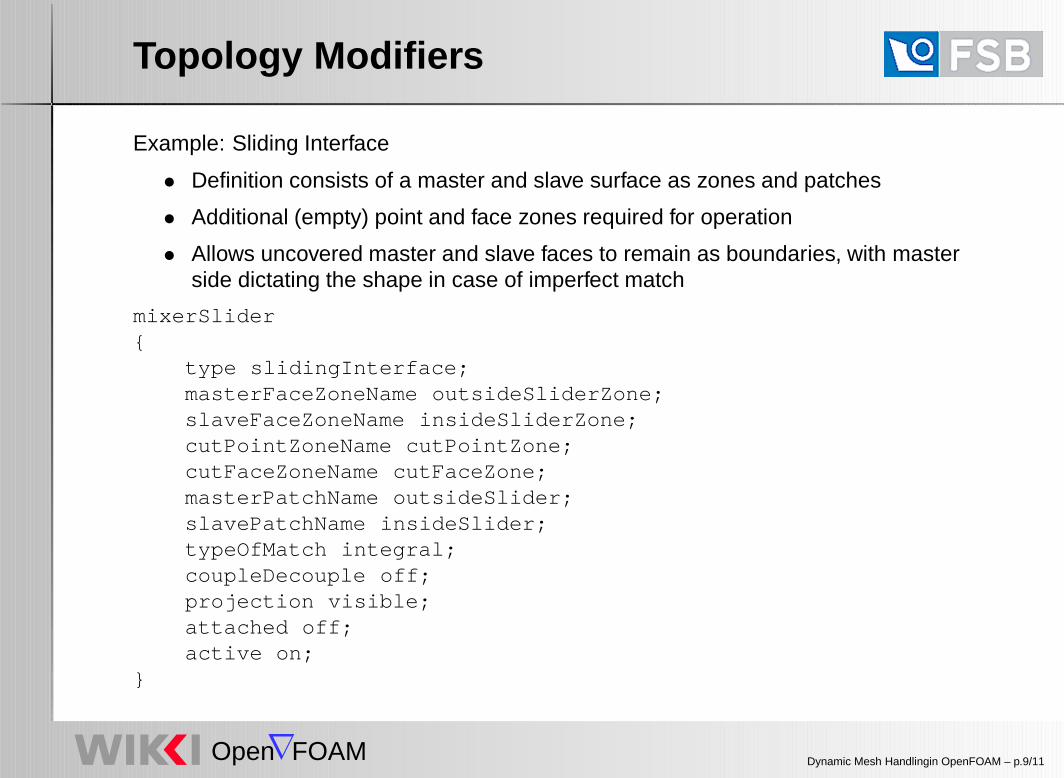
Example: Sliding Interface
• Definition consists of a master and slave surface as zones and patches
• Additional (empty) point and face zones required for operation
• Allows uncovered master and slave faces to remain as boundaries, with masterside dictating the shape in case of imperfect match
mixerSlider{
type slidingInterface;masterFaceZoneName outsideSliderZone;slaveFaceZoneName insideSliderZone;cutPointZoneName cutPointZone;cutFaceZoneName cutFaceZone;masterPatchName outsideSlider;slavePatchName insideSlider;typeOfMatch integral;coupleDecouple off;projection visible;attached off;active on;
}
Dynamic Mesh Handlingin OpenFOAM – p.9/11

Open FOAM
Dynamic Meshes
Example: Multi-Valve Engine Mesh
• Even for simple cases, it is easier to speak about problem classes (mixer vessels,engines, moving bodies) rather than working out individual topology modifiers
• For complex topological changes, multiple interacting topology modifiers are usedand need to be synchronised and used in unison with mesh motion
• Example: engine valve
◦ Definition identifies valve stem, top and bottom surface
◦ Topology modifiers: layer addition-removal on top and bottom surface; slidinginterface along valve curtain
◦ Valve motion defined in terms of valve lift curves and crank angle degree
• Engine mesh components
◦ Piston class, with motion defined in terms of crank angle degree and celllayering thickness
◦ List of valves, each with own lift curve◦ Identification of intake and exhaust ducts (possibly allowing removal when
valves are closed)
• The user builds the mesh and associates various surfaces to engine components:easy setup after mesh generation
Dynamic Mesh Handlingin OpenFOAM – p.10/11

Open FOAM
Dynamic Meshes
Example: In-Cylinder Flow with Moving Piston and Valves
• Exhaust and intake stroke in a 2- and 4-stroke engine
• Moving piston and operating valves using topological changes
• Examples by Tommaso Lucchini, Politecnico di Milano
Dynamic Mesh Handlingin OpenFOAM – p.11/11

![Algoritmos para gera˘c~ao da triangula˘c~ao de Delaunay ... · A triangula˘c~ao de Delaunay foi proposta por Delaunay [3] e possui a propriedade de maximiza˘c~ao do angulo m nimo](https://img.dokumen.tips/doc/110x75/5c60c20109d3f21b6a8c017b/algoritmos-para-geracao-da-triangulacao-de-delaunay-a-triangulacao.jpg)