Embed Size (px)
Citation preview

Nordstrom Valves
Dynamic Balance® Plug Valve and Double DB® Plug ValveInstallation, Operation and MaintenanceFCD NVENIM2005-01 (Replaces V170-PED)

Contents1 Valve Selection 4
1.1 Introduction 41.2 Pressure-Temperature Rating 41.3 Bending Strength 41.4 Fire Safety 41.5 Pressure Surge 51.6 Throttling Service 51.7 Temperature Changes 51.8 Other Pressurization 51.9 Trapped Pressure 51.10 Material Compatibility 51.11 Operating Effort 6
2 Shipping And Storage 62.1 Introduction 62.2 Handling 62.3 Storage 6
3 Installation 63.1 Introduction 63.2 Inspection 63.3 Threaded Valve to Pipe Assembly 73.4 Flanged Joint Assembly 73.5 Weld Joint Assembly 83.6 Proprietary End Connection Assembly 83.7 Testing and Adjustment 9
4 Operation And Maintenance 94.1 Introduction 94.2 Operation, Manual Valves 94.3 Operation, Power-Actuated Valves 94.4 Fluid Dynamics of Shutoff Valve Operation 104.5 Noise 104.6 Maintenance 11
5 Dynamic Balance Plug Valve Maintenance 115.1 Notice 115.2 Customer Service 115.3 Field Service 115.4 When You Call or Write Us 125.5 Product Identification 125.6 Economics of Valve Repair 125.7 Video Training 135.8 Introduction 135.9 Earlier Designs 135.10 Basic Construction Principles 135.11 Sealant System 145.12 Design Features 145.13 Valve Front Identification 155.14 Gearing 155.15 Sealants 155.16 VXX Valve Purge 155.17 Sealant Injection Equipment 155.18 Valve Maintenance 165.19 Basic Sealant Injection 16
6 Valve Maintenance: Troubleshooting 17

7 Technical Data 237.1 Part Identification Reference 237.2 Exploded Views 247.3 Detail Sketches 25
8 Procedure for Tightening Cap Screws and Nuts 299 Tables 30
FiguresFigure 1 – Illustration of typical nameplate 12Figure 2 – Location of Relief Fitting 13Figure 3 – Gauge 16Figure 4 – Wrench-Operated Valve 24Figure 5 – Stem End Detail: Wrench-Operated Valve 25Figure 6 – Stem End Detail: Gear-Operated with Bolt-on Gear Flange 25Figure 7 – Stem End Detail: Gear-Operated with Cast On Gear Flange 26Figure 8 – Cover End Detail: Size 6 and Larger with Pressure Seal Arrangement 27Figure 9 – Cover End Detail: Size 6 and Larger with Spring Disk Arrangement 27Figure 10 – Cover End Detail: Size 6 and Larger with Ball Seat Arrangement 28Figure 11 – Cover End Detail: Size 4 and Smaller 28Figure 12 – Bolt-tightening patterns 29
TablesTable 1– Size 4 and Smaller Valve Gland Bolting 30Table 2 – Size 4 and Smaller Valve Cover Bolting 30Table 3 – Size 6 and Larger Valve Pressure Retaining Bolting (all parts) 30Table 4 – Plug Adjusting Screw Torque Values 31Table 5 – Sealant Capacities 32

Flow Control
Nordstrom Valves
4 Dynamic Balance® Plug Valve and Double DB® Double Isolation Plug Valve FCD NVENIM2005-01
1 Valve Selection1.1 IntroductionIt is beyond the scope of this manual to make recommendations for specific applications. This manual is intended to call attention to important considerations in the selection of valves. Keep in mind that misapplication of a valve type could result in operating problems that adversely affect system safety and efficiency. The manual addresses the important subjects of Shipping and Storage, Installation, and Operation and Maintenance. Observance of the recommendations and practices offered provides increased assurance of satisfactory valve performance.
The valve industry offers a wide variety of valve types and materials for use in industrial piping applications. There are usually several possible choices for any given requirement and any one valve may offer significant advantages and/or limitations when compared with another valve. It is good practice to consult the manufacturer regarding specific requirements. When purchasing valves, low cost is certainly a major consideration, but also important is ensuring that the valves purchased are satisfactory for the intended service. The lowest total user (life cycle) cost criteria should be used only in choosing between alternatives that are known to satisfy the service requirement.
1.2 Pressure-Temperature RatingThe pressure-temperature rating of the valve must be properly selected for the service requirement. If the service involves a tem-perature above 100ºF (38ºC), the valve pressure rating at the service temperature must be verified as meeting the requirements of the application.
If system testing will subject the valve to a pressure in excess of its working pressure rating, then the intended testing pressure and a statement explaining whether the test pressure is through the opened valve or a differential across the closed valve should be included in the purchase specification.
Sample Source References for Pressure-Temperature Ratings:ASME B16.34 Valves, Flanged, Threaded, and Welding End
API 6D Specification for Pipeline Valves
MSS SP-84 Steel Valves – Socket Welding and Threaded Ends
API 6A Specification for Wellhead and Christmas Tree Equipment
1.3 Bending StrengthPiping systems are subject to mechanical constraints at fixed support points such as rigid nozzles, anchors, etc. Cold springing at assembly, system temperature changes, together with gravity, possible inertia loads, landslides, nonuniform subsidence in buried lines, etc., all potentially affect the bending moment at various points in the piping.
Valves are subjected to the bending moment occurring in the adjacent pipe in addition to the normal pressure loading. Bending loads can cause deformation in valve bodies that can be detrimental to a valve’s functional performance. It is therefore a recommended design practice to avoid locating valves at points of large bending loads.
In many cases, normal valve design practice results in a body strength greater than the strength of the adjoining pipe, thereby providing inherent protection against valve damage. In other cases, piping conditions or systems designs may increase the possibility of harmful valve body deformation.
The following are examples of possible problems:
a. Basic “standard” valves that are made into “venturi” type valves by providing enlarged end connections on the smaller standard basic valves.
b. Any “standard” valve installed in heavy wall “overweight” piping where the extra thickness may cause the pipe to be stiffer and stronger than the valve.
Valve designs having a high body-bending strength should be used if there is reason for concern regarding possible high bending loads.
1.4 Fire SafetyThe terms “fire safe” and “fire tested” are not definitive and should not be used without an accompanying specification of what is required. Such a specification may be provided in the form of a requirement for a defined test or for limitations on the valve failure mode. Examples of such limitations are:
a. Destruction of elastomeric or polymeric materials in the valve shall not result in gross valve pressure boundary leakage.
b. Destruction of elastomeric or polymeric materials in the valve shall not result in leakage greater than a specified rate when the valve is closed.
c. External heating of the valve shall not cause uncontrolled buildup of pressure in the body cavity of a double-seated valve.
Requirements related to after-fire operability and seat tightness are difficult to define other than by testing using standardized proce-dures. Valve post-fire operability simulation fire testing is covered by

Flow Control
Nordstrom Valves
FCD NVENIM2005-01 Dynamic Balance® Plug Valve and Double DB® Double Isolation Plug Valve 5
such standards as API 607, “Fire Test for Soft-Seated Quarter-Turn Valves,” and API 6FA “Specification for Fire Test of Valves.” Consult a Flowserve customer representative for information regarding qualification of valves to fire test standards.
1.5 Pressure SurgeClosure of a valve in a flowing fluid line causes the velocity of the fluid to be reduced to zero. If the fluid is a relatively incompressible liquid, the inertia of an upstream column produces a pressure surge at the valve, the magnitude of which is inversely proportional to the time required for closure. The surge pressure is also proportional to the length of the upstream fluid column and the fluid velocity prior to closure initiation. If the application involves a long upstream line, a long downstream line, high velocity, and/or rapid closure, singly or in any combination, the possibility of an unacceptable pressure surge should be investigated.
Also to be considered are condensation-induced pressure surges, which occur when a fluid velocity change is caused by rapid conden-sation or when a slug of water is accelerated by contact with steam. For example, when condensate collects on one side of a closed valve that has steam on the other side, opening the valve will cause collapsing steam voids, sharp pressure surges, and acceleration of condensate slugs. Condensation-induced pressure waves can result in pressure pulses that are significantly higher than those produced by a sudden valve closure. In such events, non-shock-rated gray iron valves installed in steel piping systems are particularly vulnerable to catastrophic failure. Traps are required to prevent condensate accumulation, and blow-off valves located at the low point in the system are needed to ensure condensate drainage. Operation and maintenance personnel must be familiar with both the function of these devices in relationship to the shutoff valve operation and how to keep these valves in proper working order.
1.6 Throttling ServiceValves used to control the rate of fluid flow may be subject to severe fluid turbulence that can have the effect of creating a high-energy conversion within the valve and piping system. This energy conver-sion is usually indicated by high noise levels, either by cavitation of liquids or by shock waves from gases. (The noise in a water faucet is an example of a low-level cavitation noise.)
The possibility exists for mechanical damage to the valve and piping system when throttling of liquid flow results in severe and continu-ous cavitation conditions. Likewise, with gas flow under severe throttling conditions, shock waves can result in damage to the system.
Flowserve personnel should be consulted on proper valve selection for throttling applications.
1.7 Temperature ChangesValve structural materials expand with rising temperatures and contract with falling temperatures. Generally, increasing temperature causes a decrease of mechanical strength that is regained on return to a lower temperature. A condition of nonuniform temperature in a structure may impose significant thermal stresses or distortion with possible adverse effect on valve performance.
The possibility of thermal stress fatigue should be considered in applications involving frequent temperature cycling. This possibility is increased by any one or a combination of the following:
• increasing temperature range
• increasing temperature level
• increasing rate of temperature change
• increasing thermal conductivity of the fluid
• increasing thickness of metal sections
• increasing the number of cycles
In some cases, thermal cycling may also increase the tendency for stem seal leakage.
1.8 Other PressurizationDynamic Balance Plug Valves are not provided with a pressure-relief device to protect them from overpressurization from line pressure. It is the user’s responsibility to provide a relief device as part of the system in which the valve will be used.
1.9 Trapped PressureWhen a closed valve containing liquid is heated (e.g., from pro-cess condition, radiation, or solar heating) the cavity pressure will increase due to volumetric expansion or vaporization of the liquid. Conversely, cooling an undrained cavity below the freezing point may also result in volumetric expansion of the media. These expansions can result in extremely high pressures in the valve.
The purchaser should consider providing positive means for preven-tion of such overpressurization when these conditions are antici-pated.
1.10 Material CompatibilityIt is important that valve structural materials and lubricants be chem-ically compatible with the other piping system components, line fluids, and the environment. When compatibility is a concern, guid-ance should be obtained from informed sources such as Flowserve or the system’s engineers.

Flow Control
Nordstrom Valves
6 Dynamic Balance® Plug Valve and Double DB® Double Isolation Plug Valve FCD NVENIM2005-01
1.11 Operating EffortManually operated valves are usually designed to require a reason-able amount of physical effort applied to handwheels or a handle to open or close at rated working pressure. However, typical use of a valve may involve a lower working pressure, resulting in reduced operating effort. In some cases, lower operating effort can also be achieved by opening a bypass valve.
In all cases, the purchaser should determine whether the manu-ally operated valves selected can be operated under the anticipated operating conditions by the personnel operating them. To prevent applying damaging overloads, those personnel should receive cau-tionary training on the use of oversize handwheels and “cheaters”. Flowserve should be consulted for specific instruction on operating torques.
2 Shipping And Storage2.1 IntroductionFlowserve recognizes the importance of maintaining the as-built condition of valves and has prepared this section to call atten-tion to important considerations in the handling of valves prior to installation.
Industrial valves as manufactured, tested, and ready for delivery to users, are typically well designed products. They are properly fabri-cated and inspected, and are capable of giving satisfactory service. Valves enjoy a degree of inherent protection against degradation by impact, impingement, or invasion of harmful materials after installa-tion. However, the period between the production, test and instal-lation in-line may involve substantial exposure to such degradation that can adversely affect the performance of the valves.
Observing recommendations and cautions offered in this manual should provide increased assurance of satisfactory valve performance.
2.2 HandlingAppropriate care in handling valves should be complementary to the degree of protection provided in preparation for transport. Valves should never be thrown or dropped. Valves whose size requires han-dling by a crane or lift truck should be “slung” or “rigged” carefully to avoid damage to exposed valve parts. Handwheels and stems, in particular, should not be used as lifting or rigging points for large valves.
2.3 StorageThe storage problems to consider are generally the same as those previously discussed relative to preparation for transport. The time element is important, as conditions that would not be seriously harmful for a period of a few days could result in need for costly reconditioning if extended over weeks or months.
Valve end protectors should not be removed unless necessary for inspection and installation.
Protection against weather should be provided. Ideally, valves should be kept indoors with actual valve temperatures always higher than the dew point.
If outdoor storage is unavoidable, valves should be supported off the ground and/or pavement and protected by a watertight cover.
3 Installation 3.1 IntroductionA critical point in the life of an industrial valve is at the moment of installation. The possibilities for degradation of the valve are numer-ous. Conversely, exercising proper care in this process increases the probability of trouble-free valve service.
The valve industry has prepared this section to provide useful information, warnings, and reminders. A judicious selection of these pages, delivered to the installation site with the valve itself, will provide the opportunity for the person having the greatest need to know to be informed or reminded of what is most important at the time such information can be the most useful.
3.2 InspectionThe testing and inspection required by applicable standards and specifications make it generally reasonable to assume that a new valve, about to be installed in a piping system, has been prop-erly designed and manufactured. Nevertheless, it is important to recognize that in the transport, handling, and storage of a valve between the time of manufacture and the time of installation, there are numerous possibilities for accident or error that could adversely affect valve performance.
It is therefore important to determine that the valve is in satisfactory condition before installation. The following points are generally appli-cable and may be helpful in avoiding subsequent valve problems:
a. Carefully unpack the valve and check tags or identifica-tion plates, etc., against the bill of material, specifications, schematics, etc.
Flow Control
Nordstrom Valves
FCD NVENIM2005-01 Dynamic Balance® Plug Valve and Double DB® Double Isolation Plug Valve 7
b. Note any special warning tags or plates attached to or accompa-nying the valve, and take appropriate action.
c. Check the valve for markings indicating flow direction. When a flow direction is indicated on the valve, make sure that the valve is installed in the proper flow orientation.
d. Inspect the valve interior (to the extent practical) through the end ports. Make sure it is reasonably clean, and free from for-eign matter and harmful corrosion. Remove any special packing materials.
e. If practical, actuate the valve through an open-close-open or close-open-close cycle. Inspect significant functional features such as guides or seat faces that are made accessible by such actuation.
aCAUTION: Avoid contact with the valve closure element during cycling. It is usually desirable to leave the valve closure member in the position in which it was shipped following such inspection.
f. Immediately prior to valve installation, check the piping to which the valve is to be fastened for proper alignment, cleanliness, and freedom from foreign materials.
3.3 Threaded Valve to Pipe AssemblyThreaded pipe joints depend on a good fit between the external and internal pipe threads for tight sealing. Usually, a compatible soft or viscous material is used between the assembled threads to assist in ensuring a leak-free seal. The following installation practices are recommended:
a. Check the threads on both the valve and the mating pipe for correct thread form and cleanliness. Be alert for indication of an impact that might have deformed the thread either out-of-round or by a local indentation. Be sure no chips or grit are present.
b. Note the internal length of the threads in the valve ends and the proximity of the valve internal seat to make sure the pipe end will not hit the seat when assembled. If there appears to be a pos-sibility of a problem, carefully check the pipe end thread to make sure there is no extended straight portion beyond the standard tapered section.
c. Apply an appropriate thread tape or thread compound to the external pipe threads except when dry seal threading is speci-fied. Avoid getting the thread tape or thread compound into the internal flow area.
d. Use care to align the threads at the point of assembly. Tapered pipe threads are inherently a loose fit at entry. Substantial wrenching force should not be applied until it is apparent that the threads are properly engaged.
e. Assemble the joint wrench-tight. The wrench on the valve should be on the valve end into which the pipe is being threaded.
aCAUTION: Because there is no clear limit on the torque that may be developed in a tapered thread joint, it is possible to damage the valves or piping by applying excessive twisting forces through the body of the valve. If at all possible, put the wrench on the end of the valve into which the pipe is being threaded.
f. Repeat the process at the second valve end. Again, apply the back-up wrench at the end of the valve into which the pipe is being assembled.
3.4 Flanged Joint AssemblyFor tight sealing, flanged joints depend on compressive deforma-tion of the gasket material between the facing flange surfaces. The bolting must provide the mechanical force necessary to maintain the compressive stresses on the gasket as well as resist the normal pressure forces tending to separate the joint. Attempting to align misaligned flanges with only brute force may not provide sufficient bolting force to sustain the required gasket loading and to resist the load caused by the pressure separating force, resulting in a joint leakage problem. The following practices should therefore be fol-lowed for satisfactory flange joint make-up:
a. Check the mating flange facings.
aCAUTION: Do not attempt to assemble the flanges if a condition is found that might cause leakage (e.g., a deep radial groove or a dent across the face caused by mishandling) until the condition is corrected.
b. Check the bolting for proper size, length, and material. A carbon steel bolt on a high-temperature flange joint can result in early joint failure.
• High-strength material is always required for flange bolting on steel flanges Class 400 or higher. Such bolting is usually stamped “B-7” on the end, but other grades may be used in some cases. The proper matching of flanges, bolting, and gaskets is important. Specific requirements of ASME B16.5 should be satisfied.
• Low-strength bolting may be used both for lower pressure flanges and for Classes 150 and 300 for operating tempera-tures not exceeding 400°F (204°C) when using approved gasket materials. See ASME B16.5 for gasket specification.
c. Check the gasket materials. See ASME B16.5 for additional requirements for flange joints using low-strength bolting (e.g., gray iron flanges or Class 150 steel flanges). Metal gaskets (flat,

Flow Control
Nordstrom Valves
8 Dynamic Balance® Plug Valve and Double DB® Double Isolation Plug Valve FCD NVENIM2005-01
grooved, jacketed, corrugated, or spiral wound) should not be used with these flanges.
d. Check the gaskets for freedom from injurious defects or damage.
e. Use care to provide good alignment of the flanges being assembled. Use suitable lubricants on the bolt threads. Sequence the bolt tightening to make the initial contact of the flanges and gaskets as flat and parallel as possible. Tighten the bolts gradually and uniformly to avoid twisting one flange relative to the other. Use of a torque wrench is helpful to ensure correct and uniform final tightening of the flange bolting. Parallel alignment of flanges is especially important when assembling a valve into an existing system. If the flanges are not parallel, then it is necessary to bend something to make the flange joint tight. Simply forcing the flanges together with the bolting may bend the pipe or it may bend the valve. This is particularly true in large-diameter piping. Such conditions should always be brought to the attention of someone capable of evaluating the bending condition and the corrective measures that need to be taken. The assembly of certain short-pattern valves between mating flanges requires that the installation be checked for any possibility of interference between the moving parts of the valve and the adjacent pipe, fitting, or valve.
aCAUTION: Torque wrenches should always be used to assure proper tightening of the flange bolting. A bolt is considered to be yielding when, in the tightening pro-cess, the torque on that bolt is increasing with each part turn and then is observed to remain unchanged, or is increasing a much lesser amount with an additional part turn. That bolt should be replaced and scrapped, since it is no longer capable of maintaining the proper preload.
3.5 Weld Joint AssemblyWelded joints that are properly made provide a structural and metal-lurgical continuity between the pipe and the valve body. It is impor-tant that the joint should not constitute a notch or weak link in the pipe-valve-pipe assembly. Therefore, the weld fillet for socket weld joints must always have more cross-sectional area than the pipe.
Butt weld joints require full penetration welds and a weld thickness at least equal to that of the pipe. Welding a pipe of a high-strength alloy to a valve with body material of lower mechanical strength requires that the weld taper to a compensating greater thickness at the valve end. An alternative is to have a matching high-strength “weld-on extension” or “pup” welded to the valve prior to welding in the line.
Sound welds are obviously important.
aCAUTION: This guide is not a complete welding instruction. All welding should be in accordance with all codes and/or jurisdictional regulations applicable to the construction of the piping system. The welds must be made following approved welding procedures and be inspected as required by all applicable specifications. The following are point-of-use reminders of important requirements of good welding practice:
a. Consult the manufacturer for the correct installation proce-dure of a metal-seated valve prior to preheating, welding, and postweld heat treatment of butt weld and socket weld valves. To avoid the possibility of arcing, always attach the ground directly to the body.
b. Consult the manufacturer for the correct installation procedure before welding a soft-seated valve into a line. As a minimum, a soft-seated ball or plug valve should be in the full-open position prior to welding to prevent seat damage and/or weld splatter from adhering to the ball or plug. A means for venting the ball cavity is recommended to relieve fluid pressure that might develop due to thermal effects.
c. Check materials for marking on the pipe and valve to confirm that they are as specified.
d. Inspect the welding end surfaces for dimensions and cleanli-ness. Correct any condition that might interfere with assembly and satisfactory welding.
e. Check all backing rings that may be used to confirm that the ring material is compatible with the pipe and valve materials and that the individual rings fit and are clean.
f. Determine that all required welding parameters, including pre-heating and post-weld heat treating, are in accordance with the approved welding procedure.
g. Inspect the valve-to-pipe end alignment and adjust as required.
h. Securely tack weld the mating parts when required if it is part of the approved procedure.
i. Complete the weld using the approved welding procedure.
j. Clean and inspect the finished weld.
k. Repair any defects using an approved weld repair procedure.
3.6 Proprietary End Connection AssemblyFor proprietary end connections, such as clamp or compression end connections, follow the connection manufacturer’s recommenda-tions for installation.

Flow Control
Nordstrom Valves
FCD NVENIM2005-01 Dynamic Balance® Plug Valve and Double DB® Double Isolation Plug Valve 9
3.7 Testing and AdjustmentIt is reasonable to assume that a valve that has been properly inspected and installed will be in good condition and ready to oper-ate. However, the actual operability of a valve can be proved only by testing.
An initial inspection can be made by actuating the valve through an open-close-open or close-open-close cycle. If no obvious problems are observed, an actual test at pressure may then be applied while tightness and operability are checked.
It is common practice after the installation of a piping system to clean the system by blowing through the system with gas or steam, or by flushing with a liquid to remove debris and/or internal protec-tive films and coatings. Valve cavities may form a natural trap in a piping system, and material not dissolved or carried out by the flushing fluid may settle in such cavities and adversely affect valve operation.
aCAUTION: If the system is being cleaned with a cleaning material (gas or liquid) different from the line media, the effect of the cleaning material upon the valve sealant must be evaluated prior to use.
4 Operation And Maintenance 4.1 IntroductionAn industrial valve, reasonably matched to a particular service appli-cation and properly installed in a piping system, can be expected to have a long service life when properly maintained. Unlike totally passive components such as pipe fittings, vessels, etc., valves are a special kind of machinery, with moving and wearing parts. The sat-isfactory performance of these working parts depends on the long-term preservation of various highly finished surfaces. Therefore, it is important to practice proper operation and reasonable maintenance of all valves throughout their service life.
4.2 Operation, Manual ValvesMost valves are actuated manually by causing rotational movement of a handwheel, wrench, handle, etc. Care is required to assure that such movement is in the correct direction, is not too fast or too slow, and is applied through the proper distance. The terminal positions, open and/or closed, have important functional significance.
Dynamic Balance Plug Valves do not rely on stem-actuating force to provide tight shutoff. However, the correct position of the closure element in these types of valves is very important. In some cases the effort required to move the closure element might increase sub-
stantially during final approach to the closed position, giving a false impression of having reached the required position.
aCAUTION: Failure to get to and stop at the full closed posi-tion can result in leakage and consequent damage to the sealing elements.
To seal properly, plug valves require correct positioning of the clo-sure element. Closing travel should continue until a positive stop is reached or until a position indicator reaches the closed position.
In order to minimize the effort required to operate a valve, some pur-chasers specify oversized handwheels, longer wrenches or reduction gearing. Operating personnel should be made aware that these “low force” valves can be over torqued and thereby damaged.
4.3 Operation, Power-Actuated ValvesFunctionally, closure performance characteristics are associated with all valve types, regardless of the means of operation. Satisfac-tory valve performance with power actuation requires appropriate programming of the various requirements and constraints into the actuator controls. Therefore, the actuator should be adjusted to deliver an adequate opening, running, and closing force to suit the anticipated service conditions. For position-sensitive valve types, such as plug valves, the close control should be position-controlled by external stops or limit switches. Be sure to contact the actuator manufacturer’s operation manual for more detailed information.
Data required for selection and adjustment of power actuators should be delineated clearly in purchase specifications for actuated valves. This data includes but is not necessarily limited to:
a. Upstream pressure and differential pressure conditions at which both opening and closing is required. Specify direction if appli-cable. Additionally, specify if valve operation is required under high-flow, “blow-down” conditions.
b. Speed of operation required or the maximum time for opening and/or closing. Also, specify a minimum time if required due to fluid dynamics.
c. Electrical power supply available (AC or DC voltage, phase, frequency) for electrical power actuators or controls. Operating conditions for reduced voltages should also be considered.
d. Pneumatic pressure available for pneumatic actuators (cylinders or diaphragms). Also, specify fail-open, fail-closed, fail-as-is, or any special requirements.
e. Requirements for position-indication signals.
Actuator selection and adjustments should normally be made by Flowserve based on published literature and/or technical advice

Flow Control
Nordstrom Valves
10 Dynamic Balance® Plug Valve and Double DB® Double Isolation Plug Valve FCD NVENIM2005-01
of actuator manufacturer. Flowserve should be consulted when a manually operated valve must be retrofitted with a power actuator.
aCAUTION: Some valve actuators, when sized to provide specified loading, may have much higher output at maxi-mum switch or control settings and therefore may damage valves if misadjusted. Valve and actuator manufacturer’s instructions should be followed closely to prevent over-loading valve stems and other structural parts. Successful operation of power-operated valves requires a diligent coordination of the skills and efforts of the valve specifier, Flowserve, and the actuator manufacturer. Most applications are problem-free, but miscommunication can lead to wide-ranging problems, from unreliable operation to possible valve or actuator damage.
4.4 Fluid Dynamics of Shutoff Valve Operation
A flowing fluid in a piping system has mass and velocity. Anything that causes a moving mass to change its velocity will experience a reacting inertia force in proportion to the magnitude of the mass and the rate of the imposed velocity change.
However, in the flow of gases the reacting inertia forces are inher-ently moderated by the compressibility of the fluid that permits the instantaneous velocity change to be effectively limited to the mass of fluid in the immediate vicinity. This, in addition to the self-cush-ioning capacity of the fluid column in the upstream pipe, effectively precludes any significant problem of pressure surge in rapidly closed valves in gaseous fluid piping.
In contrast, the inertia of the fluid column in a liquid pipeline is not as easily overcome. Its relative incompressibility provides no such cushion. The entire upstream fluid mass is decelerated at once by the closing valve and the resulting pressure surge may be of suf-ficient magnitude to cause structural damage.
An additional problem can occur downstream from the closing valve. This may be described as fluid column rupture and involves the inertia of the fluid column moving it away from the closed valve, with the proximate space being occupied by a bubble of the fluid vapor or, simply, a substantial vacuum. If there is sufficient back pressure in the line, the fluid column reverses its velocity and closes the void created by the fluid column rupture, causing another pressure surge when it reaches the valve.
Pressure surge intensity is roughly proportional to the length and velocity of the fluid column upstream of the closing valve and inversely proportional to the time taken to close the valve. Fluid column rupture and return surge intensity are proportional to the same condition on the other side of the valve in addition to the back
pressure in that section of piping. Therefore, a slow closing is helpful in limiting the magnitude of the pressure surge phenomena.
aCAUTION: In large, long-distance liquid pipelines it is criti-cally important to evaluate pressure surge possibilities and to establish limits on the speed of closure of the flow shutoff valves. In operating such valves or in setting the speed of operation of power-actuated valves, design limits on speed of closure should be conscientiously observed.
Rapid closure of a valve in any flowing liquid pipeline can cause a substantial pressure surge that may manifest itself in a sharp bang sound or possibly in a series of bangs, frequently referred to as water hammer. This phenomenon can occur in any flowing liquid line and is not limited to waterlines. Rapid closing of a shutoff valve in a flowing liquid line should be avoided, especially during the last part of the stem travel.
4.5 NoiseThere are many different valve-operating conditions that can result in noise. Such noise may be considered normal, given the nature of the fluid, and the pressure, temperature, and velocity of flow. There may be a wind noise in a flowing gas line. There may be clear or hoarse whistling sounds resulting from the shape of the flow pas-sage, including the flow path through a valve. Cavitating conditions in a liquid line can cause a white noise, ranging from a whisper to a sound like falling rocks and gravel, to a deafening roar. There may also be mechanical noises as a result of movement of internal com-ponents acted on by the flowing fluid. Some of these noises may be relatively harmless insofar as system integrity and performance are concerned. Mechanical damage in lines with compressible fluid is generally limited to points of sonic or supersonic velocity, or where a vortex resonance with an internal component causes movement and wear or breakage.
Vortex resonance with an internal component may also cause problems in liquid service. In addition, noise may be evidence of cavitation, which may cause mechanical damage including mas-sive erosion of the metal walls of a valve or pipe walls and/or other internal components.
A full technical discussion of all of the sound-generating mecha-nisms is beyond the scope of this manual. Nevertheless, it is recom-mended that an evaluation be made of any condition of remarkable noise in a piping system, at least to the point of understanding its cause. If a valve is involved, a determination should be made as to whether the valve is the source or merely the location of the noise. Usually, if the valve is the source, the noise can be “tuned” by slightly throttling the valve.
Mechanical or high-intensity fluid noise in the vicinity of a valve may be a warning of potentially serious trouble. Expert assistance should

Flow Control
Nordstrom Valves
FCD NVENIM2005-01 Dynamic Balance® Plug Valve and Double DB® Double Isolation Plug Valve 11
be obtained from system engineers or the valve manufacturer to determine the cause and to evaluate possible need for action.
Noise emitted from a closed valve is a special case and may indicate seat leakage, which requires repair. A whistling sound may indicate severe erosion of seating surfaces; gurgling and popping sounds may signify less severe leakage.
4.6 MaintenanceValves are properly considered to be a hybrid structure, a combina-tion of a pressure vessel and operating machinery. Maintenance pro-cedures, therefore, must reflect the requirements of the occasional opening or closing of the machinery and the predominant operating condition of the valve where pressure is continuously applied and nothing is moving. The important performance parameters are pres-sure boundary integrity, actuating effort required, and internal leak tightness. Maintenance should address the importance of preserving these performance parameters.
Valves that remain in one position for long periods of time may be hard to operate and/or not function as well as when originally installed. This reduction of operability can result from either a loss of effective lubricants, aging of packing, surface corrosion of moving parts, or from an accumulation of deleterious solids. In some appli-cations it may be desirable to schedule periodic partial- or full-cycle exercising of such valves.
Pressure boundary integrity requires basically sound pressure-containing parts, a pressure-tight static seal at assembly joints, and in most cases, an effective working seal between a moving stem and the valve body. Maintenance of pressure boundary parts and the static seal of assembly joints is not usually considered to be a problem. However, continuous monitoring is recommended to confirm that problems do not occur. The need for paint protection against corrosion of exposed piping should be obvious from normal observations of the system.
5 Dynamic Balance Plug Valve Maintenance
5.1 NoticeThis manual is intended as a maintenance guide for Flowserve Nordstrom Dynamic Balance Plug Valves. Before working on any Nordstrom valve or related product, the user should review and fully comply with this manual and its warnings and with the user’s company’s safety procedures.
If anything in this manual is unclear, contact the Flowserve Sulphur Springs Customer Service Department for assistance.
Flowserve and its employees are in no way responsible for damage to property or for personal injury or death that may result through the use or misuse of any Flowserve Nordstrom product, publication, or audio or visual aid.
c WARNING: Dynamic Balance Plug Valves described in this manual may have been manufactured prior to Janu-ary 1, 1986 and may have been equipped with gaskets that contained asbestos. When servicing, disassembling, or disposing of these products, avoid breathing the asbestos fibers and dust. Dispose of the material in accordance with local, state, and federal laws.
5.2 Customer ServiceIf at any time you require assistance from Flowserve in maintain-ing your Dynamic Balance Plug Valve, call or write your customer service representative at the number listed on the back cover of this manual.
5.3 Field ServiceOur sales representatives are the best in the business. They can provide you with technical information about your Dynamic Balance Plug Valve, and are available to visit your facility to conduct general maintenance seminars.
In addition, Flowserve maintains a highly skilled staff of service representatives, who can provide maintenance assistance over the telephone, or can visit your facility to conduct maintenance seminars or to assist you in the maintenance and repair of your Dynamic Balance Plug Valve.

Flow Control
Nordstrom Valves
12 Dynamic Balance® Plug Valve and Double DB® Double Isolation Plug Valve FCD NVENIM2005-01
5.4 When You Call or Write UsIn our effort to make a great valve even better, we have continually made design changes over the years. Three pieces of information, located on your Dynamic Balance Plug Valve, help us correctly identify your valve. Please provide us with the following, which you will find imprinted on the valve Nameplate:
1. Valve Size and Figure Number (including prefixes or suffixes)
2. Bill of Material Number
3. Valve Serial Number (Note: some valves don’t have this number.)
An example of the valve Nameplate is shown below (the numbers correspond with the points listed above).
Figure 1 – Illustration of typical nameplate
1
32
5.5 Product IdentificationIt is important to know the type of valve you are working on or around, since it may influence the safety precautions that need to be taken.
Both the valve design and our parent company have changed several times:
• In 1989 BTR plc acquired the Flow Control Division of Rockwell International and formed Nordstrom Valves, Inc.;
• In 1999 Nordstrom Valves, Inc., and Serck Audco Valve Company, both Invensys companies, merged as Nordstrom Audco Inc.;
• In 2002 Flowserve Corporation acquired the Flow Control Division of Invensys, and Nordstrom Audco Inc., was renamed Flowserve Sulphur Springs Operations;
Therefore, nameplates on Dynamic Balance Plug Valves may show any one of four company names:
• Rockwell International
• Nordstrom Valves, Inc.
• Nordstrom Audco Inc.
• Flowserve Nordstrom Valves
5.6 Economics of Valve RepairThe instructions listed in this manual are intended to serve as a basic guide for maintaining, reconditioning, and repairing all Dynamic Balance Plug Valves.
In determining whether a used valve justifies repair, compare the probable cost of repair with the cost of purchasing a new valve for replacement. Clearly, the cost of repair depends on the amount of work involved and the cost of parts.
The reclamation of Dynamic Balance Plug Valves of all sizes and figure numbers is usually worthwhile when the valve requires only cleaning, inspection, and reassembly with new packing, diaphragms, and gaskets.
In severe cases, the valve body may require reboring and fitting an oversize plug. Repairs of this extent are economically justified for a great many sizes and figure numbers of Dynamic Balance Plug Valves. Only general indications can be given, as repair costs will vary due to differences in labor and overhead rates.
Before any repair is started, it is suggested that the cost of non-guaranteed repair valve performance be considered. Often, valves repaired by a company other than the original equipment manufac-turer can ultimately cost more in faulty performance and short life.
To maintain the high standards of performance expected of Flowserve Nordstrom Valves, Flowserve offers valve remanufactur-ing services that includes the following features and benefits:
1. Repair work is guaranteed under a three-year warranty.
2. New features are added to older design valves. (In some cases)
3. The valve is tested to new valve standards.
4. A like-new valve is provided at a fraction of a new valve cost.

Flow Control
Nordstrom Valves
FCD NVENIM2005-01 Dynamic Balance® Plug Valve and Double DB® Double Isolation Plug Valve 13
5.7 Video TrainingIt is often difficult to schedule training in one place and time suitable for all of the people who need to attend. Flowserve Sulphur Springs has solved this logistics problem by offering a series of training ses-sions on video and DVD. For your Dynamic Balance Plug Valves, we suggest the following titles:
• Operation and Maintenance of Nordstrom 400-D Handgun and Hypregun-Plus
• Maintenance of High-Pressure Nordstrom Plug Valves
To obtain copies, contact your Flowserve Sulphur Springs sales representative or customer service representative.
5.8 IntroductionThe maintenance procedures outlined in this manual are designed to help you re-establish quick and easy operation, drop-tight shutoff, and a long service life for your Dynamic Balance Plug Valves.
aCAUTION: Some procedures listed in this manual can be performed with the valve in-line and under pressure; others require that the valve be removed from line pressure before performing. Those procedures that require the valve to be removed from line pressure will be so noted.
Pressure can become trapped in the valve body cavity even after line pressure has been removed.
Before removing pressure-retaining parts, be sure to:
• Cycle the valve after line pressure has been removed.
• Stand away from the valve when removing the Gland and Cover.
A number of procedures in this manual may cause flying debris that may cause eye injuries. Safety glasses should be worn at all times while repairing and maintaining Dynamic Balance Plug Valves.
The procedures described in this manual are intended only for Dynamic Balance Plug Valves. They are inappropriate for any other brand or type of valve.
5.9 Earlier DesignsThe “First Generation”First generation Dynamic Balance Plug Valves were primarily designed for oil field applications. They differ slightly from the valves discussed in this manual, but function in the same way and are serviced in the same manner.
The first generation and design Dynamic Balance Plug Valves are identified by the 76 in the Figure Number on the Nameplate and have a maximum temperature rating of 250ºF.
First generation valves differ from later design valves in two ways:
1. The bottom Cover Weatherseal is a stainless steel band that protects the cover bolting from corrosive agents by enclosing sealant in the area between the Body and Cover. The Weatherseal is fastened in a manner similar to the metal strapping used on shipping cartons and is difficult to replace on-site. To repack the cover-to-body joint without replacing the band-type Weatherseal, the bottom Cover must be removed and the area between the Cover and Body must be filled with a good-quality silastic compound.
2. The Stem Packing is a set of molded elastomeric seal rings.
Relief FittingDynamic Balance Plug Valves manufactured through early 1988 had a Relief Fitting. The Relief Fitting was located above the Sealant Fit-ting (when viewed from the side of the valve). Dynamic Balance Plug Valves that have the Relief Fitting function the same and are serviced the same as the valves in this manual.
Figure 2 – Location of Relief Fitting
5.10 Basic Construction PrinciplesTo develop a plan of proper maintenance, it is best to understand the basic principles involved in Dynamic Balance Plug Valves.
The lubricated plug valve was invented by Sven Nordstrom in 1914, and essentially represented an application of Pascal’s Law of Hydraulics to the dry plug cock. Mr. Nordstrom created a valve sealant system to prevent taper lock in plug valves and to enable the valve closure member to be operated easily. As valve services became more severe and as technology improved, several design improvements were made. However, the basic principle of the use of Pascal’s Law has not changed and is used in the sealant systems of lubricated plug valves today.
All Flowserve Nordstrom Lubricated Plug Valves use the same basic principles of design. In the Dynamic Balance Plug Valve, these prin-

Flow Control
Nordstrom Valves
14 Dynamic Balance® Plug Valve and Double DB® Double Isolation Plug Valve FCD NVENIM2005-01
ciples consist of a Body, Plug and Stem, Cover, Adjustment Member, and Sealant. The function of each of these items is as follows:
1. The Body connects the valve to the pipeline. The Body also mates with the Plug to form a pressure vessel, capable of opera-tion under various pressures and temperatures.
2. The Plug, rotated by operation of the Stem, has a tapered sur-face designed to mate with the Body Taper Bore to provide tight shutoff.
3. The Cover prevents external leakage and is designed to allow a finite floating of the Plug.
4. The Adjustment Member is provided so that the position of the Plug can be set in the proper relation to the Body.
5. Sealant is an integral part of all lubricated Plug Valves and has three functions:
• Ensures bubble-tight shutoff on hard-to-hold line media by acting as a secondary seal against seat leakage.
• Provides a flexible and renewable seat, eliminating the need to force fit or replace sealing parts to obtain a seal.
• Applies Pascal’s Law by providing the hydraulic means neces-sary to push the Plug from its tapered seat in the Body.
5.11 Sealant SystemNordstrom Valve Sealant functions as an integral part of the lubri-cated Plug Valve. Sealant is the basic improvement over the dry plug cock. For sealant to be effective, the valve requires a system of internal channels: the Nordstrom Sealdport Grooving System.
The Nordstrom Sealdport Grooving System provides complete shutoff of line media regardless of the flow direction of material through the valve. Nordstrom valves can be lubricated with the Plug in any position while the valve is subjected to line pressure. With the Plug in the closed position, the downstream port is completely surrounded by a film of Sealant between the Body and Plug seating surfaces. When rotating the Plug between the open and closed posi-tions, the grooves exposed to the valve flow passages are discon-nected from the sealant system.
By maintaining a periodic sealant injection schedule, the Sealdport grooving system will sustain a pressurized sealant system, regard-less of whether the valve is in the open, closed, or throttled position.
5.12 Design FeaturesThe principal design features of the Dynamic Balance Plug Valve are listed below. See illustrations in the Technical Data section.
1. Stem. Stems for wrench-operated valves are made from stain-less steel for corrosion protection. Wrench-operated Stems have wrench flats that align the wrench handle with the flow passage of the Plug, thus becoming an easily visible position indicator. The Stem is treated with a low-friction PTFE coating to reduce overall valve torque.
2. Stem Packing. Specially designed by Flowserve Sulphur Springs. Manufactured from a compound of graphite and PTFE, the stempacking is pressure-energized (no external adjustments are needed)and is inert to a wide range of fluids and gases.
3. Plug Balancing Spring. Designed to preload the Plug. This spring prevents vibration and thermal cycling from wedging the Plug into the Body Taper, even when the valve is installed upside down.
4. Bottom Balancing Hole. Integral part of the Dynamic Balance System. The Balancing Hole of the plug maintains pressure equalization between the Plug Port and the bottom of the Plug.
5. Balance Hole with Ball Check. (not shown) Ensures that pres-sure above the Plug is the same as or greater than in the Plug Port. The Ball Check prevents sealant from entering directly into the plug port.
6. Sealant Injection Fitting. Provides access for sealant injection for restoration of damaged seats for drop-tight shutoff.
7. Stem Weather Seal. (wrench operated only) A specially shaped and constructed seal to protect the stem-to-body joint from hostile environments that can lead to corrosion.
8. Cover Weather Seals. Consist of individual elastomeric O-rings around each cover bolt. During assembly of the valve, these O-rings are compressed between the Body and Cover to protect the Cover Bolts from the same hostile environments that may affect the Stem.
9. Tapered Plug. Individually matched to each Body and lapped to achieve the best possible fit. The Plug’s sealant grooves match the sealant grooves in the Body to form the Sealdport groove system. Valves manufactured for corrosive services have Plugs that are either coated with electroless nickel or made from corro-sion resistant material.
10. Plug Adjusting Screw. Provides a means of properly position-ing the Plug into the Body after valve assembly. A hex-head bolt (or three-bolt cover plate) is provided to reduce the chance of accidental turning of the Plug Adjusting Screw.

Flow Control
Nordstrom Valves
FCD NVENIM2005-01 Dynamic Balance® Plug Valve and Double DB® Double Isolation Plug Valve 15
5.13 Valve Front IdentificationThis manual periodically refers to the valve front. The front of the valve has the following in common:
• Nameplate
• Sealant Injection Fitting
• Handwheel (gear-operated only)
NOTE: See the Technical Data section for a parts list and exploded views of typical wrench-operated Dynamic Balance Plug Valves.
5.14 GearingSimple or single reduction, worm gearing, and compound bevel worm gearing are used on Dynamic Balance Plug Valves.
All gear mechanisms are enclosed in weatherproof housings and are packed with gear grease.
A Position Indicator, mounted on the upper end of the gear segment, aligns with the Plug Port to provide a visible means of determining the Plug Port position in relation to the flow line of the valve.
During operation, all parts of the gearing have free movement.
5.15 SealantsValve sealant is a viscous material that resists chemical attack and the dissolving characteristics of line media. Sealant performs four functions in a lubricated Plug Valve:
1. Drop-Tight Seal. To secure an absolutely tight seal, the film of sealant works to form a seal between the Body and Plug. This seal is formed by sealant transmitted in a system of grooves around each port. With proper selection of sealant for your par-ticular service, this tight seal can be retained over a wide range of temperatures and pressures.
2. Lubrication. A protective film of sealant prevents metal-to-metal contact of the bearing surfaces of the valve by filming over bear-ing surface irregularities. The film of sealant permits the Plug and Body of a Plug Valve to glide smoothly against each other, allowing the valve to operate easily.
3. Renewable Seat. Sealant is a structural part of the valve that provides a flexible and renewable seat. To repair the seats, it is not necessary to disassemble the valve or remove it from the line. Injection of sealant is all that is required.
4. Plug-Jacking. The fundamental operating principle of the Nordstrom Plug Valve design is the application of Pascal’s Law. Sealant, under pressure developed by the injection mechanism, supplies the hydraulic means for lifting the Plug from its tapered seat in the valve Body, thus allowing the Plug to float freely in the Body and allow easy operation.
A regularly scheduled sealant injection program enables the Dynamic Balance Plug Valves to operate more easily and extends the service life of the valves. For more information on sealant injection, refer to section 5.18.
Flowserve Sulphur Springs supplies many different types of sealant for use in Plug Valves. When selecting Sealant for your specific services, refer to the Nordstrom Valve Sealants brochure or consult your Flowserve customer service representative.
5.16 VXX Valve PurgeVXX Valve Purge, a non-hazardous formulation, was developed for cleaning valves in-line, returning them to service without disassem-bly, and eliminating down time. Periodic injection of sealant into a valve flushes debris from the sealant system and allows sealant to flow more freely. See the procedures in Problem C of section 6.
5.17 Sealant Injection EquipmentFlowserve Sulphur Springs offers five types of heavy-duty valve seal-ant injection equipment, designed to correspond to the type of use and amount of sealant needed:
1. 400-D Hydraulic Hand Gun. Uses J Stick sealant and Gun Pak sealant.
2. Hypregun-Plus 5Q. Uses a 5-quart can of sealant.
3. Hypregun-Plus 5G. Uses a 5-gallon pail of sealant.
4. 400-A Screw Prime Hand Gun. Uses K Stick sealant and Car-tridge sealant.
5. 400-B 5 Gallon Bucket Pump. Uses a 5-gallon pail of sealant.
For additional information about Nordstrom Sealant Injection Equipment, refer to the appropriate Nordstrom Sealant Injection Equipment brochure.

Flow Control
Nordstrom Valves
16 Dynamic Balance® Plug Valve and Double DB® Double Isolation Plug Valve FCD NVENIM2005-01
5.18 Valve MaintenanceProper valve performance depends on:
• Periodic injection of sealant to maintain adequate sealant pressure in the valve to ensure positive shutoff and smooth operation.
• Selecting the correct Nordstrom Valve Sealant for the valve service conditions. Because of variations in the product temperature, line pressure, and frequency of valve operation, proper sealant selec-tion is essential. An all-purpose valve sealant or lubricant does not exist. Only the correct Nordstrom Valve Sealant can assure proper valve performance.
• The proper application of the correct sealant. Knowing how to correctly inject sealant will keep the Dynamic Balance Plug Valve in proper working order without removing it from the line.
Be sure to remember:
Sealant injection may be performed with the valve in-line and under pressure.
aCAUTION: High pressures are generated during sealant injection. It is recommended that safety glasses and thick leather gloves be worn during sealant injection. Never attempt to attach or detach the 400-D Hand Gun or Hypre-gun-Plus while the gun hose is pressurized.
5.19 Basic Sealant Injection1. Before injecting sealant into the valve, determine if the valve is
fully open or closed. Although the Dynamic Balance Plug Valve can be lubricated with the Plug in any position, either the full open or full close position allows the Sealdport groove system to completely distribute the pressurized sealant to the valve seating surfaces.
aCAUTION: Extreme caution should be used when injecting sealant into a valve in the closed position with an incom-pressible fluid in the valve.
2. Find the Sealant Injection Fitting located on the side of the valve. Remove any debris from the face of the sealant fitting and attach the sealant injection device to the fitting. Be careful not to dam-age the fitting in any way. A smooth contact surface is necessary to ensure that an adequate seal is formed between the Button Head coupler and the Sealant Fitting.
3. To inject sealant, follow the operating instructions for the injec-tion equipment that you are using.
4. To help you determine if there are valve seat leakage problems, four gauge scenarios are listed below. Once you have identified the applicable gauge scenario, you can apply the appropriate
maintenance procedures, found in the specific valve mainte-nance manual, to ensure that the valves are operating at their peak condition.Figure 3 – Gauge
Gauge Scenario One The gauge does not indicate a pressure increase above the initial pressure required to inject sealant into the valve.
Assuming your injection equipment is operating correctly, there are two possible reasons:
a. The sealant system is not full.
b. The seat is leaking. Leakage may be caused by too loose an adjustment or damage to the valve’s seating areas.
Gauge Scenario Two As sealant is injected, the gauge indicates a gradual increase in pressure until an initial plateau is reached, then at some point the pressure increases to a higher plateau and abruptly falls back to a lower level.
This scenario indicates that the valve is receiving sealant prop-erly, the valve sealant system has filled, and the Plug has moved off the seat. Even though this scenario shows that the Plug has moved off the seat, it is still possible that the valve may be dif-ficult to operate. Operation difficulties may be caused by:
a. Too tight an adjustment
b. Stem corrosion
c. Gearing problems (on gear-operated valves)
d. Actuator Problems (on actuated valves)
Gauge Scenario Three This scenario is much like Scenario Two except that the sealant pressure gauge reaches a plateau and remains at that point as the injection equipment is operated,

Flow Control
Nordstrom Valves
FCD NVENIM2005-01 Dynamic Balance® Plug Valve and Double DB® Double Isolation Plug Valve 17
even after you have injected more than enough sealant to fill the valve.
This scenario signals one of the following conditions:
a. If the Plug is not locked in the Body Taper, then the Plug may be unseated and additional sealant is bypassing the Plug. This is normal and indicative of a properly maintained and well-pressurized valve.
b. However, if the Plug is locked in the Taper and cannot be operated, this indicates that the Plug or valve Body may be damaged and sealant is bypassing the sealing surfaces.
c. If the valve is difficult to operate, the likely causes are the same as those in Scenario Two: a) too tight an adjustment, b) Stem corrosion, or c) gearing problems on gear-operated valves.
Gauge Scenario Four The gauge indicates a continual rise in pressure as sealant is injected but never indicates a pressure decrease.
This scenario indicates three possible problems:
a. The valve Sealant Fitting is faulty.
b. The sealant system is blocked.
c. The Plug has seized in the Body Taper
To solve the problem:
Open and close the valve several times while continuing to inject sealant. If conditions do not allow you to fully open or close the valve, rotate the Plug back and forth (approximately 20°) several times.
5. After you have injected the sealant, relieve the pressure within the injection equipment and remove it from the Sealant Fitting.
6 Valve Maintenance: Troubleshooting
This section lists some possible problems with the Dynamic Balance Plug Valve, the probable causes, and the solutions. The procedures are intended to serve as guides to remedy conditions you may encounter when performing maintenance on your valve. The proce-dures, as well as information shown on the Tables in this manual, are based on factory valve-assembly procedures. Precise estimates of field conditions are not feasible. Judgment and experience must be applied when working on valves in actual field site conditions.
It is highly recommended that sealant be injected into the valve prior to proceeding with valve adjustment or repair. Gauge scenarios, as detailed earlier, will help you focus on specific solutions to remedy
your valve problem. Your sealant injection equipment should be operating properly prior to diagnosing valve problems.
aCAUTION: If a non-compressible fluid is trapped in the center cavity of the Plug, when the valve is in the closed position, injecting sealant at high pressures or high volumes can cause the Plug to lock in place. This can also cause the Cover Bolts to yield, thus producing Cover leakage.
Problem A: Valve seat leakage
Cause A1: Insufficient sealant in the valve
Solution A1 The lack of sufficient sealant to adequately fill and pressurize the sealant system is the most common problem associated with seat leakage. Inject the correct amount of sealant into the valve and again check for seat leakage.
Cause A2: Plug adjustment too loose
Solution A2One indication of loose plug adjustment is that the valve operating torque is lower than normal. If possible, operate the valve a number of times prior to adjusting the Plug Adjusting Screw and make adjustments using the following procedures:
1. Remove the hex-head cap screw or thin 3-screw metal plate located on the Bottom Cover of the valve to expose the Plug Adjusting Screw. After the valve is assembled at the factory, the Plug Adjusting Screw and valve Cover are marked by chisel point to locate the position of factory adjustment. Check the Plug Adjusting Screw for tampering.
2. If the Plug Adjusting Screw has been moved in a counterclock-wise direction, insert the proper size hex-head wrench into the hexagonal-shaped hole in the Plug Adjusting Screw and retighten to the factory adjustment mark.
NOTE: During factory assembly, thread-locking compound is applied to the Plug Adjusting Screw. Initially, the screw may be difficult to turn.
3. Operate the valve back and forth through its 90° operating range, and simultaneously tighten the Plug Adjusting Screw. This action will help disperse previously injected valve sealant. If operating conditions prevent rotating the Plug completely through its 90° operating range, rotate the Plug through a 20° arc to disperse the sealant. Continue to tighten the Plug Adjust-ing Screw until a noticeable torque increase makes the Plug harder to turn. This will indicate you have metal-to-metal contact between the Body and Plug.
aCAUTION: Overadjustment of the Plug Adjusting Screw will lock the Plug into the Body Taper.

Flow Control
Nordstrom Valves
18 Dynamic Balance® Plug Valve and Double DB® Double Isolation Plug Valve FCD NVENIM2005-01
4. Loosen the Plug Adjusting Screw 1⁄8 turn. If possible, the valve should be in the full open position for final plug adjustment.
5. Inject sealant (see Problem C). You should see a higher pressure reading on the gauge. If you still do not get a pressure increase on the gauge, repeat Steps 3 and 4. If a second attempt at plug adjustment is unsuccessful, it is likely there is a damaged area on the Plug or Body-seating surface. Refer to Cause A3 below.
6. Replace the Plug Adjusting Screw cover.
Cause A3: Damaged Plug
Solution A3 (straightway valves only - not applicable to Multi-ports)A simple way to overcome a damaged Plug is to rotate the Plug 180° to place the upstream seat into the downstream position. This procedure is a temporary solution to the seat leakage problem, and the valve should be identified for remanufacture or replacement.
For a Wrench-Operated Valve:
1. Loosen the Plug Adjusting Screw 1/2 turn.
2. With the valve in the full open or full closed position, remove the Retaining Ring and the Stop Collar.
3. Rotate the valve Stem 180°.
4. Replace the Stop Collar and the Retaining Ring.
5. Adjust the Plug as described in Valve Sealant Leakage, Cause A2 above, Steps 3 through 6.
6. Inject sealant: Refer to Problem C.
For Gear-Operated Valves:
1. Loosen the Plug Adjusting Screw 1/2 turn.
2. With the valve in the full open position, remove the Gear Hous-ing Bolting.
3. Turn the Gearing Handwheel clockwise. The Gear Housing will move counterclockwise.
aCAUTION: Do not damage the Gear Housing Gasket while rotating the gearing.
4. Turn the Handwheel until the Gear Housing bolt holes align with the next hole in the Gear Flange.
5. Replace two of the housing bolts to hold the Gearing firmly.
6. Turn the Handwheel counterclockwise until the Gear Segment contacts the valve stop.
7. Repeat steps 3 and 4 until the Gear Housing has been rotated 180 degrees.
8. Replace the Gear Housing bolting.
9. Inject sealant: Refer to Problem C.
10. Adjust the Plug as described in Valve Seat Leakage, Cause A2 above, Steps 3 through 6.
Problem B: Operation difficulties
Cause B1: Insufficient sealant in the valve
Solution B1The lack of sufficient sealant to adequately fill and pressurize the sealant system is the most common problem associated with a valve being hard to operate. Inject the correct amount of sealant into the valve and again check the operating torque of the valve.
Cause B2: Plug adjustment too tight
Solution B2Loosen the plug adjustment.
1. Loosen the Plug Adjusting Screw 1⁄8 turn.
2. Inject sealant into the valve.
3. The valve should now be operable.
Cause B3: Minor Stem corrosion (wrench-operated valves)
Solution B3Lubricate the Stem-to-Gland joint.
1. Remove the Retaining Ring and Stop Collar.
2. Remove the Weatherseal and inspect it for signs of damage. If the Weatherseal is damaged, replace it. Check for corrosion on the stem or internal surface of the gland.
3. If there is corrosion, dam the area around the Stem-to-Gland joint with a heavy grease or Nordstrom Stick Grade sealant.
4. Introduce penetrating oil into the Stem-to-Gland joint. Allow the penetrating oil to saturate for a minimum of 24 hours. Periodi-cally operate the valve.
5. If the valve becomes operable, clean the Stem-to-Gland joint of excess penetrating oil.
6. If penetrating oil does not free the valve, clean the Stem and inside surface of the Gland, as described in Cause B4 below.
7. Coat the area under the Weatherseal with lithium-base grease.
8. Replace the Weatherseal, Stop Collar, and Retaining Ring.

Flow Control
Nordstrom Valves
FCD NVENIM2005-01 Dynamic Balance® Plug Valve and Double DB® Double Isolation Plug Valve 19
Cause B4: Severe Stem corrosion (wrench-operated valves)
Solution B4Remove corrosion from the Stem and interior surface of the Gland or Gland Retainer (gear-operated valves).
1. Remove the Retaining Ring and Stop Collar.
2. Remove the Weatherseal and inspect it for signs of damage. If the Weatherseal is damaged, replace it. Check for corrosion on the Stem or internal surface of the Gland.
3. If there is corrosion, attempt to lubricate the Stem-to-Gland joint, as described in Operation Difficulties, Cause B3 above. If this procedure does not work, continue with Step 4 below.
aCAUTION: Remove line pressure from the valve before performing the following procedures:
4. Remove the Gland and Gland Bolts.
5. Remove internal corrosion from the Gland by scraping and/or using a #120 emery cloth.
6. Remove Stem corrosion by scraping and/or using a #120 emery cloth.
7. Remove the liquid gasket from the Gland contact area of the Body.
8. Clean debris from the top of the Packing and from the Gland bolt holes.
9. Fill the relief area on the I.D. of the Gland with valve sealant.
10. Apply liquid gasket to the Gland-to-Body mating surface.
11. Replace the Gland.
12. Apply an anti-seize compound to the Gland Cap Screws and install. Use the bolting torque guidelines, as described on Table I (Size 4 and Smaller Valve Gland Bolting) or Table 3 (Size 6 and Larger Valve Pressure Retaining Bolting) in the Technical Data section.
13. Apply lithium-base grease to the bottom of the Weatherseal and replace.
14. Replace the Stop Collar and Retaining Ring.
Cause B5: Gearing problems
Solution B5Check to see if the valve Gearing is causing operational problems.
1. Remove the Indicator.
2. Completely remove the Gearing.
3. Remove the Gear Segment Key.
4. Replace the Gearing less the Segment Key.
5. Rotate the Handwheel to operate the Gearing. If the Gearing is difficult to operate, the problem is in the Gearing. If the Gearing is easy to operate, the problem is within the valve.
6. Inspect the Gear Segment and the Worm Gear for excessive wear, damage, or lack of lubrication.
7. Rotate the Worm Shaft to determine if the Bearings are binding.
8. Replace any parts as necessary and ensure the Gearing operates properly before reassembling to the valve.
Problem C: Blockage of sealant system
Cause C1: Sealant groove blockage
Solution C1Some sealant can harden in the valve sealant system if not properly maintained. Hardened sealant can prevent or reduce the flow of sealant injected into a valve. To clear the valve sealant system of hardened sealant, inject VXX Valve Purge.
1. Inject VXX Valve Purge liberally into the valve using sealant injection equipment. If possible, the valve should be operated several times during application.
2. Allow the VXX Valve Purge to remain in the valve for an extended period of time with periodic valve operation.
3. Repeat Steps 1 and 2.
4. Inject an excess amount of the appropriate valve sealant into the valve.
5. If valve operation is improved by this procedure but the valve is still not operating properly, repetition of this procedure may be required.
6. Under conditions of severe sealant deterioration, VXX Valve Purge may not be capable of dislodging sealant residues, and valve disassembly and physical cleaning may be required.
Cause C2: Sealant Fitting blockage
Solution C2In the event that no sealant is being injected into the valve even though the sealant equipment is pressurized, the Sealant Fitting may be blocked and should be replaced.
aCAUTION: The following procedures should be performed with extreme caution. Make sure the sealant fitting is pointed away from your body before proceeding. Heavy leather gloves and safety glasses should be worn during these procedures.
1. Check for sealant pressure behind the Sealant Fitting by pressing the center button of the fitting with a small punch or screw-
Flow Control
Nordstrom Valves
20 Dynamic Balance® Plug Valve and Double DB® Double Isolation Plug Valve FCD NVENIM2005-01
driver. If a small amount of fresh sealant is released through the Sealant Fitting center button, the fitting is accepting sealant and operating properly.
If the center button of the Sealant Fitting cannot be depressed, the Sealant Fitting is faulty or clogged with debris and/or hardened sealant, and should be cleaned or replaced. Proceed to Step 2.
If a steady stream of sealant or line fluid is ejected from the Seal-ant Fitting, the Check Valve is not operating properly and should be flushed or replaced. See Cause C3 below.
aCAUTION: Before replacing a faulty Sealant Fitting, remove the valve from line pressure.
2. Test for trapped pressure below the Sealant Fitting by carefully unscrewing it while attempting to move the Sealant Fitting back and forth. If pressure is present, continue to move the Sealant Fitting back and forth until the pressure is relieved.
aCAUTION: Do not remove the Sealant Fitting until all pressure is relieved.
3. Once the Sealant Fitting is removed, attach the sealant injection equipment to the Sealant Fitting and inject sealant. If sealant does not flow from the Sealant Fitting, the Sealant Fitting is faulty and must be replaced. If sealant can be pumped through the Sealant Fitting, the problem may be with the Check Valve or valve sealant-grooving system.
4. Replace the Sealant Fitting, if necessary.
Cause C3: Check Valve blockage
Solution C3Check Valve blockage may be the result of debris or hardened seal-ant not allowing the Check Valve ball to move off of its seat.
1. Inject sealant and/or VXX Valve Purge before continuing with this procedure.
2. Remove the Sealant Fitting as described above in Cause C2 above, Step 2.
aCAUTION: Before replacing a faulty Check Valve, the valve must be removed from line pressure.
3. Flush or replace the Check Valve if Solution C1 and C2 above are unsuccessful
4. Using a .188" square tool or a 1/4" Hex wrench, remove the Check Valve.
5. Once the Check Valve has been removed, clean the removal area of all debris and check for thread damage. Failure to do so may
allow contaminants to enter the valve sealant system and dam-age the sealing surface of the Plug and/or Body.
6. Clean or replace the check valve.
7. When replacing the check valve lubricate the threads of the new check valve with light machine oil and install.
8. Reinstall the Sealant Fitting.
9. Inject sealant into the valve.
Cause C4: Plug seized in the Body Taper
Solution C4Adjust the Plug.
1. If the Plug cannot be unseated by sealant injection, remove the Plug Adjusting Screw cover.
2. Loosen the Plug Adjusting Screw by turning it counterclockwise 1⁄8 turn.
3. Inject sealant into the valve and move the Plug Adjusting Screw back and forth, until the Plug lifts off of the Body Taper.
4. Once the Plug has lifted off of the Body Taper, retighten the Plug Adjusting Screw until the valve becomes difficult to operate.
5. Loosen the Plug Adjusting Screw 1⁄8 turn.
6. Inject sealant into the valve.
Problem D: Cover leakage
Cause D1: Damaged Diaphragm and/or Gasket
Solution D1Replace Diaphragm and Gasket. It is recommended that the old Gasket and Diaphragms be replaced with new parts whenever the Cover is removed from the valve.
aCAUTION: The valve must be removed from line pressure before removing the Cover.
1. Be sure there is no pressure trapped in internal cavities of the valve (refer to the Introduction to the Valve Selection section at the beginning of this manual). Operate the valve one complete quarter-turn cycle and then put the valve in the full open posi-tion. If your valve is equipped with a Relief Fitting, loosen the fitting as a final release for pressure and then tighten it.
2. Remove the hex-head cap screw, or thin 3-screw bolted plate, located in the center of the bottom Cover of the valve. This exposes the Plug Adjusting Screw, the threads of which have been treated with a thread-locking compound at the Flowserve Sulphur Springs factory.
3. Loosen the Plug Adjusting Screw until there is no mechanical load on it.

Flow Control
Nordstrom Valves
FCD NVENIM2005-01 Dynamic Balance® Plug Valve and Double DB® Double Isolation Plug Valve 21
4. If the valve is installed vertically, support may be required for the Cover so that the internal parts, retained by the Cover, will not fall out when the Cover Bolts are removed.
5. Remove the Cover Bolts. Remove the support piece and care-fully remove the Cover. The Ball Seat, Spring, Diaphragms, Gasket, Plug, etc., will now be exposed to view.
6. Carefully remove the Gasket and all traces of it from the valve Body.
7. For valves 6" and larger, ensure the Thrust Ball and Ball Seat are in place.
8. Apply a film of sealant on the entire surface of the large end of the Plug.
9. Place the new Gasket into the counterbore of the Body.
10. Install the stainless steel (thin) Diaphragm.
11. Install the carbon steel (thick) Diaphragm.
NOTE: For stainless steel and alloy steel (WC9) valves, four of the stainless steel (thin) Diaphragms and no carbon steel (thick) Diaphragms are used.
12. Place the Thrust Button in the center of the Diaphragm.
13. Place individual O-ring Weatherseals around each Body bolt hole.
14. Place the Cover over the Thrust Button and align the bolt holes with the Body bolt holes.
15. Lubricate the Cover Bolts with a quality thread lubricant.
16. Insert the Cover Bolts but do not screw the bolts all the way down. Ensure that the gaskets and diaphragms are not bent or pinched.
17. Tighten the Cover Bolts, using the appropriate torque values from Table 4 and the procedure for Tightening Cap Screws and Nuts in the last segment of the Technical Data section. This will ensure that the Gasket and Diaphragms are not damaged during assembly.
18. Remove the Plug Adjusting Screw and apply a thread-locking compound.
19. Insert the Plug Adjusting Screw into the Cover until the screw is aligned with the inside of the Cover.
20. When new Diaphragms have been installed, it is necessary to form them so that proper adjustment of the Plug can be made. Deformation of the Diaphragms is achieved by the following steps:
a. Insert the proper sized hex-head wrench into the hex hole in the Plug Adjusting Screw.
b. Tighten the Plug Adjusting Screw to the appropriate “initial torque” shown in Table 4, Plug Adjusting Screw Torques, in the Technical Data section. Loosen the Plug Adjusting Screw and tighten it to the same torque two more times.
c. Loosen the Plug Adjusting Screw one more time, and then tighten it to the appropriate final torque as shown in Table 4.
21. If you did not install new Diaphragms, adjust the Plug as fol-lows:
a. Tighten the Plug Adjusting Screw to a snug condition.
b. Loosen the Plug Adjusting Screw 1⁄16" to 1⁄8" of radial movement.
22. Inject sealant: Refer to Problem C .
Cause D2: Non-compressible fluid trapped in port of Plug while in the closed position.
Solution D2Allow pressure to self-relieve over a period of time. If Cover leakage continues, follow procedures as described in Cause D3 below.
Cause D3: Loose bolting
Solution D3Tighten the Cover bolting to the torque and in the order listed in the Technical Data section.
1. Loosen the Plug Adjusting Screw approximately 1/2 turn.
Tighten the Cover cap screws to the torque shown in Table 2 or 3 (Torque Values for Pressure Retaining Bolting) in the Technical Data section.
2. Tighten the Plug Adjusting Screw until the Plug is tight in the Body, and then loosen the Plug Adjusting Screw approximately 1/4 turn. The valve should be in the full open position.
3. Inject Sealant: Refer to Problem C.
4. If leakage continues, then it is probable that the Cover Gasket and/or Diaphragms have been damaged.
aCAUTION: The Gasket and Diaphragms can be replaced only when the valve is out of service. Procedures for replacing the Gasket and Diaphragms are described in Cause D1 above.
Flow Control
Nordstrom Valves
22 Dynamic Balance® Plug Valve and Double DB® Double Isolation Plug Valve FCD NVENIM2005-01
Problem E: Leakage at the Stem
Cause E1: Line pressure bypassing Stem Packing
Solution E1Replace Stem Packing.
aCAUTION: Line pressure must be removed from valve before changing Stem Packing.
1. Make sure there is no internal pressure trapped inside the valve. Operate the valve one complete quarter-turn cycle, and then place the valve in the full open position. If the valve is equipped with a Relief Fitting, loosen the fitting as a final release for pres-sure and then tighten it.
2. For wrench-operated valves: Remove the Retaining Ring and Stop Collar. On multiport valves, note the position of the Stop Collar before removal. This will ensure the replacement position of the Stop Collar is correct.
3. For gear-operated valves: Remove the Position Indicator and Gearing. Remove the Gear Segment and Segment Key from the Stem.
4. For wrench-operated valves: Remove the Gland Bolts and the Gland with Weatherseal.
5. For gear-operated valves: Remove the Gland Bolts and the Gland and Gland Retainer if so equiped.
6. Remove the existing Packing and thoroughly clean the Packing Chamber surfaces.
aCAUTION: Be careful not to remove the Stem Ring.
7. Install the new Stem Packing set in the following sequence:
a. Zinc Foil Washer
b. First Packing Ring
c. Zinc Foil Washer
d. Second Packing Ring
e. Zinc Foil Washer
8. Prepare the Gland for installation.
a. For wrench-operated valves: Examine the Stem Weatherseal and replace if necessary. Cement in place using a good-qual-ity rubber-to-metal adhesive.
b. For wrench- and gear-operated valves: Apply sealant to the inside diameter of the Gland.
9. Install the Gland and Gland Retainer if so equiped.
a. Straightway valves: Apply a thin film of good-quality gasket compound to the mating surface of the Body or Gland and install the Gland. On wrench-operated valves the stop lug is located on the left when facing the front of the valve.
b. Multiport and Transflo valves: Apply a thin film of good-quality gasket compound to the mating surface of the Body or Gland. On wrench-operated valves the stop lug is located approximately 45 degrees clockwise when facing the front of the valve.
10. Lubricate the Gland Bolts with a good-quality thread lubricant and install.
11. Tighten the Gland Bolts as described in the Procedure for Tight-ening Cap Screws and Nuts.
12. Install the Stop Collar (remember to position it so the valve will turn clockwise to close and counterclockwise to open) and the Retaining Ring.
13. Inject sealant : Refer to Problem C.
Problem F: Sealant Fitting leakage
Cause F1: Line pressure bypassing Check Valve
Solution F1Leakage at the Sealant Fitting indicates that there is leakage around or through the Check Valve (located behind the Sealant Fitting). See procedures described in Problem G below.
Problem G: Check Valve leakage
Cause G1: Check Valve Ball not seating properly
Solution G1Clean or replace the Check Valve. Follow the steps listed in Problem C, Cause C3.
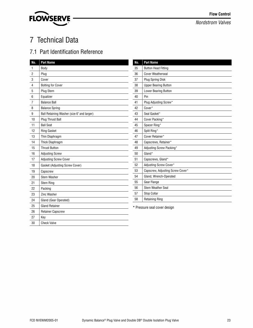
Flow Control
Nordstrom Valves
FCD NVENIM2005-01 Dynamic Balance® Plug Valve and Double DB® Double Isolation Plug Valve 23
7 Technical Data7.1 Part Identification Reference
No. Part Name
1 Body
2 Plug
3 Cover
4 Bolting for Cover
5 Plug Stem
6 Equalizer
7 Balance Ball
8 Balance Spring
9 Ball Retaining Washer (size 6" and larger)
10 Plug Thrust Ball
11 Ball Seat
12 Ring Gasket
13 Thin Diaphragm
14 Thick Diaphragm
15 Thrust Button
16 Adjusting Screw
17 Adjusting Screw Cover
18 Gasket (Adjusting Screw Cover)
19 Capscrew
20 Stem Washer
21 Stem Ring
22 Packing
23 Zinc Washer
24 Gland (Gear Operated)
25 Gland Retainer
26 Retainer Capscrew
27 Key
30 Check Valve
No. Part Name
35 Button Head Fitting
36 Cover Weatherseal
37 Plug Spring Disk
38 Upper Bearing Button
39 Lower Bearing Button
40 Pin
41 Plug Adjusting Screw*
42 Cover*
43 Seal Gasket*
44 Cover Packing*
45 Spacer Ring*
46 Split Ring*
47 Cover Retainer*
48 Capscrews, Retainer*
49 Adjusting Screw Packing*
50 Gland*
51 Capscrews, Gland*
52 Adjusting Screw Cover*
53 Capscrew, Adjusting Screw Cover*
54 Gland, Wrench-Operated
55 Gear Flange
56 Stem Weather Seal
57 Stop Collar
58 Retaining Ring
* Pressure seal cover design

Flow Control
Nordstrom Valves
24 Dynamic Balance® Plug Valve and Double DB® Double Isolation Plug Valve FCD NVENIM2005-01
7.2 Exploded ViewsFigure 4 – Wrench-Operated Valve

Flow Control
Nordstrom Valves
FCD NVENIM2005-01 Dynamic Balance® Plug Valve and Double DB® Double Isolation Plug Valve 25
7.3 Detail SketchesFigure 5 – Stem End Detail: Wrench-Operated Valve
5
26
22, 23
21
35
30
8
2
58
57
54
56
20*
6
7
1
*Applies to Size 6 and Larger only. Refer to Figure 7.Figure 6 – Stem End Detail: Gear-Operated with Bolt-on Gear Flange
1
30
8
7
6
2
35
55
26
5
21
22
23
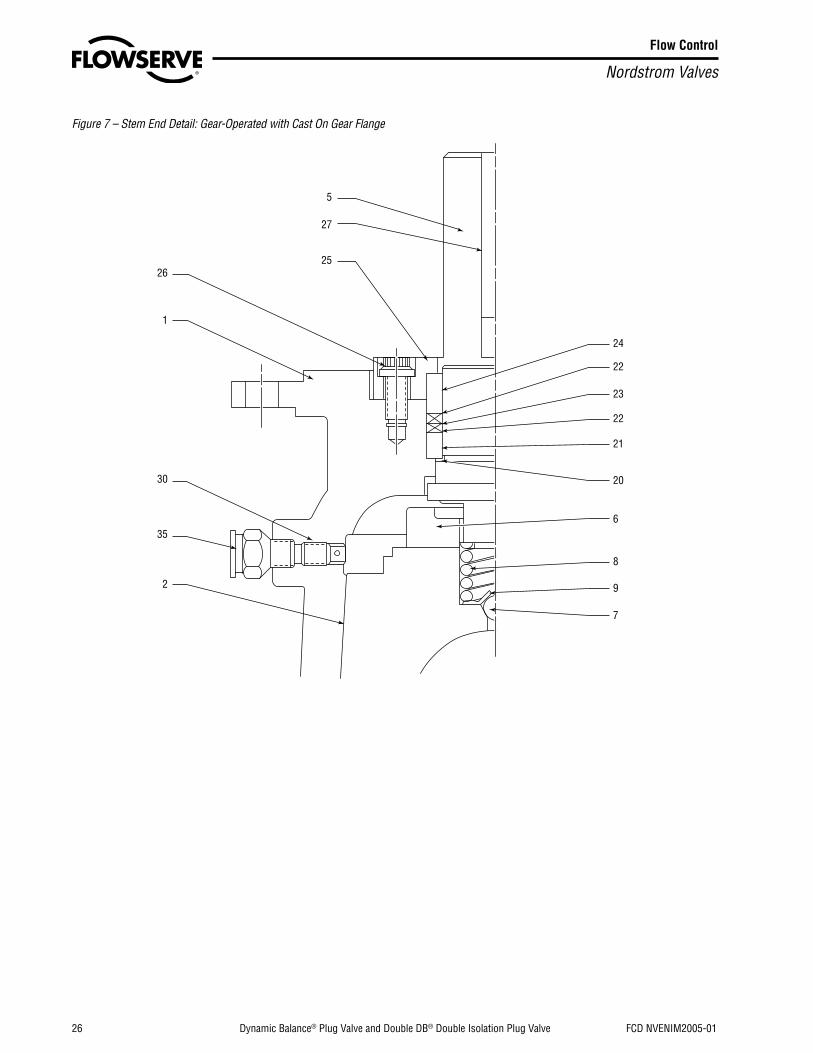
Flow Control
Nordstrom Valves
26 Dynamic Balance® Plug Valve and Double DB® Double Isolation Plug Valve FCD NVENIM2005-01
Figure 7 – Stem End Detail: Gear-Operated with Cast On Gear Flange
5
27
2526
1
30
35
2
24
22
23
22
21
20
6
8
9
7

Flow Control
Nordstrom Valves
FCD NVENIM2005-01 Dynamic Balance® Plug Valve and Double DB® Double Isolation Plug Valve 27
Figure 8 – Cover End Detail: Size 6 and Larger with Pressure Seal Arrangement
2
1
42
44
43
45
46
47
48
37
38
40
39
41
49
49
50
51
52
53
Figure 9 – Cover End Detail: Size 6 and Larger with Spring Disk Arrangement

Flow Control
Nordstrom Valves
28 Dynamic Balance® Plug Valve and Double DB® Double Isolation Plug Valve FCD NVENIM2005-01
Figure 10 – Cover End Detail: Size 6 and Larger with Ball Seat Arrangement
Figure 11 – Cover End Detail: Size 4 and Smaller
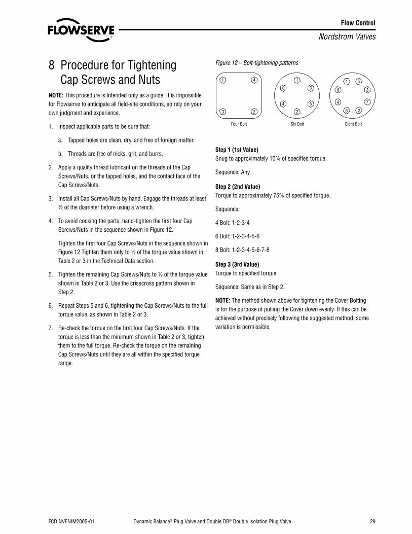
Flow Control
Nordstrom Valves
FCD NVENIM2005-01 Dynamic Balance® Plug Valve and Double DB® Double Isolation Plug Valve 29
8 Procedure for Tightening Cap Screws and Nuts
NOTE: This procedure is intended only as a guide. It is impossible for Flowserve to anticipate all field-site conditions, so rely on your own judgment and experience.
1. Inspect applicable parts to be sure that:
a. Tapped holes are clean, dry, and free of foreign matter.
b. Threads are free of nicks, grit, and burrs.
2. Apply a quality thread lubricant on the threads of the Cap Screws/Nuts, or the tapped holes, and the contact face of the Cap Screws/Nuts.
3. Install all Cap Screws/Nuts by hand. Engage the threads at least 1/2 of the diameter before using a wrench.
4. To avoid cocking the parts, hand-tighten the first four Cap Screws/Nuts in the sequence shown in Figure 12.
Tighten the first four Cap Screws/Nuts in the sequence shown in Figure 12.Tighten them only to 1/2 of the torque value shown in Table 2 or 3 in the Technical Data section.
5. Tighten the remaining Cap Screws/Nuts to 1/2 of the torque value shown in Table 2 or 3. Use the crisscross pattern shown in Step 2.
6. Repeat Steps 5 and 6, tightening the Cap Screws/Nuts to the full torque value, as shown in Table 2 or 3.
7. Re-check the torque on the first four Cap Screws/Nuts. If the torque is less than the minimum shown in Table 2 or 3, tighten them to the full torque. Re-check the torque on the remaining Cap Screws/Nuts until they are all within the specified torque range.
Figure 12 – Bolt-tightening patterns
Step 1 (1st Value)Snug to approximately 10% of specified torque.
Sequence: Any
Step 2 (2nd Value)Torque to approximately 75% of specified torque.
Sequence:
4 Bolt: 1-2-3-4
6 Bolt: 1-2-3-4-5-6
8 Bolt: 1-2-3-4-5-6-7-8
Step 3 (3rd Value)Torque to specified torque.
Sequence: Same as in Step 2.
NOTE: The method shown above for tightening the Cover Bolting is for the purpose of pulling the Cover down evenly. If this can be achieved without precisely following the suggested method, some variation is permissible.

Flow Control
Nordstrom Valves
30 Dynamic Balance® Plug Valve and Double DB® Double Isolation Plug Valve FCD NVENIM2005-01
9 TablesTorque Values for Pressure Retaining Bolting
Table 1– Size 4 and Smaller Valve Gland Bolting
Bolt Size 1stTorque (ft-lb)
2nd 3rd3⁄8 - 16 UNC Hand Snug 15 25
1/2 - 13 UNC Hand Snug 40 555⁄8 - 11 UNC Hand Snug 80 110
Table 2 – Size 4 and Smaller Valve Cover Bolting
Bolt SizeTorque (ft-lb)
1st 2nd 3rd3⁄8 – 11 UNC 20 85 110
3/4 – 10 UNC 20 135 1807⁄8 – 9 UNC 30 220 290
1 – 8 UNC 45 340 450
11⁄8 – 8 UNC 70 530 705
11/4 – 8 UNC 90 675 900
Table 3 – Size 6 and Larger Valve Pressure Retaining Bolting (all parts)
Thread SizeTorque (ft-lb)
Minimum Maximum
1/4 – 20 5 65⁄16 - 18 10 123⁄8 – 16 15 187⁄16 – 14 25 30
1/2 – 13 38 459⁄16 – 12 58 685⁄8 – 11 76 90
3/4 – 10 127 1507⁄8 – 9 205 240
1 – 8 315 370
11⁄8 – 8 500 585
11/4 – 8 640 750
13⁄8 – 8 870 1020
11/2 – 8 1010 1200
15⁄8 – 8 1400 1650
13/4 – 8 1900 2250
17⁄8 – 8 2550 3000
2 – 8 2800 3300
21/4 – 8 4000 4900
21/2 – 8 5500 5800
23/4 – 8 7400 9100

Flow Control
Nordstrom Valves
FCD NVENIM2005-01 Dynamic Balance® Plug Valve and Double DB® Double Isolation Plug Valve 31
Plug Adjusting Screw Torque ValuesThe torque values listed in the following table are based on the torque used during assembly of Dynamic Balance Plug Valves at the factory. Estimations of accurate torque values for the countless varieties of field site conditions, valve conditions, and sealant used are not feasible. Judgment and experience must be exercised when using this information for specific valves at your site.
Table 4 – Plug Adjusting Screw Torque ValuesValve Size Basic Figure Numbers Initial ft-lb Final
ft-lb
1/2 - 12245, 3045, 20545 65 – 75 5 – 8
6804, 6814, 6824 65 – 75 5 – 7
11/2 & 2
1945, 2045, 2245, 3045, 76205, 76305, 5345, 5545, 5645, 5845, 6345, 6545, 6645, 6845
105 – 125 5 – 8
20545, 76505, 5945, 6945 105 – 125 5 – 10
6804, 6814 150 – 175 10 – 17
6824, 6405, 6415 150 – 175 10 – 16
21/2 & 3
1945, 2045, 2245, 2345, 3045, 76205, 76305, 5345, 5545, 5645, 5745, 5845, 6345, 6545, 6645, 6745, 6845
150 – 175 9 – 16
20545, 76505, 5945, 6945 150 – 175 8 – 13
6405, 6415, 5205, 5215 150 – 175 22 – 36
5225 150 – 175 20 – 33
4
1945, 2045, 2245, 2345, 3045, 76205, 76305, 5345, 5545, 5645, 5745, 5845, 6345, 6545, 6645, 6745, 6845
150 – 175 12 – 20
20545, 76505, 5945, 6945, 32049 150 – 175 11 – 19
6405, 6415 150 – 175 22 – 36
5225 150 – 175 20 – 33
6
1945, 1949, 2045, 2049 40 4
2245, 2249, 4745, 4749, 5349, 5549, 5649, 6349, 6549, 6649 42 4
2349, 5749, 6749 58 6
3049, 6049, 5849, 6849 75 8
4245, 4249 70 7
4445, 4449 30 3
20549, 5949, 6949 65 6
8
1945, 1949, 2045, 2049 57 6
2249 145 15
2349, 5749, 6749 142 14
3049, 4749 75 8
4245, 4249, 4445, 4449 70 7
6049 132 13
Table 4 – Plug Adjusting Screw Torque Values (continued)Valve Size Basic Figure Numbers Initial ft-lb Final
ft-lb
10
1949, 2045, 2049 147 15
2249 190 19
2349 195 20
3049, 6049, 5849, 6849 630 63
4249 220 22
4449, 4749 210 21
20549 450 45
12
1949 330 33
2249 710 71
2349 730 73
4249 260 26
4449, 4749 300 30
6049, 9349, 5849, 6849, 5949, 6949 630 63
14
4149, 4249 430 43
4749 610 61
6049 770 77
16
4149, 4249, 4449, 4749 710 71
4949 910 91
6049 770 77
9349 1010 101
18
4149 740 74
4249, 4449 900 90
4749 930 93
4949 910 91
6049 1090 109
20
4149 800 80
4249, 4449 850 85
4749 1050 105
4949 1070 107
6049 1090 109
24
4149 1170 117
4249, 4449 1210 121
4749 1350 135
4949 1070 107
6049 1090 109
304149 1770 177
4249, 4449, 4749 1890 189

Flow Control
Nordstrom Valves
32 Dynamic Balance® Plug Valve and Double DB® Double Isolation Plug Valve FCD NVENIM2005-01
Sealant CapacitiesThe following information is intended only as a guide to assist you in determining the approximate amount of sealant that is required to service a valve with sealant.
The capacities shown are for valves that are empty of sealant.
Table 5 – Sealant Capacities
Valve Size Basic Figure Numbers Quarts of Sealant
No. of Gun Packs
No. of J Sticks
No. of 5-Quart Cans
No. of 5-Gal. Pails
1/2 - 12245 & 3045 .15 .59 .56 .03 .01
20545 .25 .98 .94 .05 .01
11/2 & 2 1945, 2045, 2245, 3045 & 20545 .25 .98 .94 .05 .01
21/2 & 3 1945, 2045, 2245, 2345, 3045 & 20545 .50 1.97 1.87 .10 .02
41945, 2045, 2145 & 2245 .50 1.97 1.87 .10 .02
2345, 3045 & 20545 .60 2.36 2.25 .12 .03
6
1945, 1949, 2245, 2249, 2349, 4245, 4249 2.00 7.87 7.49 .4 .10
4445, 4449, 4745 & 4749 2.00 7.87 7.49 .4 .10
3049 & 20549 3.00 11.81 11.23 .6 .15
81945, 1949, 2045, 2049, 2249, 2349, 3049 3.00 11.81 11.23 .6 .15
4245, 4249, 4445, 4449, 4749 & 20549 3.00 11.81 11.23 .6 .15
101945, 1949, 2045, 2049, 2249, 2349, 4249 3.00 11.81 11.23 .6 .15
4449, 4749 & 20549 3.00 11.81 11.23 .6 .15
121949, 4249, 4449 & 4749 3.00 11.81 11.23 .6 .15
2249, 2349 & 9349 4.00 15.74 14.98 .8 .20
14 & 16 4149, 4249, 4449 & 4749 4.00 15.74 14.98 .8 .20
164149, 4249, 4449 & 4749 4.00 15.74 14.98 .8 .20
9349 5.00 19.69 18.72 1.00 .25
18 4149, 4249, 4749 5.00 19.69 18.72 1.00 .25
24 4149, 4249, 4749 6.00 23.62 22.46 1.20 .30
30 4149, 4249, 4749 7.00 27.57 26.21 1.40 .35

Flow Control
Nordstrom Valves
FCD NVENIM2005-01 Dynamic Balance® Plug Valve and Double DB® Double Isolation Plug Valve 33
Flow Control
Nordstrom Valves
34 Dynamic Balance® Plug Valve and Double DB® Double Isolation Plug Valve FCD NVENIM2005-01

Flow Control
Nordstrom Valves
FCD NVENIM2005-01 Dynamic Balance® Plug Valve and Double DB® Double Isolation Plug Valve 35

Flowserve Corporation has established industry leadership in the design and manu-facture of its products. When properly selected, this Flowserve product is designed to perform its intended function safely during its useful life. However, the purchaser or user of Flowserve products should be aware that Flowserve products might be used in numerous applications under a wide variety of industrial service conditions. Although Flowserve can (and often does) provide general guidelines, it cannot provide specific data and warnings for all possible applications. The purchaser/user must therefore assume the ultimate responsibility for the proper sizing and selection, installation, op-eration, and maintenance of Flowserve products. The purchaser/user should read and understand the Installation Operation Maintenance (IOM) instructions included with the product, and train its employees and contractors in the safe use of Flowserve products in connection with the specific application.
While the information and specifications contained in this literature are believed to be accurate, they are supplied for informative purposes only and should not be considered certified or as a guarantee of satisfactory results by reliance thereon. Nothing contained herein is to be construed as a warranty or guarantee, express or implied, regarding any matter with respect to this product. Because Flowserve is continually improving and upgrading its product design, the specifications, dimensions and information contained herein are subject to change without notice. Should any question arise concerning these provisions, the purchaser/user should contact Flowserve Corporation at any one of its worldwide operations or offices.
For more information about Flowserve Corporation, visit www.flowserve.com or call USA 1-800-225-6989.
Flowserve CorporationNordstrom Valves1511 Jefferson StreetSulphur Springs, TX 75482USA
Phone: (903) 885-4691 (903) 885-4693(800) 225-6989
Fax: (903) 439-3411
Latin AmericaPhone: (903) 439-3407Fax: (903) 439-3411
All other countriesPhone: (903) 885-4692Fax: (903) 439-3404
Nordstrom Valves
© 2011 Flowserve Corporation, Irving, Texas, USA. Flowserve is a registered trademark of Flowserve Corporation. FCD NVENIM2005-01 Printed in USA.(Part V170-PED)