Embed Size (px)
Citation preview

6089
ISSN 2286-4822
www.euacademic.org
EUROPEAN ACADEMIC RESEARCH
Vol. IV, Issue 7/ October 2016
Impact Factor: 3.4546 (UIF)
DRJI Value: 5.9 (B+)
Dynamic Analysis of High Rise Building Structure
with Shear Walls at the Centre Core
DR. HADI HOSSEINI
Aerospace Engineering
Director at International Earthquake Research Center of America
(IERCA)
Abstract:
In present work, Forty storey buildings (120m) have been
modeled using software ETABS by dynamic analysis. All the analyses
has been carried out as per the Indian Standard code books. Based on
the literature of previous studies most effective positioning of shear
walls has been chosen. This study is done on RC framed multistory
building with RC shear walls with fixed support conditions. The
usefulness of shear walls in the structural planning of multistory
buildings has long been recognized. When walls are situated in
advantageous positions in a building, they can be very efficient in
resisting lateral loads originating from wind or earthquakes.
Incorporation of shear wall has become inevitable in multi-storey
building to resist lateral forces. This paper aims to study the behaviour
of reinforced concrete building by conducting dynamic analysis for
most suited positions and location of shear wall. Estimation of
structural response such as, storey displacements, base shear, storey
drift is carried out. Dynamic responses under zone V earthquake as per
IS 1893 (part 1): 2002 have been carried out. In dynamic analysis,
Response Spectrum method is used.
Key words: shear wall, storey displacements, base shear, storey drift,
Response Spectrum method, multi-storey building, lateral loads

Hadi Hosseini- Dynamic Analysis of High Rise Building Structure with Shear
Walls at the Centre Core
EUROPEAN ACADEMIC RESEARCH - Vol. IV, Issue 7 / October 2016
6090
INTRODUCTION:
Background
Reinforced concrete (RC) buildings often have vertical plate-like
RC walls called Shear Walls in addition to slabs, beams and
columns. These walls generally start at foundation level and
are continuous throughout the building height. Their thickness
can be as low as 150mm, or as high as 400mm in high rise
buildings. Shear walls are usually provided along both length
and width of buildings. Shear walls are like vertically-oriented
wide beams that carry earthquake loads downwards to the
foundation. Properly designed and detailed buildings with
shear walls have shown very good performance in past
earthquakes. The overwhelming success of buildings with shear
walls in resisting strong earthquakes is summarised in the
quote:“We cannot afford to build concrete buildings meant to
resist severe earthquakes without shear walls.”:: Mark Fintel, a
noted consulting engineer in USA. In modern tall buildings,
shear walls are commonly used as a vertical structural element
for resisting the lateral loads that may be induced by the effect
of wind and earthquakes. Shear walls of varying cross sections
i.e. rectangular shapes to more irregular cores such as channel,
T, L, barbell shape, box etc. can be used.
Essentials of Structural Systems for Seismic Resistance
The primary purpose of all structural members used in
buildings is to support gravity loads. However, buildings may
also be subjected to lateral forces due to wind and earthquakes.
The effects of lateral forces in buildings will be more significant
as the building height increases. All structural systems will not
behave equally under seismic excitation. Aspects of structural
configuration, symmetry, mass distribution and vertical
regularity must be considered. In addition to that, the
importance of strength, stiffness and ductility in relation to
Hadi Hosseini- Dynamic Analysis of High Rise Building Structure with Shear
Walls at the Centre Core
EUROPEAN ACADEMIC RESEARCH - Vol. IV, Issue 7 / October 2016
6091
acceptable response must be evaluated in structural system
(Paulay and Priestley, 1992).
METHODOLOGY:
Earthquake motion causes vibration of the structure leading to
inertia forces. Thus a structure must be able to safely transmit
the horizontal and the vertical inertia forces generated in the
super structure through the foundation to the ground. Hence,
for most of the ordinary structures, earthquake-resistant design
requires ensuring that the structure has adequate lateral load
carrying capacity. Seismic codes will guide a designer to safely
design the structure for its intended purpose.
1- Dynamic analysis.
I. Response spectrum method.
II. Time history method.
Dynamic Analysis
Dynamic analysis shall be performed to obtain the design
seismic force, and its distribution in different levels along the
height of the building, and in the various lateral load resisting
element, for the following buildings:
Regular buildings: Those greater than 40m in height in zones
IV and V, those greater than 90m in height in zone II and III.
Irregular buildings: All framed buildings higher than 12m in
zones IV and V, and those greater than 40m in height in zones
II and III.
The analysis of model for dynamic analysis of buildings
with unusual configuration should be such that it adequately
models the types of irregularities present in the building
configuration. Buildings with plan irregularities, as defined in
Table 4 of IS code: 1893-2002 cannot be modeled for dynamic
analysis. Dynamic analysis may be performed either by the
Hadi Hosseini- Dynamic Analysis of High Rise Building Structure with Shear
Walls at the Centre Core
EUROPEAN ACADEMIC RESEARCH - Vol. IV, Issue 7 / October 2016
6092
Time History Method or by the Response Spectrum Method
.However in either method, the design base shear VB shall be
compared with a base shear VB calculated using a fundamental
period Ta. When VB is less than VB all the response quantities
shall be multiplied by VB /Vb The values of damping for a
building may be taken as 2 and 5 percent of the critical, for the
purpose of dynamic analysis of steel and reinforced concrete
buildings, respectively.
Time History Method
The usage of this method shall be on an appropriate ground
motion and shall be performed using accepted principles of
dynamics. In this method, the mathematical model of the
building is subjected to accelerations from earthquake records
that represent the expected earthquake at the base of the
structure.
Response Spectrum Method
The word spectrum in engineering conveys the idea that the
response of buildings having a broad range of periods is
summarized in a single graph. This method shall be performed
using the design spectrum specified in code or by a site-specific
design spectrum for a structure prepared at a project site. The
values of damping for building may be taken as 2 and 5 percent
of the critical, for the purposes of dynamic of steel and reinforce
concrete buildings, respectively. For most buildings, inelastic
response can be expected to occur during a major earthquake,
implying that an inelastic analysis is more proper for design.
However, in spite of the availability of nonlinear inelastic
programs, they are not used in typical design practice because:
1- Their proper use requires knowledge of their inner
workings and theories. design criteria, and
2- Result produced are difficult to interpret and apply to
traditional design criteria , and
3- The necessary computations are expensive.

Hadi Hosseini- Dynamic Analysis of High Rise Building Structure with Shear
Walls at the Centre Core
EUROPEAN ACADEMIC RESEARCH - Vol. IV, Issue 7 / October 2016
6093
Therefore, analysis in practice typically use linear elastic
procedures based on the response spectrum method. The
response spectrum analysis is the preferred method because it
is easier to use.
NUMERICAL ANALYSES:
Structural Modeling of Building
Due to time limitations, it was impossible to account accurately
for all aspects of behavior of all the components and materials
even if their sizes and properties were known. Thus, for
simplicity, following assumptions were made for the structural
modeling:
1. The materials of the structure were assumed as
homogeneous, isotropic and linearly elastic.
2. The effects of secondary structural components and
non structural components such as staircase, masonry
infill walls were assumed to be negligible.
3. Floors slabs were assumed rigid in plane.
4. Foundation for analysis was considered as rigid.
Beams and columns were modeled as frame elements. Shear
walls were modeled as plate elements. Floor slabs were
modeled as rigid horizontal plane.
Details of the Building
A symmetrical building of plan 24.5m X 22.5m located with
location in zone V, India is considered. Seven bays of length
3.5m along X - direction and five bays of length 4.5m along Y -
direction are provided. Shear Wall is provided at the center core
of the building model.

Hadi Hosseini- Dynamic Analysis of High Rise Building Structure with Shear
Walls at the Centre Core
EUROPEAN ACADEMIC RESEARCH - Vol. IV, Issue 7 / October 2016
6094
Table I: Details of the building
Structural Analysis
Initial dimensions of the structural elements for the buildings
were assumed on the basis of gravity loads and imposed loads.
Since, the buildings were assumed as apartment buildings,
imposed load of 2 kN/m2 and load due to floor finish were taken
as 1.0 kN/m2 as per Indian Standard, IS 875 (part2) : 1987.
Lateral loads due to earthquake (EL) were calculated
considering full dead load (DL) plus 25% of imposed load (IL),
using seismic coefficient method given in IS 1893 (Part 1) :
2002.Since the buildings were assumed as apartment buildings
with dual system (shear wall and special moment resisting
frame) situated in seismic zone V, importance factor (I) = 1,
zone factor (Z) = 0.36 and response reduction factor (R) = 5 as
given in IS code were used for lateral load calculations.

Hadi Hosseini- Dynamic Analysis of High Rise Building Structure with Shear
Walls at the Centre Core
EUROPEAN ACADEMIC RESEARCH - Vol. IV, Issue 7 / October 2016
6095
Assuming medium type of soil on which the foundations rest
and the damping ratio of 5% for concrete structure, average
response acceleration coefficient (Sa/g) was obtained from IS
code, depending on the approximate fundamental natural time
period of the structure estimated. Assuming the floor is capable
of providing rigid diaphragm action, total shear in any
horizontal plane is distributed to the various vertical elements
according to their relative stiffness. After several analyses in
ETABS using equivalent static lateral force analysis for various
load combinations given in IS 1893 (Part 1): 2002, final
dimensions of the structural elements for further analyses of
the buildings were obtained. The maximum percentage of
reinforcements for structural elements was limited to 4% of
concrete gross area as per IS 456 : 2000. Concrete grade of M30
i.e. characteristic compressive strength (fck) of 30 N/mm2 was
assumed for all structural elements. Material properties were
assumed same for all structural elements used in both all the
buildings. The material properties assumed for final structural
analysis are as follows:
Modulus of elasticity (Ε) = 2.5×10⁷ kN/m2
Poisson’s ratio (ν) = 0.17
Unit weight of concrete (γ) = 25 kN/m3

Hadi Hosseini- Dynamic Analysis of High Rise Building Structure with Shear
Walls at the Centre Core
EUROPEAN ACADEMIC RESEARCH - Vol. IV, Issue 7 / October 2016
6096
Layout of the Buildings
Figure 1, Plan of the building Figure2, 3D view of the building
Building Design Requirements
The proposed reinforced concrete shear wall buildings are
located in zone V, India. Code requirements from IS 456 : 2000,
IS 13920 : 1993 and IS 1893 (part 1) : 2002 were used for
structural design.
In the ETABS design model, modeling was done in order
to verify sufficient strength and stiffness. Rigid diaphragms,
along with lumped masses, were assigned at each level.

Hadi Hosseini- Dynamic Analysis of High Rise Building Structure with Shear
Walls at the Centre Core
EUROPEAN ACADEMIC RESEARCH - Vol. IV, Issue 7 / October 2016
6097
Load combinations
As per IS 1893 (Part 1): 2002 Clause no. 6.3.1.2, the following
load cases have to be considered for analysis:
1.5 (DL + IL)
1.2 (DL + IL ± EL)
1.5 (DL ± EL)
0.9 DL ± 1.5 EL
Earthquake load must be considered for +X, -X, +Y and –Y
directions.
Design of beams
The flexural members shall fulfil the following general
requirements. (IS 13920; Clause 6.1.2)
In the present study beam of size (230 X 450) mm has been
used.
Here,
=
= 0.51 0.3.
Hence, ok.
As per IS 13920; Clause 6.1.3
b ≥ 200 mm
Here b = 300 mm ≥ 200 mm
Hence, ok.
As per IS 13920; Clause 6.1.4
The depth D of the member shall preferably be not more than ¼
of the clearspan.
Here, D=450 mm and clear span length is 3000 mm.
¼ (clear span) = 3000/4 =750 mm 450 mm
Hence, ok.
Check for reinforcement
As per IS 13920; Clause 6.2.1 (b)
The tension steel ratio on any face, at any section, shall not be
less than 0.24 /fy
Therefore, = 0.361 %

Hadi Hosseini- Dynamic Analysis of High Rise Building Structure with Shear
Walls at the Centre Core
EUROPEAN ACADEMIC RESEARCH - Vol. IV, Issue 7 / October 2016
6098
As per IS 13920; Clause 6.2.2
The maximum steel ratio on any face at any section, shall not
exceed 0.025 or 2.5 %.
Design was carried out by the software and values for
critical members were noted down as follows;
Table (1) values of most critical member of building model.
Building Model values
Model
2.38
Therefore, the model pass the reinforcement check.
Design of columns
Check for axial stress
As per IS 13920; Clause 6.1.1
The factored axial stress on the member under earthquake
loading shall not exceed 0.1 (=3 Mpa)
The factored axial stress values for the most critical member of
each model were noted down as follows;
Table (2) Axial stress values of most critical member of building
model.
Building Model
Model
5.41
The model does not satisfy the above clause. However, IS 13920
specifies another clause for this case.
Design requirements which have axial stress in excess of
0.1
In the present study, the minimum dimension of the member
provided is 500 mm. Also the shortest dimension provided is
500 mm. As per IS 13920; Clause 7.1.2, the minimum
dimension of the member shall not be less than 200 mm.

Hadi Hosseini- Dynamic Analysis of High Rise Building Structure with Shear
Walls at the Centre Core
EUROPEAN ACADEMIC RESEARCH - Vol. IV, Issue 7 / October 2016
6099
Hence the above clause is in fulfillment of the building models.
Two types of columns were provided in the present study.
Column 1 has a cross section of 400 X 700 mm while Column 2
has 500 X 500 mm
Column 1; 400/700 =0.57 0.4.
Column 2; 500/500 = 1 0.4
As per IS 13920; Clause 7.1.3, the ratio of the shortest cross
sectional dimension to the perpendicular dimension shall
preferably not be less than 0.4.
Hence, both the columns satisfy the clause.
The column section shall be designed just above and just below
the beam column joint, and larger of the two reinforcements
shall be adopted. This is similar to what is done for design of
continuous beam reinforcements at the support. The end
moments and end shears are available from computer analysis.
The design moment should include:
(a) The additional moment if any, due to long column effect as
per clause 39.7 of IS 456:2000.
(b) The moments due to minimum eccentricity as per clause
25.4 of IS 456:2000.
The longitudinal reinforcements are designed as per IS 456 :
2000
Reinforcement check:
Design was carried out by the software and values for
critical members were noted down as follows;
Table (3) values of most critical member of building model
Building Model
values
Model
3.61
As per IS 456 : 2000; Clause 26.5.3.1(a) the cross sectional area
of longitudinal reinforcement, shall not be less than 0.8 % nor
more than 6 % of the gross cross sectional area of the column. It
should be noted that percentage of steel should not exceed 4 %
Hadi Hosseini- Dynamic Analysis of High Rise Building Structure with Shear
Walls at the Centre Core
EUROPEAN ACADEMIC RESEARCH - Vol. IV, Issue 7 / October 2016
6100
since it may involve practical difficulties. Therefore, all the
models pass the reinforcement check.
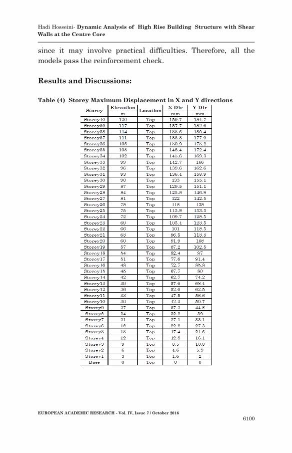
Results and Discussions:
Table (4) Storey Maximum Displacement in X and Y directions
Hadi Hosseini- Dynamic Analysis of High Rise Building Structure with Shear
Walls at the Centre Core
EUROPEAN ACADEMIC RESEARCH - Vol. IV, Issue 7 / October 2016
6101
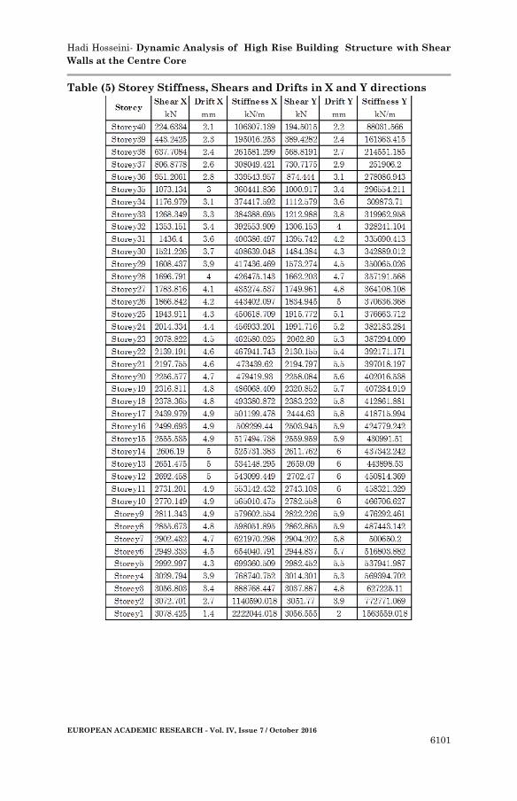
Table (5) Storey Stiffness, Shears and Drifts in X and Y directions

Hadi Hosseini- Dynamic Analysis of High Rise Building Structure with Shear
Walls at the Centre Core
EUROPEAN ACADEMIC RESEARCH - Vol. IV, Issue 7 / October 2016
6102
Table (6) Modes and periods
Here the minimum modal mass for
accelerations Ux and Uy is 93.48 %
and 93.99 % respectively.
Mode Shape
Figure3, Mode shape for model
Storey Maximum Displacements
Table (7) Maximum Storey
Displacements in X Direction for
model
All values are in mm

Hadi Hosseini- Dynamic Analysis of High Rise Building Structure with Shear
Walls at the Centre Core
EUROPEAN ACADEMIC RESEARCH - Vol. IV, Issue 7 / October 2016
6103
COMPARISON OF RESULTS:
Storey Maximum Displacements
Table (8) Maximum Storey
Displacements in Y Direction
for model
All values are in mm
Table (9) Storey drifts in X
direction
All values are in mm

Hadi Hosseini- Dynamic Analysis of High Rise Building Structure with Shear
Walls at the Centre Core
EUROPEAN ACADEMIC RESEARCH - Vol. IV, Issue 7 / October 2016
6104
Table (10) Storey drifts in Y direction
All values are in mm

Hadi Hosseini- Dynamic Analysis of High Rise Building Structure with Shear
Walls at the Centre Core
EUROPEAN ACADEMIC RESEARCH - Vol. IV, Issue 7 / October 2016
6105
As per Indian standard, Criteria for earthquake resistant
design of structures, IS 1893 (Part 1): 2002, the story drift in
any story due to service load shall not exceed 0.004 times the
story height.
The height of the each storey is 3 m. So, the drift
limitation as per IS 1893 (part 1): 2002 is 0.004 X 3 m = 12 mm.
The model show a similar behaviour for storey drifts as shown
in graph.
Base Shears
Table (11) Base shears in X&Y direction
Model Base Shears in X (kN)
Model 3078.425
Model Base Shears in Y(kN)
Model 3056.555
Modal Results
Table (12) Modes and natural periods
Table (13) Modal Masses
Natural
Periods(sec
)
Modal 1 6.669
Modal 2 6.046
Modal 3 5.318
Modal 4 2.117
Modal 5 1.887
Modal 6 1.758
Modal 7 1.165
Modal 8 1.05
Modal 9 1.004
Modal 10 0.797
Modal 11 0.738
Modal 12 0.671
Case Mode
Model
Dynamic %
Acceleration Ux Acceleration Uy
Model 93.48 93.99

Hadi Hosseini- Dynamic Analysis of High Rise Building Structure with Shear
Walls at the Centre Core
EUROPEAN ACADEMIC RESEARCH - Vol. IV, Issue 7 / October 2016
6106
According to IS-1893:2002 the number of modes to be used in
the analysis should be such that the total sum of modal masses
of all modes considered is at least 90 percent of the total seismic
mass.
CONCLUSION AND RECOMMENDATIONS:
Conclusions
In this paper, reinforced concrete shear wall buildings were
analyzed with the procedures laid out in IS codes.
From the above results and discussions, following
conclusions can be drawn:
1. For both X and Y directions, the behaviour of the graph
is similar for the model as shown. The Maximum Storey
Displacement was observed for model at 159.7 mm and
184.7 mm in X and Y direction respectively. The order of
maximum storey displacement in both the directions for
model is same.
2. The location of shear walls in the outermost perimeter
considerably reduce the effects of displacements and
drifts.
3. Shear Walls must be coinciding with the centroid of the
building for better performance. It follows that a centre
core Shear wall should be provided.
4. Shear walls are more effective when located along
exterior perimeter of the building. Such a layout
increases resistance of the building to torsion.
5. Based on the analysis and discussion ,shear wall are
very much suitable for resisting earthquake induced
lateral forces in multistoried structural systems when
compared to multistoried structural systems whit out
shear walls. They can be made to behave in a ductile
manner by adopting proper detailing techniques.
6. The vertical reinforcement that is uniformly distributed
in the shear wall shall not be less than the horizontal

Hadi Hosseini- Dynamic Analysis of High Rise Building Structure with Shear
Walls at the Centre Core
EUROPEAN ACADEMIC RESEARCH - Vol. IV, Issue 7 / October 2016
6107
reinforcement .This provision is particularly for squat
walls (i.e. Height-to-width ratio is about 1.0).However
,for walls whit height-to-width ratio less than 1.0, a
major part of the shear force is resisted by the vertical
reinforcement. Hence ,adequate vertical reinforcement
should be provided for such walls.
7. Shear walls must provide the necessary lateral strength
to resist horizontal earthquake forces.
8. When shear walls are strong enough, they will transfer
these horizontal forces to the next element in the load
path below them, such as other shear walls, floors,
foundation walls, slabs or footings.
9. Shear walls also provide lateral stiffness to prevent the
roof or floor above from excessive side-sway.
Recommendations
Different assumptions and limitations have been adopted for
simplicity in modeling the proposed structures. In reality, it
might affect on results. Thus, all factors which may influence
on the behaviour of the structures should be considered in the
modeling. For the further study, to obtain the real responses of
the structures, the following recommendations are made:
1. Since the study was performed for only one type of shear
wall, the further investigations should be made for
different types of shear walls.
2. Further investigations should be done for shear walls
with different aspect ratio (h/L), in frame-shear wall
structures.
3. A flexible foundation will affect the overall stability of
the structure by reducing the effective lateral stiffness.
So the soil structure interaction should be considered in
further study.
4. Shear wall structure have been shown to perform well in
earthquakes, for which ductility becomes an important
consideration. Thus, further study should be made

Hadi Hosseini- Dynamic Analysis of High Rise Building Structure with Shear
Walls at the Centre Core
EUROPEAN ACADEMIC RESEARCH - Vol. IV, Issue 7 / October 2016
6108
considering geometric and material non-linear behavior
of the members concerned.
The study was performed for a damping ratio of 5% for all
models. Further studies should be carried out for damping
ratious of 10%, 15% and so on.
REFERENCES:
1. Anshuman, S., Dipendu Bhunia, Bhavin Ramjiyani,
“Solution of shear wall location in multistory building”,
International journal of civil and structural engineering,
2011.
2. Ashraf, M., Siddiqi, Z.A., Javed, M.A., “Configuration of
a multi- story building subjected to lateral forces”,
Asian journal of civil engineering, Vol. 9, No. 5, pp. 525-
537, 2008.
3. Agarwal, A.S., and Charkha, S.D., “Effect of change in
shear wall location on storey drift of multistorey building
subjected to lateral loads”, ISSN: 2248-9622 2(3), May-
Jun 2012.
4. Bureau of Indian Standars, IS 456: 2000, “Plain and
Reinforced Concrete-Code of practice”, New Delhi, India.
5. Bureau of Indian Standards: IS 13920: 1993, “Ductile
detailing of reinforced concrete structures subjected to
seismic forces— Code of Practice”, New Delhi, India.
6. Bureau of Indian Standards: IS 875(part 1): 1987, “Dead
loads on buildings and Structures”, New Delhi, India.
7. Bureau of Indian Standards: IS 875(part 2): 1987, “Live
loads on buildings and Structures”, New Delhi, India.
8. Bureau of Indian Standards: IS 1893 (part 1): 2002,
“Criteria for earthquake resistant design of structures:
Part 1 General provisions and buildings”, New Delhi,
India.
Hadi Hosseini- Dynamic Analysis of High Rise Building Structure with Shear
Walls at the Centre Core
EUROPEAN ACADEMIC RESEARCH - Vol. IV, Issue 7 / October 2016
6109
9. Chopra, A.K., “Dynamics of Structures: Theory and
Application to Earthquake Engineering”, Pearson
Education, 4th edition, 2012.
10. Duggal, S.K., “Earthquake Resistant Design of
Structures” Oxford University Press, New Delhi 2010
11. Paulay, T., Priestly, M.J.N., “Seismic Design of
Reinforced Concrete and Masonry Buildings”, ISBN:
978-0-471-54915-4, March 1992.
12. Rahangdale, H., Satone, S.R., “Design and analysis of
multi-storied building with effect of shear wall”,
International journal of engineering research and
application", Vol. 3, Issue 3, pp. 223-232, 2013.
13. Smith,B.S. and Coull, A., “Tall Building Structures:
Analysis & Design,” New York: John Wiley & Sons,
Inc.,1991.
Author’s Profile:
Dr. Hadi Hosseini, Aerospace Engineering,
Associate Professor in International
Earthquake Research Center of America
(IERCA) Email: [email protected]