Embed Size (px)
Citation preview

Acta Technica Jaurinensis
Vol. 8, No. 4, pp. 280-295, 2015 DOI: 10.14513/actatechjaur.v8.n4.379
Available online at acta.sze.hu
280
Dynamic Analysis of a One-cylinder Engine Crankshaft
P. Horváth, J. Égert
Department of Applied Mechanics, Faculty of Mechanical Engineering Information Technology and Electrical Engineering
Széchenyi István University 9026 Győr 1 Egyetem tér, Hungary
[email protected], [email protected] Abstract: The paper deals with the vibration analysis of a one-cylinder engine
crankshaft. For the analysis, a sequential torsional multi-mass vibration model was created of the crank-mechanism. The natural frequencies and natural modes of the crankshaft were determined from this model. The results of the torsional model were verified with a 3D finite element model, which consists of not only the torsional, but every other natural frequency and mode of the crankshaft. From the torsional natural frequencies and the harmonic expansion of the excitation forces, the critical speeds were determined, where resonance phenomena can occur. The relative angular deflection of the two ends of the crankshaft was also determined which characterizes the torsional stiffness of the crankshaft. From the angular velocity function of the clutch, the measure of speed irregularity of the clutch was defined.
Keywords: crankshaft, multi-mass model, vibration, natural frequency, natural mode
1. Introduction As result of periodic loading in time, every mechanism that contains elastic elements
– e.g. the crankshaft of an internal combustion engine – vibrations may occur. The investigated crank-mechanism can be regarded as a vibration system from a mechanical point of view. In this vibration system under specific conditions resonance phenomena may occur. In the analysis, the goals were: to perform a free vibration analysis of the crank-mechanism in order to obtain the
natural frequencies and natural modes of the crankshaft, to investigate the effect of the excitation loads, to determine critical speeds, where resonance phenomenon can occur, to define the relative angular deflection of the two ends of the crankshaft, which
is characteristic for the stiffness of the crankshaft, to define the measure of speed irregularity of the clutch, which has a great impact
on the fatigue life of the gearbox.
The investigation and clarification of the abovementioned points is crucial because of the constructional modifications [1]. Since the stiffness of the crankshaft has been

P. Horváth and J. Égert – Acta Technica Jaurinensis, Vol. 8, No. 4, pp. 280-295, 2015
281
reduced [1], the structure has become more sensitive to excitation loads, to vibration and to resonance phenomena. 2. Creating the torsional multi-mass model of the crank mechanism
For the torsional analysis of the crankshaft (Fig. 1.) a simple multi-mass model was created from the original crank-mechanism which only describes the torsional vibrations of the crankshaft.
1: flywheel 2: halfshaft (flywheel side) 3: main journal (flywheel side) 4: crankpin 5: web (flywheel side) 6: web (clutch side) 7: main journal (clutch side) 8: halfshaft (clutch side) 9: clutch 10: connecting rod 11: piston
Figure 1. Parts of the analysed crank mechanism
A seven-degree of freedom sequential multi-mass torsional model was created (Fig. 2.) for modelling the crank mechanism (Fig. 1.) according to [2], [3] and [4].
Figure 2. The sequential torsional multi-mass model of the crank mechanism
In this model, the rigid mass elements are described by moments of inertia and elastic elements are characterized by torsional stiffnesses. The unknown parameters, which should be calculated, are the angular deflections of the rigid mass elements. As the

P. Horváth and J. Égert – Acta Technica Jaurinensis, Vol. 8, No. 4, pp. 280-295, 2015
282
unknown parameters are only angular deflections, the mass properties can be given simply by moments of inertia. The main bearings of the crankshaft have no effect on the angular deflections, so the torsional multi-mass model has no kinematic boundary conditions, it is a so-called free vibration model. In order to create the torsional multi-mass model, the mass- and stiffness reduction of the crankshaft had to be performed.
2.1 Mass-reduction of the crankshaft
The moments of inertia for a simple shaft, journal or pin (parts 2, 3, 4, 7 and 8 in Fig. 1), calculated with respect to the rotational axis of the crankshaft, can be calculated as follows:
2 2
2 1
2 4 4
D dJ mr m
, (1)
where m is the mass of the given part, d is the inner diameter, D is the outer diameter of the part and r is the distance from the rotation-axis (in case of the crankpin, it is the throw of crank, in other cases it is zero).
The moments of inertia of the webs and counterweights were gained from the CAD model.
The moments of inertia of the connecting rod and piston reduced to the rotation-axis are function of the crank angle. In this case an equivalent moment of inertia was calculated according to [12]:
2
21
2 8e hA hB dJ m m m r
, (2)
where: - 1hA h hm u m is the rotating mass part of the connecting rod, where hu is
the length ratio of the big end - center of gravity distance to the big end - small end distance and hm is the mass of the connecting rod,
- hB h hm u m is the alternating mass part of the connecting rod,
- dm is the mass of the piston,
- r is the length of the throw of crank, - /r l is the length ratio of throw of crank to the connecting rod length
In Table 1. the moments of inertia of each mass element of the crank mechanism, obtained from the formulas (1) and (2) and CAD calculations [2] [3] are summarized.
From the ten moments of inertia in Table 1. seven moments of inertia were calculated by the formulas in Table 2., which are assumed to be mass elements in the ends of the shafts and in the middle of the pins (Fig. 2.). In Table 2. these seven moments of inertia and their derivation from the former ten moments of inertia shown in Table 1. are summarized.

P. Horváth and J. Égert – Acta Technica Jaurinensis, Vol. 8, No. 4, pp. 280-295, 2015
283
Table 1. Moments of inertia of the parts of the crank mechanism
Symbol of moment of inertia
Description of the part of the crank mechanism
Value of moment of inertia [kgm2]
Jl flywheel 2,906∙10-3
Jvt halfshaft (flywheel side) 6,57157∙10-6
Jvcs main journal (flywheel side) 1,44886∙10-5
Jvk web (flywheel side) 1,135432∙10-3
Jfcs crankpin 1,23428∙10-4
Jhk web (clutch side) 1,135622∙10-3
Jhcs main journal (clutch side) 1,57778∙10-5
Jht halfshaft (clutch side) 6,9956∙10-5
Jk clutch 6,206∙10-3
Je piston and connecting rod 4,343∙10-4
Table 2. The moments of inertia of the mass elements used for the torsional analysis
Symbol of mass element
Description of mass element
Calculation of moment of inertia of the mass elements
Moment of inertia Ji [kgm2]
i=1 flywheel 1 / 2l vtJ J J 2,910∙10-3
i=2 halfshaft 1 - main
journal 1 2 2vtJ
J 3,286∙10-6
i=3 main journal 1 3 / 2vcs vkJ J J 5,822∙10-4
i=4 crankpin 4 2 2vk hk
fcs e
J JJ J J 1,693∙10-3
i=5 main journal 2 5 / 2hcs hkJ J J 5,836∙10-4
i=6 main journal 2 -
halfshaft 2 6 2htJ
J 2,998∙10-5
i=7 clutch 7 / 2k htJ J J 6,206∙10-3
2.2 Stiffness-reduction of the crankshaft
For the sequential torsional vibration system, six elastic elements are needed between the above described seven reduced rigid mass elements. Fig. 3. shows these elastic elements of the crankshaft.
In case of shafts and pins, the stiffness can be calculated with the following formula:
pcsI GM
sl
, (3)
where pI is the polar moment of inertia of the cross section area, G is the shear
modulus of the crankshaft’s material and l is the length of the shaft / pin.

P. Horváth and J. Égert – Acta Technica Jaurinensis, Vol. 8, No. 4, pp. 280-295, 2015
284
Figure 3. The six elastic elements connecting the rigid mass elements.
In case of webs, the stiffness cannot be calculated with a simple formula. In this paper, the web’s stiffness was calculated with the aid of the AutoSHAFT modul of AVL Excite Designer software [2]. This modul automatically creates the FEM model of the crank web and then with static FEM analysis it calculates the torsional stiffness of the webs, applying a tentative torque on the webs. In Table 3. the stiffness of the elastic elements are summarized.
Table 3. Stiffnesses of the connecting elastic elements
Symbol of connecting element
Description of connecting element
Value of stiffness si [Nm/rad]
i=12 halfshaft 1 9,628∙104
i=23 half main journal 1 5,399∙105
i=34 web 1 1,766∙105
i=45 web 2 1,643∙105
i=56 half main journal 2 4,293∙105
i=67 halfshaft 2 2,024∙105
3. The natural frequencies and natural modes from the multi-mass model
A free sequentional torsional model consisting of n mass has (n-1) non zero natural frequencies and modes, so the above created multi-mass model consisting of seven mass elements has six non zero natural frequencies. The determination of the movement of this multi-mass model can be expressed using Lagrange’s equations [8]:
sii
d E EQ
dt
, (4)
where E is the kinetic energy of the whole torsional model, i is the angular deflection
of mass element i and SiQ is the spring force. Executing the differentiations in (4) the
following second order differential equation system is obtained:
0M K , (5)

P. Horváth and J. Égert – Acta Technica Jaurinensis, Vol. 8, No. 4, pp. 280-295, 2015
285
where is the vector of angular deflection (6) of the mass elements, M is the mass
matrix (7) and K is the stiffness matrix (8).
1 2 7...T (6)
1
2
3
4
5
6
7
0 0 0 0 0 0
0 0 0 0 0 0
0 0 0 0 0 0
0 0 0 0 0 0
0 0 0 0 0 0
0 0 0 0 0 0
0 0 0 0 0 0
J
J
J
M J
J
J
J
(7)
12 12
12 12 23 23
23 23 34 34
34 34 45 45
45 45 56 56
56 56 67 67
67 67
0 0 0 0 0
0 0 0 0
0 0 0 0
0 0 0 0
0 0 0 0
0 0 0 0
0 0 0 0 0
s s
s s s s
s s s s
K s s s s
s s s s
s s s s
s s
(8)
The differential equation system (4) leads to the (9) eigenvalue problem, the eigenvalues of which provide the natural circular frequencies i , while the eigenvectors
provide the natural modes 0 i for the natural circular frequency i
20 0 i i
K M . (9)
Table 4. The natural circular frequencies and natural frequencies of the multi-mass model
Natural circular frequencies (rad/s)
Natural frequencies (Hz)
ω1 3944,6 627,8
ω2 8857,4 1409,7
ω3 21934,6 3491,0
ω4 24975,0 3974,9
ω5 146949,3 23387,7
ω6 440913,7 70173,6
In Table 4. the natural circular frequencies and the natural frequencies are summarized, while Fig. 4. illustrates the first two natural modes, which belong to the lowest two natural frequencies. The natural modes illustrate the relative ratio and

P. Horváth and J. Égert – Acta Technica Jaurinensis, Vol. 8, No. 4, pp. 280-295, 2015
286
direction of the amplitudes of the angular deflection of the mass elements of the multi-mass model vibrating on the given natural frequency. The actual vibration amplitudes will be influenced by the excitation forces and the damping of the crank mechanism. It can be observed that the first natural mode has one non-vibrating (non-rotating) point, while the second mode has two, so the number of the non-vibrating points increases according to the number of the natural modes. In case of engines, in general, it is important to know only the first two natural modes, as the detectable harmonics of the excitation torques – as it will be seen in the next chapter – are only in the range of the first two natural frequencies.
Figure 4. First two natural modes of the crankshaft
4. The natural frequencies and natural modes calculated by FEM modeling
In this point the natural frequencies and natural modes will also be calculated by FEM method. In order to verify the result of the multi-mass model, these results will be compared to the former values.
For the vibration analysis of the FEM model, the Modal modul of ANSYS software [5] was used. From the crankshaft–flywheel–clutch assembly, the FEM model was created only for the crankshaft, the flywheel and the clutch were added as mass elements, characterized by their mass and their moments of inertia.
As a kinematic boundary condition in static analysis, an elastic support was used on the contact surface of the main bearings [1]. At free vibration analysis kinematic boundary condition does not need to be defined. In an eigenvalue problem dynamic boundary conditions (loadings) are not needed either.
The FEM analysis has covered only the first two natural frequences which are the most important ones from the resonance phenomena point of view [6] – [8]. Fig. 5.

P. Horváth and J. Égert – Acta Technica Jaurinensis, Vol. 8, No. 4, pp. 280-295, 2015
287
illustrates the first two natural modes belonging to the lowest two natural frequencies of the crankshaft.
Figure 5. The first two natural modes belonging to the lowest two natural frequencies
In Table 5. the first two natural frequencies of the FEM model are compared with the first two natural frequencies of the torsional multi-mass model.
Table 5. Comparison of the natural frequencies of the torsional multi-mass model with those of the FEM model
Natural frequencies of the multi-mass model (Hz)
Natural frequencies of the FEM model (Hz)
Relative error [%]
627,8 636,79 1,43
1409,7 1436,1 1,87
As can be seen from Table 5. the first two natural frequencies calculated from the torsional multi-mass model and those calculated from the FEM model show a very good match, the relative error is below 2 % in both cases. Furthermore, the natural modes obtained from the FEM model come close to those obtained from the multi-mass model. On the basis of this, it can be stated that from the torsional vibrations aspect, in the frequency range of operation, the multi–mass model comes close to the real system in respect to natural frequencies and natural modes.
5. Forced torsional vibrations
The periodic tangential force generates not only a static torque on the crankshaft, but it causes additional torsional vibrations as well. Both the tangential force – crank angle function and the torque – crank angle function, due to the periodical characteristic of these functions, they can be expanded into harmonic series. In course of the harmonic series development, the torque – crank angle function is expanded into an infinite series, where the terms of the series are harmonic (sine and cosine) functions. The harmonic expansion can be performed mathematically with the Fourier-Transformation. According to this, the torque – crank angle function ( )M can be written with the use
of harmonic functions as the following series [9]:
P. Horváth and J. Égert – Acta Technica Jaurinensis, Vol. 8, No. 4, pp. 280-295, 2015
288
1 1
2 2( ) 2 cos 2 sink n n
n n
M M a n b nT T
, (10)
where kM is the mean torque, while na and nb coefficients can be calculated with the
following formulas:
0
1 2( )cos
T
na M n dT T
,
0
1 2( )sin
T
nb M n dT T
. (11)
In case of a four stroke engine the whole engine cycle is 4T . Substituting this value into the equations (11), the argumentums of the sine and cosine functions will be
2
n , where 2
nx is the n-th order of the series development, which is the number of
harmonic oscillations during a whole engine cycle. So in case of a four stroke engine, the harmonics will have half orders, as in case of n = 1, 2, 3 we get x = 0,5, 1, 1,5 oscillation in the harmonic functions.
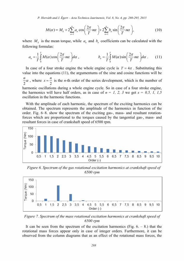
With the amplitude of each harmonic, the spectrum of the exciting harmonics can be obtained. The spectrum represents the amplitude of the harmonics in function of the order. Fig. 6–8. show the spectrum of the exciting gas-, mass- and resultant rotation-forces which are proportional to the torques caused by the tangential gas-, mass- and resultant forces in case of crankshaft speed of 6500 rpm.
Figure 6. Spectrum of the gas rotational excitation harmonics at crankshaft speed of 6500 rpm
Figure 7. Spectrum of the mass rotational excitation harmonics at crankshaft speed of 6500 rpm
It can be seen from the spectrum of the excitation harmonics (Fig. 6. – 8.) that the rotational mass forces appear only in case of integer orders. Furthermore, it can be observed from the column diagrams that as an effect of the rotational mass forces, the
P. Horváth and J. Égert – Acta Technica Jaurinensis, Vol. 8, No. 4, pp. 280-295, 2015
289
amplitude of the first order rotational gas force increases, while the amplitude of the second, third and slightly the fourth order rotational gas force decreases.
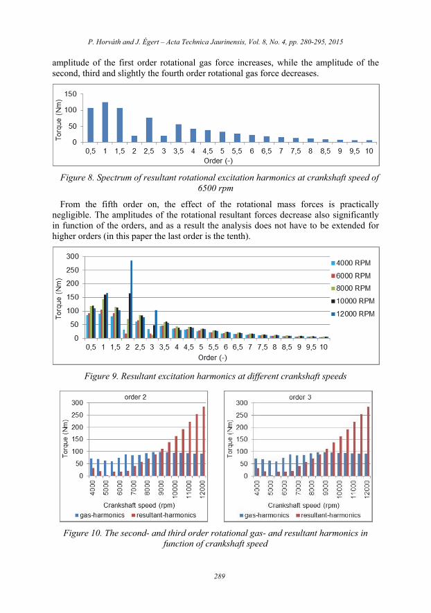
Figure 8. Spectrum of resultant rotational excitation harmonics at crankshaft speed of 6500 rpm
From the fifth order on, the effect of the rotational mass forces is practically negligible. The amplitudes of the rotational resultant forces decrease also significantly in function of the orders, and as a result the analysis does not have to be extended for higher orders (in this paper the last order is the tenth).
Figure 9. Resultant excitation harmonics at different crankshaft speeds
Figure 10. The second- and third order rotational gas- and resultant harmonics in function of crankshaft speed

P. Horváth and J. Égert – Acta Technica Jaurinensis, Vol. 8, No. 4, pp. 280-295, 2015
290
Studying the excitation harmonics in function of the crankshaft speed, it can be observed that – in case of any value of the crankshaft speed – the second and the third order rotational mass forces (Fig. 8.) have a major effect on the amplitude of the rotational gas force (Fig. 9.). Furthermore – as can be seen from Fig. 10. – in case of lower engine speeds, this effect means the decrease of the amplitude of the rotational gas force, while in case of higher engine speeds this effect means the increase of the same.
6. Defining critical speeds
Unlike the natural frequencies, the frequencies of the excitation harmonics ( e ) are
not constant, but they are increasing linearly in function of the crankshaft speed:
60e
nx , (12)
where n has to be substituted in rpm.
Plotting the excitation and natural frequencies in function of crankshaft speed, the excitation frequencies will be lines starting from the origin, while the natural frequencies will be horizontal lines. The critical speeds can be derived from the intersections of the excitation and natural frequency curves [11], [12].
According to Fig. 11. the first six excitation harmonics have no intersections even with the first natural frequency. Since the first six harmonics have the highest amplitudes – as can be seen from Fig. 9. – they are the most dangerous ones so avoiding them has an advantageous effect on the dynamic loading of the crankshaft. The first excitation harmonic that resonates with the first natural frequency is the 3,5th excitation harmonic. From Fig. 8. it can be seen that from this excitation harmonic on, the amplitudes of the harmonics decrease, so they generate smaller and smaller angular deflection. The examined first 20 excitation harmonics have 19 intersection points with the first and second natural frequencies, so that means that there are 19 critical speed values. Not every critical speed causes dangerous amplitudes, however.
Figure 11. Defining critical engine speeds

P. Horváth and J. Égert – Acta Technica Jaurinensis, Vol. 8, No. 4, pp. 280-295, 2015
291
On the one hand, the magnitude of the angular deflections depend on the amplitude of the excitation harmonic, on the other hand, the different damping effects in the system have a major decreasing effect on the magnitudes of the angular deflection. The next chapter deals with these magnitudes.
7. Damping of the crank mechanism
Since the system has a non-negligible damping, finite revolutions will occur at the resonance locations. Basically, there are two damping effects acting on the crank mechanism: damping of the piston.
damping of the valve control and different auxiliary equipment (like the oil pump or the water pump).
The damping effect of the piston - characterized by the damping coefficient dk -
acting on the crankpin (mass element 4J ) can be calculated with the following formula
according to [3]:
2
7 2 [ ]1,5 10 [ ]
4d
d
d mNmsk r m
rad
, (13)
where r is the throw of crank and dd is the diameter of the piston. The damping from
the effects of the valve control and auxiliary equipment was defined on the flywheel (mass element 1). The value of this can only be obtained through experiments. Without such experience one can only rely on the literature. Based on experiments measured by AVL [12] on similar one-cylinder engines, the value of this damping was considered as 1,2 /Nms rad
8. Solving the equations of motion in case of forced vibrations
Taking into consideration excitation and damping, the equation system of motion looks like the following formula [9]:
( )gM C K M t , (14)
where: M is the mass matrix, C is the damping matrix, K is the stiffness matrix,
( )gM t is the vector of the excitation forces / torques and t is the vector of angles of
revolution (unknown parameters).
The solution of this second order, ordinary, inhomogeneous differential equation system provides the forced angular deflection, the forced angular velocity and the forced angular acceleration of each mass element. Fig. 12. illustrates the angular deflection between the two ends of the crankshaft, between the flywheel (mass element 1) and the clutch (mass element 7). The angular deflection between the two ends of the crankshaft (15) is characteristic for the torsional stiffness of the crankshaft.
17 7 1 . (15)

P. Horváth and J. Égert – Acta Technica Jaurinensis, Vol. 8, No. 4, pp. 280-295, 2015
292
Figure 12. The angular deflection between the flywheel and the clutch in function of crank angle at 8000 rpm engine speed
In order to be able to plot the relative angular deflection of the crankshaft in function of the crankshaft speed, the mean relative angular deflection is calculated as follows:
17 max 17 min17 2
. (16)
Figure 13. Mean relative angular deflection of the two ends of the original crankshaft and that of the two ends of the modified crankshaft in function of engine speed
Fig. 13. shows the mean relative angular deflection of the crankshaft (16) in function of the crankshaft speed, while Fig. 14. shows the same quantity, but caused by the separate orders of the excitation forces. In order to be able to compare the results, the mean relative angular deflection of the original crankshaft [1] is also plotted in Fig. 13. According to Fig. 13. the maximal mean relative angular deflection of the modified crankshaft is approximately 30% higher compared to the original crankshaft. According to AVL design references [10], this value should be below 0,6○. As can be seen from Fig. 13. this criteria is fulfilled by both crankshafts.
As to the mean relative angular deflections caused by the separate orders of the excitation loads, AVL indicates a maximal value of 0,1○ in case of serial engines [10]. Above this limit value the engine noise increases. According to Fig. 14. this criteria is not fulfilled in case of orders below five, but since the examined crankshaft is from a race engine the engine noise is not an important issue.

P. Horváth and J. Égert – Acta Technica Jaurinensis, Vol. 8, No. 4, pp. 280-295, 2015
293
Figure 14. Mean relative angular deflection of the two ends of the modified crankshaft caused by the separate orders of the excitation force in function of engine speed
From Fig. 14. it can be observed, that the maximum values of angular deflection of the separate orders (the resonance locations) occur at critical speeds determined from Fig. 9. According to Fig. 9. in case of orders 3,5 – 7, the curve has one, while in case of orders 7,5 – 10, the curve has two maximum values. Furthermore, as excpected, the highest angular deflection occurs in case of order 3,5, while the maximum deflections decrease as the orders increase.
Besides the relative angular deflection, another characteristic quantity that is usually analysed is the speed irregularity of the clutch. In order to be able to calculate this, first the angular velocity of the clutch must be defined. This can be achieved by differentiating the angular deflection of the clutch (Fig. 15.).
Figure 15. Angular velocity of the clutch in function of crank-angle at 8000 rpm engine speed
The angular speed irregularity of the clutch is the difference between the maximum and the minimum angular speeds divided by the mean angular speed k :

P. Horváth and J. Égert – Acta Technica Jaurinensis, Vol. 8, No. 4, pp. 280-295, 2015
294
max min
k
, max min
2k
. (17)
The speed irregularity of the clutch of the original, as well as of the modified crankshaft [1] can be seen in Fig. 16.
Figure 16. The speed irregularity of the clutch of the original crankshaft (dashed line) and that of the modified crankshaft (continuous line) in function of engine speed
A too high value of speed irregularity has a negative effect on the fatigue life of the gearbox. In case of serial engines, the maximum acceptable value is approximately 0,16 –0,2. According to Fig. 16. the maximum value of the speed irregularity is approximately 0,18 in case of the original crankshaft, while in case of the modified crankshaft this value is slightly higher, approximately 0,19 at 4000 rpm engine speed. But this value rapidly decreases as the engine speed increases, at 5500 rpm engine speed it is already below 0,1 and it remains below this value in the largest part of the operational range.
9. Summary of the results
For the torsional dynamic analysis, we have created a sequential torsional multi-mass vibration model of the crankshaft mechanism. In order to be able to check the vibration characteristics of the torsional model, the first two natural frequencies and natural modes obtained from the multi-mass model were compared with those obtained from the 3D finite element model of the crankshaft. The error was below 2 % at the lowest two natural frequencies of the two different models. The natural modes have also shown a proper match and therefore the forced vibration analysis was performed only on the multi-mass model.
During the forced vibration analysis, the following statements could be made:
Up to the first ten excitation harmonics, two natural frequencies appear in the operational range of the engine, which result nineteen resonance locations altogether.
The first six excitation harmonics have no intersection with the natural frequencies. Since these harmonics have the highest amplitudes they are the most dangerous ones, avoiding them has an advantageous effect on the dynamic loading of the crankshaft.

P. Horváth and J. Égert – Acta Technica Jaurinensis, Vol. 8, No. 4, pp. 280-295, 2015
295
Also taking into account the dampings of the system, the mean relative angular deflection of the two ends of the modified crankshaft has increased by approximately 30 % compared to that of the two ends of the original crankshaft, so the result was a maximum value of 0,3○, which is still half of the limit-value of 0,6○ specified by AVL [10].
The speed irregularity of the clutch has slightly increased compared to the original crankshaft, the maximum value of 0,18 occuring in case of the original crankshaft has increased to approximately 0,19 at an engine speed of 4000 rpm. However this value rapidly decreases as the engine speed increases. At 5500 rpm engine speed this is already below 0,1 and it remains below this value in the largest part of the operational range.
References
[1] Horváth P, Égert J: Stress analysis and weight reduction of a one-cylinder engine crankshaft. Acta Technica Jaurinensis, Vol. 8, No. 3, pp. 201-217, 2015. DOI: 10.14513/actatechjaur.v8.n3.377
[2] AVL Excite Designer Primer (User’s Manual). AVL List Gmbh, Graz, 2009.
[3] AVL Excite Designer Theory. AVL List Gmbh, Graz, 2009.
[4] Parikyan T, Resch T, Priebsch HH: Structured model of crankshaft in the simulation of engine dynamics with AVL/Excite. AVL List Gmbh, Graz, 2001.
[5] ANSYS 14.5 Mechanical APDL Theory Reference. Ansys Inc., 2012.
[6] Mitianiec W, Buczek K: Torsional vibration analysis of a crankshaft in heavy duty six cylinder inline engine. Politechnika Krakowska Publisher, 2008.
[7] Meirelles PS, Zampieri DE, Mendes AS: Mathematical Model for Torsional Vibration Analysis in Internal Combustion Engines. 12th IFToMM World Congress, Besançon (France), June 18-21, 2007.
[8] Reynolds DD: Engineering principles of mechanical vibration (3rd edition). Trafford publishing, 2013.
[9] Osgood B: The Fourier Transform and its Applications. Stanford University, 2009.
[10] AVL Design References. AVL List Gmbh, Graz, Oral information.
[11] Corbo MA, Malanoski SB: Practical design against torsional vibration. In Proceedings of the Twenty-Fifth Turbomachinery Symposium, September, pp. 189-222, 1996.
[12] Huang Y, Yang S, Zhang F, Zhao C, Ling Q, Wang H: Nonlinear Torsional Vibration Characteristics of an Internal Combustion Engine Crankshaft Assembly. Chinese Journal of Mechanical Engineering, Vol. 25, Issue 4, pp. 797-808, July 2012.


![Cooperatorum Veritatis Societas Excerpta ex Documenta ...documentacatholicaomnia.eu/02g/0345-0399,_Evagrius_Ponticus,_De... · [00029] ∆ειλὸς στρατιώτης φρίσσει](https://img.dokumen.tips/doc/110x75/5a8244ed7f8b9a38478de8e7/cooperatorum-veritatis-societas-excerpta-ex-documenta-doc-evagriusponticusde00029.jpg)