Embed Size (px)
Citation preview
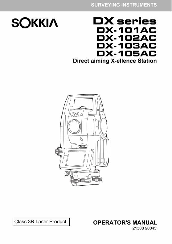
SURVEYING INSTRUMENTS
Class 3R Laser Product OPERATOR'S MANUAL
DX seriesDX-101ACDX-102ACDX-103ACDX-105AC
Direct aiming X-ellence Station
21308 90045
HOW TO READ THIS MANUAL
Thank you for selecting the DX-101AC/102AC/103AC/105AC.• Please read this Operator’s manual carefully, before using this product.• DX has a function to output data to a connected host computer. Command operations from a host
computer can also be performed. For details, refer to "Communication manual" and ask your local dealer.
• The specifications and general appearance of the instrument are subject to change without prior notice and without obligation by TOPCON CORPORATION and may differ from those appearing in this manual.
• The content of this manual is subject to change without notice.• Some of the diagrams shown in this manual may be simplified for easier understanding.• This manual is protected by copyright and all rights are reserved by TOPCON CORPORATION.• Except as permitted by Copyright law, this manual may not be copied, and no part of this manual
may be reproduced in any form or by any means. • This manual may not be modified, adapted or otherwise used for the production of derivative works.
Symbols
The following conventions are used in this manual.
: Indicates precautions and important items which should be read before operations.
: Indicates the chapter title to refer to for additional information.
: Indicates supplementary explanation.
: Indicates an explanation for a particular term or operation.
[Softkey] etc. : Indicates softkeys on the display and window dialog buttons.
{Key} etc. : Indicates keys on the operation panel.
<Screen title> etc. : Indicates screen titles.
i
Notes regarding manual style
• Except where stated, “DX” means DX-101AC/102AC/103AC/105AC in this manual.• Face 2 display is available as standard or as a factory option depending on the country of purchase.• Location of softkeys in screens used in procedures is based on the factory setting. It is possible to
change the allocation of softkeys.Softkey allocation: "19.6 Allocating Key Functions"
• Learn basic operations in "4. PRODUCT OUTLINE" and "5. BASIC OPERATION" before you read each measurement procedure. For selecting options and inputting figures, see "5.1 Basic Key Operation".
• Measurement procedures are based on continuous measurement. Some information about procedures when other measurement options are selected can be found in “Note” ( ).
• KODAK is a registered trademark of Eastman Kodak Company.• Bluetooth® is a registered trademark of Bluetooth SIG, Inc.• Windows and Windows CE are registered trademarks of Microsoft Corporation.• All other company and product names featured in this manual are trademarks or registered
trademarks of each respective organization.
Li-ion S Li-ion
This is the mark of the Japan Surveying Instruments Manufacturers Association.
ii
CONTENTS
1. PRECAUTIONS FOR SAFE OPERATION............................ 12. PRECAUTIONS ..................................................................... 43. LASER SAFETY INFORMATION .......................................... 84. PRODUCT OUTLINE........................................................... 104.1 Parts of the Instrument .................................................................. 104.2 Mode Structure .............................................................................. 154.3 Bluetooth Wireless Technology ..................................................... 16
5. BASIC OPERATION ............................................................ 185.1 Basic Key Operation ...................................................................... 185.2 Display Functions .......................................................................... 225.3 Inputting Characters using the Input Panel ................................... 265.4 Starkey Mode ................................................................................ 275.5 Using the Program Selection Screen ............................................ 32
6. USING THE BATTERY........................................................ 336.1 Battery Charging ........................................................................... 336.2 Installing/Removing the Battery ..................................................... 34
7. SETTING UP THE INSTRUMENT....................................... 367.1 Centering ....................................................................................... 367.2 Levelling ........................................................................................ 38
8. POWER ON/OFF................................................................. 408.1 Resolving Software Issues ............................................................ 418.2 Configuring the Touch Panel ......................................................... 418.3 Powering ON/OFF from an External Instrument ........................... 42
9. CONNECTING TO EXTERNAL DEVICES .......................... 439.1 Wireless Communication using Bluetooth Technology ................. 439.2 Communication between the DX and Companion Device ............ 479.3 Connection via RS232C Cable ...................................................... 489.4 Connecting via USB Cable ............................................................ 499.5 Inserting USB Memory .................................................................. 52
10. TARGET SIGHTING ............................................................ 5310.1 Auto Pointing Settings ................................................................... 5410.2 Auto-Pointing Function for Target Sighting ................................... 5610.3 Manually Sighting the Target ......................................................... 57
11. ANGLE MEASUREMENT.................................................... 5911.1 Measuring the Horizontal Angle between Two Points
iii
CONTENTS
(Horizontal Angle 0°) ..................................................................... 5911.2 Setting the Horizontal Angle to a Required Value (Horizontal Angle Hold) ................................................................. 60
11.3 Turning the Instrument from the Reference Angle to a Specified Angle .......................................................................... 61
11.4 Angle measurement and Outputting the Data ............................... 62
12. DISTANCE MEASUREMENT.............................................. 6312.1 Returned Signal Checking ............................................................. 6312.2 Using the Guide Light in Distance Measurement .......................... 6512.3 Distance and Angle Measurement ................................................ 6612.4 Distance Measurement and Outputting the Data .......................... 6712.5 REM Measurement ....................................................................... 68
13. COORDINATE MEASUREMENT ........................................ 7013.1 Entering Instrument Station Data .................................................. 7013.2 Azimuth Angle Setting ................................................................... 7113.3 3-D Coordinate Measurement ....................................................... 74
14. RESECTION MEASUREMENT ........................................... 7614.1 Coordinate Resection Measurement ............................................. 7714.2 Height Resection Measurement .................................................... 81
15. SETTING-OUT MEASUREMENT........................................ 8615.1 Using the Guide Light in Setting-out Measurement ....................... 8615.2 Distance Setting-out Measurement ............................................... 8715.3 Coordinates Setting-out Measurement .......................................... 9115.4 REM Setting-out Measurement ..................................................... 95
16. OFFSET MEASUREMENT.................................................. 9716.1 Offset Single-distance Measurement ............................................ 9716.2 Offset Angle Measurement ............................................................ 9916.3 Offset Two-distance Measurement ............................................. 101
17. MISSING LINE MEASUREMENT...................................... 10417.1 Measuring the Distance between 2 or more Points ..................... 10417.2 Changing the Starting Point ........................................................ 106
18. SURFACE AREA CALCULATION..................................... 10819. CHANGING THE SETTINGS ............................................ 112
19.1 Observation Conditions ............................................................... 11219.2 Instrument Configuration ............................................................. 11519.3 EDM Settings .............................................................................. 117
iv
CONTENTS
19.4 Allocating User-defined Tabs ...................................................... 12119.5 Customizing Screen Controls ...................................................... 12419.6 Allocating Key Functions ............................................................. 12619.7 Changing Starkey Mode Icons .................................................... 12919.8 Units ............................................................................................ 13119.9 Changing Password .................................................................... 13219.10 Restoring Default Settings ........................................................... 13319.11 Date and Time ............................................................................. 13320. WARNING AND ERROR MESSAGES.............................. 13421. CHECKS AND ADJUSTMENTS........................................ 137
21.1 Circular Level .............................................................................. 13721.2 Tilt Sensor ................................................................................... 13821.3 Collimation ................................................................................... 14121.4 Reticle ......................................................................................... 14221.5 Image Sensor Reticle .................................................................. 14421.6 Optical Plummet .......................................................................... 14621.7 Additive Distance Constant ......................................................... 14721.8 Laser Plummet (Option) .............................................................. 148
22. POWER SUPPLY SYSTEM .............................................. 15123. TARGET SYSTEM............................................................. 15224. OPPTIONAL ACCESSORIES ........................................... 15525. SPECIFICATIONS ............................................................. 15726. EXPLANATIONS .............................................................. 164
26.1 High Accuracy with the 360° Prism ............................................. 16426.2 Manually Indexing the Vertical Circle by Face Left,
Face Right Measurement ............................................................ 165
27. REGULATIONS ................................................................. 16628. INDEX ................................................................................ 170
v
1. PRECAUTIONS FOR SAFE OPERATION
For the safe use of the product and prevention of injury to operators and other persons as well as prevention of property damage, items which should be observed are indicated by an exclamation point within a triangle used with WARNING and CAUTION statements in this operator’s manual.The definitions of the indications are listed below. Be sure you understand them before reading the manual’s main text.Definition of Indication
General
WARNING Ignoring this indication and making an operation error could possibly result in death or serious injury to the operator.
CAUTION Ignoring this indication and making an operation error could possibly result in personal injury or property damage.
This symbol indicates items for which caution (hazard warnings inclusive) is urged. Specific details are printed in or near the symbol.
This symbol indicates items which are prohibited. Specific details are printed in or near the symbol.
This symbol indicates items which must always be performed. Specific details are printed in or near the symbol.
Warning
Do not use the unit in areas exposed to high amounts of dust or ash, in areas where there is inadequate ventilation, or near combustible materials. An explosion could occur.
Do not perform disassembly or rebuilding. Fire, electric shock, burns, or hazardous radiation exposure could result.
Never look at the sun through the telescope. Loss of eyesight could result.
Do not look at reflected sunlight from a prism or other reflecting object through the telescope. Loss of eyesight could result.
Direct viewing of the sun using the telescope during sun observation will cause loss of eyesight. Use a solar filter (option) for sun observation.
When securing the instrument in the carrying case make sure that all catches, including the side catches, are closed. Failure to do so could result in the instrument falling out while being carried, causing injury.
Caution
Do not use the carrying case as a footstool. The case is slippery and unstable so a person could slip and fall off it.
1
1. PRECAUTIONS FOR SAFE OPERATION
Power Supply
Do not place the instrument in a case with a damaged catch, belt or handle. The case or instrument could be dropped and cause injury.
Do not touch the instrument or look through the telescope while the motor is in operation. Injury could result.
Do not wield or throw the plumb bob. A person could be injured if struck.
Secure handle to main unit with handle locks. Failure to properly secure the handle could result in the unit falling off while being carried, causing injury.
Tighten the adjustment tribrach clamp securely. Failure to properly secure the clamp could result in the tribrach falling off while being carried, causing injury.
Warning
Do not short circuit. Heat or ignition could result.
Do not place articles such as clothing on the battery charger while charging batteries. Sparks could be induced, leading to fire.
Do not use voltage other than the specified power supply voltage. Fire or electrical shock could result.
Do not use batteries other than those designated. An explosion could occur, or abnormal heat generated, leading to fire.
Do not use damaged power cords, plugs or loose outlets. Fire or electric shock could result.
Do not use power cords other than those designated. Fire could result.
Use only the specified battery charger to recharge batteries. Other chargers may be of different voltage rating or polarity, causing sparking which could lead to fire or burns.
Do not use the battery or charger for any other equipment or purpose. Fire or burns caused by ignition could result.
Do not heat or throw batteries or chargers into fire. An explosion could occur, resulting in injury.
To prevent shorting of the battery in storage, apply insulating tape or equivalent to the terminals. Otherwise shorting could occur resulting in fire or burns.
Do not use batteries or the battery charger if wet. Resultant shorting could lead to fire or burns.
Do not connect or disconnect power supply plugs with wet hands. Electric shock could result.
2
1. PRECAUTIONS FOR SAFE OPERATION
Tripod
Bluetooth wireless technology
Caution
Do not touch liquid leaking from batteries. Harmful chemicals could cause burns or blisters.
Caution
When mounting the instrument to the tripod, tighten the centering screw securely. Failure to tighten the screw properly could result in the instrument falling off the tripod, causing injury.
Tighten securely the leg fixing screws of the tripod on which the instrument is mounted. Failure to tighten the screws could result in the tripod collapsing, causing injury.
Do not carry the tripod with the tripod shoes pointed at other persons. A person could be injured if struck by the tripod shoes.
Keep hands and feet away from the tripod shoes when fixing the tripod in the ground. A hand or foot stab wound could result.
Tighten the leg fixing screws securely before carrying the tripod. Failure to tighten the screws could lead to the tripod legs extending, causing injury.
Warning
Do not use within the vicinity of hospitals. Malfunction of medical equipment could result.
Use the instrument at a distance of at least 22 cm from anyone with a cardiac pacemaker. Otherwise, the pacemaker may be adversely affected by the electromagnetic waves produced and cease to operate as normal.
Do not use onboard aircraft. The aircraft instrumentation may malfunction as a result.
Do not use within the vicinity of automatic doors, fire alarms and other devices with automatic controls as the electromagnetic waves produced may adversely affect operation resulting in an accident.
3
2. PRECAUTIONS
Charging Battery• Be sure to charge the battery within the charging temperature range.Charging temperature range: 0 to 40°C
Warranty policy for Battery
• Battery is an expendable item. The decline in retained capacity depending on the repeated charging/discharging cycle is out of warranty.
Bluetooth Wireless Technology
• Bluetooth function may not be built in depending on telecommunications regulations of the country or the area where the instrument is purchased. Contact your local dealer for the details.
Telescope
• Aiming the telescope at the sun will cause internal damage to the instrument. Use the solar filter when observing the sun.
"24. OPPTIONAL ACCESSORIES"
Tribrach Clamp and Handle
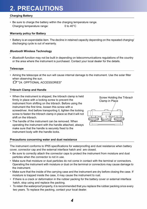
• When the instrument is shipped, the tribrach clamp is held firmly in place with a locking screw to prevent the instrument from shifting on the tribrach. Before using the instrument the first time, loosen this screw with a screwdriver. And before transporting it, tighten the locking screw to fasten the tribrach clamp in place so that it will not shift on the tribrach.
• The handle of the instrument can be removed. When operating the instrument with the handle attached, always make sure that the handle is securely fixed to the instrument body with the handle locks.
Precautions concerning water and dust resistance
The instrument conforms to IP65 specifications for waterproofing and dust resistance when battery cover, connector cap and the external interface hatch and are closed.• Be sure to correctly attach the connector caps to protect the instrument from moisture and dust
particles when the connector is not in use.• Make sure that moisture or dust particles do not come in contact with the terminal or connectors.
Operating the instrument with moisture or dust on the terminal or connectors may cause damage to the instrument.
• Make sure that the inside of the carrying case and the instrument are dry before closing the case. If moisture is trapped inside the case, it may cause the instrument to rust.
• If there is a crack or deformation in the rubber packing for the battery cover or external interface hatch, stop using and replace the packing.
• To retain the waterproof property, it is recommended that you replace the rubber packing once every two years. To replace the packing, contact your local dealer.
4
2. PRECAUTIONS
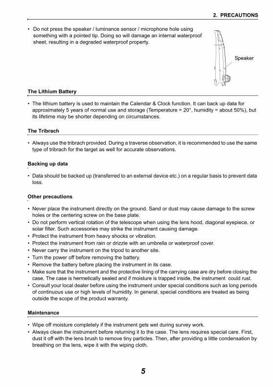
• Do not press the speaker / luminance sensor / microphone hole using something with a pointed tip. Doing so will damage an internal waterproof sheet, resulting in a degraded waterproof property.
The Lithium Battery
• The lithium battery is used to maintain the Calendar & Clock function. It can back up data for approximately 5 years of normal use and storage (Temperature = 20°, humidity = about 50%), but its lifetime may be shorter depending on circumstances.
The Tribrach
• Always use the tribrach provided. During a traverse observation, it is recommended to use the same type of tribrach for the target as well for accurate observations.
Backing up data
• Data should be backed up (transferred to an external device etc.) on a regular basis to prevent data loss.
Other precautions
• Never place the instrument directly on the ground. Sand or dust may cause damage to the screw holes or the centering screw on the base plate.
• Do not perform vertical rotation of the telescope when using the lens hood, diagonal eyepiece, or solar filter. Such accessories may strike the instrument causing damage.
• Protect the instrument from heavy shocks or vibration.• Protect the instrument from rain or drizzle with an umbrella or waterproof cover.• Never carry the instrument on the tripod to another site.• Turn the power off before removing the battery.• Remove the battery before placing the instrument in its case.• Make sure that the instrument and the protective lining of the carrying case are dry before closing the
case. The case is hermetically sealed and if moisture is trapped inside, the instrument could rust.• Consult your local dealer before using the instrument under special conditions such as long periods
of continuous use or high levels of humidity. In general, special conditions are treated as being outside the scope of the product warranty.
Maintenance
• Wipe off moisture completely if the instrument gets wet during survey work.• Always clean the instrument before returning it to the case. The lens requires special care. First,
dust it off with the lens brush to remove tiny particles. Then, after providing a little condensation by breathing on the lens, wipe it with the wiping cloth.
Speaker
5
2. PRECAUTIONS
• If the display is dirty, carefully wipe it with a soft, dry cloth. To clean other parts of the instrument or the carrying case, lightly moisten a soft cloth in a mild detergent solution. Wring out excess water until the cloth is slightly damp, then carefully wipe the surface of the unit. Do not use any alkaline cleaning solutions, alcohol, or any other organic solvents on the instrument or display.
For temporal de-activating the touch panel, see "5.2 Display Functions", "19. CHANGING THE SETTINGS"
• Store the instrument in a dry room where the temperature remains fairly constant.• Check the tripod for loose fit and loose screws.• If any trouble is found on the rotatable portion, screws or optical parts (e.g. lens), contact your local
dealer.• When the instrument is not used for a long time, check it at least once every 3 months.
"21. CHECKS AND ADJUSTMENTS"• Every 4,000 to 5,000 hours operation in total, change grease of driving parts. Contact your local
dealer for the maintenance.• When removing the instrument from the carrying case, never pull it out by force. The empty carrying
case should be closed to protect it from moisture.• Check the instrument for proper adjustment periodically to maintain the instrument accuracy.
Exporting this product (Relating EAR)
• This product is equipped with the parts/units, and contains software/technology, which are subject to the EAR (Export Administration Regulations). Depending on countries you wish to export or bring the product to, a US export license may be required. In such a case, it is your responsibility to obtain the license. The countries requiring the license as of May 2013 are shown below. Please consult the Export Administration Regulations as they are subject to change.
North KoreaIranSyriaSudanCuba
URL for the EAR of the US: http://www.bis.doc.gov/policiesandregulations/ear/index.htm
Exporting this product (Relating telecommunications regulations)
• Wireless communication module is incorporated in the instrument. Use of this technology must be compliant with telecommunications regulations of the country where the instrument is being used. Even exporting the wireless communication module may require conformity with the regulations. Contact your local dealer in advance.
6
2. PRECAUTIONS
Exceptions from responsibility
• The user of this product is expected to follow all operating instructions and make periodic checks (hardware only) of the product’s performance.
• The manufacturer, or its representatives, assumes no responsibility for results of faulty or intentional usage or misuse including any direct, indirect, consequential damage, or loss of profits.
• The manufacturer, or its representatives, assumes no responsibility for consequential damage, or loss of profits due to any natural disaster, (earthquake, storms, floods etc.), fire, accident, or an act of a third party and/or usage under unusual conditions.
• The manufacturer, or its representatives, assumes no responsibility for any damage (change of data, loss of data, loss of profits, an interruption of business etc.) caused by use of the product or an unusable product.
• The manufacturer, or its representatives, assumes no responsibility for any damage, and loss of profits caused by usage different to that explained in the operator’s manual.
• The manufacturer, or its representatives, assumes no responsibility for damage caused by incorrect operation, or action resulting from connecting to other products.
7
3. LASER SAFETY INFORMATION
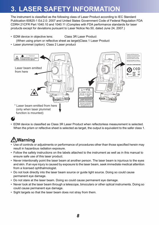
The instrument is classified as the following class of Laser Product according to IEC Standard Publication 60825-1 Ed.2.0: 2007 and United States Government Code of Federal Regulation FDA CDRH 21CFR Part 1040.10 and 1040.11 (Complies with FDA performance standards for laser products except for deviations pursuant to Laser Notice No.50, dated June 24, 2007.)• EDM device in objective lens: Class 3R Laser Product(When using prism or reflective sheet as target)Class 1 Laser Product
• Laser plummet (option): Class 2 Laser product
• EDM device is classified as Class 3R Laser Product when reflectorless measurement is selected. When the prism or reflective sheet is selected as target, the output is equivalent to the safer class 1.
Warning• Use of controls or adjustments or performance of procedures other than those specified herein may
result in hazardous radiation exposure.• Follow the safety instructions on the labels attached to the instrument as well as in this manual to
ensure safe use of this laser product.• Never intentionally point the laser beam at another person. The laser beam is injurious to the eyes
and skin. If an eye injury is caused by exposure to the laser beam, seek immediate medical attention from a licensed ophthalmologist.
• Do not look directly into the laser beam source or guide light source. Doing so could cause permanent eye damage.
• Do not stare at the laser beam. Doing so could cause permanent eye damage.• Never look at the laser beam through a telescope, binoculars or other optical instruments. Doing so
could cause permanent eye damage.• Sight targets so that the laser beam does not stray from them.
AVOID EXPOSURE-Laser radiationis emitted from this aperture.
LASER RADIATIONAVOID DIRECT EYE EXPOSURE
MAX 5mW LD 625-695nmCLASS3R LASER PRODUCT
IEC 60825-1 Ed. 2.0 : 2007* Laser beam emitted from here (only when laser plummet function is mounted)
Laser beam emittedfrom here
*
8
3. LASER SAFETY INFORMATION
Caution• Perform checks at start of work and periodic checks and adjustments with the laser beam emitted
under normal conditions. • When the instrument is not being used, turn off the power and replace the lens cap.• When disposing of the instrument, destroy the battery connector so that the laser beam cannot be
emitted.• Operate the instrument with due caution to avoid injuries that may be caused by the laser beam
unintentionally striking a person in the eye. Avoid setting the instrument at heights at which the path of the laser beam may strike pedestrians or drivers at head height.
• Never point the laser beam at mirrors, windows or surfaces that are highly reflective. The reflected laser beam could cause serious injury.
• Only those who have been received training as per the following items shall use this product. • Read this manual for usage procedures for this product.• Hazardous protection procedures (read this chapter).• Requisite protective gear (read this chapter).• Accident reporting procedures (stipulate procedures beforehand for transporting the injured and
contacting physicians in case there are laser induced injuries).• Persons working within the range of the laser beam are advised to wear eye protection which
corresponds to the laser wavelength of the instrument being used• Areas in which the laser is used should be posted with a standard laser warning sign. • When using the laser-pointer function, be sure to turn OFF the output laser after distance
measurement is completed. Even if distance measurement is canceled, the laser-pointer function is still operating and the laser beam continues to be emitted.
9
4. PRODUCT OUTLINE
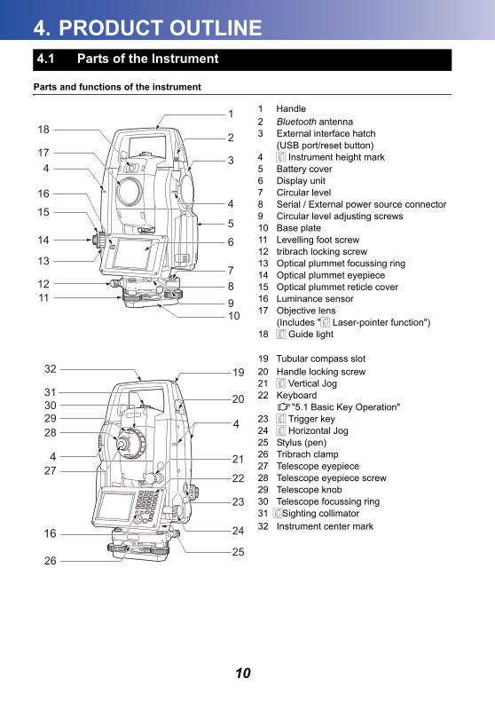
Parts and functions of the instrument
1 Handle2 Bluetooth antenna3 External interface hatch
(USB port/reset button)4 Instrument height mark5 Battery cover6 Display unit7 Circular level8 Serial / External power source connector9 Circular level adjusting screws10 Base plate11 Levelling foot screw12 tribrach locking screw13 Optical plummet focussing ring14 Optical plummet eyepiece15 Optical plummet reticle cover16 Luminance sensor17 Objective lens
(Includes " Laser-pointer function")18 Guide light
19 Tubular compass slot20 Handle locking screw21 Vertical Jog22 Keyboard
"5.1 Basic Key Operation"23 Trigger key24 Horizontal Jog25 Stylus (pen)26 Tribrach clamp27 Telescope eyepiece28 Telescope eyepiece screw29 Telescope knob30 Telescope focussing ring31 Sighting collimator32 Instrument center mark
4.1 Parts of the Instrument
4
417
181
2
3
7
6
5
98
10
1112
14
13
16
15
19
20
23
21
22
24
25
28
27
26
293031
32
4
4
16
10

4. PRODUCT OUTLINE
Instrument height markThe height of the instrument is as follows:• 196mm (from tribrach mounting surface to this mark)"Instrument height" is input when setting instrument station data and is the height from the surveying point (where the instrument is mounted) to this mark.
Laser-pointer functionA target can be sighted with a red laser beam in dark locations without the use of the telescope.
Guide light Setting-out measurement etc. can be carried out effectively using the guide light. The guide light is composed of a light that is divided into green and red sections. A poleman can ascertain the present position by checking the guide light color.
Guide light status
"12.2 Using the Guide Light in Distance Measurement", "15.1 Using the Guide Light in Setting-out Measurement"
Light status MeaningSlow flashing (Red and green simultaneously)
Waiting
Fast flashing (Red and green simultaneously)
Searching in progressMeasuring (continuous measurement)Returned signal checking in progress
Green and red alternate flashing
Distance measurement error (no signal, sighting error)Search error (error screen only)
green red
Guide light
(When seen from the objective lens side while the instrument is in the Face 1 state)
11
4. PRODUCT OUTLINE
Vertical and Horizontal JogsThe instrument and telescope can be rotated manually by hand or, for more precise adjustments, by turning the vertical and horizontal Jogs.The faster the Jogs are turned, the faster the instrument and telescope rotate.
"10.1 Auto Pointing Settings" step 3
Trigger keyWhen the Trigger key is pressed the instrument carries out the operation indicated by the softkey in bold type on the screen. This allows the user to continue operation without having to return to the display to press softkeys.
Sighting collimatorUse sighting collimator to aim the instrument in the direction of the measurement point.Turn the instrument until the apex of the triangle in the sighting collimator is aligned with the target. A circle surrounds the triangle to make it easier to locate.
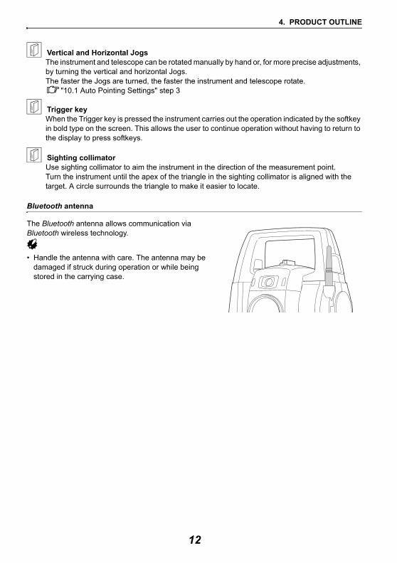
Bluetooth antenna
The Bluetooth antenna allows communication via Bluetooth wireless technology.
• Handle the antenna with care. The antenna may be damaged if struck during operation or while being stored in the carrying case.
12
4. PRODUCT OUTLINE
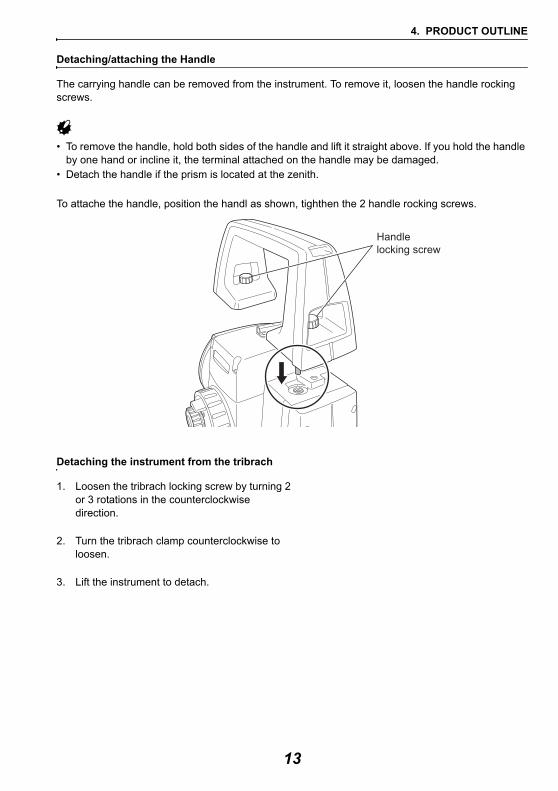
Detaching/attaching the Handle
The carrying handle can be removed from the instrument. To remove it, loosen the handle rocking screws.
• To remove the handle, hold both sides of the handle and lift it straight above. If you hold the handle by one hand or incline it, the terminal attached on the handle may be damaged.
• Detach the handle if the prism is located at the zenith.
To attache the handle, position the handl as shown, tighthen the 2 handle rocking screws.
Detaching the instrument from the tribrach
1. Loosen the tribrach locking screw by turning 2 or 3 rotations in the counterclockwise direction.
2. Turn the tribrach clamp counterclockwise to loosen.
3. Lift the instrument to detach.
Handlelocking screw
13
4. PRODUCT OUTLINE
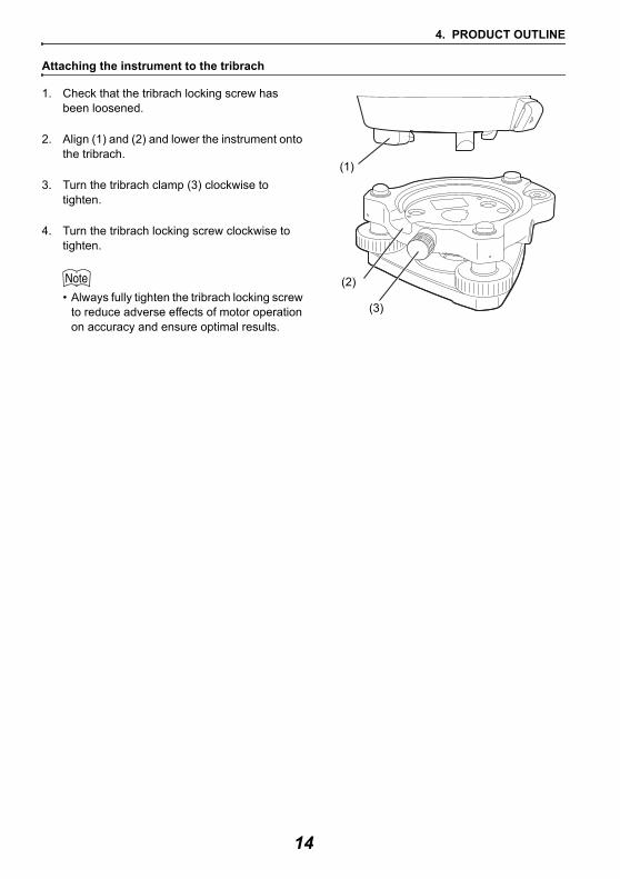
Attaching the instrument to the tribrach
1. Check that the tribrach locking screw has been loosened.
2. Align (1) and (2) and lower the instrument onto the tribrach.
3. Turn the tribrach clamp (3) clockwise to tighten.
4. Turn the tribrach locking screw clockwise to tighten.
• Always fully tighten the tribrach locking screw to reduce adverse effects of motor operation on accuracy and ensure optimal results.
(1)
(2)
(3)
14
4. PRODUCT OUTLINE
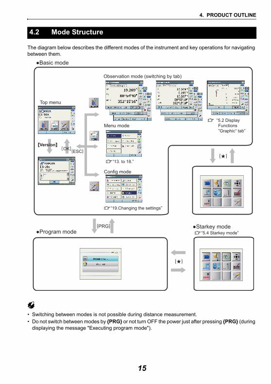
The diagram below describes the different modes of the instrument and key operations for navigating between them.
• Switching between modes is not possible during distance measurement.• Do not switch between modes by {PRG} or not turn OFF the power just after pressing {PRG} (during
displaying the message "Executing program mode").
4.2 Mode Structure
●Program mode●Starkey mode
Top menu
Observation mode (switching by tab)
Menu mode
Config mode
��“5.2 Display Functions
”Graphic“ tab”
VersionOK
●Basic mode
�“5.4 Starkey mode”PRG
ESC
�“19.Changing the settings”
�“13. to 18.”
15
4. PRODUCT OUTLINE
• Bluetooth function may not be built in depending on telecommunications regulations of the country or the area where the instrument is purchased. Contact your local dealer for the details.
• Use of this technology must be authorized according to telecommunications regulations of the country where the instrument is being used. Contact your local dealer in advance.
"27. REGULATIONS" • TOPCON CORPORATION is not liable for the content of any transmission nor any content related
thereto. When communicating important data, run tests beforehand to ascertain that communication is operating normally.
• Do not divulge the content of any transmission to any third party.
Radio interference when using Bluetooth technology
Bluetooth communication with the DX uses the 2.4 GHz frequency band. This is the same band used by the devices described below.
•Industrial, scientific, and medical (ISM) equipment such as microwaves and pacemakers.• portable premises radio equipment (license required) used in factory production lines etc.• portable specified low-power radio equipment (license-exempt) •IEEE802.11b/IEEE802.11g standard wireless LAN devices
The above devices use the same frequency band as Bluetooth communications. As a result, using the DX within proximity to the above devices may result in interference causing communication failure or reduction of transmission speed.
Although a radio station license is not required for this instrument, bear in mind the following points when using Bluetooth technology for communication.
Regarding portable premises radio equipment and portable specified low-power radio equipment: • Before starting transmission, check that operation will not take place within the vicinity of
portable premises radio equipment or specified low-power radio equipment.• In the case that the instrument causes radio interference with portable premises radio
equipment, terminate the connection immediately and take measures to prevent further interference (e.g. connect using an interface cable).
• In the case that the instrument causes radio interference with portable specified low-power radio equipment, contact your local dealer.
When using the DX in proximity to IEEE802.11b or IEEE802.11g standard wireless LAN devices, turn off all devices not being used.• Interference may result, causing transmission speed to slow or even disrupting the connection
completely. Turn off all devices not being used.
Do not use the DX in proximity to microwaves.• Microwave ovens can cause significant interference resulting in communication failure. Perform
communication at a distance of 3m or more from microwave ovens.
4.3 Bluetooth Wireless Technology
16
4. PRODUCT OUTLINE
Refrain from using the DX in proximity to televisions and radios.• Televisions and radios use a different frequency band to Bluetooth communications.
However, even if the DX is used within proximity to the above equipment with no adverse effects with regard to Bluetooth communication, moving a Bluetooth compatible device (including the DX) closer to said equipment may result in electronic noise in sound or images, adversely affecting the performance of televisions and radios.
Precautions regarding transmission
For best results• The usable range becomes shorter when obstacles block the line of sight, or devices such as
PDAs or computers are used. Wood, glass and plastic will not impede communication but the usable range becomes shorter. Moreover, wood, glass and plastic containing metal frames, plates, foil and other heat shielding elements as well as coatings containing metallic powders may adversely affect Bluetooth communication and concrete, reinforced concrete, and metal will render it impossible.
• Use a vinyl or plastic cover to protect the instrument from rain and moisture. Metallic materials should not be used.
• The direction of the Bluetooth antenna can have adverse effects upon usable range.
Reduced range due to atmospheric conditions• The radio waves used by the DX may be absorbed or scattered by rain, fog, and moisture from
the human body with the limit of usable range becoming lower as a result. Similarly, usable range may also shorten when performing communication in wooded areas. Moreover, as wireless devices lose signal strength when close to the ground, perform communication at as high a position as possible.
• TOPCON CORPORATION cannot guarantee full compatibility with all Bluetooth products on the market.
17
5. BASIC OPERATION
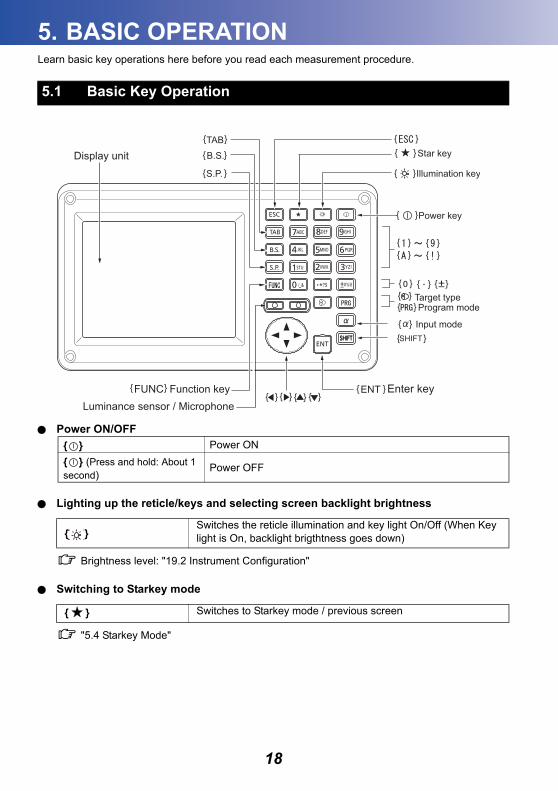
Learn basic key operations here before you read each measurement procedure.Power ON/OFF
Lighting up the reticle/keys and selecting screen backlight brightness
Brightness level: "19.2 Instrument Configuration"
Switching to Starkey mode
"5.4 Starkey Mode"
5.1 Basic Key Operation
{ } Power ON{ } (Press and hold: About 1 second)
Power OFF
{ }Switches the reticle illumination and key light On/Off (When Key light is On, backlight brigthtness goes down)
{ ★ } Switches to Starkey mode / previous screen
SHIFT
Display unit
Luminance sensor / Microphone
Target typeProgram mode
Function key
Input modeSHIFT
Illumination key
FUNC
{ }
{ }
{ }
{ }{ }
{ }
{ }
{ } { }{ } { }
{ }
{ } { } { }{ }{ }
{ }
{ }{ }
18
5. BASIC OPERATION
Switching to Program mode
• Do not switch between modes by {PRG} or not turn OFF the power just after pressing {PRG} (during displaying the message "Executing program mode").
Switching target type
"19.3 EDM Settings"
• Changes can also be made by tapping the icon on status bar or in Starkey mode."5.2 Display Functions", "5.4 Starkey Mode"
Switching the Laser-pointer/Guide light ON/OFF
• Changes can also be made by tapping the icon on status bar or in Starkey mode."5.2 Display Functions", "5.4 Starkey Mode"
Switching the page
Inputting letters/figures
{PRG} Switches to program mode / basic mode
{ }Switches between target typesPrism/360° Prism/Sheet/N-prism (reflectorless)
{ } (Press and hold until a beep sounds)
Turn ON/OFF the laser-pointer/guide light
{FUNC} Toggle between Observation mode screen pages
{α} Switch between numerals and alphabetic characters
{SHIFT} + {1} to {9} In alphabetic characters mode, switch between lowercase characters and upper case characters each time
{SHIFT} (Press and hold) In alphabetic characters mode, switch between lowercase characters and upper case characters
{SHIFT} + {α} Display/hide <Input Panel>
{0} to {9}
Input numeral or symbol printed above the key (during numeric input mode)Input alphabetic character in the order they are listed (in alphabetic input mode)
{.} Input a decimal point (during numeric input mode)Input code (in alphabetic input mode)
{±} Input a plus or minus sign (during numeric input mode)Input code (in alphabetic input mode)
19
5. BASIC OPERATION
Inputting rule and inputting special characters: "5.3 Inputting Characters using the Input Panel"
Selecting options
Selecting tabs
Tabs: "5.2 Display Functions"
Others
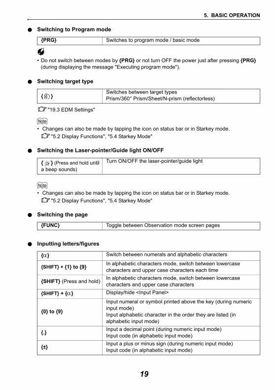
Example: Entering "computer" (lower case) as the name of a new device
1. Tap the input mode icon in the status bar (second from bottom) until "_a" is displayed.
{ESC} Cancel the input data{TAB} Shift to the next item{B.S.} Delete a character on the left.
{S.P.} Input a blank space (increments by 1 when setting the date and time)
{ }/{ } Move the cursor left/right{ }/{ } Move the cursor up/down{ENT} Select/accept input word/value
{ }/{ } Move the cursor/selection item up/down{ }/{ } Move the cursor/selection item left/right or select other option{TAB} Shift to the next item{S.P.} Display other options{ENT} Select/accept the option
{ }/{ } Move tab/cursor in tab up/down{ }/{ } Display next tab at left/right
{ESC} Return to previous screen
20
5. BASIC OPERATION
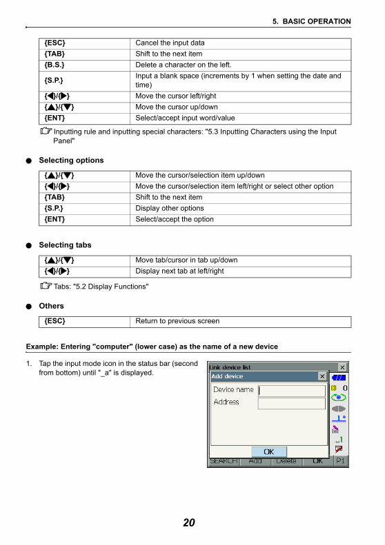
2. Press {7} three times."c" is displayed.
3. Press {5} three times."o" is displayed.
4. Press { }. Press {5}. "m" is displayed.
5. Continue to input letters. Press {ENT} to complete inputting.
P1
21
5. BASIC OPERATION
Screens can be selected/operated using the keys on the keyboard or the touch panel. The touch panel can be operated using either the stylus pen provided or your fingers.It is also possible to de-activate the touch panel temporarily.
"19. CHANGING THE SETTINGS"
• Do not scratch the display or use any sharp implement other than the stylus pen to operate the touch panel.
Using the stylus
The stylus pen can be used to select menus and buttons on the screen and operate the scroll bar.
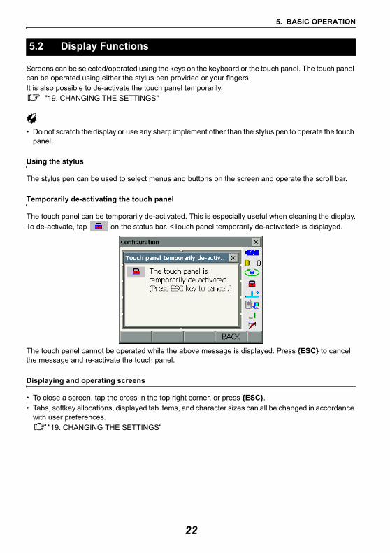
Temporarily de-activating the touch panel
The touch panel can be temporarily de-activated. This is especially useful when cleaning the display.To de-activate, tap on the status bar. <Touch panel temporarily de-activated> is displayed.
The touch panel cannot be operated while the above message is displayed. Press {ESC} to cancel the message and re-activate the touch panel.
Displaying and operating screens
• To close a screen, tap the cross in the top right corner, or press {ESC}. • Tabs, softkey allocations, displayed tab items, and character sizes can all be changed in accordance
with user preferences."19. CHANGING THE SETTINGS"
5.2 Display Functions
22
5. BASIC OPERATION
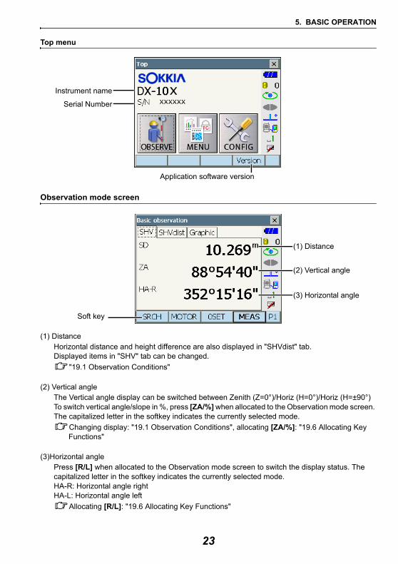
Top menu
Observation mode screen
(1) DistanceHorizontal distance and height difference are also displayed in "SHVdist" tab.Displayed items in "SHV" tab can be changed.
"19.1 Observation Conditions"
(2) Vertical angleThe Vertical angle display can be switched between Zenith (Z=0°)/Horiz (H=0°)/Horiz (H=±90°)To switch vertical angle/slope in %, press [ZA/%] when allocated to the Observation mode screen. The capitalized letter in the softkey indicates the currently selected mode.
Changing display: "19.1 Observation Conditions", allocating [ZA/%]: "19.6 Allocating Key Functions"
(3)Horizontal anglePress [R/L] when allocated to the Observation mode screen to switch the display status. The capitalized letter in the softkey indicates the currently selected mode.HA-R: Horizontal angle rightHA-L: Horizontal angle left
Allocating [R/L]: "19.6 Allocating Key Functions"
Instrument name
Serial Number
Application software version
(1) Distance
(2) Vertical angle
(3) Horizontal angle
Soft key
23
5. BASIC OPERATION
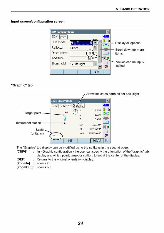
Input screen/configuration screen
"Graphic" tab
The "Graphic" tab display can be modified using the softkeys in the second page.[CNFG] : In <Graphic configuration> the user can specify the orientation of the "graphic" tab
display and which point, target or station, to set at the center of the display.[DEF.] : Returns to the original orientation display.[ZoomIn] : Zooms in.[ZoomOut] : Zooms out.
Display all options
Scroll down for more
Values can be input/
items
edited
Instrument station
Scale(units: m)
Arrow indicates north as set backsight
Target point
24
5. BASIC OPERATION
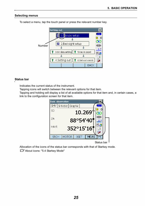
Selecting menus
To select a menu, tap the touch panel or press the relevant number key.
Status bar
Indicates the current status of the instrument. Tapping icons will switch between the relevant options for that item.Tapping and holding will display a list of all available options for that item and, in certain cases, a link to the configuration screen for that item.
Allocation of the icons of the status bar corresponds with that of Starkey mode.About icons: "5.4 Starkey Mode"
Number
Status bar
25
5. BASIC OPERATION
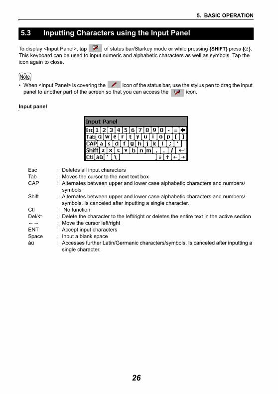
To display <Input Panel>, tap of status bar/Starkey mode or while pressing {SHIFT} press {α}. This keyboard can be used to input numeric and alphabetic characters as well as symbols. Tap the icon again to close.
• When <Input Panel> is covering the icon of the status bar, use the stylus pen to drag the input panel to another part of the screen so that you can access the icon.
Input panel
Esc : Deletes all input charactersTab : Moves the cursor to the next text boxCAP : Alternates between upper and lower case alphabetic characters and numbers/
symbolsShift : Alternates between upper and lower case alphabetic characters and numbers/
symbols. Is canceled after inputting a single character.Ctl : No functionDel/ : Delete the character to the left/right or deletes the entire text in the active section← → : Move the cursor left/rightENT : Accept input charactersSpace : Input a blank spaceáü : Accesses further Latin/Germanic characters/symbols. Is canceled after inputting a
single character.
5.3 Inputting Characters using the Input Panel
26
5. BASIC OPERATION
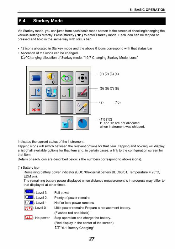
Via Starkey mode, you can jump from each basic mode screen to the screen of checking/changing the various settings directly. Press starkey { ★ } to enter Starkey mode. Each icon can be tapped or pressed and hold in the same way with status bar.
• 12 icons allocated in Starkey mode and the above 8 icons correspond with that status bar• Allocation of the icons can be changed.
Changing allocation of Starkey mode: "19.7 Changing Starkey Mode Icons"
Indicates the current status of the instrument.Tapping icons will switch between the relevant options for that item. Tapping and holding will display a list of all available options for that item and, in certain cases, a link to the configuration screen for that item.Details of each icon are described below. (The numbers correspond to above icons).
(1) Battery iconRemaining battery power indicator (BDC70/external battery BDC60/61, Temperature = 20°C, EDM on). The remaining battery power displayed when distance measurement is in progress may differ to that displayed at other times.
: Level 3 Full power: Level 2 Plenty of power remains: Level 1 Half or less power remains: Level 0 Little power remains Prepare a replacement battery.
(Flashes red and black): No power Stop operation and charge the battery.
(Red display in the center of the screen)"6.1 Battery Charging"
5.4 Starkey Mode
(1) (2) (3) (4)
(5) (6) (7) (8)
(9) (10)
(11) (12)
when instrument was shipped.11 and 12 are not allocated
27
5. BASIC OPERATION
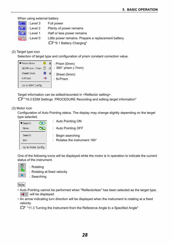
When using external battery: Level 3 Full power: Level 2 Plenty of power remains: Level 1 Half or less power remains: Level 0 Little power remains. Prepare a replacement battery.
"6.1 Battery Charging" (2) Target type icon
Selection of target type and configuration of prism constant correction value.
: Prism (0mm): 360° prism (-7mm)
: Sheet (0mm): N-Prism
Target information can be edited/recorded in <Reflector setting>."19.3 EDM Settings PROCEDURE Recording and editing target information"
(3) Motor iconConfiguration of Auto Pointing status. The display may change slightly depending on the target type selected.
: Auto Pointing ON
: Auto Pointing OFF
: Begin searching: Rotates the instrument 180°
One of the following icons will be displayed while the motor is in operation to indicate the current status of the instrument.
: Rotating: Rotating at fixed velocity: Searching
• Auto Pointing cannot be performed when "Reflectorless" has been selected as the target type. will be displayed.
• An arrow indicating turn direction will be displayed when the instrument is rotating at a fixed velocity.
"11.3 Turning the Instrument from the Reference Angle to a Specified Angle"
28
5. BASIC OPERATION
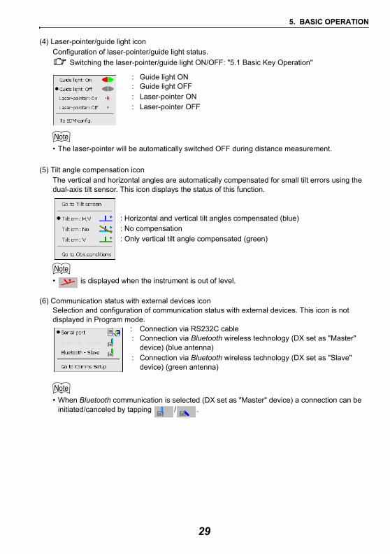
(4) Laser-pointer/guide light iconConfiguration of laser-pointer/guide light status.
Switching the laser-pointer/guide light ON/OFF: "5.1 Basic Key Operation"
: Guide light ON: Guide light OFF: Laser-pointer ON: Laser-pointer OFF
• The laser-pointer will be automatically switched OFF during distance measurement.
(5) Tilt angle compensation iconThe vertical and horizontal angles are automatically compensated for small tilt errors using the dual-axis tilt sensor. This icon displays the status of this function.
: Horizontal and vertical tilt angles compensated (blue): No compensation : Only vertical tilt angle compensated (green)
• is displayed when the instrument is out of level.
(6) Communication status with external devices iconSelection and configuration of communication status with external devices. This icon is not displayed in Program mode.
: Connection via RS232C cable: Connection via Bluetooth wireless technology (DX set as "Master"
device) (blue antenna): Connection via Bluetooth wireless technology (DX set as "Slave"
device) (green antenna)
• When Bluetooth communication is selected (DX set as "Master" device) a connection can be initiated/canceled by tapping / .
29
5. BASIC OPERATION
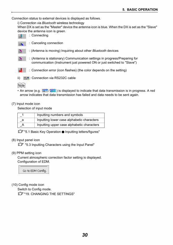
Connection status to external devices is displayed as follows.i) Connection via Bluetooth wireless technologyWhen DX is set as the "Master" device the antenna icon is blue. When the DX is set as the "Slave" device the antenna icon is green.
: Connecting
: Canceling connection
: (Antenna is moving) Inquiring about other Bluetooth devices
: (Antenna is stationary) Communication settings in progress/Preparing for communication (Instrument just powered ON or just switched to "Slave")
: Connection error (icon flashes) (the color depends on the setting)
ii) : Connection via RS232C cable
• An arrow (e.g. / ) is displayed to indicate that data transmission is in progress. A red arrow indicates that data transmission has failed and data needs to be sent again.
(7) Input mode iconSelection of input mode
"5.1 Basic Key Operation Inputting letters/figures"
(8) Input panel icon "5.3 Inputting Characters using the Input Panel"
(9) PPM setting iconCurrent atmospheric correction factor setting is displayed.Configuration of EDM.
(10) Config mode iconSwitch to Config mode.
"19. CHANGING THE SETTINGS"
_1 Inputting numbers and symbols_a Inputting lower case alphabetic characters_A Inputting upper case alphabetic characters
30
5. BASIC OPERATION
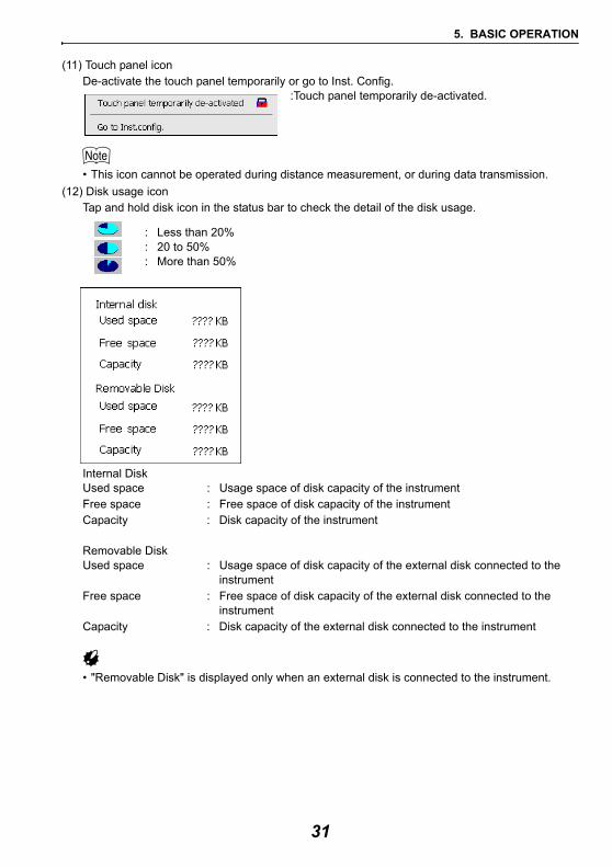
(11) Touch panel iconDe-activate the touch panel temporarily or go to Inst. Config.
:Touch panel temporarily de-activated.
• This icon cannot be operated during distance measurement, or during data transmission.(12) Disk usage icon
Tap and hold disk icon in the status bar to check the detail of the disk usage.
: Less than 20% : 20 to 50% : More than 50%
Internal DiskUsed space : Usage space of disk capacity of the instrumentFree space : Free space of disk capacity of the instrumentCapacity : Disk capacity of the instrument
Removable DiskUsed space : Usage space of disk capacity of the external disk connected to the
instrumentFree space : Free space of disk capacity of the external disk connected to the
instrumentCapacity : Disk capacity of the external disk connected to the instrument
• "Removable Disk" is displayed only when an external disk is connected to the instrument.
31
5. BASIC OPERATION
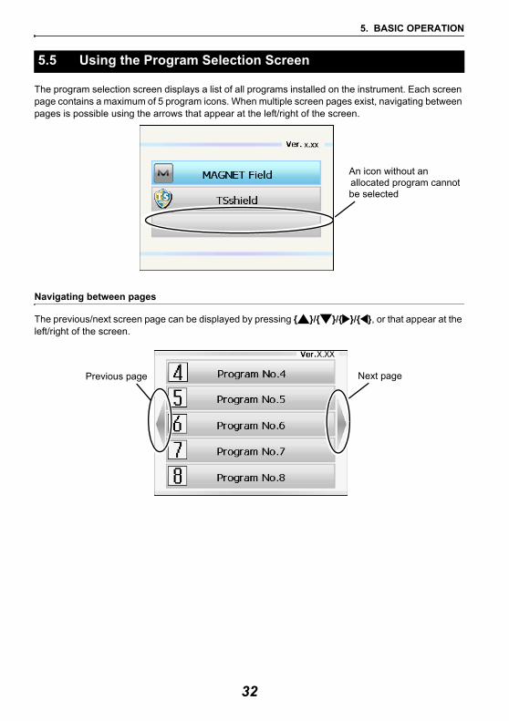
The program selection screen displays a list of all programs installed on the instrument. Each screen page contains a maximum of 5 program icons. When multiple screen pages exist, navigating between pages is possible using the arrows that appear at the left/right of the screen.
Navigating between pages
The previous/next screen page can be displayed by pressing { }/{ }/{ }/{ }, or that appear at the left/right of the screen.
5.5 Using the Program Selection Screen
An icon without an allocated program cannotbe selected
Next pagePrevious page
32
6. USING THE BATTERY
The battery was not charged at the factory. Charge the battery fully before using the instrument.
• The charger will become rather hot during use. This is normal.• Do not use to charge batteries other than those specified.• The charger is for indoor use only. Do not use outdoors.• Batteries cannot be charged, even when the charging lamp is flashing, when the temperature is
outside the charging temperature range.• Do not charge the battery just after charging is completed. Battery performance may decline.• Remove batteries from the charger before putting into storage.• When not in use, disconnect the power cable plug from the wall outlet.• Store the battery in a dry room where the temperature is within the following ranges. For long-term
storage, the battery should be charged at least once every six months.
• Batteries generate power using a chemical reaction and as a result have a limited lifetime. Even when in storage and not used for long periods, battery capacity deteriorates with the passage of time. This may result in the operating time of the battery shortening despite having been charged correctly. In this event, a new battery is required.
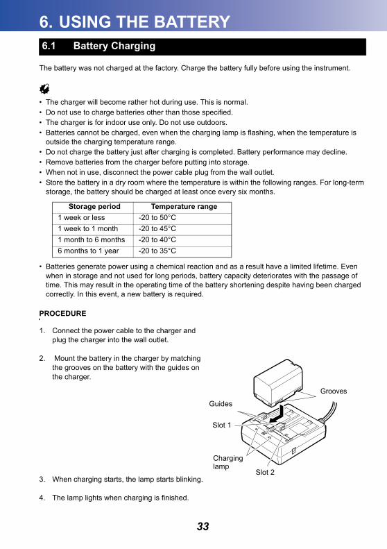
PROCEDURE
1. Connect the power cable to the charger and plug the charger into the wall outlet.
2. Mount the battery in the charger by matching the grooves on the battery with the guides on the charger.
3. When charging starts, the lamp starts blinking.
4. The lamp lights when charging is finished.
6.1 Battery Charging
Storage period Temperature range1 week or less -20 to 50°C1 week to 1 month -20 to 45°C1 month to 6 months -20 to 40°C6 months to 1 year -20 to 35°C
Guides
Slot 1
Slot 2
Charging lamp
Grooves
33
6. USING THE BATTERY
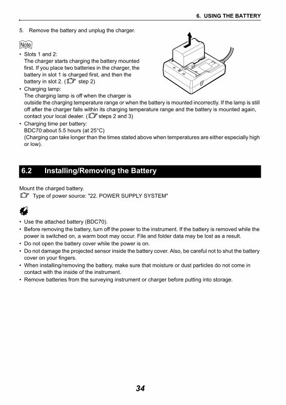
5. Remove the battery and unplug the charger.
• Slots 1 and 2:The charger starts charging the battery mounted first. If you place two batteries in the charger, the battery in slot 1 is charged first, and then the battery in slot 2. ( step 2)
• Charging lamp:The charging lamp is off when the charger is outside the charging temperature range or when the battery is mounted incorrectly. If the lamp is still off after the charger falls within its charging temperature range and the battery is mounted again, contact your local dealer. ( steps 2 and 3)
• Charging time per battery:BDC70:about 5.5 hours (at 25°C)(Charging can take longer than the times stated above when temperatures are either especially high or low).
Mount the charged battery.Type of power source: "22. POWER SUPPLY SYSTEM"
• Use the attached battery (BDC70).• Before removing the battery, turn off the power to the instrument. If the battery is removed while the
power is switched on, a warm boot may occur. File and folder data may be lost as a result.• Do not open the battery cover while the power is on.• Do not damage the projected sensor inside the battery cover. Also, be careful not to shut the battery
cover on your fingers.• When installing/removing the battery, make sure that moisture or dust particles do not come in
contact with the inside of the instrument.• Remove batteries from the surveying instrument or charger before putting into storage.
6.2 Installing/Removing the Battery
34
6. USING THE BATTERY
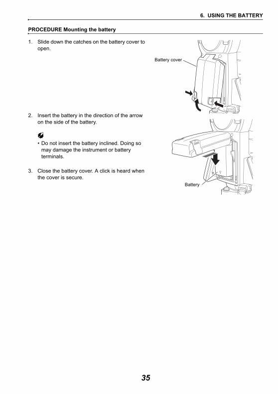
PROCEDURE Mounting the battery
1. Slide down the catches on the battery cover to open.
2. Insert the battery in the direction of the arrow on the side of the battery.
• Do not insert the battery inclined. Doing so may damage the instrument or battery terminals.
3. Close the battery cover. A click is heard when the cover is secure.
Battery cover
Battery
35
7. SETTING UP THE INSTRUMENT
• Mount the battery in the instrument before performing this operation because the instrument will tilt slightly if the battery is mounted after levelling.
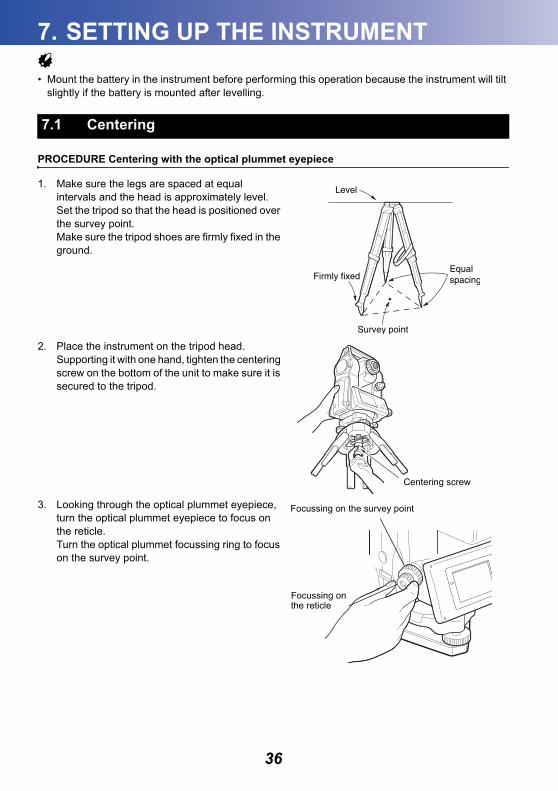
PROCEDURE Centering with the optical plummet eyepiece
1. Make sure the legs are spaced at equal intervals and the head is approximately level.Set the tripod so that the head is positioned over the survey point.Make sure the tripod shoes are firmly fixed in the ground.
2. Place the instrument on the tripod head.Supporting it with one hand, tighten the centering screw on the bottom of the unit to make sure it is secured to the tripod.
3. Looking through the optical plummet eyepiece, turn the optical plummet eyepiece to focus on the reticle.Turn the optical plummet focussing ring to focus on the survey point.
7.1 Centering
Centering screw
Focussing on the survey point
Focussing onthe reticle
36
7. SETTING UP THE INSTRUMENT
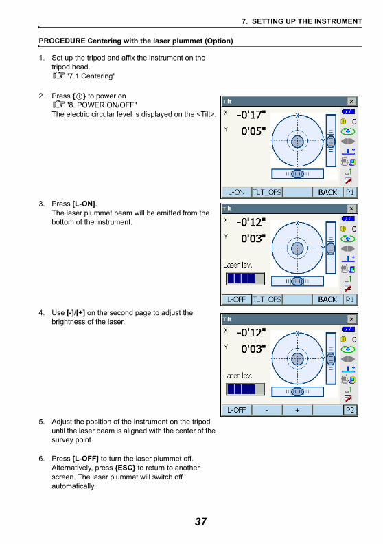
PROCEDURE Centering with the laser plummet (Option)
1. Set up the tripod and affix the instrument on the tripod head.
"7.1 Centering"
2. Press { } to power on"8. POWER ON/OFF"
The electric circular level is displayed on the <Tilt>.
3. Press [L-ON].The laser plummet beam will be emitted from the bottom of the instrument.
4. Use [-]/[+] on the second page to adjust the brightness of the laser.
5. Adjust the position of the instrument on the tripod until the laser beam is aligned with the center of the survey point.
6. Press [L-OFF] to turn the laser plummet off.Alternatively, press {ESC} to return to another screen. The laser plummet will switch off automatically.
37
7. SETTING UP THE INSTRUMENT
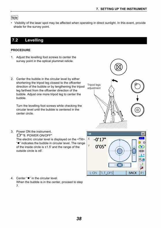
• Visibility of the laser spot may be affected when operating in direct sunlight. In this event, provide shade for the survey point.
PROCEDURE
1. Adjust the levelling foot screws to center the survey point in the optical plummet reticle.
2. Center the bubble in the circular level by either shortening the tripod leg closest to the offcenter direction of the bubble or by lengthening the tripod leg farthest from the offcenter direction of the bubble. Adjust one more tripod leg to center the bubble.
Turn the levelling foot screws while checking the circular level until the bubble is centered in the center circle.
3. Power ON the instrument."8. POWER ON/OFF"
The electric circular level is displayed on the <Tilt>.“ ” indicates the bubble in circular level. The range of the inside circle is ±1.5' and the range of the outside circle is ±6'.
4. Center “ ” in the circular level.When the bubble is in the center, proceed to step 7.
7.2 Levelling
Tripod legsadjustment
38
7. SETTING UP THE INSTRUMENT
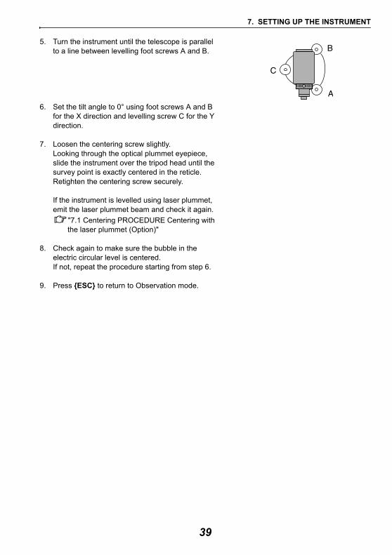
5. Turn the instrument until the telescope is parallel to a line between levelling foot screws A and B.
6. Set the tilt angle to 0° using foot screws A and B for the X direction and levelling screw C for the Y direction.
7. Loosen the centering screw slightly.Looking through the optical plummet eyepiece, slide the instrument over the tripod head until the survey point is exactly centered in the reticle.Retighten the centering screw securely.
If the instrument is levelled using laser plummet, emit the laser plummet beam and check it again.
"7.1 Centering PROCEDURE Centering with the laser plummet (Option)"
8. Check again to make sure the bubble in the electric circular level is centered.If not, repeat the procedure starting from step 6.
9. Press {ESC} to return to Observation mode.
39
8. POWER ON/OFF
• When the power cannot be switched ON or the power is soon turned OFF even though the battery is mounted, there may be almost no battery power remaining. Replace it with a fully charged battery.
"20. WARNING AND ERROR MESSAGES"
PROCEDURE Power ON
1. Press { }.When the power is switched on, the <Tilt> is displayed.
"7.2 Levelling" step 3Press {ESC} to go Observation mode screen.
If "Out of range" is displayed, the instrument tilt sensor is indicating that the instrument is out of level. Level the instrument once again using circular level, then display <Tilt>.Press and hold Tilt angle compensation icon on status bar or in Starkey mode, then select "Go to Tilt screen".
"5.4 Starkey Mode" (5) Tilt angle compensation icon
• "Tilt crn." in "Obs. condition" should be set to "No" if the display is unsteady due to vibration or strong wind. "19.1 Observation Conditions"
Resume functionThe Resume function redisplays the screen appearing before the instrument was powered OFF when the instrument is powered back ON. All parameter settings are also saved. Even if remaining battery power is completely depleted, this function will remain active for 1 minute, after which it is canceled. Replace a depleted battery as soon as possible.
PROCEDURE Power OFF
1. Press and hold (about 1sec) { }.
• When there is almost no battery power remaining, the battery icon in the status bar will start to blink.In this event, stop measurement, switch off the power and charge the battery or replace with a fully charged battery.
• To save power, power to the instrument is automatically cut off if it is not operated for a fixed period of time. This time period can be set in "Power off" in <Inst.config.>.
"19.2 Instrument Configuration"
40
8. POWER ON/OFF
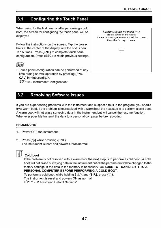
When using for the first time, or after performing a cold boot, the screen for configuring the touch panel will be displayed.
Follow the instructions on the screen. Tap the cross-hairs at the center of the display with the stylus pen. Tap 5 times. Press {ENT} to complete touch panel configuration. Press {ESC} to retain previous settings.
• Touch panel configuration can be performed at any time during normal operation by pressing [PNL CAL] in <Inst.config.>.
"19.2 Instrument Configuration"
If you are experiencing problems with the instrument and suspect a fault in the program, you should try a warm boot. If the problem is not resolved with a warm boot the next step is to perform a cold boot. A warm boot will not erase surveying data in the instrument but will cancel the resume function. Whenever possible transmit the data to a personal computer before rebooting.
PROCEDURE
1. Power OFF the instrument.
2. Press { } while pressing {ENT}. The instrument is reset and powers ON as normal.
Cold bootIf the problem is not resolved with a warm boot the next step is to perform a cold boot. A cold boot will not erase surveying data in the instrument but all the parameters will be changed to the factory settings. If the data in the memory is necessary, BE SURE TO TRANSFER IT TO A PERSONAL COMPUTER BEFORE PERFORMING A COLD BOOT.To perform a cold boot, while holding { }, and {S.P.}, press { }.The instrument is reset and powers ON as normal.
"19.11 Restoring Default Settings"
8.1 Configuring the Touch Panel
8.2 Resolving Software Issues
41
8. POWER ON/OFF
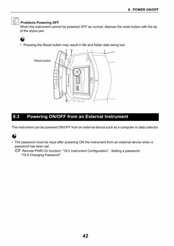
Problems Powering OFFWhen the instrument cannot be powered OFF as normal, depress the reset button with the tip of the stylus pen.
• Pressing the Reset button may result in file and folder data being lost.
The instrument can be powered ON/OFF from an external device such as a computer or data collector.
• The password must be input after powering ON the instrument from an external device when a password has been set.
Remote PWR-On function: "19.2 Instrument Configuration", Setting a password: "19.9 Changing Password"
8.3 Powering ON/OFF from an External Instrument
Reset button
42
9. CONNECTING TO EXTERNAL DEVICES
The instrument supports Bluetooth wireless technology and RS232C for communication with data collectors etc. Inputting/outputting data is also possible by inserting a USB memory or by connecting to a USB device. Read this manual in conjunction with the operator’s manual for the relevant external device.• When doing Bluetooth communication, read "4.3 Bluetooth Wireless Technology".
The Bluetooth module incorporated in the instrument can be used for communication with Bluetooth devices such as data collectors.
Bluetooth connectionsCommunication between a pair of Bluetooth devices requires one device to be set as the "Master" and the other as the "Slave". To initiate connections from the DX side, set the DX as the "Master" device. To initiate connections from the paired device side, set the DX as the "Slave" device. The factory setting is "Slave".
PROCEDURE Necessary settings for Bluetooth communication
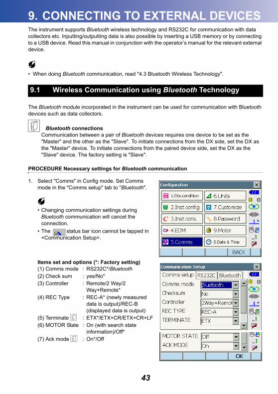
1. Select "Comms" in Config mode. Set Comms mode in the "Comms setup" tab to "Bluetooth".
• Changing communication settings during Bluetooth communication will cancel the connection.
• The status bar icon cannot be tapped in <Communication Setup>.
Items set and options (*: Factory setting)(1) Comms mode : RS232C*/Bluetooth(2) Check sum : yes/No*(3) Controller : Remote/2 Way/2
Way+Remote*(4) REC Type : REC-A* (newly measured
data is output)/REC-B (displayed data is output)
(5) Terminate : ETX*/ETX+CR/ETX+CR+LF(6) MOTOR State : On (with search state
information)/Off* (7) Ack mode : On*/Off
9.1 Wireless Communication using Bluetooth Technology
43
9. CONNECTING TO EXTERNAL DEVICES
TerminateSelect the option Off or On for carrige return (CR) and line feed when collecting measurement data with a computer.
ACK modeWhen communicating to an external device, the protocol for handshaking can omit the [ACK] coming from the external device so data is not sent again.On : StandardOff : Omit the [ACK]
• Setting’ (5) and (7) are for an instrument using GTS commands.
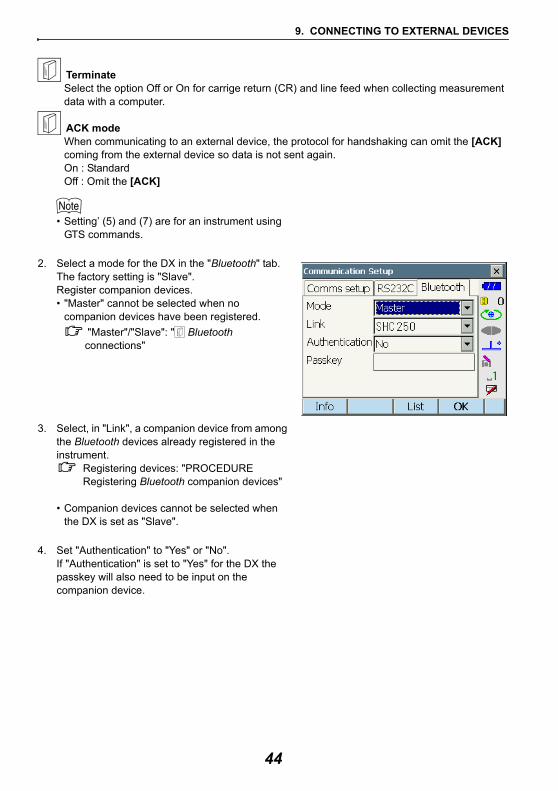
2. Select a mode for the DX in the "Bluetooth" tab.The factory setting is "Slave".Register companion devices.• "Master" cannot be selected when no
companion devices have been registered. "Master"/"Slave": " Bluetooth connections"
3. Select, in "Link", a companion device from among the Bluetooth devices already registered in the instrument.
Registering devices: "PROCEDURE Registering Bluetooth companion devices"
• Companion devices cannot be selected when the DX is set as "Slave".
4. Set "Authentication" to "Yes" or "No".If "Authentication" is set to "Yes" for the DX the passkey will also need to be input on the companion device.
44
9. CONNECTING TO EXTERNAL DEVICES
5. When "Authentication" is set to "Yes", input the same passkey as that for the intended companion device. Even if "Authentication" is set to "No", a passkey is requested when authentication is set on the companion device being used.
• Up to 16 numeral characters can be input. Input characters will be displayed as asterisks (e.g. "*****"). The passkey was set to "0123" at the factory.
6. Press [OK] to finish settings.
PROCEDURE Registering Bluetooth companion devices
1. Power on the companion device.
2. Select "Bluetooth" in "Comms mode" in the "Comms setup" tab.
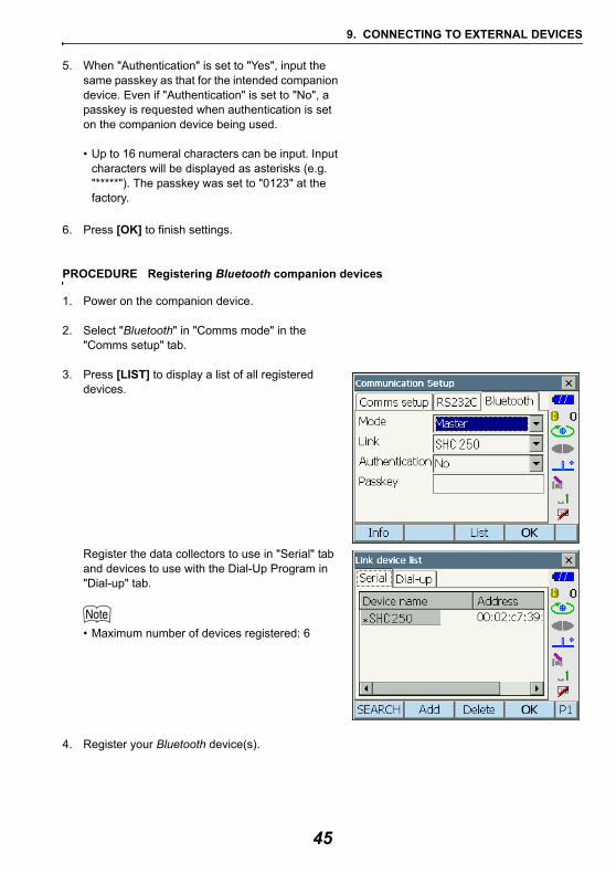
3. Press [LIST] to display a list of all registered devices.
Register the data collectors to use in "Serial" tab and devices to use with the Dial-Up Program in "Dial-up" tab.
• Maximum number of devices registered: 6
4. Register your Bluetooth device(s).
45
9. CONNECTING TO EXTERNAL DEVICES
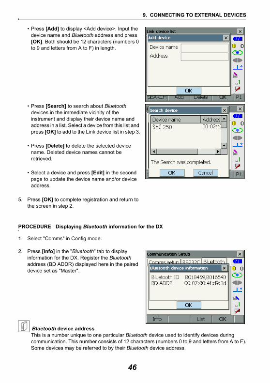
• Press [Add] to display <Add device>. Input the device name and Bluetooth address and press [OK]. Both should be 12 characters (numbers 0 to 9 and letters from A to F) in length.
• Press [Search] to search about Bluetooth devices in the immediate vicinity of the instrument and display their device name and address in a list. Select a device from this list and press [OK] to add to the Link device list in step 3.
• Press [Delete] to delete the selected device name. Deleted device names cannot be retrieved.
• Select a device and press [Edit] in the second page to update the device name and/or device address.
5. Press [OK] to complete registration and return to the screen in step 2.
PROCEDURE Displaying Bluetooth information for the DX
1. Select "Comms" in Config mode.
2. Press [Info] in the "Bluetooth" tab to display information for the DX. Register the Bluetooth address (BD ADDR) displayed here in the paired device set as "Master".
Bluetooth device addressThis is a number unique to one particular Bluetooth device used to identify devices during communication. This number consists of 12 characters (numbers 0 to 9 and letters from A to F).Some devices may be referred to by their Bluetooth device address.
46
9. CONNECTING TO EXTERNAL DEVICES
• Bluetooth communication causes instrument battery power to be depleted at a rate higher than that for normal operation.
• Check that the companion device (data collector, computer, or cellular phone etc.) is turned on and the relevant Bluetooth settings are complete.
• All communication settings will be changed to factory settings when a cold boot is performed. Comms setup will need to be performed again.
"9.1 Wireless Communication using Bluetooth Technology"
PROCEDURE Bluetooth communication
1. Complete the necessary DX settings for Bluetooth communication.
"9.1 Wireless Communication using Bluetooth Technology"
2. Start communicationWhen DX is set as the "Master" device, the [Connect] softkey is allocated to the fourth page of Observation mode. When [Connect] is pressed the DX searches for the device selected in "Link" and a connection starts. When a connection has been successfully established is displayed in the status bar.The establishing of a connection can also be initiated by tapping in the status bar.
Communication status:"5.4 Starkey Mode"
• When DX is set as the "Slave" device, the establishing of a connection can only be initiated/canceled by the companion device set as "Master".
3. Press [Cancel] in the fourth page of Observation mode to terminate the connection.A connection can also be terminated by tapping
in the status bar.
9.2 Communication between the DX and Companion Device
47
9. CONNECTING TO EXTERNAL DEVICES
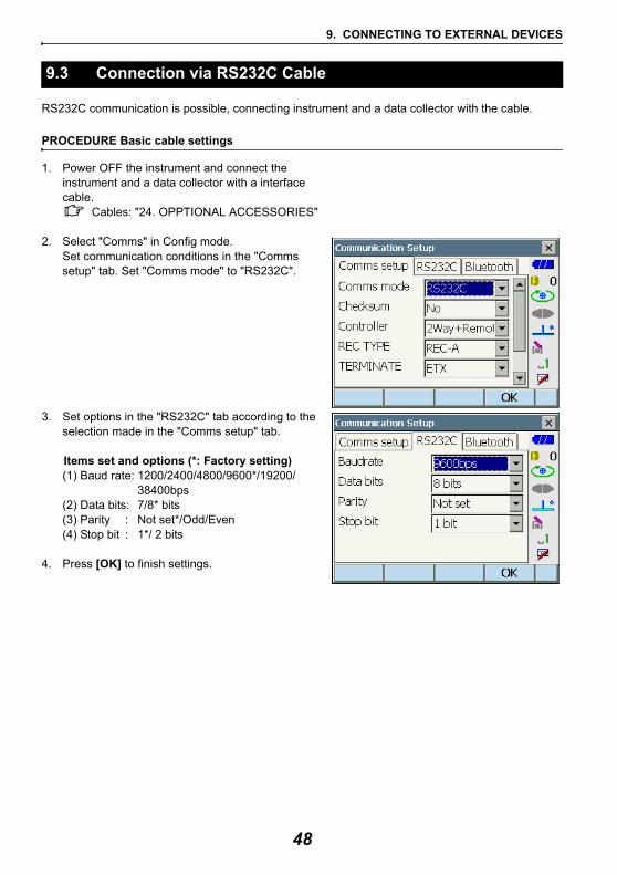
RS232C communication is possible, connecting instrument and a data collector with the cable.
PROCEDURE Basic cable settings
1. Power OFF the instrument and connect the instrument and a data collector with a interface cable.
Cables: "24. OPPTIONAL ACCESSORIES"
2. Select "Comms" in Config mode. Set communication conditions in the "Comms setup" tab. Set "Comms mode" to "RS232C".
3. Set options in the "RS232C" tab according to the selection made in the "Comms setup" tab.
Items set and options (*: Factory setting)(1) Baud rate: 1200/2400/4800/9600*/19200/
38400bps(2) Data bits: 7/8* bits(3) Parity : Not set*/Odd/Even(4) Stop bit : 1*/ 2 bits
4. Press [OK] to finish settings.
9.3 Connection via RS232C Cable
48
9. CONNECTING TO EXTERNAL DEVICES
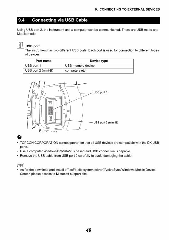
Using USB port 2, the instrument and a computer can be communicated. There are USB mode and Mobile mode.
USB portThe instrument has two different USB ports. Each port is used for connection to different types of devices.
• TOPCON CORPORATION cannot guarantee that all USB devices are compatible with the DX USB ports.
• Use a computer WindowsXP/Vista/7 is based and USB connection is capable.• Remove the USB cable from USB port 2 carefully to avoid damaging the cable.
• As for the download and install of "exFat file system driver"/ActiveSync/Windows Mobile Device Center, please access to Microsoft support site.
9.4 Connecting via USB Cable
Port name Device typeUSB port 1 USB memory device.USB port 2 (mini-B) computers etc.
USB port 1
USB port 2 (mini-B)
49
9. CONNECTING TO EXTERNAL DEVICES
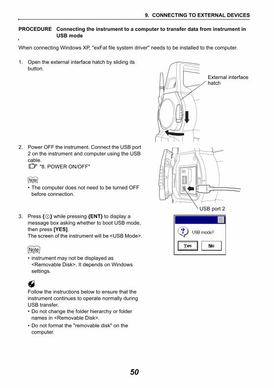
PROCEDURE Connecting the instrument to a computer to transfer data from instrument in USB mode
When connecting Windows XP, "exFat file system driver" needs to be installed to the computer.
1. Open the external interface hatch by sliding its button.
2. Power OFF the instrument. Connect the USB port 2 on the instrument and computer using the USB cable.
"8. POWER ON/OFF"
• The computer does not need to be turned OFF before connection.
3. Press { } while pressing {ENT} to display a message box asking whether to boot USB mode, then press [YES].The screen of the instrument will be <USB Mode>.
• instrument may not be displayed as <Removable Disk>. It depends on Windows settings.
Follow the instructions below to ensure that the instrument continues to operate normally during USB transfer.• Do not change the folder hierarchy or folder
names in <Removable Disk>.• Do not format the "removable disk" on the
computer.
External interface hatch
USB port 2
50
9. CONNECTING TO EXTERNAL DEVICES
4. Perform "Safely Remove Hardware" in the task bar and disconnect the USB cable.
5. Press { } and hold (about 1sec) to turn off the instrument to exit USB mode connection.
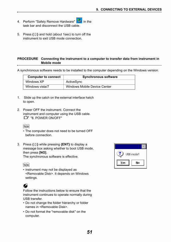
PROCEDURE Connecting the instrument to a computer to transfer data from instrument in Mobile mode
A synchronous software needs to be installed to the computer depending on the Windows version.
1. Slide up the catch on the external interface hatch to open.
2. Power OFF the instrument. Connect the instrument and computer using the USB cable.
"8. POWER ON/OFF"
• The computer does not need to be turned OFF before connection.
3. Press { } while pressing {ENT} to display a message box asking whether to boot USB mode, then press [NO].The synchronous software is effective.
• instrument may not be displayed as <Removable Disk>. It depends on Windows settings.
Follow the instructions below to ensure that the instrument continues to operate normally during USB transfer.• Do not change the folder hierarchy or folder
names in <Removable Disk>.• Do not format the "removable disk" on the
computer.
Computer to connect Synchronous softwareWindows XP ActiveSyncWindows vista/7 Windows Mobile Device Center
51
9. CONNECTING TO EXTERNAL DEVICES
4. If synchronous software displays a partner setting screen on the computer and asks whether to set a partner device, press [NO].
• A partner setting screen may not be displayed depending on the synchronous software settings.
5. Disconnect the USB cable to exit mobile mode connection.
Saving data in a USB memory or importing data from a memory is possible using the particular program on program mode.
USB ports: "9.4 Connecting via USB Cable"
• When reading/writing data, do not remove the USB memory.
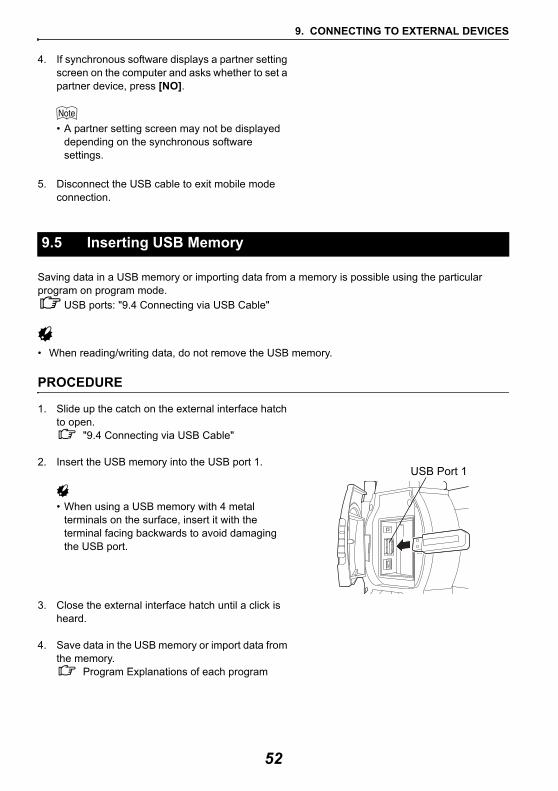
PROCEDURE
1. Slide up the catch on the external interface hatch to open.
"9.4 Connecting via USB Cable"
2. Insert the USB memory into the USB port 1.
• When using a USB memory with 4 metal terminals on the surface, insert it with the terminal facing backwards to avoid damaging the USB port.
3. Close the external interface hatch until a click is heard.
4. Save data in the USB memory or import data from the memory.
Program Explanations of each program
9.5 Inserting USB Memory
USB Port 1
52
10.TARGET SIGHTING
A target can be automatically sighted using the Auto Pointing function or manually sighted by the operator using the sighting collimatorand telescope.When Auto Pointing is performed, the image sensor on the instrument detects the light beam reflected from the target (prism or reflective sheet target), the offset between the target and telescope reticle is calculated by image processing, then the angle measurement value obtained from the encoder is compensated. There is a possibility that the target and telescope reticle are not aligned.Caution• The instrument emits a laser beam until the prism is sighted.
• Auto Pointing can only be performed when a prism or sheet is used as the target. For reflectorless measurement, the target must be sighted manually.
• Use designated reflective prisms/reflective sheets for higher precision measurement. Make sure reflector type and aperture/sheet size are set correctly in <EDM configurations>.
• Detach the handle if the prism is located at the zenith."4.1 Parts of the Instrument Handle Detaching/attaching the Handle"
• Auto Pointing may take long time if the prism is located at the zenith. In this case, use optional accessory diagonal eyepiece (DE27) and manually sight the target.
"10.3 Manually Sighting the Target"• If more than one prism is located in the field of sight during Auto Pointing, an operation error will
occur and the instrument will not be able to find the target.• A prism beyond glass cannot be searched because a measurement error occurs.• If an obstacle blocks the laser beam path between the instrument and the prism, instrument cannot
find the target correctly.• If strong light shines directly into the objective lens, measurement cannot be performed correctly.• Position every target in alignment with the objective lens to eliminate the error caused by tilted
target.Facing the 360° prism toward the instrument: "26.1 High Accuracy with the 360° Prism"
• The following table suggests what size target to use for different distances when performing Auto Pointing with a reflective sheet target.
Distance Target size 5 to 15m RS10 (10mm)5 to 30m RS30 (30mm)5 to 40m RS50 (50mm)10 to 50m RS90 (90mm)
Offset of X direction
Offs
et
of Y
dire
ctio
n
53
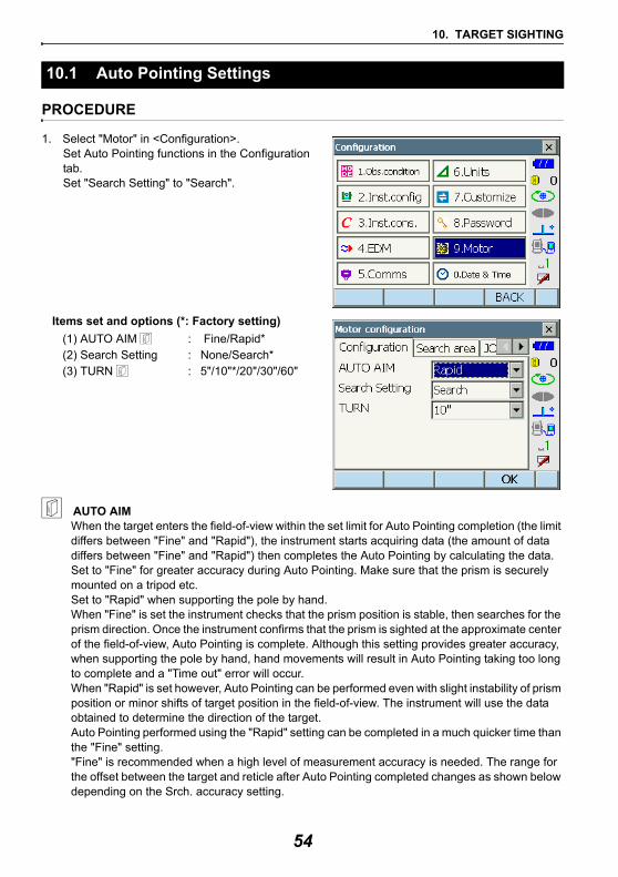
10. TARGET SIGHTING
PROCEDURE
1. Select "Motor" in <Configuration>.Set Auto Pointing functions in the Configuration tab. Set "Search Setting" to "Search".
Items set and options (*: Factory setting)(1) AUTO AIM : Fine/Rapid*(2) Search Setting : None/Search*(3) TURN : 5"/10"*/20"/30"/60"
AUTO AIMWhen the target enters the field-of-view within the set limit for Auto Pointing completion (the limit differs between "Fine" and "Rapid"), the instrument starts acquiring data (the amount of data differs between "Fine" and "Rapid") then completes the Auto Pointing by calculating the data.Set to "Fine" for greater accuracy during Auto Pointing. Make sure that the prism is securely mounted on a tripod etc. Set to "Rapid" when supporting the pole by hand.When "Fine" is set the instrument checks that the prism position is stable, then searches for the prism direction. Once the instrument confirms that the prism is sighted at the approximate center of the field-of-view, Auto Pointing is complete. Although this setting provides greater accuracy, when supporting the pole by hand, hand movements will result in Auto Pointing taking too long to complete and a "Time out" error will occur.When "Rapid" is set however, Auto Pointing can be performed even with slight instability of prism position or minor shifts of target position in the field-of-view. The instrument will use the data obtained to determine the direction of the target.Auto Pointing performed using the "Rapid" setting can be completed in a much quicker time than the "Fine" setting."Fine" is recommended when a high level of measurement accuracy is needed. The range for the offset between the target and reticle after Auto Pointing completed changes as shown below depending on the Srch. accuracy setting.
10.1 Auto Pointing Settings
54
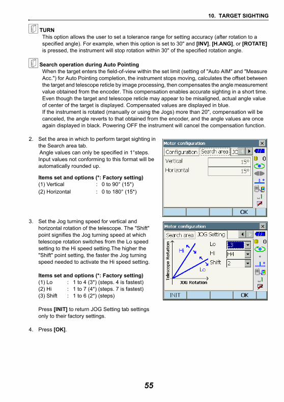
10. TARGET SIGHTING
TURN This option allows the user to set a tolerance range for setting accuracy (after rotation to a specified angle). For example, when this option is set to 30" and [INV], [H.ANG], or [ROTATE] is pressed, the instrument will stop rotation within 30" of the specified rotation angle.
Search operation during Auto PointingWhen the target enters the field-of-view within the set limit (setting of "Auto AIM" and "Measure Acc.") for Auto Pointing completion, the instrument stops moving, calculates the offset between the target and telescope reticle by image processing, then compensates the angle measurement value obtained from the encoder. This compensation enables accurate sighting in a short time. Even though the target and telescope reticle may appear to be misaligned, actual angle value of center of the target is displayed. Compensated values are displayed in blue.If the instrument is rotated (manually or using the Jogs) more than 20", compensation will be canceled, the angle reverts to that obtained from the encoder, and the angle values are once again displayed in black. Powering OFF the instrument will cancel the compensation function.
2. Set the area in which to perform target sighting in the Search area tab. Angle values can only be specified in 1°steps. Input values not conforming to this format will be automatically rounded up.
Items set and options (*: Factory setting)(1) Vertical : 0 to 90° (15*)(2) Horizontal : 0 to 180° (15*)
3. Set the Jog turning speed for vertical and horizontal rotation of the telescope. The "Shift" point signifies the Jog turning speed at which telescope rotation switches from the Lo speed setting to the Hi speed setting.The higher the "Shift" point setting, the faster the Jog turning speed needed to activate the Hi speed setting.
Items set and options (*: Factory setting)(1) Lo : 1 to 4 (3*) (steps. 4 is fastest)(2) Hi : 1 to 7 (4*) (steps. 7 is fastest)(3) Shift : 1 to 6 (2*) (steps)
Press [INIT] to return JOG Setting tab settings only to their factory settings.
4. Press [OK].
55
10. TARGET SIGHTING
PROCEDURE
1. Use the sighting collimator to aim the objective lens in the general direction of the target. The vertical and horizontal Jogs can be used for precise adjustments of the instrument and telescope
JOG Setting tab: "10.1 Auto Pointing Settings" step 3.
2. Press [SRCH] in any Observation mode screen. The telescope and top half of the instrument rotate and target auto-search begins. When the target is found, the instrument sights the prism and stops. Allocating the [SRCH] softkey:
"19.6 Allocating Key Functions"
10.2 Auto-Pointing Function for Target Sighting
56
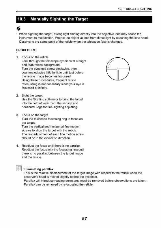
10. TARGET SIGHTING
• When sighting the target, strong light shining directly into the objective lens may cause the instrument to malfunction. Protect the objective lens from direct light by attaching the lens hood.Observe to the same point of the reticle when the telescope face is changed.
PROCEDURE
1. Focus on the reticleLook through the telescope eyepiece at a bright and featureless background.Turn the eyepiece screw clockwise, then counterclockwise little by little until just before the reticle image becomes focussed.Using these procedures, frequent reticle refocussing is not necessary since your eye is focussed at infinity.
2. Sight the targetUse the Sighting collimator to bring the target into the field of view. Turn the vertical and horizontal Jogs for fine sighting adjusting.
3. Focus on the targetTurn the telescope focussing ring to focus on the target.Turn the vertical and horizontal fine motion screws to align the target with the reticle.The last adjustment of each fine motion screw should be in the clockwise direction.
4. Readjust the focus until there is no parallaxReadjust the focus with the focussing ring until there is no parallax between the target image and the reticle.
Eliminating parallaxThis is the relative displacement of the target image with respect to the reticle when the observer’s head is moved slightly before the eyepiece.Parallax will introduce reading errors and must be removed before observations are taken. Parallax can be removed by refocussing the reticle.
10.3 Manually Sighting the Target
57

10. TARGET SIGHTING
Sighting manuallyWhen sighting manually, set "Search Setting" to "None" in <Motor Configuration> Configuration tab, then use the Sighting collimator to bring the target into the field of view. When the target is in the field-of-view, use the Jogs to make fine adjustments and accurately sight the center of the prism.It is recommended that a slow Jog turning speed is used for greater stability when performing fine adjustments.
58
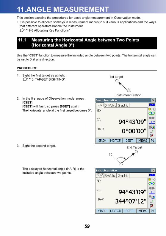
11.ANGLE MEASUREMENT
This section explains the procedures for basic angle measurement in Observation mode.• It is possible to allocate softkeys in measurement menus to suit various applications and the waysthat different operators handle the instrument."19.6 Allocating Key Functions"
Use the “0SET” function to measure the included angle between two points. The horizontal angle can be set to 0 at any direction.
PROCEDURE
1. Sight the first target as at right."10. TARGET SIGHTING"
2. In the first page of Observation mode, press [0SET].[0SET] will flash, so press [0SET] again.The horizontal angle at the first target becomes 0°.
3. Sight the second target.
The displayed horizontal angle (HA-R) is the included angle between two points.
11.1 Measuring the Horizontal Angle between Two Points (Horizontal Angle 0°)
59
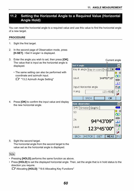
11. ANGLE MEASUREMENT
You can reset the horizontal angle to a required value and use this value to find the horizontal angle of a new target.
PROCEDURE
1. Sight the first target.
2. In the second page of Observation mode, press [H-SET]. <Set H angle> is displayed.
3. Enter the angle you wish to set, then press [OK].The value that is input as the horizontal angle is displayed.
• The same setting can also be performed with coordinate and azimuth input.
"13.2 Azimuth Angle Setting"
4. Press [OK] to confirm the input value and display the new horizontal angle.
5. Sight the second target.The horizontal angle from the second target to the value set as the horizontal angle is displayed.
• Pressing [HOLD] performs the same function as above.• Press [HOLD] to set the displayed horizontal angle. Then, set the angle that is in hold status to the
direction you require.Allocating [HOLD]: "19.6 Allocating Key Functions"
11.2 Setting the Horizontal Angle to a Required Value (Horizontal Angle Hold)
Current angle
60
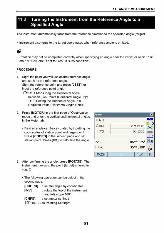
11. ANGLE MEASUREMENT
The instrument automatically turns from the reference direction to the specified angle (target).
• instrument also turns to the target coordinates when reference angle is omitted.
• Rotation may not be completed correctly when specifiying an angle near the zenith or nadir if "Tilt crn." or "Coll. crn" is set to "Yes" in "Obs.condition".
PROCEDURE
1. Sight the point you will use as the reference angle and set it as the reference angle. Sight the reference point and press [0SET], or input the reference point angle.
"11.1 Measuring the Horizontal Angle between Two Points (Horizontal Angle 0°)"/"11.2 Setting the Horizontal Angle to a Required Value (Horizontal Angle Hold)"
2. Press [MOTOR] in the first page of Observation mode and enter the vertical and horizontal angles in the Motor tab.
• Desired angle can be calculated by inputting the coordinates of station point and target point. Press [COORD] in the second page and set station point. Press [OK] to calculate the angle.
3. After confirming the angle, press [ROTATE]. The instrument moves to the point (target) entered in step 2.
• The following operation can be select in the second page.[COORD] : set the angle by coordinates[INV]: : rotate the top of the instrument
and telescope 180°[CNFG]: : set motor settings
"10.1 Auto Pointing Settings"
11.3 Turning the Instrument from the Reference Angle to a Specified Angle
61
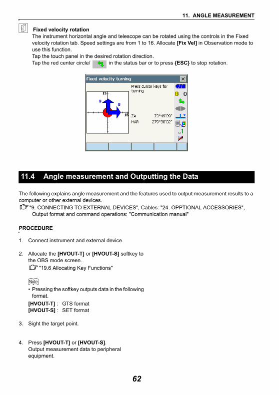
11. ANGLE MEASUREMENT
Fixed velocity rotationThe instrument horizontal angle and telescope can be rotated using the controls in the Fixed velocity rotation tab. Speed settings are from 1 to 16. Allocate [Fix Vel] in Observation mode to use this function.Tap the touch panel in the desired rotation direction.Tap the red center circle/ in the status bar or to press {ESC} to stop rotation.
The following explains angle measurement and the features used to output measurement results to a computer or other external devices.
"9. CONNECTING TO EXTERNAL DEVICES", Cables: "24. OPPTIONAL ACCESSORIES", Output format and command operations: "Communication manual"
PROCEDURE
1. Connect instrument and external device.
2. Allocate the [HVOUT-T] or [HVOUT-S] softkey to the OBS mode screen.
"19.6 Allocating Key Functions"
• Pressing the softkey outputs data in the following format.
[HVOUT-T] : GTS format[HVOUT-S] : SET format
3. Sight the target point.
4. Press [HVOUT-T] or [HVOUT-S].Output measurement data to peripheral equipment.
11.4 Angle measurement and Outputting the Data
62
12.DISTANCE MEASUREMENT
Perform the following settings as preparation for distance measurement in Observation mode.• Distance measurement mode• Target type• Prism constant correction value• (Target) Aperture• ppm• Search area• Auto Pointing"10.1 Auto Pointing Settings", "19.3 EDM Settings" • It is possible to allocate softkeys in measurement menus to suit various applications and the ways
that different operators handle the instrument."19.6 Allocating Key Functions"
Caution• When using the laser-pointer function, be sure to turn OFF the output laser after distance
measurement is completed. Even if distance measurement is canceled, the laser-pointer function is still operating and the laser beam continues to be emitted.
• Make sure that the target setting on the instrument matches the type of target used. The instrument automatically adjusts the intensity of the laser beam and switches the distance measurement display range to match the type of target used. If the target does not correspond to the target settings, accurate measurement results cannot be obtained.
• Accurate measurement results cannot be obtained if the objective lens is dirty. Dust it off with the lens brush first, to remove minute particles. Then, after providing a little condensation by breathing on the lens, wipe it off with the wiping cloth.
• During reflectorless measurement, if an object obstructs the light beam used for measurement or an object with a high reflective factor (metal or white surface) is positioned behind the target, accurate measurement results may not be received.
• Scintillation may affect the accuracy of distance measurement results. Should this occur, repeat measurement several times and use the averaged value of the obtained results.
Check to make sure that sufficient reflected light is returned by the target sighted by the telescope. Checking the returned signal is particularly useful when performing long distance measurements.
Caution• The laser beam is emitted during returned signal checking.
• When the light intensity is sufficient even though the center of the reflective prism and the reticle are slightly misaligned (short distance etc.), “ ” will be displayed in some cases, but in fact, accurate measurement is impossible. Therefore make sure that the target center is sighted correctly.
12.1 Returned Signal Checking
63
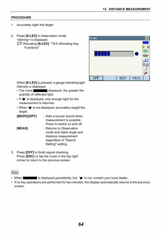
12. DISTANCE MEASUREMENT
PROCEDURE
1. Accurately sight the target.
2. Press [S-LEV] in observation mode.<Aiming> is displayed.
Allocating [S-LEV]: "19.6 Allocating Key Functions"
When [S-LEV] is pressed, a gauge indicating light intensity is displayed.• The more displayed, the greater the
quantity of reflected light.• If “ ” is displayed, only enough light for the
measurement is returned.• When “ ” is not displayed, accurately resight the
target. [BEEP]/[OFF] : Sets a buzzer sound when
measurement is possible. Press to switch on and off.
[MEAS] : Returns to Observation mode and starts angle and distance measurement regardless of "Search Setting" setting.
3. Press [OFF] to finish signal checking.Press {ESC} or tap the cross in the top-right corner to return to the previous screen.
• When is displayed persistently, but “ ” is not, contact your local dealer.• If no key operations are performed for two minutes, the display automatically returns to the previous
screen.
64
12. DISTANCE MEASUREMENT
The color and flashing speed of the guide light indicates the status of the instrument and can be known when the user is located at a distance from the instrument.
Switching the guide light ON/OFF "5.1 Basic Key Operation"
• The pattern of the guide light can be changed."19.2 Instrument Configuration"
• Even if the guide light is set to ON, the guide light is OFF during distance measurement with the target type "N-Prism" or returned signal checking.
Guide light status and meaningStatus of the instrument
12.2 Using the Guide Light in Distance Measurement
Light status MeaningSlow flashing (Red and green simultaneously)
Waiting
Fast flashing (Red and green simultaneously)
Searching in progressMeasuring (continuous measurement)Returned signal checking in progress
Green and red alternate flashingDistance measurement error (no signal, sighting error)Search error (error screen only)
65
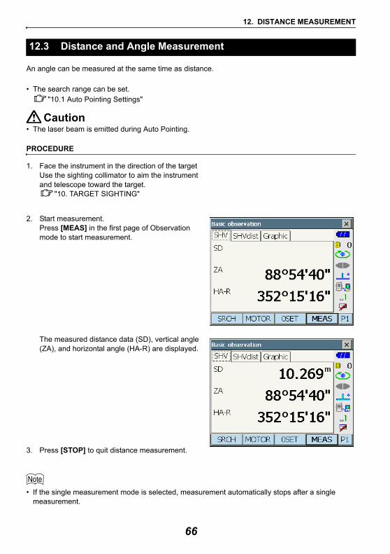
12. DISTANCE MEASUREMENT
An angle can be measured at the same time as distance.
• The search range can be set."10.1 Auto Pointing Settings"
Caution• The laser beam is emitted during Auto Pointing.
PROCEDURE
1. Face the instrument in the direction of the targetUse the sighting collimator to aim the instrument and telescope toward the target.
"10. TARGET SIGHTING"
2. Start measurement.Press [MEAS] in the first page of Observation mode to start measurement.
The measured distance data (SD), vertical angle (ZA), and horizontal angle (HA-R) are displayed.
3. Press [STOP] to quit distance measurement.
• If the single measurement mode is selected, measurement automatically stops after a single measurement.
12.3 Distance and Angle Measurement
66
12. DISTANCE MEASUREMENT
• During fine average measurement, the distance data is displayed as SD1, SD2,... to SD9. When the designated number of measurements has been completed, the average value of the distance is displayed in the "SDA" line.
• If the tracking measurement is conducted with the target type "N-Prism", the measured data for a distance exceeding 250m is not displayed.
• The distance and angle that are most recently measured remain stored in the memory until the power is off and can be displayed at any time by pressing [CALL].
Allocating [CALL]: "19.6 Allocating Key Functions"
The following explains distance measurement and the features used to output measurement data to a computer or external devices.
"9. CONNECTING TO EXTERNAL DEVICES", Communication cables: "24. OPPTIONAL ACCESSORIES". Output format and command operations: "Communication manual"
PROCEDURE
1. Connect instrument and external device.
2. Sight the target point.
3. Press [HVDOUT-T] or [HVDOUT-S] to measure the distance and output the data to the external device.
4. Press [STOP] to stop outputting data and return to Obs Mode.
12.4 Distance Measurement and Outputting the Data
67
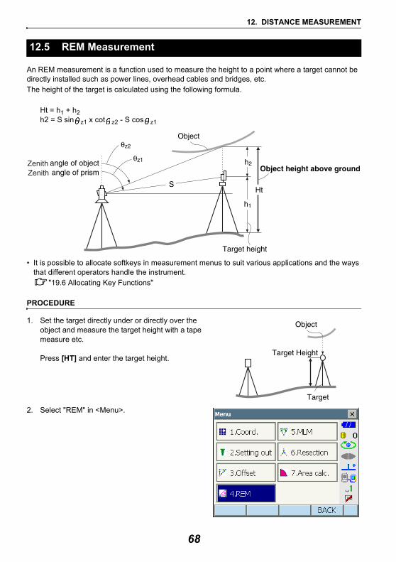
12. DISTANCE MEASUREMENT
An REM measurement is a function used to measure the height to a point where a target cannot be directly installed such as power lines, overhead cables and bridges, etc.The height of the target is calculated using the following formula.
Ht = h1 + h2h2 = S sin z1 x cot z2 - S cos z1
• It is possible to allocate softkeys in measurement menus to suit various applications and the ways that different operators handle the instrument.
"19.6 Allocating Key Functions"
PROCEDURE
1. Set the target directly under or directly over the object and measure the target height with a tape measure etc.
Press [HT] and enter the target height.
2. Select "REM" in <Menu>.
12.5 REM Measurement
ZenithZenith
68
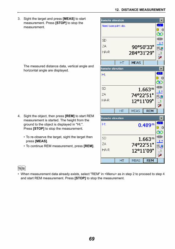
12. DISTANCE MEASUREMENT
3. Sight the target and press [MEAS] to start measurement. Press [STOP] to stop the measurement.
The measured distance data, vertical angle and horizontal angle are displayed.
4. Sight the object, then press [REM] to start REM measurement is started. The height from the ground to the object is displayed in "Ht.". Press [STOP] to stop the measurement.
• To re-observe the target, sight the target then press [MEAS].
• To continue REM measurement, press [REM].
• When measurement data already exists, select "REM" in <Menu> as in step 2 to proceed to step 4 and start REM measurement. Press [STOP] to stop the measurement.
69

13.COORDINATE MEASUREMENT
By performing coordinate measurements it is possible to find the 3-dimensional coordinates of the target based on station point coordinates, instrument height, target height, and azimuth angles of the backsight station which are entered in advance.• It is possible to allocate softkeys in measurement menus to suit various applications and the ways that different operators handle the instrument.
"19.6 Allocating Key Functions"
Before performing coordinate measurement, enter instrument station coordinates and instrument height.
• "Occupy" on the software represents instrument station.
PROCEDURE
1. First measure the instrument height with a tape measure, etc.
2. Select "Coord." in <Menu>.
13.1 Entering Instrument Station Data
70
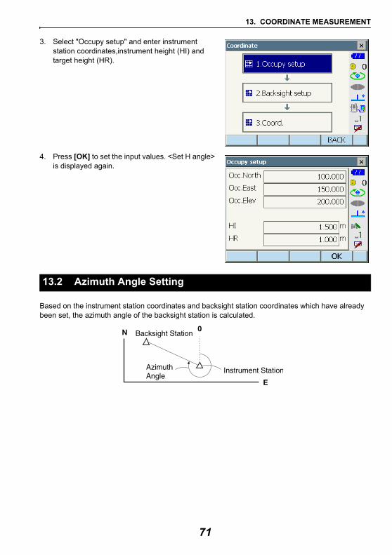
13. COORDINATE MEASUREMENT
3. Select "Occupy setup" and enter instrument station coordinates,instrument height (HI) and target height (HR).
4. Press [OK] to set the input values. <Set H angle> is displayed again.
Based on the instrument station coordinates and backsight station coordinates which have already been set, the azimuth angle of the backsight station is calculated.
13.2 Azimuth Angle Setting
71
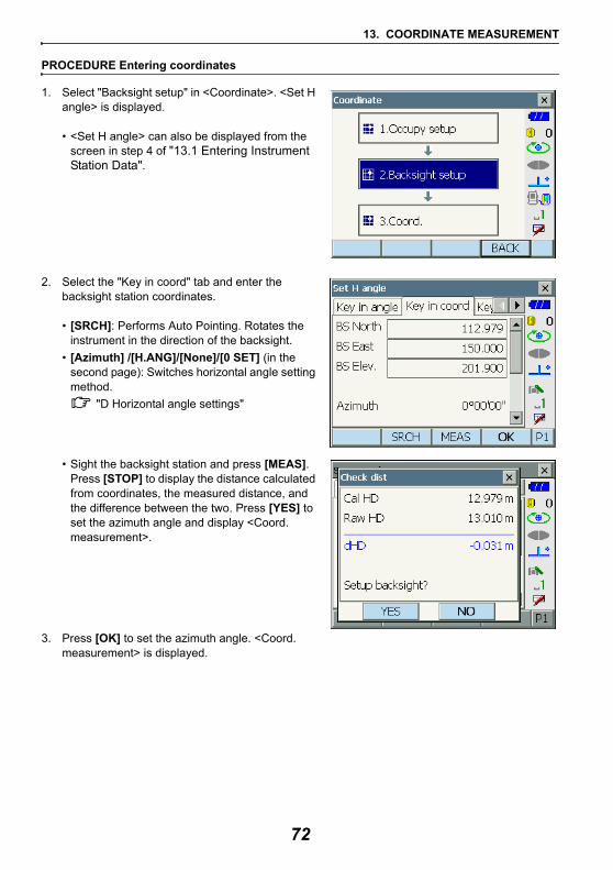
13. COORDINATE MEASUREMENT
PROCEDURE Entering coordinates
1. Select "Backsight setup" in <Coordinate>. <Set H angle> is displayed.
• <Set H angle> can also be displayed from the screen in step 4 of "13.1 Entering Instrument Station Data".
2. Select the "Key in coord" tab and enter the backsight station coordinates.
• [SRCH]: Performs Auto Pointing. Rotates the instrument in the direction of the backsight.
• [Azimuth] /[H.ANG]/[None]/[0 SET] (in the second page): Switches horizontal angle setting method.
"D Horizontal angle settings"
• Sight the backsight station and press [MEAS]. Press [STOP] to display the distance calculated from coordinates, the measured distance, and the difference between the two. Press [YES] to set the azimuth angle and display <Coord. measurement>.
3. Press [OK] to set the azimuth angle. <Coord. measurement> is displayed.
72
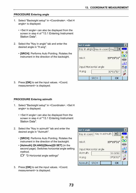
13. COORDINATE MEASUREMENT
PROCEDURE Entering angle
1. Select "Backsight setup" in <Coordinate>. <Set H angle> is displayed.
• <Set H angle> can also be displayed from the screen in step 4 of "13.1 Entering Instrument Station Data".
2. Select the "Key in angle" tab and enter the desired angle in "H.ang".
• [SRCH]: Performs Auto Pointing. Rotates the instrument in the direction of the backsight.
3. Press [OK] to set the input values. <Coord. measurement> is displayed.
PROCEDURE Entering azimuth
1. Select "Backsight setup" in <Coordinate>. <Set H angle> is displayed.
• <Set H angle> can also be displayed from the screen in step 4 of "13.1 Entering Instrument Station Data".
2. Select the "Key in azimuth" tab and enter the desired angle in "Azimuth".
• [SRCH]: Performs Auto Pointing. Rotates the instrument in the direction of the backsight.
• [Azimuth] /[H.ANG]/[None]/[0 SET] (in the second page): Switches horizontal angle setting method.
"D Horizontal angle settings"
3. Press [OK] to set the input values. <Coord. measurement> is displayed.
73
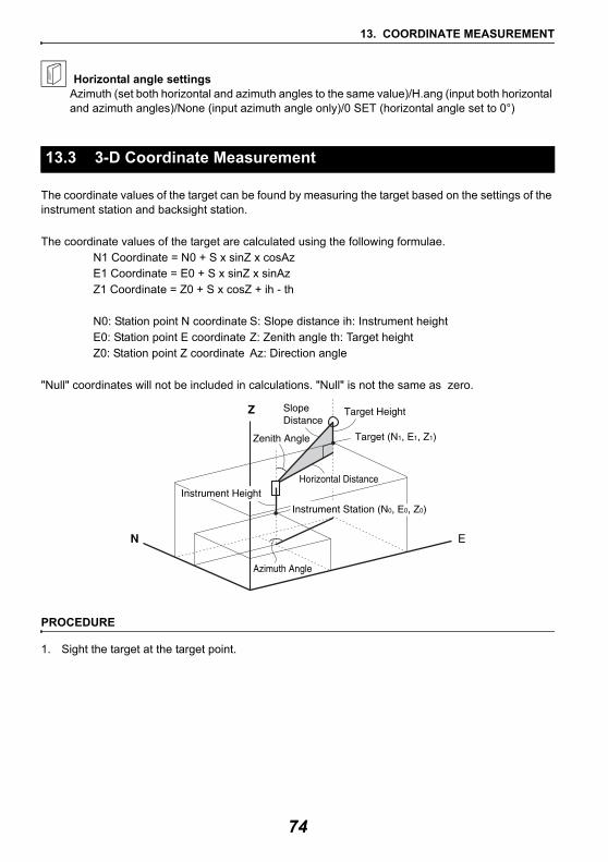
13. COORDINATE MEASUREMENT
Horizontal angle settingsAzimuth (set both horizontal and azimuth angles to the same value)/H.ang (input both horizontal and azimuth angles)/None (input azimuth angle only)/0 SET (horizontal angle set to 0°)
The coordinate values of the target can be found by measuring the target based on the settings of the instrument station and backsight station.
The coordinate values of the target are calculated using the following formulae. N1 Coordinate = N0 + S x sinZ x cosAzE1 Coordinate = E0 + S x sinZ x sinAzZ1 Coordinate = Z0 + S x cosZ + ih - th
N0: Station point N coordinate S: Slope distance ih: Instrument heightE0: Station point E coordinate Z: Zenith angle th: Target heightZ0: Station point Z coordinate Az: Direction angle
"Null" coordinates will not be included in calculations. "Null" is not the same as zero.
PROCEDURE
1. Sight the target at the target point.
13.3 3-D Coordinate Measurement
74
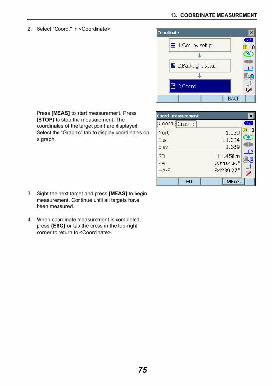
13. COORDINATE MEASUREMENT
2. Select "Coord." in <Coordinate>.
Press [MEAS] to start measurement. Press [STOP] to stop the measurement. The coordinates of the target point are displayed. Select the "Graphic" tab to display coordinates on a graph.
3. Sight the next target and press [MEAS] to begin measurement. Continue until all targets have been measured.
4. When coordinate measurement is completed, press {ESC} or tap the cross in the top-right corner to return to <Coordinate>.
75
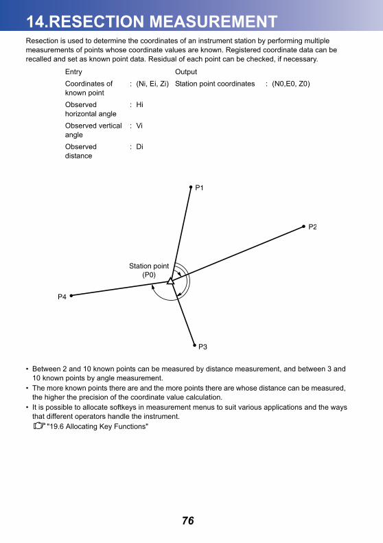
14.RESECTION MEASUREMENT
Resection is used to determine the coordinates of an instrument station by performing multiple measurements of points whose coordinate values are known. Registered coordinate data can be recalled and set as known point data. Residual of each point can be checked, if necessary.• Between 2 and 10 known points can be measured by distance measurement, and between 3 and 10 known points by angle measurement.
• The more known points there are and the more points there are whose distance can be measured, the higher the precision of the coordinate value calculation.
• It is possible to allocate softkeys in measurement menus to suit various applications and the ways that different operators handle the instrument.
"19.6 Allocating Key Functions"
Entry OutputCoordinates of known point
: (Ni, Ei, Zi) Station point coordinates : (N0,E0, Z0)
Observed horizontal angle
: Hi
Observed vertical angle
: Vi
Observed distance
: Di
76
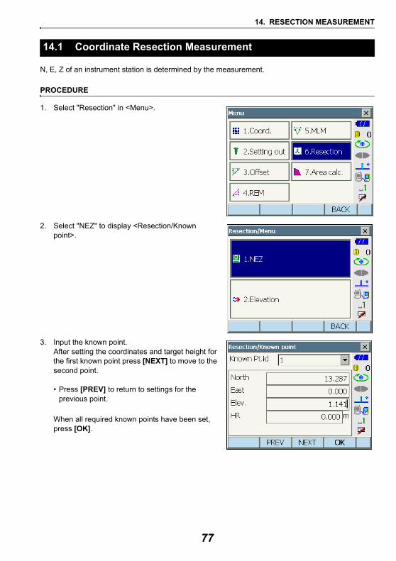
14. RESECTION MEASUREMENT
N, E, Z of an instrument station is determined by the measurement.
PROCEDURE
1. Select "Resection" in <Menu>.
2. Select "NEZ" to display <Resection/Known point>.
3. Input the known point. After setting the coordinates and target height for the first known point press [NEXT] to move to the second point.
• Press [PREV] to return to settings for the previous point.
When all required known points have been set, press [OK].
14.1 Coordinate Resection Measurement
77
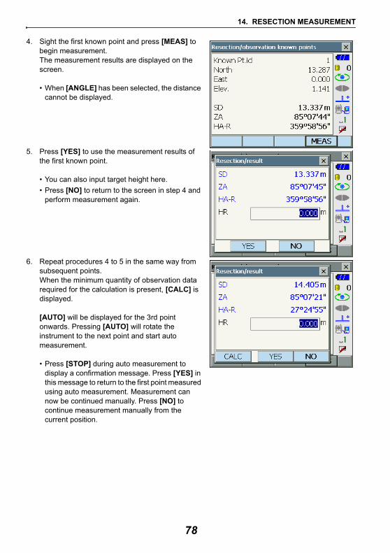
14. RESECTION MEASUREMENT
4. Sight the first known point and press [MEAS] to begin measurement.The measurement results are displayed on the screen.
• When [ANGLE] has been selected, the distance cannot be displayed.
5. Press [YES] to use the measurement results of the first known point.
• You can also input target height here.• Press [NO] to return to the screen in step 4 and
perform measurement again.
6. Repeat procedures 4 to 5 in the same way from subsequent points.When the minimum quantity of observation data required for the calculation is present, [CALC] is displayed.
[AUTO] will be displayed for the 3rd point onwards. Pressing [AUTO] will rotate the instrument to the next point and start auto measurement.
• Press [STOP] during auto measurement to display a confirmation message. Press [YES] in this message to return to the first point measured using auto measurement. Measurement can now be continued manually. Press [NO] to continue measurement manually from the current position.
78
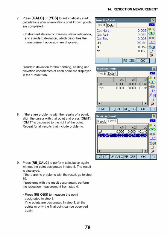
14. RESECTION MEASUREMENT
7. Press [CALC] or [YES] to automatically start calculations after observations of all known points are completed.
• Instrument station coordinates, station elevation, and standard deviation, which describes the measurement accuracy, are displayed.
Standard deviation for the northing, easting and elevation coordinates of each point are displayed in the "Detail" tab.
8. If there are problems with the results of a point, align the cursor with that point and press [OMIT]. “OMIT” is displayed to the right of the point. Repeat for all results that include problems.
9. Press [RE_CALC] to perform calculation again without the point designated in step 8. The result is displayed.If there are no problems with the result, go to step 10.If problems with the result occur again, perform the resection measurement from step 4.
• Press [RE OBS] to measure the point designated in step 8. If no points are designated in step 8, all the points or only the final point can be observed again.
2nd
79
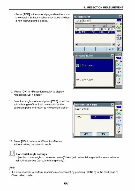
14. RESECTION MEASUREMENT
• Press [ADD] in the second page when there is a known point that has not been observed or when a new known point is added.
10. Press [OK] in <Resection/result> to display <Resection/Set h angle>.
11. Select an angle mode and press [YES] to set the azimuth angle of the first known point as the backsight point and return to <Resection/Menu>.
12. Press [NO] to return to <Resection/Menu> without setting the azimuth angle.
Horizontal angle settingsH (set horizontal angle to measured value)/H=Az (set horizontal angle to the same value as azimuth angle)/Az (set azimuth angle only)
• It is also possible to perform resection measurement by pressing [RESEC] in the third page of Observation mode.
80
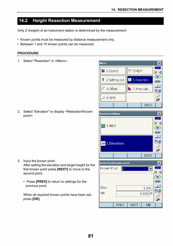
14. RESECTION MEASUREMENT
Only Z (height) of an instrument station is determined by the measurement.
• Known points must be measured by distance measurement only.• Between 1 and 10 known points can be measured.
PROCEDURE
1. Select "Resection" in <Menu>.
2. Select "Elevation" to display <Resection/Known point>.
3. Input the known point.After setting the elevation and target height for the first known point press [NEXT] to move to the second point.
• Press [PREV] to return to settings for the previous point.
When all required known points have been set, press [OK].
14.2 Height Resection Measurement
81
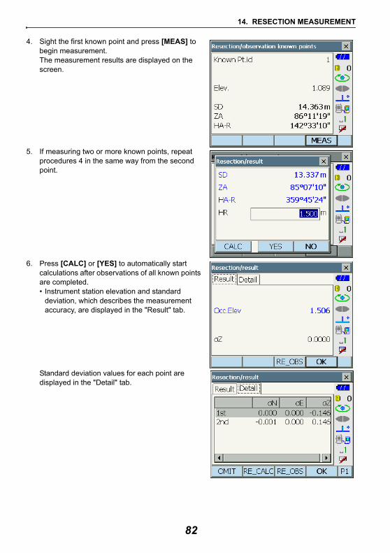
14. RESECTION MEASUREMENT
4. Sight the first known point and press [MEAS] to begin measurement.The measurement results are displayed on the screen.
5. If measuring two or more known points, repeat procedures 4 in the same way from the second point.
6. Press [CALC] or [YES] to automatically start calculations after observations of all known points are completed.• Instrument station elevation and standard
deviation, which describes the measurement accuracy, are displayed in the "Result" tab.
Standard deviation values for each point are displayed in the "Detail" tab.
82
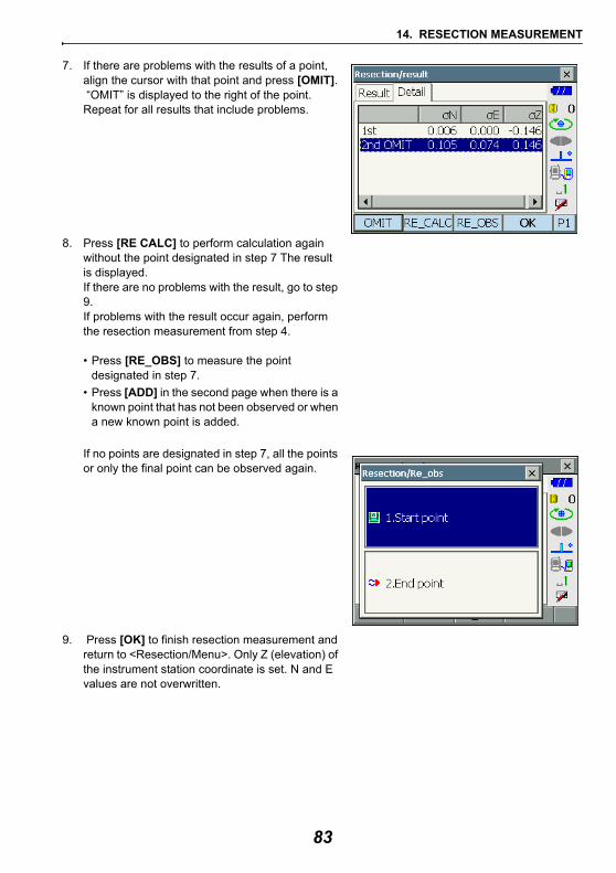
14. RESECTION MEASUREMENT
7. If there are problems with the results of a point, align the cursor with that point and press [OMIT]. “OMIT” is displayed to the right of the point. Repeat for all results that include problems.
8. Press [RE CALC] to perform calculation again without the point designated in step 7 The result is displayed.If there are no problems with the result, go to step 9.If problems with the result occur again, perform the resection measurement from step 4.
• Press [RE_OBS] to measure the point designated in step 7.
• Press [ADD] in the second page when there is a known point that has not been observed or when a new known point is added.
If no points are designated in step 7, all the points or only the final point can be observed again.
9. Press [OK] to finish resection measurement and return to <Resection/Menu>. Only Z (elevation) of the instrument station coordinate is set. N and E values are not overwritten.
83
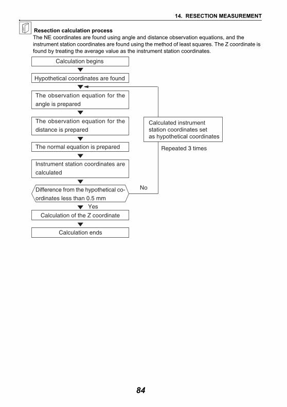
14. RESECTION MEASUREMENT
Resection calculation processThe NE coordinates are found using angle and distance observation equations, and the instrument station coordinates are found using the method of least squares. The Z coordinate is found by treating the average value as the instrument station coordinates.
Calculated instrumentstation coordinates set as hypothetical coordinates
84
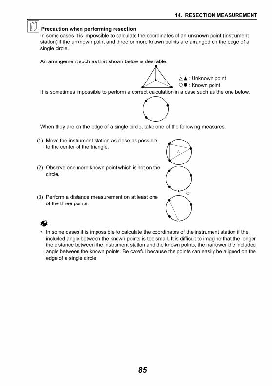
14. RESECTION MEASUREMENT
Precaution when performing resectionIn some cases it is impossible to calculate the coordinates of an unknown point (instrument station) if the unknown point and three or more known points are arranged on the edge of a single circle.
An arrangement such as that shown below is desirable.
It is sometimes impossible to perform a correct calculation in a case such as the one below.
When they are on the edge of a single circle, take one of the following measures.
(1) Move the instrument station as close as possible to the center of the triangle.
(2) Observe one more known point which is not on the circle.
(3) Perform a distance measurement on at least one of the three points.
• In some cases it is impossible to calculate the coordinates of the instrument station if the included angle between the known points is too small. It is difficult to imagine that the longer the distance between the instrument station and the known points, the narrower the included angle between the known points. Be careful because the points can easily be aligned on the edge of a single circle.
: Unknown point : Known point
85
15.SETTING-OUT MEASUREMENT
Setting-out measurement is used to set out the required point. The difference between the previously input data to the instrument (the setting-out data) and the measured value can be displayed by measuring the horizontal angle, distance or coordinates of the sighted point.The horizontal angle difference distance difference, and coordinate difference are calculated and displayed using the following formulae.Horizontal differenceDisplayed value (angle) = Horizontal angle of setting-out data - measured horizontal angle Displayed value (distance) = measured horizontal distance x tan (horizontal angle of setting out data
- measured horizontal angle)
Slope distance difference Displayed value (slope distance) * = measured slope distance - slope distance setting-out data* Horizontal distance or height difference can be input in the above formula.
Coordinate differenceDisplayed value (coordinates)* measured N setting-out coordinates - N coordinates of setting-out data * E or Z coordinates can be input in the above formula
Height difference (REM setting out measurement)Displayed value (height) = measured REM data - REM data of setting out data
• Setting out data can be input in various modes: slope distance, horizontal distance, height difference, coordinates and REM measurement.
• It is possible to allocate softkeys in the Setting-out measurement menu to suit various applications and the ways that different operators handle the instrument.
"19.6 Allocating Key Functions"
When the guide light is set to ON, the flashing speed of the light indicates the status of the instrument and can be known when the user is located at a distance from the instrument. Also, the flashing colors relative to the target indicate the direction of the instrument and allow the user to reposition the target.
Turning the Guide light ON/OFF: "5.1 Basic Key Operation"
• The pattern of the guide light can be changed."19.2 Instrument Configuration"
15.1 Using the Guide Light in Setting-out Measurement
86
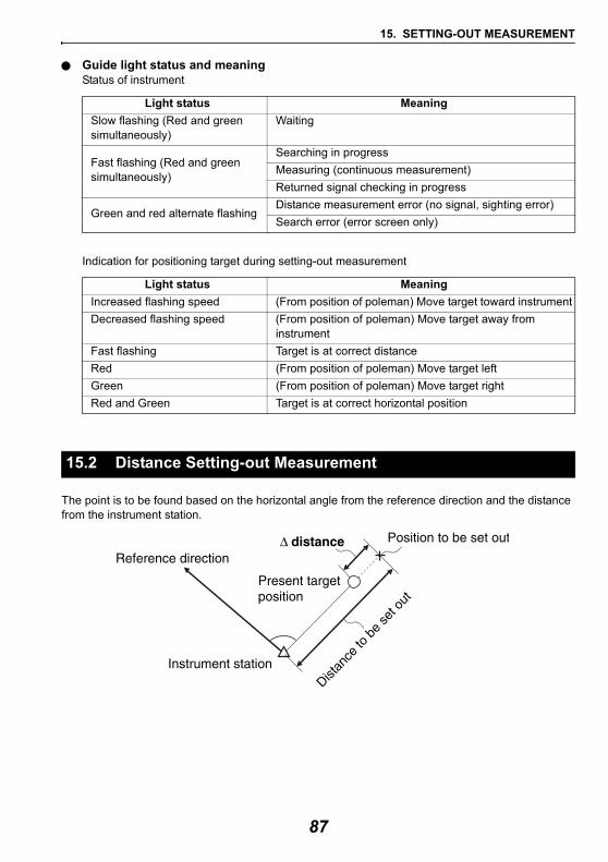
15. SETTING-OUT MEASUREMENT
Guide light status and meaningStatus of instrument
Indication for positioning target during setting-out measurement
The point is to be found based on the horizontal angle from the reference direction and the distance from the instrument station.
Light status MeaningSlow flashing (Red and green simultaneously)
Waiting
Fast flashing (Red and green simultaneously)
Searching in progressMeasuring (continuous measurement)Returned signal checking in progress
Green and red alternate flashingDistance measurement error (no signal, sighting error)Search error (error screen only)
Light status MeaningIncreased flashing speed (From position of poleman) Move target toward instrumentDecreased flashing speed (From position of poleman) Move target away from
instrumentFast flashing Target is at correct distanceRed (From position of poleman) Move target left Green (From position of poleman) Move target rightRed and Green Target is at correct horizontal position
15.2 Distance Setting-out Measurement
87
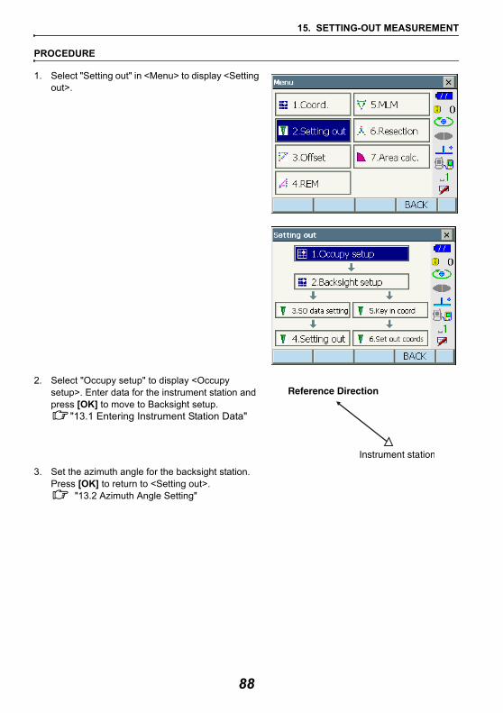
15. SETTING-OUT MEASUREMENT
PROCEDURE
1. Select "Setting out" in <Menu> to display <Setting out>.
2. Select "Occupy setup" to display <Occupy setup>. Enter data for the instrument station and press [OK] to move to Backsight setup.
"13.1 Entering Instrument Station Data"
3. Set the azimuth angle for the backsight station. Press [OK] to return to <Setting out>.
"13.2 Azimuth Angle Setting"
88
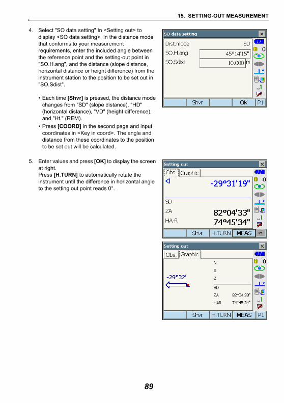
15. SETTING-OUT MEASUREMENT
4. Select "SO data setting" In <Setting out> to display <SO data setting>. In the distance mode that conforms to your measurement requirements, enter the included angle between the reference point and the setting-out point in "SO.H.ang", and the distance (slope distance, horizontal distance or height difference) from the instrument station to the position to be set out in "SO.Sdist".
• Each time [Shvr] is pressed, the distance mode changes from "SD" (slope distance), "HD" (horizontal distance), "VD" (height difference), and "Ht." (REM).
• Press [COORD] in the second page and input coordinates in <Key in coord>. The angle and distance from these coordinates to the position to be set out will be calculated.
5. Enter values and press [OK] to display the screen at right. Press [H.TURN] to automatically rotate the instrument until the difference in horizontal angle to the setting out point reads 0°.
P1
89
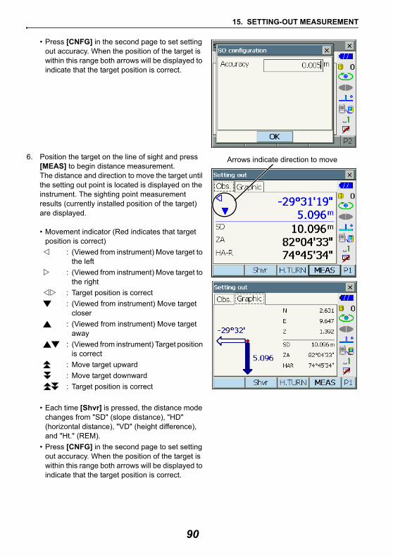
15. SETTING-OUT MEASUREMENT
• Press [CNFG] in the second page to set setting out accuracy. When the position of the target is within this range both arrows will be displayed to indicate that the target position is correct.
6. Position the target on the line of sight and press [MEAS] to begin distance measurement.The distance and direction to move the target until the setting out point is located is displayed on the instrument. The sighting point measurement results (currently installed position of the target) are displayed.
• Movement indicator (Red indicates that target position is correct)
: (Viewed from instrument) Move target to the left
: (Viewed from instrument) Move target to the right
: Target position is correct: (Viewed from instrument) Move target
closer: (Viewed from instrument) Move target
away: (Viewed from instrument) Target position
is correct: Move target upward: Move target downward: Target position is correct
• Each time [Shvr] is pressed, the distance mode changes from "SD" (slope distance), "HD" (horizontal distance), "VD" (height difference), and "Ht." (REM).
• Press [CNFG] in the second page to set setting out accuracy. When the position of the target is within this range both arrows will be displayed to indicate that the target position is correct.
Arrows indicate direction to move
90
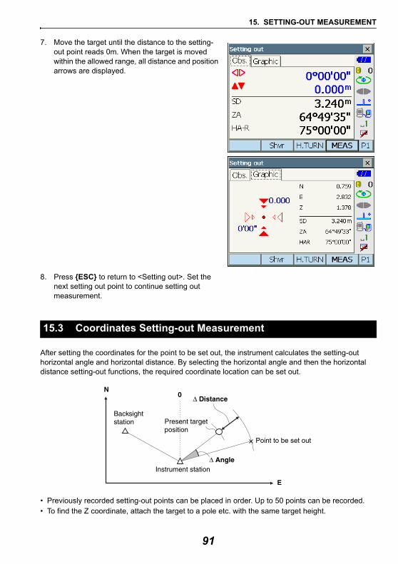
15. SETTING-OUT MEASUREMENT
7. Move the target until the distance to the setting-out point reads 0m. When the target is moved within the allowed range, all distance and position arrows are displayed.
8. Press {ESC} to return to <Setting out>. Set the next setting out point to continue setting out measurement.
After setting the coordinates for the point to be set out, the instrument calculates the setting-out horizontal angle and horizontal distance. By selecting the horizontal angle and then the horizontal distance setting-out functions, the required coordinate location can be set out.
• Previously recorded setting-out points can be placed in order. Up to 50 points can be recorded.• To find the Z coordinate, attach the target to a pole etc. with the same target height.
15.3 Coordinates Setting-out Measurement
91
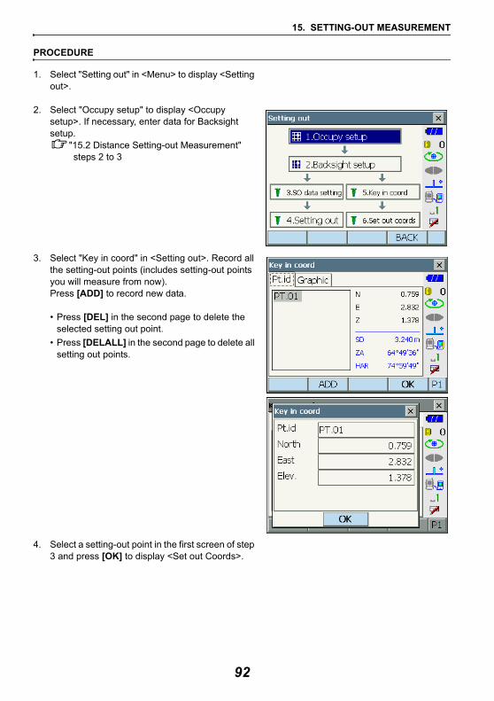
15. SETTING-OUT MEASUREMENT
PROCEDURE
1. Select "Setting out" in <Menu> to display <Setting out>.
2. Select "Occupy setup" to display <Occupy setup>. If necessary, enter data for Backsight setup.
"15.2 Distance Setting-out Measurement" steps 2 to 3
3. Select "Key in coord" in <Setting out>. Record all the setting-out points (includes setting-out points you will measure from now). Press [ADD] to record new data.
• Press [DEL] in the second page to delete the selected setting out point.
• Press [DELALL] in the second page to delete all setting out points.
4. Select a setting-out point in the first screen of step 3 and press [OK] to display <Set out Coords>.
92
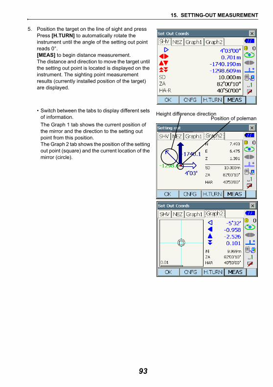
15. SETTING-OUT MEASUREMENT
5. Position the target on the line of sight and press Press [H.TURN] to automatically rotate the instrument until the angle of the setting out point reads 0°.[MEAS] to begin distance measurement.The distance and direction to move the target until the setting out point is located is displayed on the instrument. The sighting point measurement results (currently installed position of the target) are displayed.
• Switch between the tabs to display different sets of information.The Graph 1 tab shows the current position of the mirror and the direction to the setting out point from this position.The Graph 2 tab shows the position of the setting out point (square) and the current location of the mirror (circle).
Height difference directionPosition of poleman
93
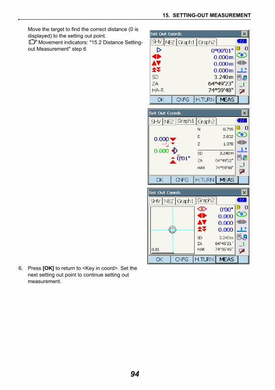
15. SETTING-OUT MEASUREMENT
Move the target to find the correct distance (0 is displayed) to the setting out point.
Movement indicators: "15.2 Distance Setting-out Measurement" step 6
6. Press [OK] to return to <Key in coord>. Set the next setting out point to continue setting out measurement.
94
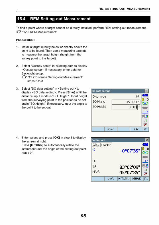
15. SETTING-OUT MEASUREMENT
To find a point where a target cannot be directly installed, perform REM setting-out measurement. "12.5 REM Measurement"
PROCEDURE
1. Install a target directly below or directly above the point to be found. Then use a measuring tape etc. to measure the target height (height from the survey point to the target).
2. Select "Occupy setup" in <Setting out> to display <Occupy setup>. If necessary, enter data for Backsight setup.
"15.2 Distance Setting-out Measurement" steps 2 to 3
3. Select "SO data setting" In <Setting out> to display <SO data setting>. Press [Shvr] until the distance input mode is "SO.Height.". Input height from the surveying point to the position to be set out in "SO.Height". If necessary, input the angle to the point to be set out.
4. Enter values and press [OK] in step 3 to display the screen at right. Press [H.TURN] to automatically rotate the instrument until the angle of the setting out point reads 0°.
15.4 REM Setting-out Measurement
95
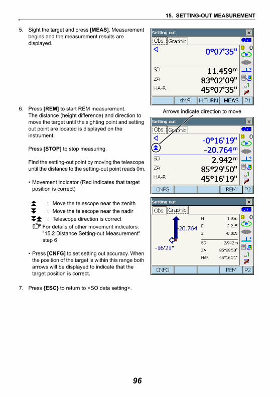
15. SETTING-OUT MEASUREMENT
5. Sight the target and press [MEAS]. Measurement begins and the measurement results are displayed.
6. Press [REM] to start REM measurement.The distance (height difference) and direction to move the target until the sighting point and setting out point are located is displayed on the instrument.
Press [STOP] to stop measuring.
Find the setting-out point by moving the telescope until the distance to the setting-out point reads 0m.
• Movement indicator (Red indicates that target position is correct)
: Move the telescope near the zenith: Move the telescope near the nadir : Telescope direction is correct
For details of other movement indicators: "15.2 Distance Setting-out Measurement" step 6
• Press [CNFG] to set setting out accuracy. When the position of the target is within this range both arrows will be displayed to indicate that the target position is correct.
7. Press {ESC} to return to <SO data setting>.
Arrows indicate direction to move
96
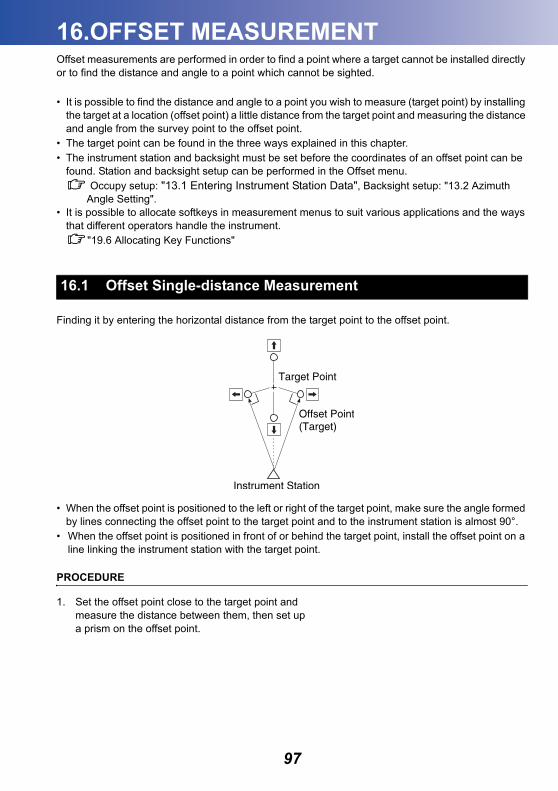
16.OFFSET MEASUREMENT
Offset measurements are performed in order to find a point where a target cannot be installed directly or to find the distance and angle to a point which cannot be sighted.• It is possible to find the distance and angle to a point you wish to measure (target point) by installing the target at a location (offset point) a little distance from the target point and measuring the distance and angle from the survey point to the offset point.
• The target point can be found in the three ways explained in this chapter.• The instrument station and backsight must be set before the coordinates of an offset point can be
found. Station and backsight setup can be performed in the Offset menu. Occupy setup: "13.1 Entering Instrument Station Data", Backsight setup: "13.2 Azimuth Angle Setting".
• It is possible to allocate softkeys in measurement menus to suit various applications and the ways that different operators handle the instrument.
"19.6 Allocating Key Functions"
Finding it by entering the horizontal distance from the target point to the offset point.
• When the offset point is positioned to the left or right of the target point, make sure the angle formed by lines connecting the offset point to the target point and to the instrument station is almost 90°.
• When the offset point is positioned in front of or behind the target point, install the offset point on a line linking the instrument station with the target point.
PROCEDURE
1. Set the offset point close to the target point and measure the distance between them, then set up a prism on the offset point.
16.1 Offset Single-distance Measurement
97
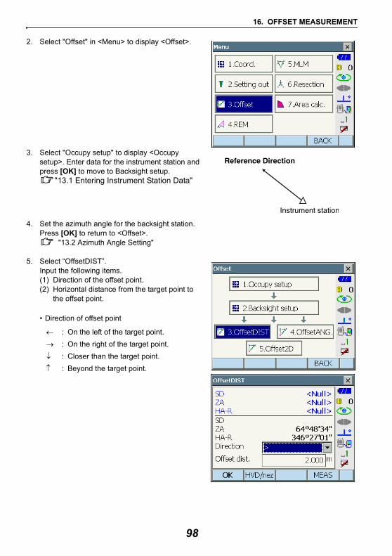
16. OFFSET MEASUREMENT
2. Select "Offset" in <Menu> to display <Offset>.
3. Select "Occupy setup" to display <Occupy setup>. Enter data for the instrument station and press [OK] to move to Backsight setup.
"13.1 Entering Instrument Station Data"
4. Set the azimuth angle for the backsight station. Press [OK] to return to <Offset>.
"13.2 Azimuth Angle Setting"
5. Select “OffsetDIST”.Input the following items. (1) Direction of the offset point.(2) Horizontal distance from the target point to
the offset point.
• Direction of offset point
← : On the left of the target point.→ : On the right of the target point.↓ : Closer than the target point.↑ : Beyond the target point.
98
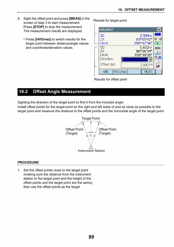
16. OFFSET MEASUREMENT
6. Sight the offset point and press [MEAS] in the screen of step 3 to start measurement. Press [STOP] to stop the measurement.The measurement results are displayed.
• Press [HVD/nez] to switch results for the target point between distance/angle values and coordinate/elevation values.
Sighting the direction of the target point to find it from the included angle.Install offset points for the target point on the right and left sides of and as close as possible to the target point and measure the distance to the offset points and the horizontal angle of the target point.
PROCEDURE
1. Set the offset points close to the target point (making sure the distance from the instrument station to the target point and the height of the offset points and the target point are the same), then use the offset points as the target.
16.2 Offset Angle Measurement
Results for target point
Results for offset point
99
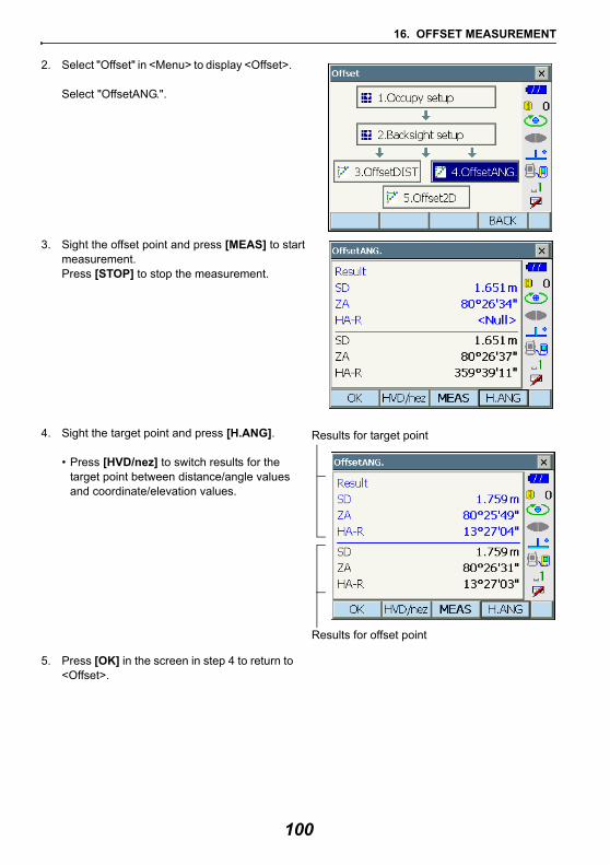
16. OFFSET MEASUREMENT
2. Select "Offset" in <Menu> to display <Offset>.
Select "OffsetANG.".
3. Sight the offset point and press [MEAS] to start measurement. Press [STOP] to stop the measurement.
4. Sight the target point and press [H.ANG].
• Press [HVD/nez] to switch results for the target point between distance/angle values and coordinate/elevation values.
5. Press [OK] in the screen in step 4 to return to <Offset>.
Results for offset point
Results for target point
100
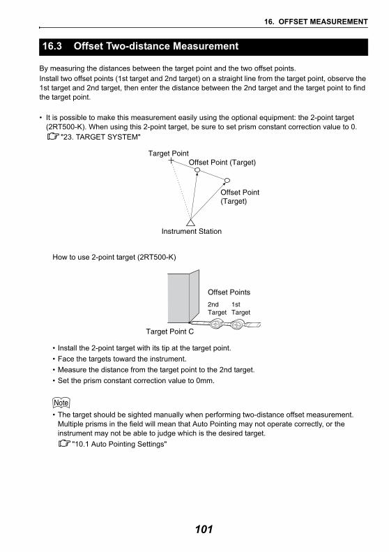
16. OFFSET MEASUREMENT
By measuring the distances between the target point and the two offset points.Install two offset points (1st target and 2nd target) on a straight line from the target point, observe the 1st target and 2nd target, then enter the distance between the 2nd target and the target point to find the target point.
• It is possible to make this measurement easily using the optional equipment: the 2-point target (2RT500-K). When using this 2-point target, be sure to set prism constant correction value to 0.
"23. TARGET SYSTEM"
How to use 2-point target (2RT500-K)
• Install the 2-point target with its tip at the target point.• Face the targets toward the instrument.• Measure the distance from the target point to the 2nd target.• Set the prism constant correction value to 0mm.
• The target should be sighted manually when performing two-distance offset measurement. Multiple prisms in the field will mean that Auto Pointing may not operate correctly, or the instrument may not be able to judge which is the desired target.
"10.1 Auto Pointing Settings"
16.3 Offset Two-distance Measurement
101
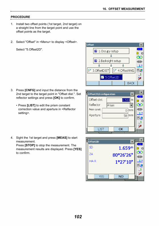
16. OFFSET MEASUREMENT
PROCEDURE
1. Install two offset points (1st target, 2nd target) on a straight line from the target point and use the offset points as the target.
2. Select "Offset" in <Menu> to display <Offset>.
Select "5.Offset2D".
3. Press [CNFG] and input the distance from the 2nd target to the target point in "Offset dist.". Set reflector settings and press [OK] to confirm.
• Press [LIST] to edit the prism constant correction value and aperture in <Reflector setting>.
4. Sight the 1st target and press [MEAS] to start measurement. Press [STOP] to stop the measurement. The measurement results are displayed. Press [YES] to confirm.
102
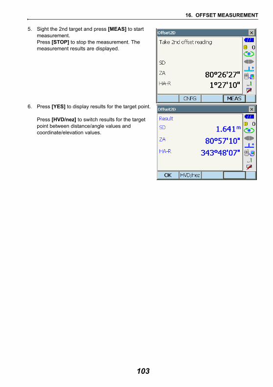
16. OFFSET MEASUREMENT
5. Sight the 2nd target and press [MEAS] to start measurement.Press [STOP] to stop the measurement. The measurement results are displayed.
6. Press [YES] to display results for the target point.
Press [HVD/nez] to switch results for the target point between distance/angle values and coordinate/elevation values.
103
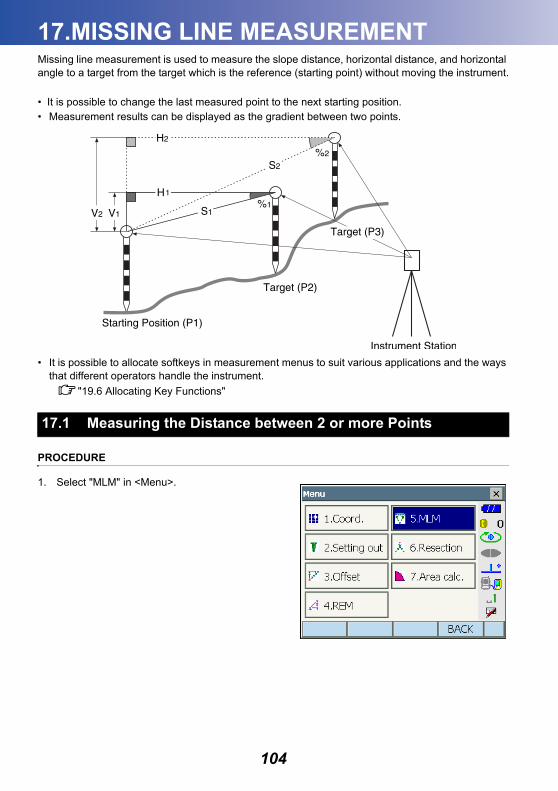
17.MISSING LINE MEASUREMENT
Missing line measurement is used to measure the slope distance, horizontal distance, and horizontal angle to a target from the target which is the reference (starting point) without moving the instrument.• It is possible to change the last measured point to the next starting position.• Measurement results can be displayed as the gradient between two points.
• It is possible to allocate softkeys in measurement menus to suit various applications and the ways that different operators handle the instrument.
"19.6 Allocating Key Functions"
PROCEDURE
1. Select "MLM" in <Menu>.
17.1 Measuring the Distance between 2 or more Points
104
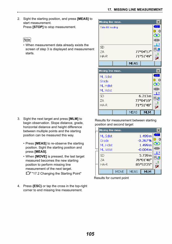
17. MISSING LINE MEASUREMENT
2. Sight the starting position, and press [MEAS] to start measurement. Press [STOP] to stop measurement.
• When measurement data already exists the screen of step 3 is displayed and measurement starts.
3. Sight the next target and press [MLM] to begin observation. Slope distance, grade, horizontal distance and height difference between multiple points and the starting position can be measured this way.
• Press [MEAS] to re-observe the starting position. Sight the starting position and press [MEAS].
• When [MOVE] is pressed, the last target measured becomes the new starting position to perform missing line measurement of the next target.
"17.2 Changing the Starting Point"
4. Press {ESC} or tap the cross in the top-right corner to end missing line measurement.
Results for current point
Results for measurement between starting position and second target
105
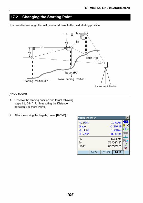
17. MISSING LINE MEASUREMENT
It is possible to change the last measured point to the next starting position.
PROCEDURE
1. Observe the starting position and target following steps 1 to 3 in "17.1 Measuring the Distance between 2 or more Points".
2. After measuring the targets, press [MOVE].
17.2 Changing the Starting Point
106
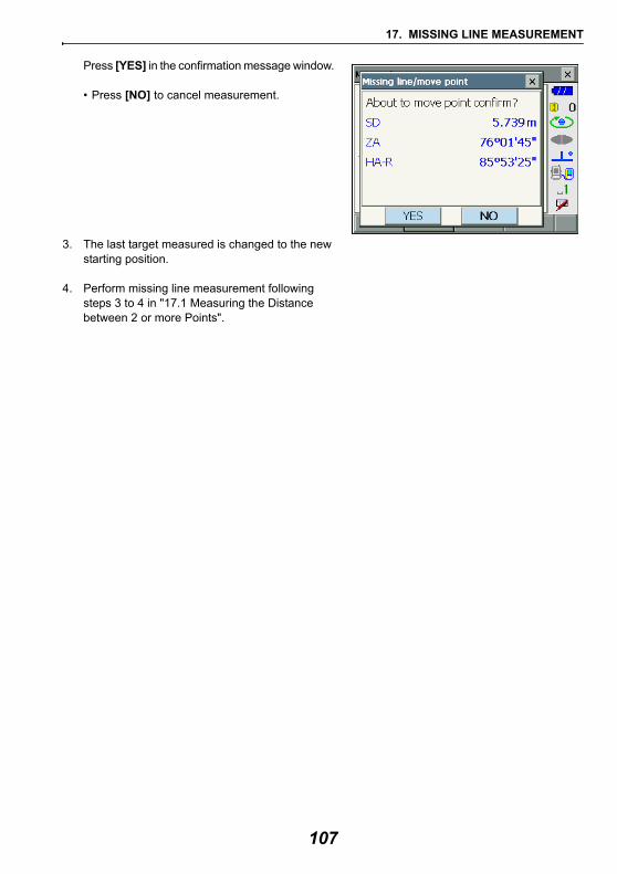
17. MISSING LINE MEASUREMENT
Press [YES] in the confirmation message window.
• Press [NO] to cancel measurement.
3. The last target measured is changed to the new starting position.
4. Perform missing line measurement following steps 3 to 4 in "17.1 Measuring the Distance between 2 or more Points".
107
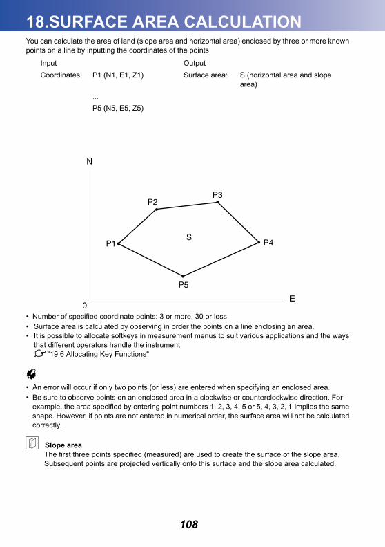
18.SURFACE AREA CALCULATION
You can calculate the area of land (slope area and horizontal area) enclosed by three or more known points on a line by inputting the coordinates of the points• Number of specified coordinate points: 3 or more, 30 or less• Surface area is calculated by observing in order the points on a line enclosing an area.• It is possible to allocate softkeys in measurement menus to suit various applications and the ways
that different operators handle the instrument."19.6 Allocating Key Functions"
• An error will occur if only two points (or less) are entered when specifying an enclosed area.• Be sure to observe points on an enclosed area in a clockwise or counterclockwise direction. For
example, the area specified by entering point numbers 1, 2, 3, 4, 5 or 5, 4, 3, 2, 1 implies the same shape. However, if points are not entered in numerical order, the surface area will not be calculated correctly.
Slope areaThe first three points specified (measured) are used to create the surface of the slope area. Subsequent points are projected vertically onto this surface and the slope area calculated.
Input OutputCoordinates: P1 (N1, E1, Z1) Surface area: S (horizontal area and slope
area) ...P5 (N5, E5, Z5)
108
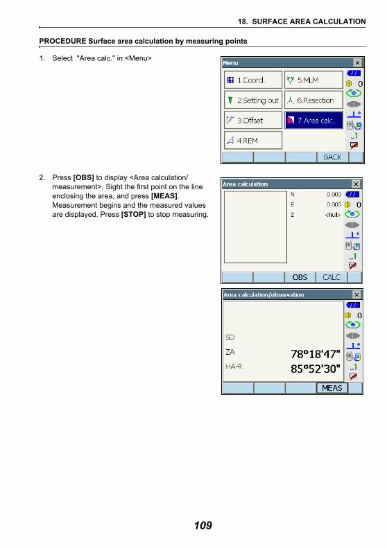
18. SURFACE AREA CALCULATION
PROCEDURE Surface area calculation by measuring points
1. Select "Area calc." in <Menu>
2. Press [OBS] to display <Area calculation/measurement>. Sight the first point on the line enclosing the area, and press [MEAS]. Measurement begins and the measured values are displayed. Press [STOP] to stop measuring.
109
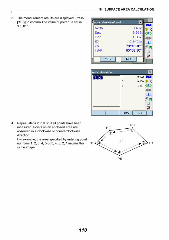
18. SURFACE AREA CALCULATION
3. The measurement results are displayed. Press [YES] to confirm.The value of point 1 is set in "Pt_01".
4. Repeat steps 2 to 3 until all points have been measured. Points on an enclosed area are observed in a clockwise or counterclockwise direction.For example, the area specified by entering point numbers 1, 2, 3, 4, 5 or 5, 4, 3, 2, 1 implies the same shape.
110
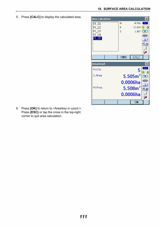
18. SURFACE AREA CALCULATION
5. Press [CALC] to display the calculated area.
6. Press [OK] to return to <Area/key in coord.>. Press {ESC} or tap the cross in the top-right corner to quit area calculation.
111
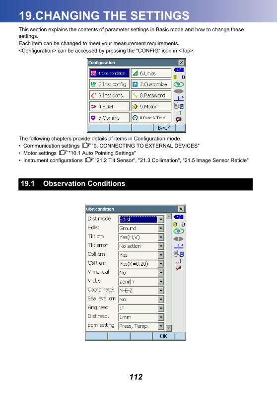
19.CHANGING THE SETTINGS
This section explains the contents of parameter settings in Basic mode and how to change these settings.Each item can be changed to meet your measurement requirements.<Configuration> can be accessed by pressing the "CONFIG" icon in <Top>.The following chapters provide details of items in Configuration mode.• Communication settings "9. CONNECTING TO EXTERNAL DEVICES"• Motor settings "10.1 Auto Pointing Settings"• Instrument configurations "21.2 Tilt Sensor", "21.3 Collimation", "21.5 Image Sensor Reticle"
19.1 Observation Conditions
112
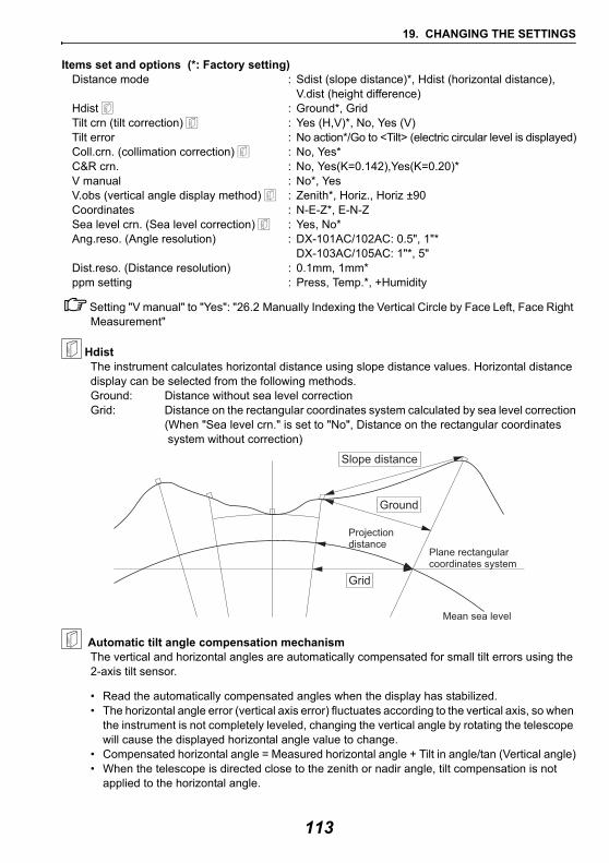
19. CHANGING THE SETTINGS
Items set and options (*: Factory setting)Distance mode : Sdist (slope distance)*, Hdist (horizontal distance),
V.dist (height difference)Hdist : Ground*, GridTilt crn (tilt correction) : Yes (H,V)*, No, Yes (V)Tilt error : No action*/Go to <Tilt> (electric circular level is displayed)Coll.crn. (collimation correction) : No, Yes*C&R crn. : No, Yes(K=0.142),Yes(K=0.20)*V manual : No*, YesV.obs (vertical angle display method) : Zenith*, Horiz., Horiz ±90Coordinates : N-E-Z*, E-N-ZSea level crn. (Sea level correction) : Yes, No*Ang.reso. (Angle resolution) : DX-101AC/102AC: 0.5", 1"*
DX-103AC/105AC: 1"*, 5"Dist.reso. (Distance resolution) : 0.1mm, 1mm*ppm setting : Press, Temp.*, +Humidity
Setting "V manual" to "Yes": "26.2 Manually Indexing the Vertical Circle by Face Left, Face Right Measurement"
HdistThe instrument calculates horizontal distance using slope distance values. Horizontal distance display can be selected from the following methods.Ground: Distance without sea level correctionGrid: Distance on the rectangular coordinates system calculated by sea level correction
(When "Sea level crn." is set to "No", Distance on the rectangular coordinates system without correction)
Automatic tilt angle compensation mechanismThe vertical and horizontal angles are automatically compensated for small tilt errors using the 2-axis tilt sensor.
• Read the automatically compensated angles when the display has stabilized. • The horizontal angle error (vertical axis error) fluctuates according to the vertical axis, so when
the instrument is not completely leveled, changing the vertical angle by rotating the telescope will cause the displayed horizontal angle value to change.
• Compensated horizontal angle = Measured horizontal angle + Tilt in angle/tan (Vertical angle)• When the telescope is directed close to the zenith or nadir angle, tilt compensation is not
applied to the horizontal angle.
Mean sea level
Plane rectangularcoordinates system
Projectiondistance
Ground
Grid
Slope distance
113
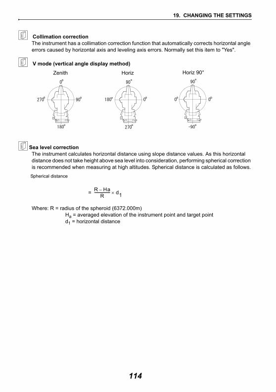
19. CHANGING THE SETTINGS
Collimation correctionThe instrument has a collimation correction function that automatically corrects horizontal angle errors caused by horizontal axis and leveling axis errors. Normally set this item to "Yes".
V mode (vertical angle display method)
Sea level correctionThe instrument calculates horizontal distance using slope distance values. As this horizontal distance does not take height above sea level into consideration, performing spherical correction is recommended when measuring at high altitudes. Spherical distance is calculated as follows.
Where: R = radius of the spheroid (6372.000m)Ha = averaged elevation of the instrument point and target pointd1 = horizontal distance
Zenith Horiz Horiz 90°
Spherical distance
R Ha–R
------------------ d1×=
114
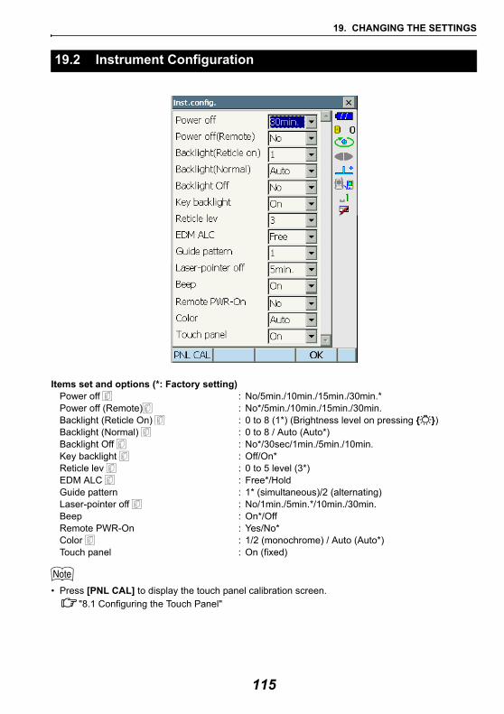
19. CHANGING THE SETTINGS
Items set and options (*: Factory setting)Power off : No/5min./10min./15min./30min.*Power off (Remote) : No*/5min./10min./15min./30min.Backlight (Reticle On) : 0 to 8 (1*) (Brightness level on pressing { })Backlight (Normal) : 0 to 8 / Auto (Auto*)Backlight Off : No*/30sec/1min./5min./10min.Key backlight : Off/On*Reticle lev : 0 to 5 level (3*)EDM ALC : Free*/HoldGuide pattern : 1* (simultaneous)/2 (alternating)Laser-pointer off : No/1min./5min.*/10min./30min.Beep : On*/OffRemote PWR-On : Yes/No*Color : 1/2 (monochrome) / Auto (Auto*)Touch panel : On (fixed)
• Press [PNL CAL] to display the touch panel calibration screen."8.1 Configuring the Touch Panel"
19.2 Instrument Configuration
115
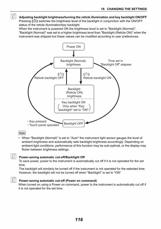
19. CHANGING THE SETTINGS
Adjusting backlight brightness/turning the reticle illumination and key backlight ON/OFFPressing { } switches the brightness level of the backlight in conjunction with the ON/OFF status of the reticle illumination/key backlight. When the instrument is powered ON the brightness level is set to "Backlight (Normal)". "Backlight (Normal)" was set to a higher brightness level than "Backlight (Reticle ON)" when the instrument was shipped but these values can be modified according to user preferences.
• When "Backlight (Normal)" is set to "Auto" the instrument light sensor gauges the level of ambient brightness and automatically sets backlight brightness accordingly. Depending on ambient light conditions, performance of this function may be sub-optimal, or the display may flicker between brightness settings.
Power-saving automatic cut-off/Backlight OffTo save power, power to the instrument is automatically cut off if it is not operated for the set time. The backlight will similarly be turned off if the instrument is not operated for the selected time. However, the backlight will not be turned off when "Backlight" is set to "ON".
Power-saving automatic cut-off (Power on command)When turned on using a Power on command, power to the instrument is automatically cut off if it is not operated for the set time.
Backlight OFF
Backlight (Normal) brightness
{ }Reticle backlight ON
{ }Reticle backlight OFF
Time set in "Backlight Off" elapses
Key pressedTouch panel operated
Backlight
Only when "Key backlight" set to "ON"
Power ON
(Reticle ON)brightness
Key backlight ON
116
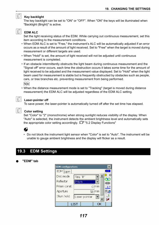
19. CHANGING THE SETTINGS
Key backlightThe key backlight can be set to "ON" or "OFF". When "ON" the keys will be illuminated when "Backlight (Bright)" is active.
EDM ALCSet the light receiving status of the EDM. While carrying out continuous measurement, set this item according to the measurement conditions.
• When EDM ALC is set to "Free," the instrument’s ALC will be automatically adjusted if an error occurs as a result of the amount of light received. Set to "Free" when the target is moved during measurement or different targets are used.
• When "Hold" is set, the amount of light received will not be adjusted until continuous measurement is completed.
• If an obstacle intermittently obstructs the light beam during continuous measurement and the "Signal off" error occurs, each time the obstruction occurs it takes some time for the amount of light received to be adjusted and the measurement value displayed. Set to "Hold" when the light beam used for measurement is stable but is frequently obstructed by obstacles such as people, cars, or tree branches etc. preventing measurement from being performed.
• When the distance measurement mode is set to "Tracking" (target is moved during distance measurement) the EDM ALC will be adjusted regardless of the EDM ALC setting.
Laser-pointer offTo save power, the laser-pointer is automatically turned off after the set time has elapsed.
Color settingSet "Color" to "2" (monochrome) when strong sunlight reduces visibility of the display. When "Auto" is selected, the instrument detects the ambient brightness level and automatically sets the appropriate color setting accordingly. "5.2 Display Functions"
• Do not block the instrument light sensor when "Color" is set to "Auto". The instrument will be unable to gauge ambient brightness and the display will flicker as a result.
"EDM" tab
19.3 EDM Settings
117
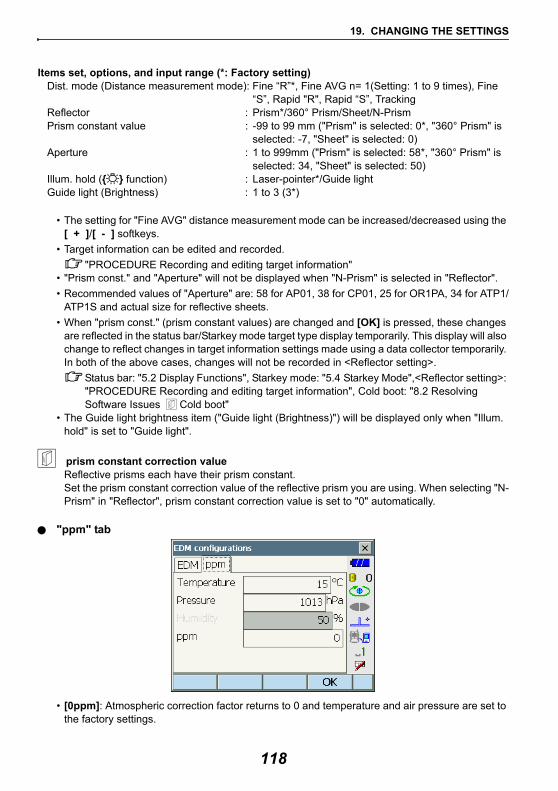
19. CHANGING THE SETTINGS
Items set, options, and input range (*: Factory setting)Dist. mode (Distance measurement mode): Fine “R”*, Fine AVG n= 1(Setting: 1 to 9 times), Fine
“S”, Rapid "R", Rapid “S”, TrackingReflector : Prism*/360° Prism/Sheet/N-PrismPrism constant value : -99 to 99 mm ("Prism" is selected: 0*, "360° Prism" is
selected: -7, "Sheet" is selected: 0)Aperture : 1 to 999mm ("Prism" is selected: 58*, "360° Prism" is
selected: 34, "Sheet" is selected: 50)Illum. hold ({ } function) : Laser-pointer*/Guide lightGuide light (Brightness) : 1 to 3 (3*)
• The setting for "Fine AVG" distance measurement mode can be increased/decreased using the [ + ]/[ - ] softkeys.
• Target information can be edited and recorded. "PROCEDURE Recording and editing target information"
• "Prism const." and "Aperture" will not be displayed when "N-Prism" is selected in "Reflector".• Recommended values of "Aperture" are: 58 for AP01, 38 for CP01, 25 for OR1PA, 34 for ATP1/
ATP1S and actual size for reflective sheets.• When "prism const." (prism constant values) are changed and [OK] is pressed, these changes
are reflected in the status bar/Starkey mode target type display temporarily. This display will also change to reflect changes in target information settings made using a data collector temporarily. In both of the above cases, changes will not be recorded in <Reflector setting>.
Status bar: "5.2 Display Functions", Starkey mode: "5.4 Starkey Mode",<Reflector setting>: "PROCEDURE Recording and editing target information", Cold boot: "8.2 Resolving Software Issues Cold boot"
• The Guide light brightness item ("Guide light (Brightness)") will be displayed only when "Illum. hold" is set to "Guide light".
prism constant correction valueReflective prisms each have their prism constant.Set the prism constant correction value of the reflective prism you are using. When selecting "N-Prism" in "Reflector", prism constant correction value is set to "0" automatically.
"ppm" tab
• [0ppm]: Atmospheric correction factor returns to 0 and temperature and air pressure are set to the factory settings.
118
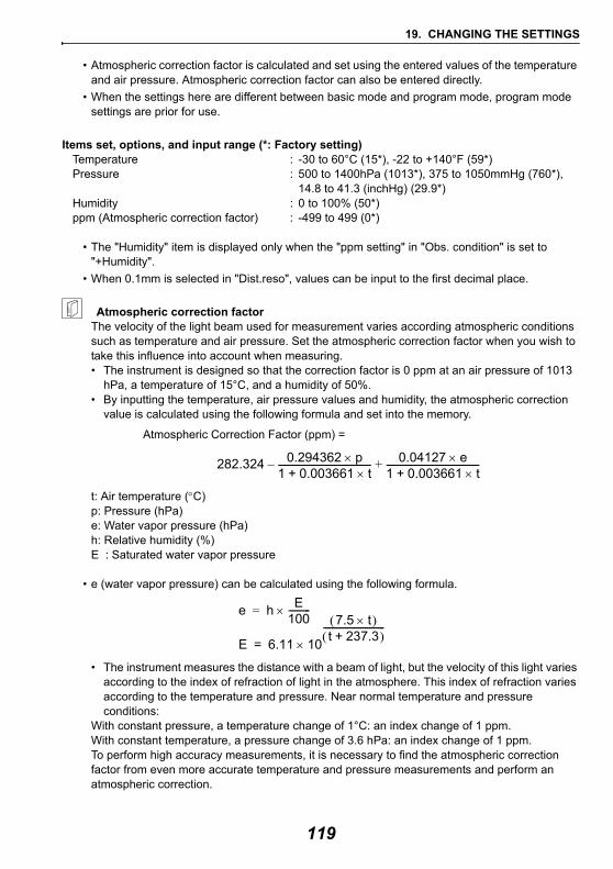
19. CHANGING THE SETTINGS
• Atmospheric correction factor is calculated and set using the entered values of the temperature and air pressure. Atmospheric correction factor can also be entered directly.
• When the settings here are different between basic mode and program mode, program mode settings are prior for use.
Items set, options, and input range (*: Factory setting)Temperature : -30 to 60°C (15*), -22 to +140°F (59*)Pressure : 500 to 1400hPa (1013*), 375 to 1050mmHg (760*),
14.8 to 41.3 (inchHg) (29.9*)Humidity : 0 to 100% (50*)ppm (Atmospheric correction factor) : -499 to 499 (0*)
• The "Humidity" item is displayed only when the "ppm setting" in "Obs. condition" is set to "+Humidity".
• When 0.1mm is selected in "Dist.reso", values can be input to the first decimal place.
Atmospheric correction factorThe velocity of the light beam used for measurement varies according atmospheric conditions such as temperature and air pressure. Set the atmospheric correction factor when you wish to take this influence into account when measuring.• The instrument is designed so that the correction factor is 0 ppm at an air pressure of 1013
hPa, a temperature of 15°C, and a humidity of 50%.• By inputting the temperature, air pressure values and humidity, the atmospheric correction
value is calculated using the following formula and set into the memory.
t: Air temperature (°C)p: Pressure (hPa)e: Water vapor pressure (hPa)h: Relative humidity (%)E : Saturated water vapor pressure
• e (water vapor pressure) can be calculated using the following formula.
• The instrument measures the distance with a beam of light, but the velocity of this light varies according to the index of refraction of light in the atmosphere. This index of refraction varies according to the temperature and pressure. Near normal temperature and pressure conditions:
With constant pressure, a temperature change of 1°C: an index change of 1 ppm.With constant temperature, a pressure change of 3.6 hPa: an index change of 1 ppm.To perform high accuracy measurements, it is necessary to find the atmospheric correction factor from even more accurate temperature and pressure measurements and perform an atmospheric correction.
282.324 0.294362 p×1 0.003661 t×+------------------------------------------– 0.04127 e×
1 0.003661 t×+------------------------------------------+
Atmospheric Correction Factor (ppm) =
E 6.11 10
7.5 t×( )t 237.3+( )
----------------------------×=
e h E100----------×=
119
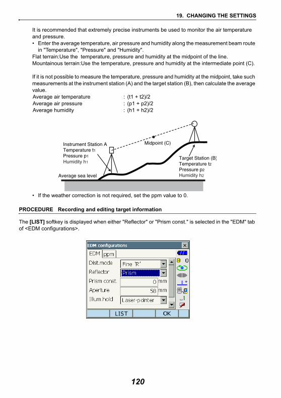
19. CHANGING THE SETTINGS
It is recommended that extremely precise instruments be used to monitor the air temperature and pressure.• Enter the average temperature, air pressure and humidity along the measurement beam route
in "Temperature", "Pressure" and "Humidity".Flat terrain:Use the temperature, pressure and humidity at the midpoint of the line.Mountainous terrain:Use the temperature, pressure and humidity at the intermediate point (C).
If it is not possible to measure the temperature, pressure and humidity at the midpoint, take such measurements at the instrument station (A) and the target station (B), then calculate the average value.
Average air temperature : (t1 + t2)/2 Average air pressure : (p1 + p2)/2 Average humidity : (h1 + h2)/2
• If the weather correction is not required, set the ppm value to 0.
PROCEDURE Recording and editing target information
The [LIST] softkey is displayed when either "Reflector" or "Prism const." is selected in the "EDM" tab of <EDM configurations>.
Humidity h1
Humidity h2
120
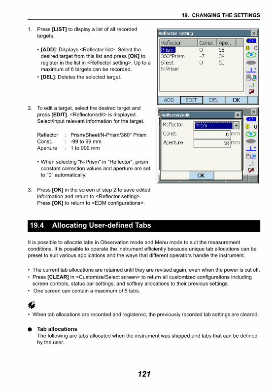
19. CHANGING THE SETTINGS
1. Press [LIST] to display a list of all recorded targets.
• [ADD]: Displays <Reflector list>. Select the desired target from this list and press [OK] to register in the list in <Reflector setting>. Up to a maximum of 6 targets can be recorded.
• [DEL]: Deletes the selected target.
2. To edit a target, select the desired target and press [EDIT]. <Reflector/edit> is displayed. Select/input relevant information for the target.
Reflector : Prism/Sheet/N-Prism/360° PrismConst. : -99 to 99 mmAperture : 1 to 999 mm
• When selecting "N-Prism" in "Reflector", prism constant correction values and aperture are set to "0" automatically.
3. Press [OK] in the screen of step 2 to save edited information and return to <Reflector setting>. Press [OK] to return to <EDM configurations>.
It is possible to allocate tabs in Observation mode and Menu mode to suit the measurement conditions. It is possible to operate the instrument efficiently because unique tab allocations can be preset to suit various applications and the ways that different operators handle the instrument.
• The current tab allocations are retained until they are revised again, even when the power is cut off.• Press [CLEAR] in <Customize/Select screen> to return all customized configurations including
screen controls, status bar settings, and softkey allocations to their previous settings.• One screen can contain a maximum of 5 tabs.
• When tab allocations are recorded and registered, the previously recorded tab settings are cleared.
Tab allocationsThe following are tabs allocated when the instrument was shipped and tabs that can be defined by the user.
19.4 Allocating User-defined Tabs
121
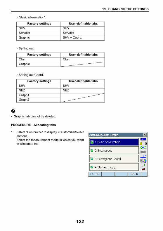
19. CHANGING THE SETTINGS
• "Basic observation"
• Setting out
• Setting out Coord.
• Graphic tab cannot be deleted.
PROCEDURE Allocating tabs
1. Select "Customize" to display <Customize/Select screen>.Select the measurement mode in which you want to allocate a tab.
Factory settings User-definable tabsSHV SHVSHVdist SHVdistGraphic SHV + Coord.
Factory settings User-definable tabsObs. Obs.Graphic
Factory settings User-definable tabsSHV SHVNEZ NEZGraph1Graph2
122
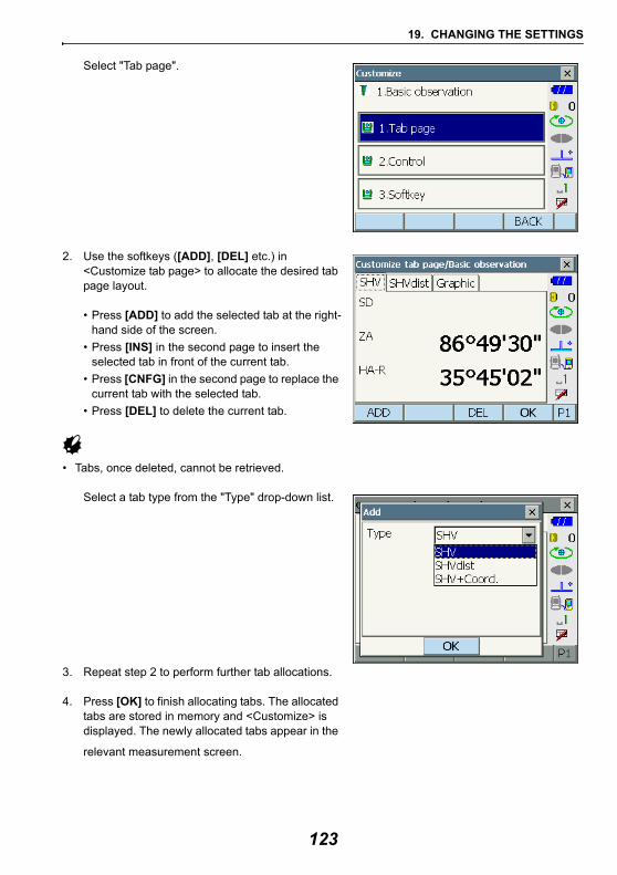
19. CHANGING THE SETTINGS
Select "Tab page".
2. Use the softkeys ([ADD], [DEL] etc.) in <Customize tab page> to allocate the desired tab page layout.
• Press [ADD] to add the selected tab at the right-hand side of the screen.
• Press [INS] in the second page to insert the selected tab in front of the current tab.
• Press [CNFG] in the second page to replace the current tab with the selected tab.
• Press [DEL] to delete the current tab.
• Tabs, once deleted, cannot be retrieved.
Select a tab type from the "Type" drop-down list.
3. Repeat step 2 to perform further tab allocations.
4. Press [OK] to finish allocating tabs. The allocated tabs are stored in memory and <Customize> is displayed. The newly allocated tabs appear in the
relevant measurement screen.
123
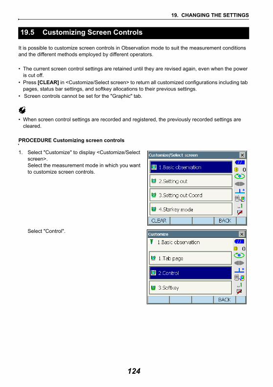
19. CHANGING THE SETTINGS
It is possible to customize screen controls in Observation mode to suit the measurement conditions and the different methods employed by different operators.
• The current screen control settings are retained until they are revised again, even when the power is cut off.
• Press [CLEAR] in <Customize/Select screen> to return all customized configurations including tab pages, status bar settings, and softkey allocations to their previous settings.
• Screen controls cannot be set for the "Graphic" tab.
• When screen control settings are recorded and registered, the previously recorded settings are cleared.
PROCEDURE Customizing screen controls
1. Select "Customize" to display <Customize/Select screen>.Select the measurement mode in which you want to customize screen controls.
Select "Control".
19.5 Customizing Screen Controls
124
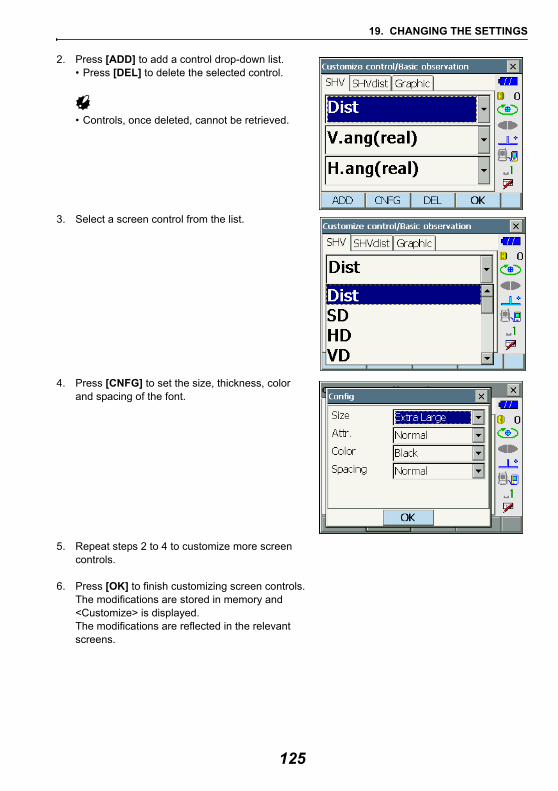
19. CHANGING THE SETTINGS
2. Press [ADD] to add a control drop-down list.• Press [DEL] to delete the selected control.
• Controls, once deleted, cannot be retrieved.
3. Select a screen control from the list.
4. Press [CNFG] to set the size, thickness, color and spacing of the font.
5. Repeat steps 2 to 4 to customize more screen controls.
6. Press [OK] to finish customizing screen controls. The modifications are stored in memory and <Customize> is displayed.The modifications are reflected in the relevant screens.
125
19. CHANGING THE SETTINGS
It is possible to allocate the softkeys in Observation mode to suit the measurement conditions. It is possible to operate the instrument efficiently because unique softkey allocations can be preset to suit various applications and the ways that different operators handle the instrument.
• The current softkey allocations are retained until they are revised again, even when the instrument is powered OFF.
• Press [CLEAR] in <Customize/Select screen> to return all customized configurations including tab pages, status bar/starkey mode settings, and screen controls to their previous settings.
• When softkey allocations are recorded and registered, the previously recorded key settings are cleared.
• Softkeys cannot be allocated to "Graphic" tabs.
Screens that can be customized and softkey allocations when shipped1. "SHV" and "SHVdist" tabs of <Basic observation>
Page 1 [SRCH] [MOTOR] [0SET] [MEAS]Page 2 [MENU] [EDM] [H-SET] [COORD]Page 3 [OFFSET] [RESEC] [REM] [S-O]
2. "Obs." tab of <Setting out>Page 1 [ --- ] [SHVR] [H.TURN] [MEAS]Page 2 [CNFG] [ --- ] [ --- ][REM]Page 3 [ --- ] [ --- ] [ --- ] [ --- ]
3. "SHV" and "NEZ" tabs of <Set out Coords>Page 1 [OK] [CNFG][H.TURN] [MEAS]Page 2 [ --- ] [ --- ] [ --- ] [ --- ]Page 3 [ --- ] [ --- ] [ --- ] [ --- ]
Functions that can be allocated to the softkeys[ --- ] : No functions set[MEAS] : Distance and angle measurement[0SET] : Set horizontal angle to 0°[H-SET] : Set required horizontal angle[SHV] : Switch the "SHV" tab and "SHVdist" tab (can only be allocated to 1
above)[R/L] : Select horizontal angle right/left. The capitalized letter in the softkey
indicates the currently selected mode.[ZA / %] : Switch between zenith angle/slope in %. The capitalized letter in the
softkey indicates the currently selected mode.[HOLD] : Hold horizontal angle/release horizontal angle[CALL] : Display final measurement data[HVOUT-S] : Output angle measurement results to an external device (SET format)
19.6 Allocating Key Functions
126
19. CHANGING THE SETTINGS
[HVDOUT-S] : Output distance and angle measurement results to an external device (SET format)
[NEZOUT-S] : Output coordinates data to an external device (SET format)[HVOUT-T] : Output angle measurement results to an external device (GTS format)
(can only be allocated to 1 above)[HVDOUT-T] : Output distance and angle measurement results to an external device
(GTS format) (can only be allocated to 1 above)[NEZOUT-T] : Output coordinates data to an external device (GTS format) (can only
be allocated to 1 above)[F/M] : Switch distance units between meters/feet[HT] : Set the instrument station, coordinates and instrument height[S-LEV] : Return signal[TILT] : Display tilt angle[MOTOR] : Display <Motor>[INV] : Rotates the instrument 180°[SRCH] : Automatically sights the center of the target[Fix Vel] : Fixed velocity rotation around vertical and horizontal axes[EDM] : EDM settings[MENU] : Display <Menu> (coordinate measurement, setting out measurement,
offset measurement, REM measurement, missing line measurement, resection, area calculation)
[COORD] : Coordinates measurement[S-O] : Setting-out measurement[OFFSET] : Offset measurement[A-OFS] : Angle offset menu[D-OFS] : Distance offset menu[2D-OFS] : Offset/2D menu [MLM] : Missing line measurement[REM] : REM measurement[RESEC] : Resection measurement[AREA] : Surface area measurement[CNFG] : Set setting out accuracy (can only be allocated to 2 and 3 above)[H.TURN] : Rotate the instrument to the entered horizontal angle. Rotate
horizontally to the angle for the setting out point when performing setting out (can only be allocated to 2 and 3 above).
[SHVR] : Switch distance mode between slope distance (SD)/horizontal distance (HD)/height difference (VD)/REM (R) in setting out screens. The capitalized letter in the softkey indicates the currently selected mode (can only be allocated to 2 above).
[OK] : Terminate setting out measurement for the selected setting out point and return to <Key in coord>. This setting out point will be removed from the list (can only be allocated to 3 above).
127
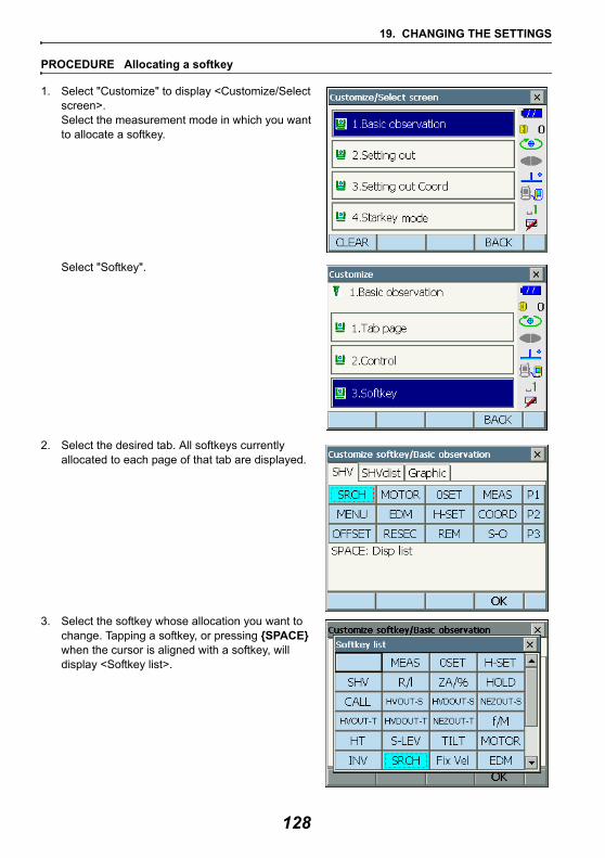
19. CHANGING THE SETTINGS
PROCEDURE Allocating a softkey
1. Select "Customize" to display <Customize/Select screen>.Select the measurement mode in which you want to allocate a softkey.
Select "Softkey".
2. Select the desired tab. All softkeys currently allocated to each page of that tab are displayed.
3. Select the softkey whose allocation you want to change. Tapping a softkey, or pressing {SPACE} when the cursor is aligned with a softkey, will display <Softkey list>.
128
19. CHANGING THE SETTINGS
4. Select the desired softkey from <Softkey list> to allocate to the position specified in step 3.
5. Repeat steps 3 to 4 to perform further key allocations.
6. Press [OK] to finish allocating keys. The allocated keys are stored in memory and <Customize> is displayed. The newly allocated keys appear in the relevant measurement screen.
It is possible to preset icon allocations of the Starkey mode to suit various applications and the ways that different operators handle the instrument.
• The current icon allocations are retained until they are revised again, even when the power is turned off.
• Press [CLEAR] in <Customize/Select screen> to return all customized configurations including tab pages, screen controls and softkey allocations to their previous settings.
• When icon allocations are recorded and registered, the previously recorded settings are cleared.• When icon allocations are recorded and registered, the setting reflects to Status bar.
Icons that can be allocated to the status barRemaining battery powerTarget displayMotorLaser-pointer/guide lightTilt angle compensationCommunication statusInput modeSIP (Input panel)ppm (atmospheric correction factor)Touch panelDiskNo icon
19.7 Changing Starkey Mode Icons
129
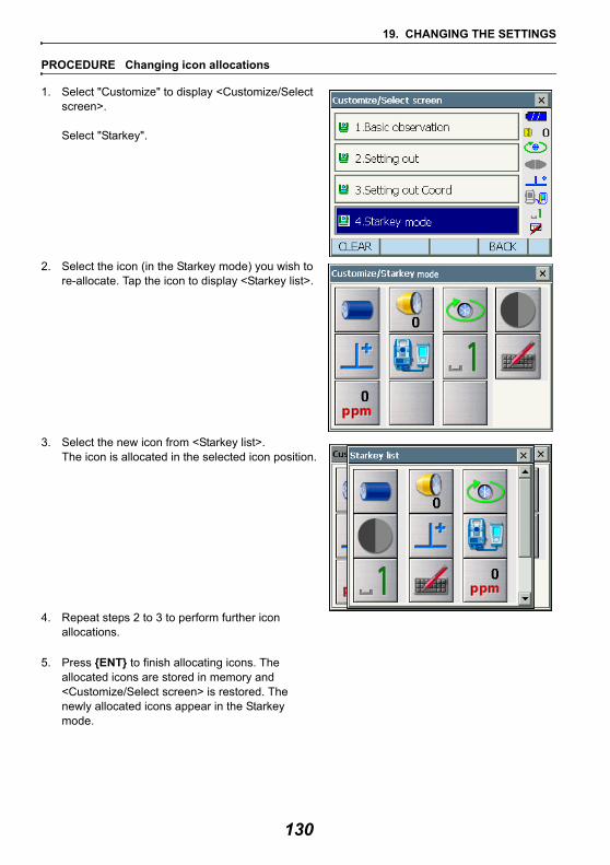
19. CHANGING THE SETTINGS
PROCEDURE Changing icon allocations
1. Select "Customize" to display <Customize/Select screen>.
Select "Starkey".
2. Select the icon (in the Starkey mode) you wish to re-allocate. Tap the icon to display <Starkey list>.
3. Select the new icon from <Starkey list>.The icon is allocated in the selected icon position.
4. Repeat steps 2 to 3 to perform further icon allocations.
5. Press {ENT} to finish allocating icons. The allocated icons are stored in memory and <Customize/Select screen> is restored. The newly allocated icons appear in the Starkey mode.
130
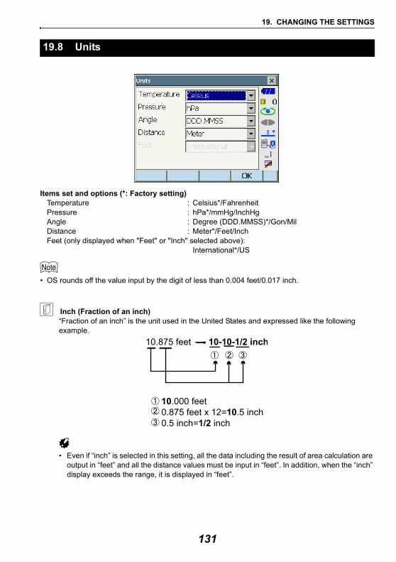
19. CHANGING THE SETTINGS
Items set and options (*: Factory setting)Temperature : Celsius*/FahrenheitPressure : hPa*/mmHg/InchHgAngle : Degree (DDD.MMSS)*/Gon/MilDistance : Meter*/Feet/InchFeet (only displayed when "Feet" or "Inch" selected above):
International*/US
• OS rounds off the value input by the digit of less than 0.004 feet/0.017 inch.
Inch (Fraction of an inch)“Fraction of an inch” is the unit used in the United States and expressed like the following example.
• Even if “inch” is selected in this setting, all the data including the result of area calculation are output in “feet” and all the distance values must be input in “feet”. In addition, when the “inch” display exceeds the range, it is displayed in “feet”.
19.8 Units
131
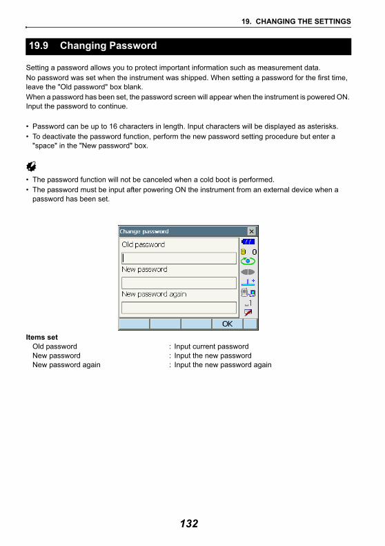
19. CHANGING THE SETTINGS
Setting a password allows you to protect important information such as measurement data.No password was set when the instrument was shipped. When setting a password for the first time, leave the "Old password" box blank.When a password has been set, the password screen will appear when the instrument is powered ON. Input the password to continue.
• Password can be up to 16 characters in length. Input characters will be displayed as asterisks. • To deactivate the password function, perform the new password setting procedure but enter a
"space" in the "New password" box.
• The password function will not be canceled when a cold boot is performed.• The password must be input after powering ON the instrument from an external device when a
password has been set.
Items set Old password : Input current passwordNew password : Input the new passwordNew password again : Input the new password again
19.9 Changing Password
132
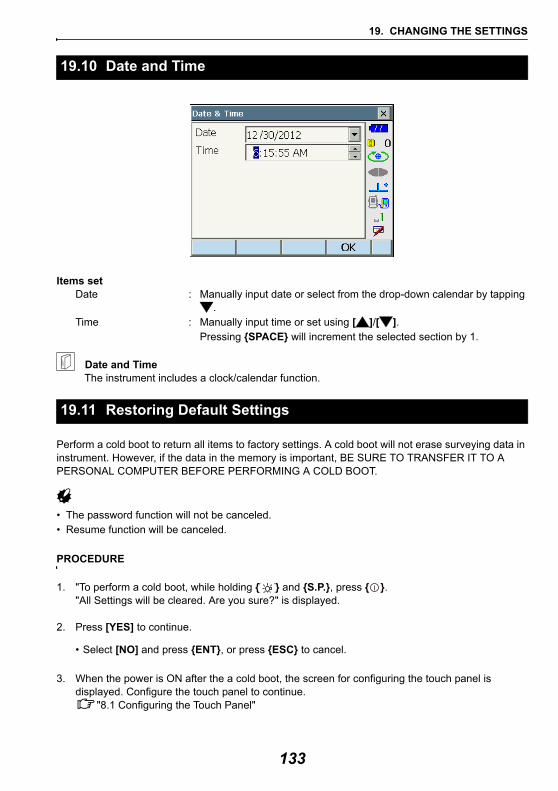
19. CHANGING THE SETTINGS
Items set Date : Manually input date or select from the drop-down calendar by tapping
. Time : Manually input time or set using [ ]/[ ].
Pressing {SPACE} will increment the selected section by 1.
Date and TimeThe instrument includes a clock/calendar function.
Perform a cold boot to return all items to factory settings. A cold boot will not erase surveying data in instrument. However, if the data in the memory is important, BE SURE TO TRANSFER IT TO A PERSONAL COMPUTER BEFORE PERFORMING A COLD BOOT.
• The password function will not be canceled.• Resume function will be canceled.
PROCEDURE
1. "To perform a cold boot, while holding { } and {S.P.}, press { }."All Settings will be cleared. Are you sure?" is displayed.
2. Press [YES] to continue.
• Select [NO] and press {ENT}, or press {ESC} to cancel.
3. When the power is ON after the a cold boot, the screen for configuring the touch panel is displayed. Configure the touch panel to continue.
"8.1 Configuring the Touch Panel"
19.10 Date and Time
19.11 Restoring Default Settings
133
20.WARNING AND ERROR MESSAGES
The following is a list of the error messages displayed by the instrument and the meaning of each message. If the same error message is repeated or if any message not shown below appears, the instrument has malfunctioned. Contact your local dealer.Backup battery dead. Clock display may no longer be correct.The voltage supplied by the lithium battery either declines or is completely discharged.Ask your local dealer to replace the battery for you.
Bad conditionThe air is shimmering a lot, etc., measuring conditions are poor.
The center of the target cannot be sighted.Resight the target.
Unsuitable distance measurement conditions when reflectorless measurement is set. When reflectorless measurement is set, distance cannot be measured because the laser beam is striking at least two surfaces at the same time.Choose a single surface target for distance measurement.
Precautions for setting prism: "10. TARGET SIGHTING"
Calculation errorDuring resection measurement the same point is registered multiple times. Set another known point so that the known point coordinates do not coincide.
Coordinates identical to the known point coordinates observed during resection exist.
During surface area calculation, conditions necessary for calculations are not met. Check conditions and try again.
An error occurred during calculation.
Device list is full !!No more Bluetooth devices can currently be registered. Delete unnecessary devices from the list and try again.
Disconnect BluetoothWireless connection disconnected. Re-connect and try again.
Error: Read Build Info.Error: Read JOG SettingError: Read OS ParameterError: Read sysflgError: Self checkError: Write sysflg
Press [OK] to cancel the message. If this error message appears frequently, contact your local dealer.
Incorrect password.Input password does not match set password.Input correct password.
134
20. WARNING AND ERROR MESSAGES
Input device name !!Bluetooth device name not input. Input device name and complete device registration.
Input over 3 letters !The input password consists of less than 3 characters. Input a password at least 3 characters in length.
Motor error EXXXA problem has occurred with the motor drive and operation stops. Power the instrument OFF then ON to correct the problem.If this error message appears frequently, contact your local dealer.
Need base pt. obsDuring REM measurement, the observation of the target was not completed normally. Reset and sight the prism and perform measurement again.
Need 1st obsDuring missing line measurement, the observation of the starting position was not completed normally.Sight the starting position accurately and press [MEAS] to perform the measurement again.
New password Diff.During new password setting, the passwords input twice are different.Input new password twice correctly.
No solution The calculation of the instrument station coordinates during resection does not converge.Access the results and if necessary, perform the observations again.
Out of rangeDuring gradient % display, the display range (less than ± 1000%) has been exceeded.During REM measurement, either the vertical angle has exceeded horizontal ±89° or the measured distance is greater than 9999.999m.Install the instrument station far from the target.
Please input an address consisting of 12 hexadecimal characters (0 to 9, A to F)The Bluetooth address is not input correctly for Bluetooth communication. Input the Bluetooth address with 12 characters of 0 to 9 or A to F.
Signal offThe reflected light is not observed when distance measurement begins. Or, during measurement, the reflected light has weakened or is blocked.Either sight the target again or, when using a reflective prism, increase the number of reflective prisms.
Target not found !!The prism cannot be found within the Search area range.Reset and sight the prism and perform measurement again.
135
20. WARNING AND ERROR MESSAGES
Temp Rnge OUTThe instrument is outside useable temperature range and accurate measurement cannot be performed. Repeat measurement within the appropriate temperature range.
Tilt over range !!The tilt angle exceeds the tilt angle compensation range of the sensor. Level the instrument again.
Time out !!Measurement is not carried out in the allotted time.Reset and sight the prism and perform measurement again.
When designating the angle of rotation or automatically sighting the prism, there is a problem with the positioning of the prism or the operation of the instrument and measurement is not obtained within the fixed time. Check the positioning of the instrument and prism and perform measurement again. If observation is still not possible, sight the target manually.
When the telescope turns to nadir, it is not possible to search !!The instrument cannot perform a search during Auto Pointing when the telescope is directed to the nadir angle.Set the telescope position within the measuring range and perform measurement again.
136
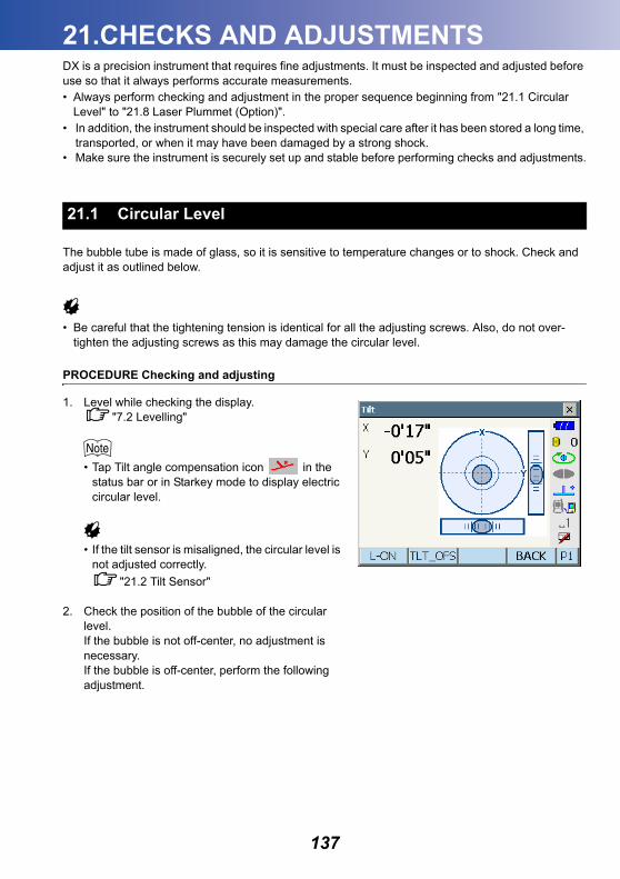
21.CHECKS AND ADJUSTMENTS
DX is a precision instrument that requires fine adjustments. It must be inspected and adjusted before use so that it always performs accurate measurements.• Always perform checking and adjustment in the proper sequence beginning from "21.1 CircularLevel" to "21.8 Laser Plummet (Option)".• In addition, the instrument should be inspected with special care after it has been stored a long time,
transported, or when it may have been damaged by a strong shock.• Make sure the instrument is securely set up and stable before performing checks and adjustments.
The bubble tube is made of glass, so it is sensitive to temperature changes or to shock. Check and adjust it as outlined below.
• Be careful that the tightening tension is identical for all the adjusting screws. Also, do not over-tighten the adjusting screws as this may damage the circular level.
PROCEDURE Checking and adjusting
1. Level while checking the display."7.2 Levelling"
• Tap Tilt angle compensation icon in the status bar or in Starkey mode to display electric circular level.
• If the tilt sensor is misaligned, the circular level is not adjusted correctly.
"21.2 Tilt Sensor"
2. Check the position of the bubble of the circular level.If the bubble is not off-center, no adjustment is necessary.If the bubble is off-center, perform the following adjustment.
21.1 Circular Level
137
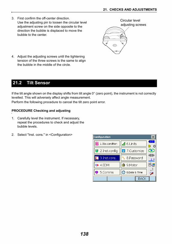
21. CHECKS AND ADJUSTMENTS
3. First confirm the off-center direction.Use the adjusting pin to loosen the circular level adjustment screw on the side opposite to the direction the bubble is displaced to move the bubble to the center.
4. Adjust the adjusting screws until the tightening tension of the three screws is the same to align the bubble in the middle of the circle.
If the tilt angle shown on the display shifts from tilt angle 0° (zero point), the instrument is not correctly levelled. This will adversely affect angle measurement. Perform the following procedure to cancel the tilt zero point error.
PROCEDURE Checking and adjusting
1. Carefully level the instrument. If necessary, repeat the procedures to check and adjust the bubble levels.
2. Select "Inst. cons." in <Configuration>
21.2 Tilt Sensor
138
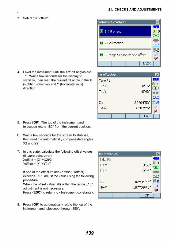
21. CHECKS AND ADJUSTMENTS
3. Select "Tilt offset".
4. Level the instrument until the X/Y tilt angles are ±1’. Wait a few seconds for the display to stabilize, then read the current tilt angle in the X (sighting) direction and Y (horizontal axis) direction.
5. Press [OK]. The top of the instrument and telescope rotate 180° from the current position.
6. Wait a few seconds for the screen to stabilize, then read the automatically compensated angles X2 and Y2.
7. In this state, calculate the following offset values (tilt zero point error). Xoffset = (X1+X2)/2Yoffset = (Y1+Y2)/2
If one of the offset values (Xoffset, Yoffset) exceeds ±10", adjust the value using the following procedure.When the offset value falls within the range ±10", adjustment is not necessary. Press {ESC} to return to <Instrument constants>.
8. Press [OK] to automatically rotate the top of the instrument and telescope through 180°.
139
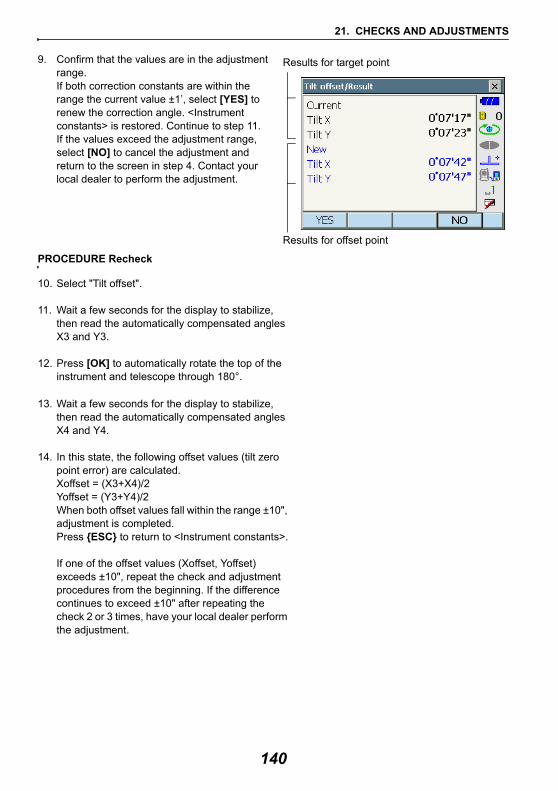
21. CHECKS AND ADJUSTMENTS
9. Confirm that the values are in the adjustment range.If both correction constants are within the range the current value ±1’, select [YES] to renew the correction angle. <Instrument constants> is restored. Continue to step 11.If the values exceed the adjustment range, select [NO] to cancel the adjustment and return to the screen in step 4. Contact your local dealer to perform the adjustment.
PROCEDURE Recheck
10. Select "Tilt offset".
11. Wait a few seconds for the display to stabilize, then read the automatically compensated angles X3 and Y3.
12. Press [OK] to automatically rotate the top of the instrument and telescope through 180°.
13. Wait a few seconds for the display to stabilize, then read the automatically compensated angles X4 and Y4.
14. In this state, the following offset values (tilt zero point error) are calculated.Xoffset = (X3+X4)/2Yoffset = (Y3+Y4)/2When both offset values fall within the range ±10", adjustment is completed. Press {ESC} to return to <Instrument constants>.
If one of the offset values (Xoffset, Yoffset) exceeds ±10", repeat the check and adjustment procedures from the beginning. If the difference continues to exceed ±10" after repeating the check 2 or 3 times, have your local dealer perform the adjustment.
Results for target point
Results for offset point
140
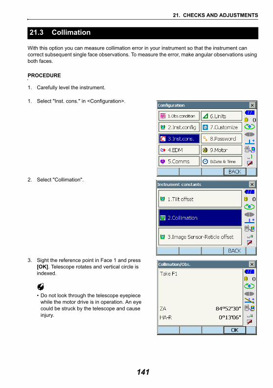
21. CHECKS AND ADJUSTMENTS
With this option you can measure collimation error in your instrument so that the instrument can correct subsequent single face observations. To measure the error, make angular observations using both faces.
PROCEDURE
1. Carefully level the instrument.
1. Select "Inst. cons." in <Configuration>.
2. Select "Collimation".
3. Sight the reference point in Face 1 and press [OK]. Telescope rotates and vertical circle is indexed.
• Do not look through the telescope eyepiece while the motor drive is in operation. An eye could be struck by the telescope and cause injury.
21.3 Collimation
141
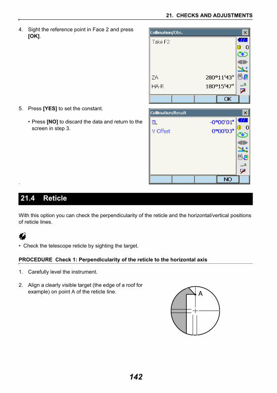
21. CHECKS AND ADJUSTMENTS
4. Sight the reference point in Face 2 and press [OK].
5. Press [YES] to set the constant.
• Press [NO] to discard the data and return to the screen in step 3.
.
With this option you can check the perpendicularity of the reticle and the horizontal/vertical positions of reticle lines.
• Check the telescope reticle by sighting the target.
PROCEDURE Check 1: Perpendicularity of the reticle to the horizontal axis
1. Carefully level the instrument.
2. Align a clearly visible target (the edge of a roof for example) on point A of the reticle line.
21.4 Reticle
142
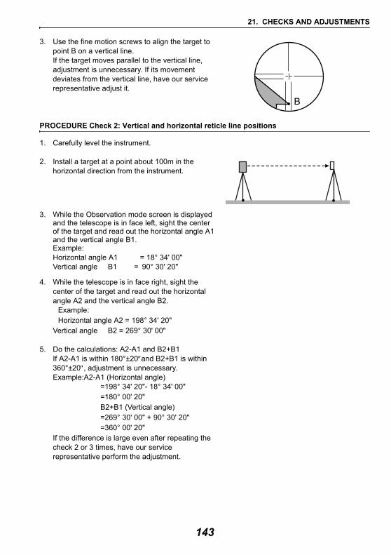
21. CHECKS AND ADJUSTMENTS
3. Use the fine motion screws to align the target to point B on a vertical line. If the target moves parallel to the vertical line, adjustment is unnecessary. If its movement deviates from the vertical line, have our service representative adjust it.
PROCEDURE Check 2: Vertical and horizontal reticle line positions
1. Carefully level the instrument.
2. Install a target at a point about 100m in the horizontal direction from the instrument.
3. While the Observation mode screen is displayed and the telescope is in face left, sight the center of the target and read out the horizontal angle A1 and the vertical angle B1.Example:Horizontal angle A1 = 18° 34' 00"Vertical angle B1 = 90° 30' 20"
4. While the telescope is in face right, sight the center of the target and read out the horizontal angle A2 and the vertical angle B2.
Example:Horizontal angle A2 = 198° 34' 20"
Vertical angle B2 = 269° 30' 00"
5. Do the calculations: A2-A1 and B2+B1If A2-A1 is within 180°±20″and B2+B1 is within 360°±20″, adjustment is unnecessary.Example:A2-A1 (Horizontal angle)
=198° 34' 20"- 18° 34' 00"=180° 00' 20"B2+B1 (Vertical angle)=269° 30' 00" + 90° 30' 20"=360° 00' 20"
If the difference is large even after repeating the check 2 or 3 times, have our service representative perform the adjustment.
143
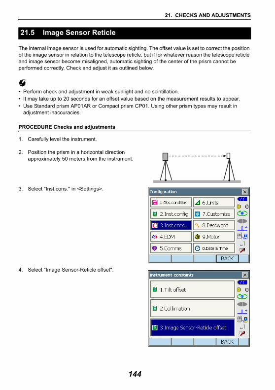
21. CHECKS AND ADJUSTMENTS
The internal image sensor is used for automatic sighting. The offset value is set to correct the position of the image sensor in relation to the telescope reticle, but if for whatever reason the telescope reticle and image sensor become misaligned, automatic sighting of the center of the prism cannot be performed correctly. Check and adjust it as outlined below.
• Perform check and adjustment in weak sunlight and no scintillation.• It may take up to 20 seconds for an offset value based on the measurement results to appear.• Use Standard prism AP01AR or Compact prism CP01. Using other prism types may result in
adjustment inaccuracies.
PROCEDURE Checks and adjustments
1. Carefully level the instrument.
2. Position the prism in a horizontal direction approximately 50 meters from the instrument.
3. Select "Inst.cons." in <Settings>.
4. Select "Image Sensor-Reticle offset".
21.5 Image Sensor Reticle
144
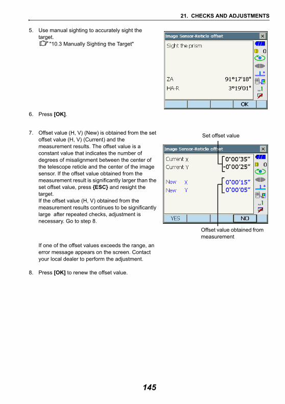
21. CHECKS AND ADJUSTMENTS
5. Use manual sighting to accurately sight the target.
"10.3 Manually Sighting the Target"
6. Press [OK].
7. Offset value (H, V) (New) is obtained from the set offset value (H, V) (Current) and the measurement results. The offset value is a constant value that indicates the number of degrees of misalignment between the center of the telescope reticle and the center of the image sensor. If the offset value obtained from the measurement result is significantly larger than the set offset value, press {ESC} and resight the target.If the offset value (H, V) obtained from the measurement results continues to be significantly large after repeated checks, adjustment is necessary. Go to step 8.
If one of the offset values exceeds the range, an error message appears on the screen. Contact your local dealer to perform the adjustment.
8. Press [OK] to renew the offset value.
Set offset value
Offset value obtained from measurement
145
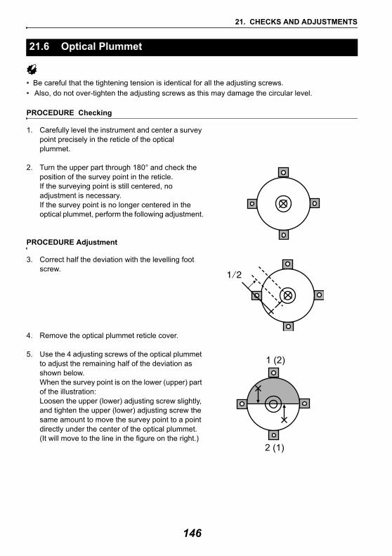
21. CHECKS AND ADJUSTMENTS
• Be careful that the tightening tension is identical for all the adjusting screws.• Also, do not over-tighten the adjusting screws as this may damage the circular level.
PROCEDURE Checking
1. Carefully level the instrument and center a survey point precisely in the reticle of the optical plummet.
2. Turn the upper part through 180° and check the position of the survey point in the reticle.If the surveying point is still centered, no adjustment is necessary.If the survey point is no longer centered in the optical plummet, perform the following adjustment.
PROCEDURE Adjustment
3. Correct half the deviation with the levelling foot screw.
4. Remove the optical plummet reticle cover.
5. Use the 4 adjusting screws of the optical plummet to adjust the remaining half of the deviation as shown below. When the survey point is on the lower (upper) part of the illustration:Loosen the upper (lower) adjusting screw slightly, and tighten the upper (lower) adjusting screw the same amount to move the survey point to a point directly under the center of the optical plummet.(It will move to the line in the figure on the right.)
21.6 Optical Plummet
1 (2)
2 (1)
146
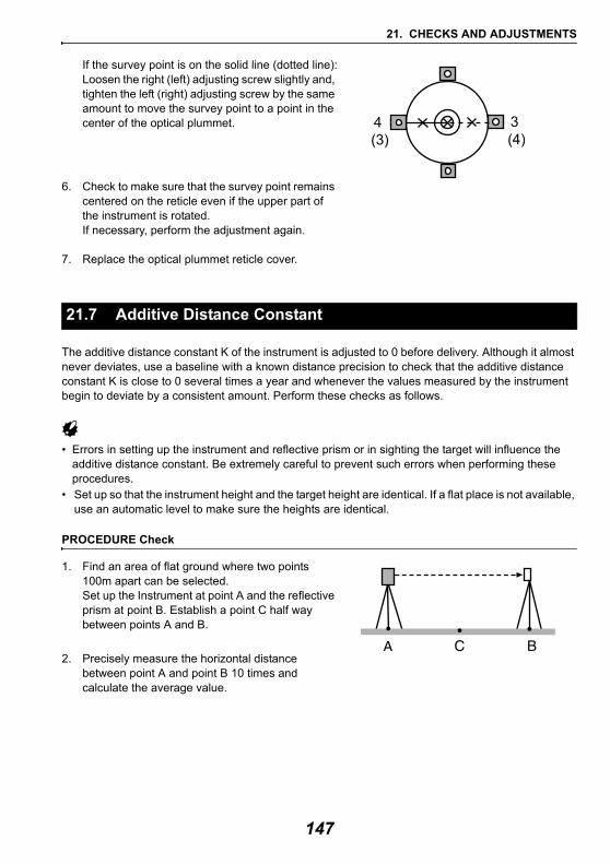
21. CHECKS AND ADJUSTMENTS
If the survey point is on the solid line (dotted line):Loosen the right (left) adjusting screw slightly and, tighten the left (right) adjusting screw by the same amount to move the survey point to a point in the center of the optical plummet.
6. Check to make sure that the survey point remains centered on the reticle even if the upper part of the instrument is rotated. If necessary, perform the adjustment again.
7. Replace the optical plummet reticle cover.
The additive distance constant K of the instrument is adjusted to 0 before delivery. Although it almost never deviates, use a baseline with a known distance precision to check that the additive distance constant K is close to 0 several times a year and whenever the values measured by the instrument begin to deviate by a consistent amount. Perform these checks as follows.
• Errors in setting up the instrument and reflective prism or in sighting the target will influence the additive distance constant. Be extremely careful to prevent such errors when performing these procedures.
• Set up so that the instrument height and the target height are identical. If a flat place is not available, use an automatic level to make sure the heights are identical.
PROCEDURE Check
1. Find an area of flat ground where two points 100m apart can be selected. Set up the Instrument at point A and the reflective prism at point B. Establish a point C half way between points A and B.
2. Precisely measure the horizontal distance between point A and point B 10 times and calculate the average value.
21.7 Additive Distance Constant
4 (3)
3 (4)
147
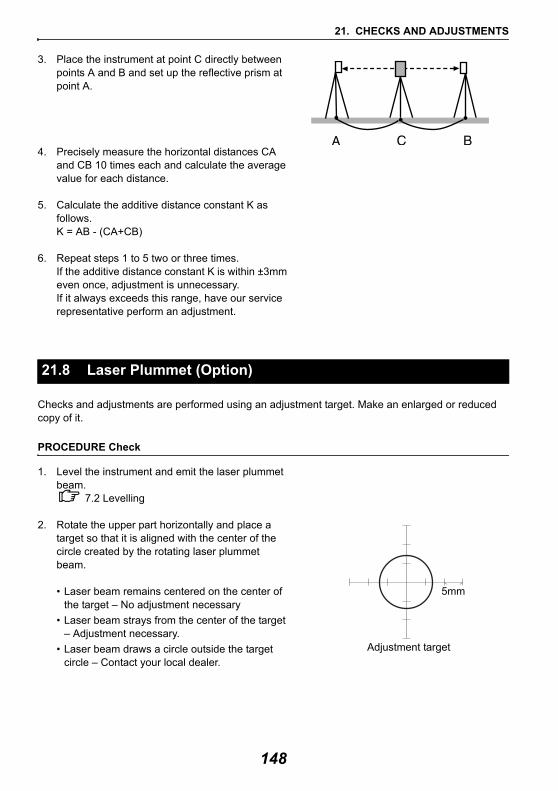
21. CHECKS AND ADJUSTMENTS
3. Place the instrument at point C directly between points A and B and set up the reflective prism at point A.
4. Precisely measure the horizontal distances CA and CB 10 times each and calculate the average value for each distance.
5. Calculate the additive distance constant K as follows.K = AB - (CA+CB)
6. Repeat steps 1 to 5 two or three times. If the additive distance constant K is within ±3mm even once, adjustment is unnecessary. If it always exceeds this range, have our service representative perform an adjustment.
Checks and adjustments are performed using an adjustment target. Make an enlarged or reduced copy of it.
PROCEDURE Check
1. Level the instrument and emit the laser plummet beam.
7.2 Levelling
2. Rotate the upper part horizontally and place a target so that it is aligned with the center of the circle created by the rotating laser plummet beam.
• Laser beam remains centered on the center of the target – No adjustment necessary
• Laser beam strays from the center of the target – Adjustment necessary.
• Laser beam draws a circle outside the target circle – Contact your local dealer.
21.8 Laser Plummet (Option)
5mm
Adjustment target
148
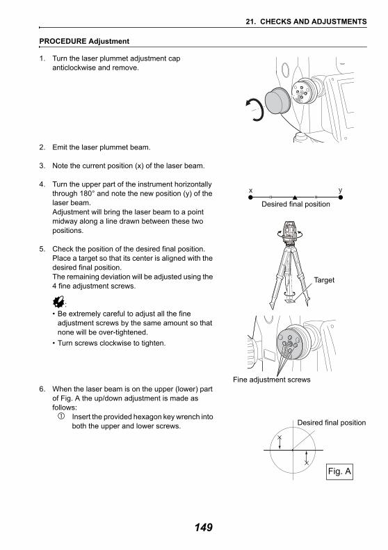
21. CHECKS AND ADJUSTMENTS
PROCEDURE Adjustment
1. Turn the laser plummet adjustment cap anticlockwise and remove.
2. Emit the laser plummet beam.
3. Note the current position (x) of the laser beam.
4. Turn the upper part of the instrument horizontally through 180° and note the new position (y) of the laser beam.Adjustment will bring the laser beam to a point midway along a line drawn between these two positions.
5. Check the position of the desired final position. Place a target so that its center is aligned with the desired final position.The remaining deviation will be adjusted using the 4 fine adjustment screws.
:• Be extremely careful to adjust all the fine
adjustment screws by the same amount so that none will be over-tightened.
• Turn screws clockwise to tighten.
6. When the laser beam is on the upper (lower) part of Fig. A the up/down adjustment is made as follows:
Insert the provided hexagon key wrench into both the upper and lower screws.
x y
Desired final position
Target
Fine adjustment screws
Fig. A
Desired final position
149
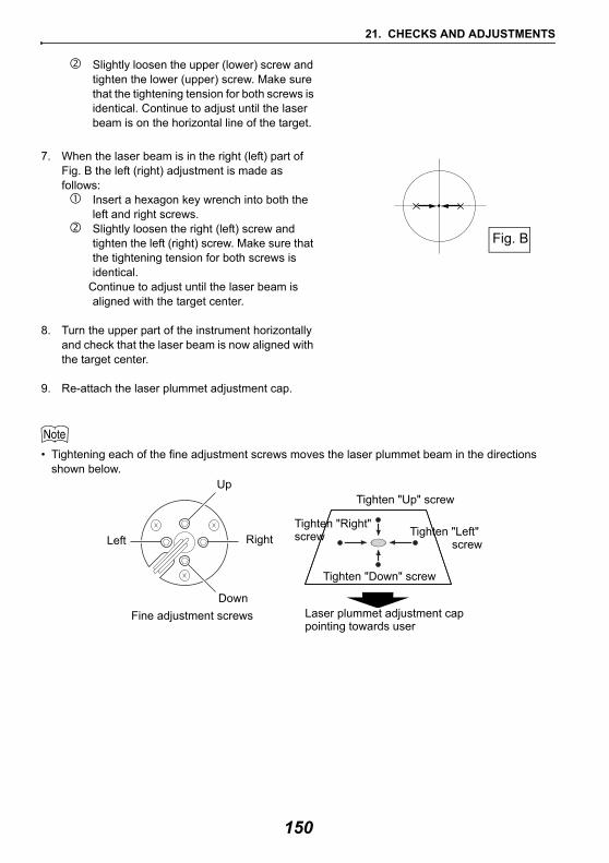
21. CHECKS AND ADJUSTMENTS
Slightly loosen the upper (lower) screw and tighten the lower (upper) screw. Make sure that the tightening tension for both screws is identical. Continue to adjust until the laser beam is on the horizontal line of the target.
7. When the laser beam is in the right (left) part of Fig. B the left (right) adjustment is made as follows:
Insert a hexagon key wrench into both the left and right screws.Slightly loosen the right (left) screw and tighten the left (right) screw. Make sure that the tightening tension for both screws is identical.
Continue to adjust until the laser beam is aligned with the target center.
8. Turn the upper part of the instrument horizontally and check that the laser beam is now aligned with the target center.
9. Re-attach the laser plummet adjustment cap.
• Tightening each of the fine adjustment screws moves the laser plummet beam in the directions shown below.
Fig. B
Up
RightLeft
Down
Tighten "Up" screw
Tighten "Left" screw
Tighten "Down" screw
Tighten "Right"screw
Fine adjustment screws Laser plummet adjustment cappointing towards user
150
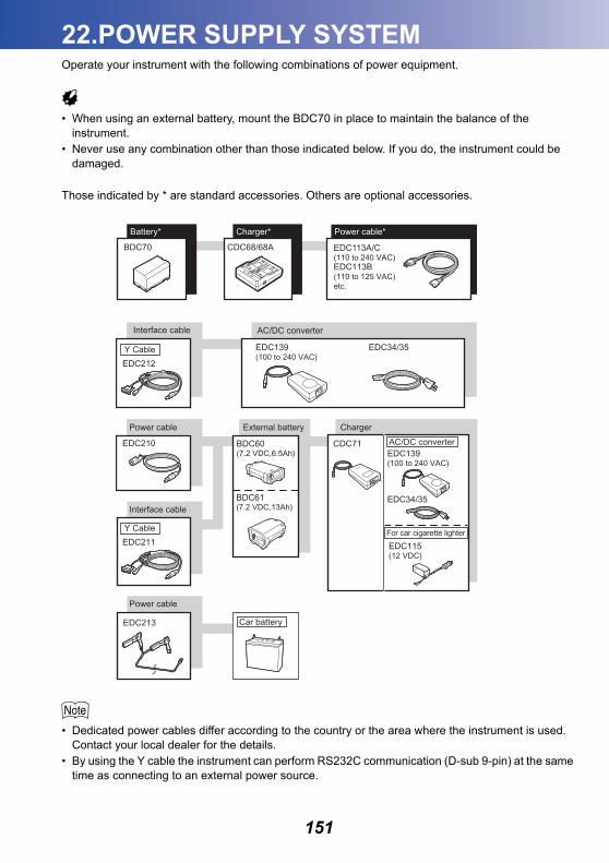
22.POWER SUPPLY SYSTEM
Operate your instrument with the following combinations of power equipment.• When using an external battery, mount the BDC70 in place to maintain the balance of the instrument.
• Never use any combination other than those indicated below. If you do, the instrument could be damaged.
Those indicated by * are standard accessories. Others are optional accessories.
• Dedicated power cables differ according to the country or the area where the instrument is used. Contact your local dealer for the details.
• By using the Y cable the instrument can perform RS232C communication (D-sub 9-pin) at the same time as connecting to an external power source.
BDC70 CDC68/68A EDC113A/C (110 to 240 VAC)EDC113B (110 to 125 VAC)etc.
ChargerExternal battery
For car cigarette lighter
AC/DC converter
Battery* Charger* Power cable*
Interface cable
Power cable
Power cable
Interface cable AC/DC converter
Car battery
151
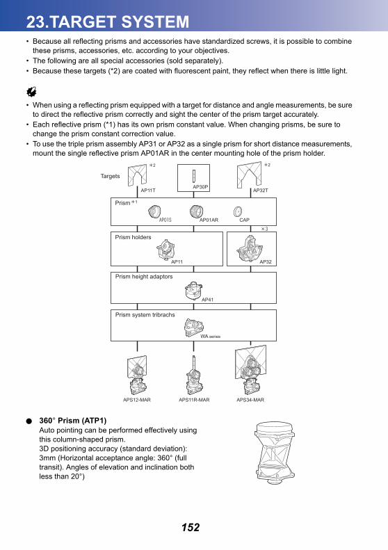
23.TARGET SYSTEM
• Because all reflecting prisms and accessories have standardized screws, it is possible to combinethese prisms, accessories, etc. according to your objectives.• The following are all special accessories (sold separately).• Because these targets (*2) are coated with fluorescent paint, they reflect when there is little light.
• When using a reflecting prism equipped with a target for distance and angle measurements, be sure to direct the reflective prism correctly and sight the center of the prism target accurately.
• Each reflective prism (*1) has its own prism constant value. When changing prisms, be sure to change the prism constant correction value.
• To use the triple prism assembly AP31 or AP32 as a single prism for short distance measurements, mount the single reflective prism AP01AR in the center mounting hole of the prism holder.
360° Prism (ATP1)Auto pointing can be performed effectively using this column-shaped prism.3D positioning accuracy (standard deviation): 3mm (Horizontal acceptance angle: 360° (full transit). Angles of elevation and inclination both less than 20°)
AP30P
AP11
APS12-MAR APS34-MARAPS11R-MAR
AP41
WA series
AP32
AP11T AP32T
AP01AR CAP
Prism
Targets
Prism holders
Prism height adaptors
Prism system tribrachs
2 2
1
152
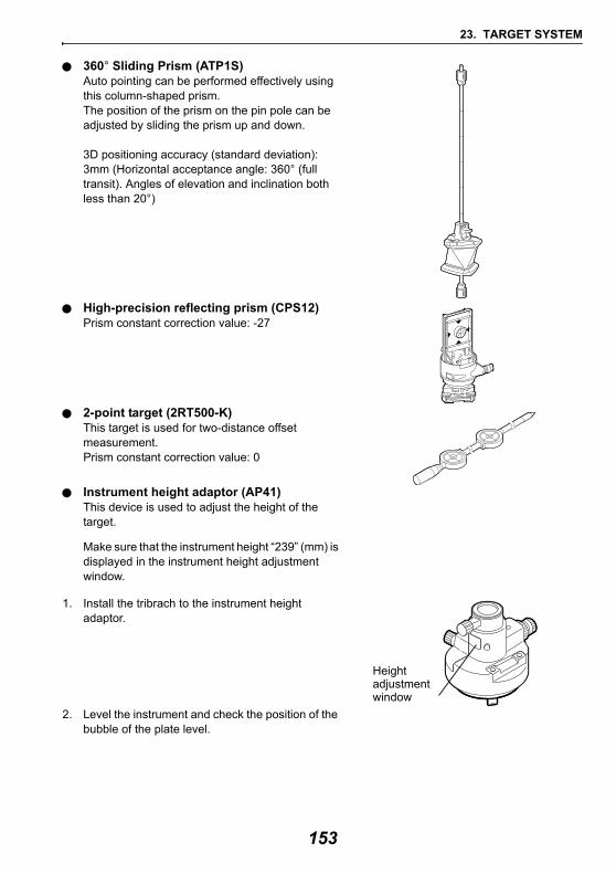
23. TARGET SYSTEM
360° Sliding Prism (ATP1S)Auto pointing can be performed effectively using this column-shaped prism.The position of the prism on the pin pole can be adjusted by sliding the prism up and down.
3D positioning accuracy (standard deviation): 3mm (Horizontal acceptance angle: 360° (full transit). Angles of elevation and inclination both less than 20°)
High-precision reflecting prism (CPS12)Prism constant correction value: -27
2-point target (2RT500-K)This target is used for two-distance offset measurement.Prism constant correction value: 0
Instrument height adaptor (AP41)This device is used to adjust the height of the target.
Make sure that the instrument height “239” (mm) is displayed in the instrument height adjustment window.
1. Install the tribrach to the instrument height adaptor.
2. Level the instrument and check the position of the bubble of the plate level.
Heightadjustmentwindow
153
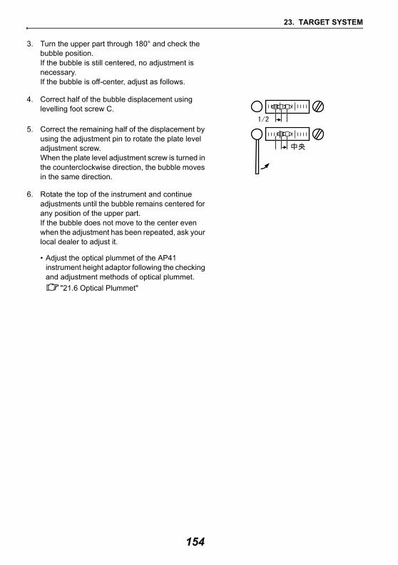
23. TARGET SYSTEM
3. Turn the upper part through 180° and check the bubble position.If the bubble is still centered, no adjustment is necessary.If the bubble is off-center, adjust as follows.
4. Correct half of the bubble displacement using levelling foot screw C.
5. Correct the remaining half of the displacement by using the adjustment pin to rotate the plate level adjustment screw. When the plate level adjustment screw is turned in the counterclockwise direction, the bubble moves in the same direction.
6. Rotate the top of the instrument and continue adjustments until the bubble remains centered for any position of the upper part.If the bubble does not move to the center even when the adjustment has been repeated, ask your local dealer to adjust it.
• Adjust the optical plummet of the AP41 instrument height adaptor following the checking and adjustment methods of optical plummet.
"21.6 Optical Plummet"
154
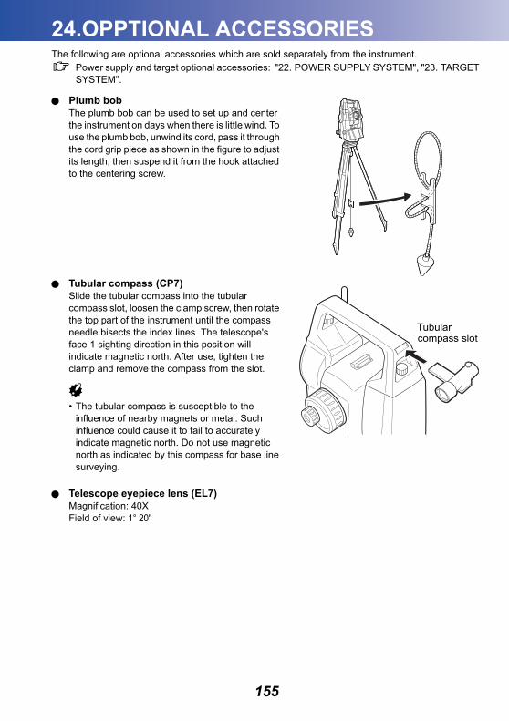
24.OPPTIONAL ACCESSORIES
The following are optional accessories which are sold separately from the instrument.Power supply and target optional accessories: "22. POWER SUPPLY SYSTEM", "23. TARGET SYSTEM".
Plumb bobThe plumb bob can be used to set up and center the instrument on days when there is little wind. To use the plumb bob, unwind its cord, pass it through the cord grip piece as shown in the figure to adjust its length, then suspend it from the hook attached to the centering screw.
Tubular compass (CP7)Slide the tubular compass into the tubular compass slot, loosen the clamp screw, then rotate the top part of the instrument until the compass needle bisects the index lines. The telescope's face 1 sighting direction in this position will indicate magnetic north. After use, tighten the clamp and remove the compass from the slot.
• The tubular compass is susceptible to the influence of nearby magnets or metal. Such influence could cause it to fail to accurately indicate magnetic north. Do not use magnetic north as indicated by this compass for base line surveying.
Telescope eyepiece lens (EL7)Magnification: 40XField of view: 1° 20'
Tubularcompass slot
155
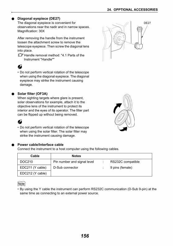
24. OPPTIONAL ACCESSORIES
Diagonal eyepiece (DE27)The diagonal eyepiece is convenient for observations near the nadir and in narrow spaces.Magnification: 30X
After removing the handle from the instrument loosen the attachment screw to remove the telescope eyepiece. Then screw the diagonal lens into place.
Handle removal method: "4.1 Parts of the Instrument "Handle""
• Do not perform vertical rotation of the telescope when using the diagonal eyepiece. The diagonal eyepiece may strike the instrument causing damage.
Solar filter (OF3A)When sighting targets where glare is present, solar observations for example, attach it to the objective lens of the instrument to protect its interior and the eyes of its operator. The filter part can be flipped up without being removed.
• Do not perform vertical rotation of the telescope when using the solar filter. The solar filter may strike the instrument causing damage.
Power cable/Interface cableConnect the instrument to a host computer using the following cables.
• By using the Y cable the instrument can perform RS232C communication (D-Sub 9-pin) at the same time as connecting to an external power source.
Cable Notes
DOC210 Pin number and signal level : RS232C compatible
EDC211 (Y cable) D-Sub connector : 9 pins (female)
EDC212 (Y cable)
DE27
156
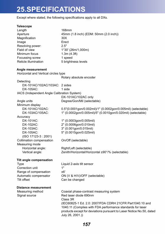
25.SPECIFICATIONS
Except where stated, the following specifications apply to all DXs.TelescopeLength 168mmAperture 45mm (1.8 inch) (EDM: 50mm (2.0 inch))Magnification 30XImage ErectResolving power: 2.5" Field of view 1°30' (26m/1,000m)Minimum focus 1.3m (4.3ft)Focussing screw 1 speedReticle illumination 5 brightness levels
Angle measurementHorizontal and Vertical circles type
Rotary absolute encoderDetecting
DX-101AC/102AC/103AC: 2 sidesDX-105AC: 1 side
IACS (Independent Angle Calibration System)DX-101AC/102AC only
Angle units Degree/Gon/Mil (selectable)Minimum display
DX-101AC/102AC: 0.5"(0.0001gon/0.002mil)/1" (0.0002gon/0.005mil) (selectable)DX-103AC/105AC: 1" (0.0002gon/0.005mil)/5" (0.0010gon/0.020mil) (selectable)
AccuracyDX-101AC: 1" (0.0003gon/0.005mil)DX-102AC: 2" (0.0006gon/0.010mil) DX-103AC: 3" (0.001gon/0.015mil) DX-105AC: 5" (0.0015gon/0.025mil) (ISO 17123-3 : 2001)
Collimation compensation On/Off (selectable)Measuring mode
Horizontal angle: Right/Left (selectable)Vertical angle: Zenith/Horizontal/Horizontal ±90°/% (selectable)
Tilt angle compensation Type Liquid 2-axis tilt sensorCorrection unit 1"Range of compensation ±6’Automatic compensator ON (V & H/V)/OFF (selectable)Tilt offset Can be changed
Distance measurementMeasuring method Coaxial phase-contrast measuring systemSignal source Red laser diode 690nm
Class 3R (IEC60825-1 Ed. 2.0: 2007/FDA CDRH 21CFR Part1040.10 and 1040.11 (Complies with FDA performance standards for laser products except for deviations pursuant to Laser Notice No.50, dated July 26, 2001.))
157
25. SPECIFICATIONS
(When the prism or reflective sheet is selected in Config mode as target, the output is equivalent to Class 1)
Measuring range*9 (Using the following reflective prism/reflective sheet target during normal atmospheric conditions*1/ *2 is good atmospheric conditions)
360° Prism ATP1/ATP1S:*2 1.3 to 1,000 m (3,280ft)*3Mini pole prism OR1PA: 1.3 to 500m (1,640ft)*7Compact prism CP01: 1.3 to 2,500m (8,200ft)*7Standard prism AP01AR X 1:
1.3 to 5,000m (16,400ft)*7(to 6,000m) (19,680ft)*7
Standard prism AP01AR X 3: to 8,000 m (26,240ft)*7(10,000m) (32,800ft)*7
Reflective sheet RS90N-K: 1.3 to 500m (1,640ft)*4Reflective sheet RS50N-K: 1.3 to 300m (980ft)*4Reflective sheet RS10N-K: 1.3 to 100m (320ft)*4
Reflectorless (White) : 0.3 to 800m (2,620ft)*5(to 1,000m) (3,280ft)*6
Prism (tracking)*3 :1.3 to 1,000m (3,280ft)Refrective sheet target (tracking)*4
:1.3 to 350m (1,140ft)Reflectorless (White) (tracking)*5
:0.3 to 300m (980 ft)Minimum display
Fine measurement: 0.0001m (0.001ft/ 1/16 inch)/0.001 m (0.005ft/ 1/8 inch)Rapid measurement: 0.001 m (0.005ft/ 1/8 inch)Tracking measurement: 0.01 m (0.1ft/ 1/2 inch)
Maximum slope distance display (Except for tracking)12,000.000m (39,370ft) (using prism or reflective sheet target)1,200.000m (3,930ft) (Reflectorless)
Distance unit m/ft/inch (selectable)Accuracy (D: measurement distance; Unit: mm) (Under normal atmospheric conditions*1)*7, *9
(Using prism or using 360° Prism ATP1/ATP1S*3)Fine measurement: (1.5 + 2 ppm X D) mmRapid measurement: (5 + 2 ppm X D) mm
(Using reflective sheet target)*4Fine measurement: (2 + 2 ppm X D) mmRapid measurement: (5 + 2 ppm X D) mm
(Reflectorless (White))*5Fine measurement:(2 + 2ppm X D) mm (0.3 to 200m)*8(5 + 10ppm X D) mm (over 200 to 350m)(10 + 10ppm X D) mm (over 350 to 1,000m)Rapid measurement:(6 + 2ppm X D) mm (0.3 to 200m)(8 + 10ppm X D) mm (over 200 to 350m)(15 + 10ppm X D) mm (over 350 to 1,000m)
(ISO 17123-4 : 2001)Measurement mode Fine measurement (single/repeat/average)/Rapid measurement
(single/repeat)/Tracking (selectable)
158
25. SPECIFICATIONS
Measuring time (fastest time under good atmospheric conditions*2, no compensation, EDM ALC at appropriate setting, slope distance)
Fine measurement: less than 1.5 sec + every 0.9 sec or lessRapid measurement: less than 1.3 sec + every 0.6 sec or lessTracking measurement: less than 1.3 sec + every 0.4 sec or less
Atmospheric correctionTemperature input range: - 30 to 60°C (in 0.1°C step)/ - 22 to 140°F (in 1°F step)Pressure input range: 500 to 1,400 hPa (in 1hPa step)
375 to 1,050 mmHg (in 1mmHg step)14.8 to 41.3 inchHg (in 0.1inchHg step)
ppm input range: -499 to 499 ppm (in 1 ppm step)Prism constant correction -99 to 99 mm (in 1 mm step)
0mm fixed for reflectorless measurementEarth curvature and refraction correction
No/Yes K=0.142/Yes K=0.20 (selectable)Sea level correction No/Yes (selectable)
*1 : Slight haze, visibility about 20 km, sunny periods, weak scintillation.*2 : No haze, visibility about 40 km, overcast, no scintillation.*3 : Figures when both the elevation and depression angles of the laser beam are within 15° and
the instrument is facing the 360° Prism.*4 : Figures when the laser beam strikes within 30° of the reflective sheet target.*5 : Figures when using Kodak Gray Card White side (reflection factor 90%) and brightness level
is less than 5,000 lx.*6 : Figures when using Kodak Gray Card White side (reflection factor 90%) and brightness level
is less than 500 lx.*7 : Face the target toward the prism during the measurement with the distance at 10 m or less.*8 : Accuracy is (5 + 2 ppm X D) mm for distance range 0.3 to 0.66m.*9 : Figures will change depending on the target reflection factor, weather conditions and location
conditions.
159
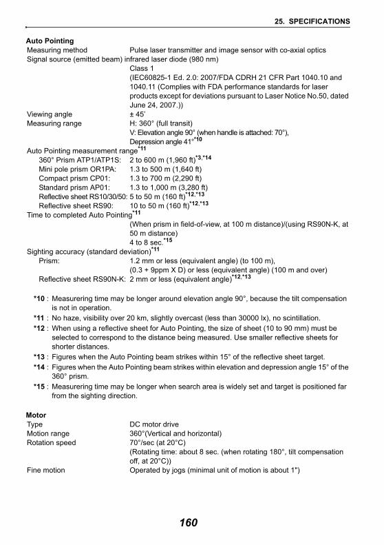
25. SPECIFICATIONS
Auto PointingMeasuring method Pulse laser transmitter and image sensor with co-axial opticsSignal source (emitted beam) infrared laser diode (980 nm)
Class 1(IEC60825-1 Ed. 2.0: 2007/FDA CDRH 21 CFR Part 1040.10 and 1040.11 (Complies with FDA performance standards for laser products except for deviations pursuant to Laser Notice No.50, dated June 24, 2007.))
Viewing angle ± 45’Measuring range H: 360° (full transit)
V: Elevation angle 90° (when handle is attached: 70°), Depression angle 41°*10
Auto Pointing measurement range*11
360° Prism ATP1/ATP1S: 2 to 600 m (1,960 ft)*3,*14
Mini pole prism OR1PA: 1.3 to 500 m (1,640 ft)Compact prism CP01: 1.3 to 700 m (2,290 ft)Standard prism AP01: 1.3 to 1,000 m (3,280 ft)Reflective sheet RS10/30/50: 5 to 50 m (160 ft)*12,*13
Reflective sheet RS90: 10 to 50 m (160 ft)*12,*13
Time to completed Auto Pointing*11 (When prism in field-of-view, at 100 m distance)/(using RS90N-K, at 50 m distance)4 to 8 sec.*15
Sighting accuracy (standard deviation)*11
Prism: 1.2 mm or less (equivalent angle) (to 100 m),(0.3 + 9ppm X D) or less (equivalent angle) (100 m and over)
Reflective sheet RS90N-K: 2 mm or less (equivalent angle)*12,*13
*10 : Measurering time may be longer around elevation angle 90°, because the tilt compensation is not in operation.
*11 : No haze, visibility over 20 km, slightly overcast (less than 30000 lx), no scintillation.*12 : When using a reflective sheet for Auto Pointing, the size of sheet (10 to 90 mm) must be
selected to correspond to the distance being measured. Use smaller reflective sheets for shorter distances.
*13 : Figures when the Auto Pointing beam strikes within 15° of the reflective sheet target.*14 : Figures when the Auto Pointing beam strikes within elevation and depression angle 15° of the
360° prism.*15 : Measurering time may be longer when search area is widely set and target is positioned far
from the sighting direction.
MotorType DC motor drive Motion range 360°(Vertical and horizontal)Rotation speed 70°/sec (at 20°C)
(Rotating time: about 8 sec. (when rotating 180°, tilt compensation off, at 20°C))
Fine motion Operated by jogs (minimal unit of motion is about 1")
160
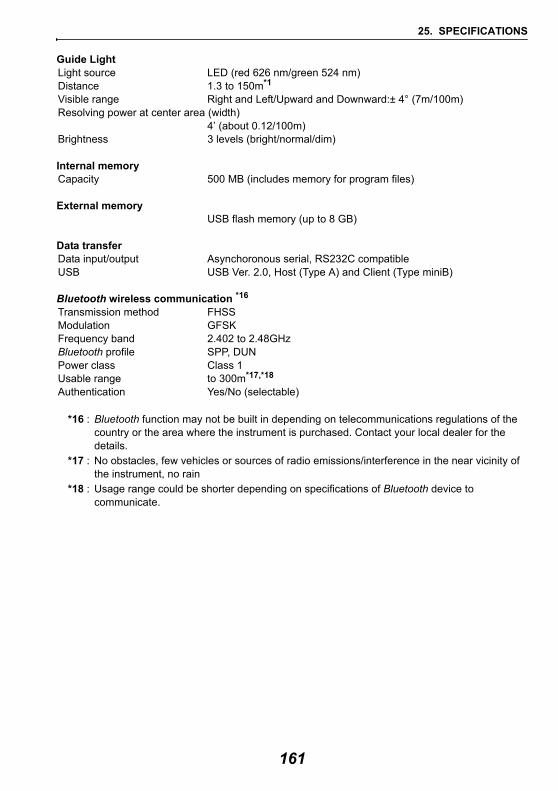
25. SPECIFICATIONS
Guide LightLight source LED (red 626 nm/green 524 nm) Distance 1.3 to 150m*1
Visible range Right and Left/Upward and Downward:± 4° (7m/100m)Resolving power at center area (width)
4’ (about 0.12/100m)Brightness 3 levels (bright/normal/dim)
Internal memoryCapacity 500 MB (includes memory for program files)
External memoryUSB flash memory (up to 8 GB)
Data transferData input/output Asynchoronous serial, RS232C compatibleUSB USB Ver. 2.0, Host (Type A) and Client (Type miniB)
Bluetooth wireless communication *16
Transmission method FHSS Modulation GFSKFrequency band 2.402 to 2.48GHzBluetooth profile SPP, DUNPower class Class 1Usable range to 300m*17,*18
Authentication Yes/No (selectable)
*16 : Bluetooth function may not be built in depending on telecommunications regulations of the country or the area where the instrument is purchased. Contact your local dealer for the details.
*17 : No obstacles, few vehicles or sources of radio emissions/interference in the near vicinity of the instrument, no rain
*18 : Usage range could be shorter depending on specifications of Bluetooth device to communicate.
161
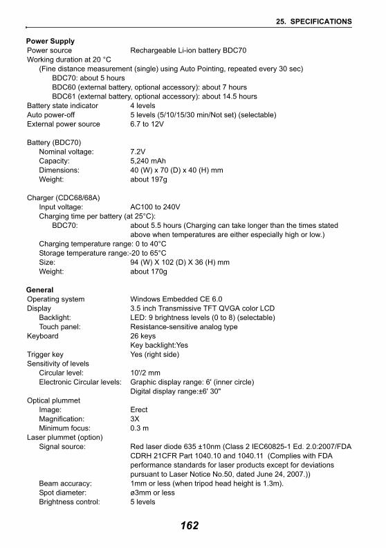
25. SPECIFICATIONS
Power SupplyPower source Rechargeable Li-ion battery BDC70 Working duration at 20 °C
(Fine distance measurement (single) using Auto Pointing, repeated every 30 sec)BDC70: about 5 hoursBDC60 (external battery, optional accessory): about 7 hoursBDC61 (external battery, optional accessory): about 14.5 hours
Battery state indicator 4 levels Auto power-off 5 levels (5/10/15/30 min/Not set) (selectable)External power source 6.7 to 12V
Battery (BDC70)Nominal voltage: 7.2VCapacity: 5,240 mAhDimensions: 40 (W) x 70 (D) x 40 (H) mmWeight: about 197g
Charger (CDC68/68A)Input voltage: AC100 to 240VCharging time per battery (at 25°C):
BDC70: about 5.5 hours (Charging can take longer than the times stated above when temperatures are either especially high or low.)
Charging temperature range: 0 to 40°CStorage temperature range:-20 to 65°CSize: 94 (W) X 102 (D) X 36 (H) mmWeight: about 170g
GeneralOperating system Windows Embedded CE 6.0Display 3.5 inch Transmissive TFT QVGA color LCD
Backlight: LED: 9 brightness levels (0 to 8) (selectable)Touch panel: Resistance-sensitive analog type
Keyboard 26 keysKey backlight:Yes
Trigger key Yes (right side)Sensitivity of levels
Circular level: 10'/2 mmElectronic Circular levels: Graphic display range: 6' (inner circle)
Digital display range:±6' 30"Optical plummet
Image: ErectMagnification: 3XMinimum focus: 0.3 m
Laser plummet (option)Signal source: Red laser diode 635 ±10nm (Class 2 IEC60825-1 Ed. 2.0:2007/FDA
CDRH 21CFR Part 1040.10 and 1040.11 (Complies with FDA performance standards for laser products except for deviations pursuant to Laser Notice No.50, dated June 24, 2007.))
Beam accuracy: 1mm or less (when tripod head height is 1.3m).Spot diameter: ø3mm or lessBrightness control: 5 levels
162

25. SPECIFICATIONS
Auto power-off: Provided (power cut off after 5 minutes)Calendar/clock function YesLaser-pointer function ON/OFF (selectable)Operating temperature: -20 to 50 °C (-4 to 122 °F) Storage temperature range -30 to 60°C (-22 to 140 °F) (no condensation)Dust and water resistance IP65 (IEC 60529:2001)Instrument height: 196 mm from tribrach mounting surfaceSize (with handle):
Display on one side: 207 (W) X 174 (D) X 372 (H) mmDisplay on both sides: 207 (W) X 190 (D) X 372 (H) mm
(when using tribrach TR-101, except for projections)Weight 6.1kg (13.4lb)
(with BDC70 and tribrach)
163
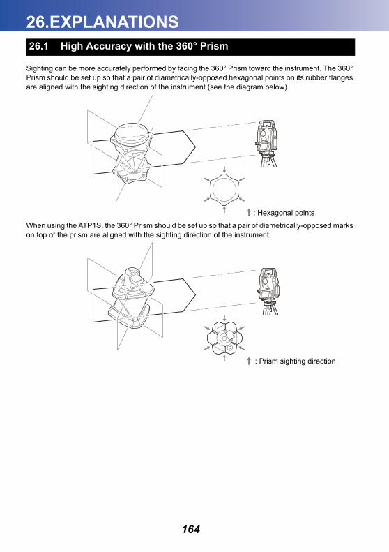
26.EXPLANATIONS
Sighting can be more accurately performed by facing the 360° Prism toward the instrument. The 360° Prism should be set up so that a pair of diametrically-opposed hexagonal points on its rubber flanges are aligned with the sighting direction of the instrument (see the diagram below).
When using the ATP1S, the 360° Prism should be set up so that a pair of diametrically-opposed marks on top of the prism are aligned with the sighting direction of the instrument.
26.1 High Accuracy with the 360° Prism
: Hexagonal points
: Prism sighting direction
164
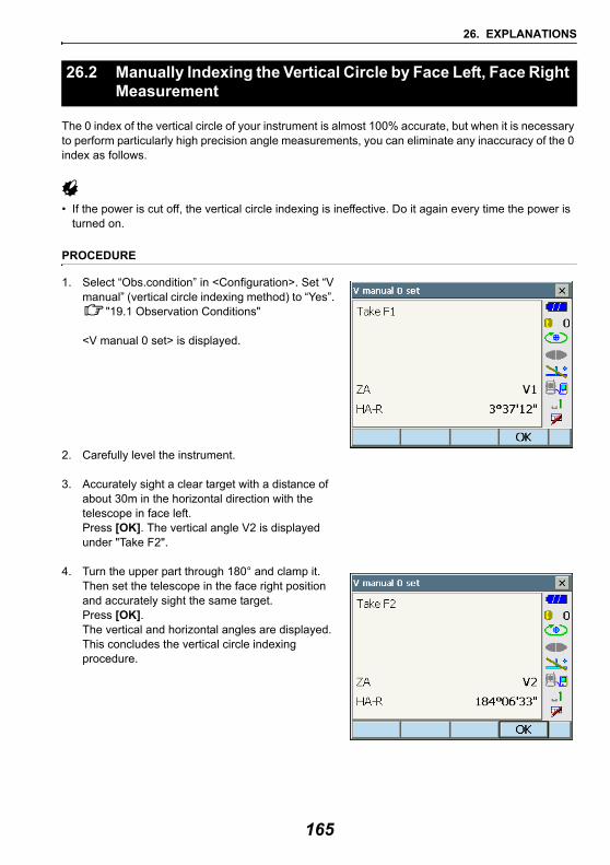
26. EXPLANATIONS
The 0 index of the vertical circle of your instrument is almost 100% accurate, but when it is necessary to perform particularly high precision angle measurements, you can eliminate any inaccuracy of the 0 index as follows.
• If the power is cut off, the vertical circle indexing is ineffective. Do it again every time the power is turned on.
PROCEDURE
1. Select “Obs.condition” in <Configuration>. Set “V manual” (vertical circle indexing method) to “Yes”.
"19.1 Observation Conditions"
<V manual 0 set> is displayed.
2. Carefully level the instrument.
3. Accurately sight a clear target with a distance of about 30m in the horizontal direction with the telescope in face left.Press [OK]. The vertical angle V2 is displayed under "Take F2".
4. Turn the upper part through 180° and clamp it. Then set the telescope in the face right position and accurately sight the same target. Press [OK]. The vertical and horizontal angles are displayed. This concludes the vertical circle indexing procedure.
26.2 Manually Indexing the Vertical Circle by Face Left, Face Right Measurement
165
27.REGULATIONS
Region/CountryDirectives/ Regulations Labels/Declarations
U.S.A. FCC-Class A FCC ComplianceWARNING:Changes or modifications to this unit not expressly approved by the party responsible for compliance could void the user's authority to operate the equipment.
NOTE:This equipment has been tested and found to comply with the limits for a Class A digital device pursuant to Part 15 of the FCC Rules. These limits are designed to provide reasonable protection against harmful inter-ference when the equipment is operated in a commercial environment. This equipment generates, uses, and can radiate radio frequency energy and, if not installed and used in accordance with the operator’s manual, may cause harmful interference to radio communications. Operation of this equipment in a residential area is likely to cause harmful interference in which case the user will be required to correct the interference at his own expense.
Means of conformityThis device complies with part 15 of the FCC Rules, Operation is subject to the following two conditions: (1) This device may not cause harmful interference, and (2) this device must accept any interference received, including interference that may cause undesired operation.
This transmitter must not be co-located or operated in conjunction with any other antenna or transmitter.
This equipment complies with FCC radiation exposure limits set forth for uncontrolled equipment and meets the FCC radio frequency (RF) Exposure Guidelines in Supplement C to OET65. This equipment has very low levels of RF energy that is deemed to comply without maximum permissive exposure evaluation (MPE). But it is desirable that it should be installed and operated with at least 20cm and more between the radiator and person’s body (excluding extremeties: hands, wrists, feet and ankles).Declaration of Conformity
Model Number: DX seriesTrade Name: TOPCON CORPORATION
ManufactureName: TOPCON CORPORATIONAddress: 75-1, Hasunuma-cho, Itabashi-ku, Tokyo,
174-8580 JAPANCountry: JAPAN
U.S.A. RepresentativeResponsible party: TOPCON POSITIONING SYSTEMS,INC.Address 7400 National Drive Livermore, CA94551, U.S.ATelephone number: 925-245-8300
166
27. REGULATIONS
California, U.S.A.
Proposition 65
California, U.S.A
Perchlorate Material(CR Lithium Battery)
California and NY, U.S.A.
RecyclingBatteries
Region/Country
Directives/ Regulations Labels/Declarations
167
27. REGULATIONS
Canada ICES-Class A This Class A digital apparatus meets all requirements of Canadian Interference-Causing Equipment Regulations.Cet appareil numérique de la Class A respecte toutes les exigences du Règlement sur le matériel brouilleur du Canada.
This class A digital apparatus complies with Canadian ICES-003.Cet appareil numerique de la classe A est conforme a la norme NMB-003 du Canada.
Operation is subject to the following two conditions: (1) this device may not cause interference, and (2) this device must accept any interference, including interference that may cause undesired operation of this device.
This equipment complies with IC radiation exposure limits set forth for uncontrolled equipment and meets RSS-102 of the IC radio frequency (RF) Exposure rules. This equipment should be installed and operated with at least 20cm and more between the radiator and person’s body (excluding extremeties: hands, wrists, feet and ankles).
EU EMC-Class BR&TTE-Class 2
EU R&TTE-Class 2
R&TTE Directive
DX seriesHereby, TOPCON CORP., declares that the above-mentioned equipment is in compliance with the essential requirements and other relevant provisions of Directive 1999/5/EC.
Please inquire below if you wish to receive a copy of Topcon's Declaration of Conformity.
Topcon Europe Positioning B.V.Essebaan 11, 2908 LJ Capelle a/d IJssel, The NetherlandsTel:+31-10-4585077 Fax:+31-10-2844949http://www.topcon-positioning.eu/
Region/Country
Directives/ Regulations Labels/Declarations
168
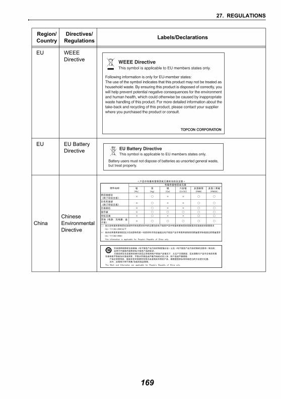
27. REGULATIONS
EU WEEE Directive
EU EU Battery Directive
ChinaChinese Environmental Directive
Region/Country
Directives/ Regulations Labels/Declarations
169
28.INDEX
AACK mode ..................................................................................................................................44Adjusting backlight brightness/turning the reticle illumination and key backlight ON/OFF .......116Atmospheric correction factor ...................................................................................................119AUTO AIM ..................................................................................................................................54Automatic tilt angle compensation mechanism ........................................................................113
BBluetooth connections ................................................................................................................43Bluetooth device address ...........................................................................................................46
CCold boot ....................................................................................................................................41Collimation correction ...............................................................................................................114Color setting .............................................................................................................................117
DDate and Time ..........................................................................................................................133
EEDM ALC .................................................................................................................................117Eliminating parallax ....................................................................................................................57
FFixed velocity rotation .................................................................................................................62
GGuide light ..................................................................................................................................11
HHdist .........................................................................................................................................113Horizontal angle settings ......................................................................................................74, 80Horizontal jog .............................................................................................................................12
IInch (Fraction of an inch) ..........................................................................................................131Instrument height mark ...............................................................................................................11
KKey backlight ............................................................................................................................117
LLaser-pointer function .................................................................................................................11Laser-pointer off .......................................................................................................................117
PPower-saving automatic cut-off/Backlight Off ...........................................................................116Precaution when performing resection .......................................................................................85Prism constant correction value ...............................................................................................118Problems Powering OFF ............................................................................................................42Power-saving automatic cut-off (Power on command) .............................................................116
RResection calculation process ....................................................................................................84Resume function ........................................................................................................................40
SSea level correction ..................................................................................................................114Search operation during Auto pointing .......................................................................................55Sighting collimator ......................................................................................................................12Sighting manually .......................................................................................................................58Slope area ................................................................................................................................108
TTerminate ...................................................................................................................................44
170

28. INDEX
Trigger key ................................................................................................................................. 12TURN ......................................................................................................................................... 55
VV mode (vertical angle display method) ................................................................................... 114Vertical Jog ................................................................................................................................ 12
171

http://www.topcon.co.jp
GLOBAL GATEWAY http://global.topcon.com/Please see the attached address list or the following website for contact addresses.
©2013 TOPCON CORPORATIONALL RIGHTS RESERVED