Embed Size (px)
Citation preview

DVR SMART MOTOR FOR RIKON 14” BANDSAWS
Instruction Manual
SKU 13-926
www.striatech.com www.rikontools.com

1 © 2018 Striatech. All rights reserved.
BENEFITS OF STRIATECH
STRIATECH ELECTRONIC DRIVE
The Striatech Digital Variable Reluctance motor (DVR) motor is a unique variable speed motor. The Striatech motor uses smart motor technology to provide an incredibly smooth and powerful drive. The controller monitors the spindle position constantly and maintains spindle speed very closely. Additional power is added as it senses extra load from the application. The motor is virtually maintenance free and designed with high reliability.
BENEFITS OF THE DVR PACKAGE DRIVE MOTOR
▪ Intelligence Controlled by a micro-processor the motor can save and store speed information on different settings and switch from one to another immediately.
▪ 16 Selectable Favorite Speeds Four x four function pre-programmed buttons for each cutting material application including one custom speed range.
▪ Adaptive Control Software Smart adaptive computer technology actually measures the weight of the work piece and adjusts its performance accordingly.
▪ Safety Sensing Feature Intelligent DVR computer controller can sense abnormal operational conditions e.g. sudden increases of load - it can instantaneously shut down power to the motor. Normal safety precautions would still apply.
▪ Energy Efficient Unlike other ‘dumb’ electric motors, the Smart DVR Motor only inputs enough power to maintain the set speed – giving you potential for up to 50% power savings over conventional motors.
▪ Wide Speed Range 100-2,160 motor rpm*, easy dial speed change. *Motor RPM range has been limited for safe use on bandsaws.
▪ Direct Drive Motor Driven by unique Digital Variable Reluctance Motor Technology, with superior performance over AC or DC motors. Proven technology, with many thousands of users. Provides digital electronic dial variable speed with no belt changes.
▪ Warranties 2 Year Warranty on all electronics and electrical components. 5 Year Warranty on motor.
▪ Low Maintenance The motor is simple, brushless with no rotor windings (rotor is solid steel). The industrial grade electronics are built to last. Need technical help? Please call us at (727)-202-9932 if you have any questions.

2 © 2018 Striatech. All rights reserved.
GENERAL SAFETY RULES
GENERAL SAFETY RULES
WARNING! Failure to follow these rules may result in serious personal injury.
1. FOR YOUR OWN SAFETY, READ THE MANUAL BEFORE OPERATING THE TOOL. Learn the machine’s application and limitations plus the specific hazards particular to it.
2. ALWAYS WEAR SAFETY GLASSES OR USE A FULL-FACE SHIELD. Everyday eyeglasses that are impact resistant and safety glasses are strongly recommended to protect eyes (must comply with ANSI STANDARD Z87.1 - USA). Use a full-face shield to protect eyes and face. In addition, use face or dust mask if cutting operation is dusty.
3. WEAR PROPER APPAREL. Do not wear loose clothing, gloves, neckties, rings, bracelets or other jewelry which may get caught in moving parts. Non-slip footwear is recommended. Wear protective hair covering to contain long hair.
4. USE EAR PROTECTION. Use ear muffs or foam earplugs for extended periods of operation. Use muffs rated to 103 dBA Leq (8 hour).
5. DON’T USE IN DANGEROUS ENVIRONMENT. Don’t use power tools in damp or wet locations or expose to rain. Keep work area well lighted. The Striatech motor and RIKON Bandsaw are intended for indoor use only. Failure to do so may void the warranty.
6. KEEP WORK AREA CLEAN. Cluttered areas and benches invite accidents. Buildup of sawdust is a fire hazard.
7. KEEP CHILDREN AND VISITORS AWAY. The Striatech motor and RIKON Bandsaw are not recommended for children. Onlookers should be kept a safe distance from work area.
8. MAKE WORKSHOP CHILDPROOF with locks, master switches, or by removing starter keys.
9. GROUND ALL TOOLS. If the tool is equipped with a three-prong plug, it should be plugged into a three-hole electrical receptacle. If an adapter is used to accommodate a two-prong receptacle, the adapter plug must be attached to a known ground. Never remove the third prong.
10. MAKE SURE TOOL IS DISCONNECTED FROM POWER SUPPLY while the motor is being mounted, connected, or re- connected.
11. DISCONNECT CONTROLLER FROM WALL SOCKET before servicing and when changing accessories such as blade, screws, fuses, etc.
12. AVOID ACCIDENTIAL STARTING. Make sure switch is in the Off position before plugging in power cord.
13. NEVER LEAVE MACHINE RUNNING UNATTENDED. Do not leave machine unless it is turned off and has come to a complete stop.
14. KEEP GUARDS IN PLACE and in working order. 15. USE CORRECT TOOLS. Do not use a tool or attachment
to do a job for which it was not designed. 16. USE RECOMMENDED ACCESSORIES. The use of
improper accessories may cause hazards. 17. DON’T FORCE THE TOOL. It will do the job better and
be safer at the rate for which it was designed. 18. MAINTAIN TOOLS IN TOP CONDITION. Keep tools
sharp and clean for best and safest performance. Follow instructions for lubricating and changing accessories.
19. NEVER STAND ON TOOL. Serious injury could occur if the tool is tipped or if the cutting tool is accidentally contacted.
20. DON’T OVERREACH. Keep proper footing and balance at all times.
21. DIRECTION OF FEED. Feed work into the blade against the rotation of the blade teeth only.
22. ATTENTION TO WORK. Concentrate on your work. If you become tired or frustrated, leave it for a while and rest.
23. SECURE WORK. Use jig or push stick supplied with bandsaw to hold work when practical. Otherwise, use clamps or jigs to secure the workpiece. It’s safer than using your hand and frees both hands to operate tool.
24. CHECK DAMAGED PARTS. Before further use of the tool, carefully inspect for any damaged parts to ensure that it will operate properly and perform its intended function. Check for alignment of moving parts, binding of moving parts, mounting and any other conditions that may affect its operation. Any damaged part should be properly repaired or replaced.
25. DRUGS, ALCOHOL, MEDICATION. Do not operate machine while under the influence of drugs, alcohol, or any medication.
26. DUST WARNING. The dust generated by materials can be harmful to your health. Always operate machinery in well-ventilated areas and provide means for proper dust removal. Use wood dust collection systems whenever possible.

3 © 2018 Striatech. All rights reserved.
INSTALLING THE STRIATECH PACKAGE DRIVE
INSTALLING STRIATECH PACKAGE DRIVE ON THE RIKON 10-324 & 10-326 BANDSAWS NOTE: 10-326DVR Owners can skip sections 1 thru 9 and proceed directly to section 10 on page six.
Tools Needed: 1 x Phillips Screwdriver 1 x Flat Blade Screwdriver (optional) 1 x Wire Cutters (optional) 1 x Ratchet Wrench (with 10mm socket & extension) 1 x 3mm Allen Key (supplied with Bandsaw) 1 x 4mm Allen Key (supplied with Bandsaw) 1 x 5mm Allen Key (supplied with Bandsaw) 1 x 6mm Allen Key (supplied with Bandsaw)
1. The 1st step for this process is to unplug the machine from the electrical supply. This ensures that the Bandsaw will not accidentally turn on if the ON/OFF switch is bumped when changing the motor.
4 © 2018 Striatech. All rights reserved.
INSTALLING THE STRIATECH PACKAGE DRIVE
2. Open the bottom wheel door. Release the blade tension by moving the Quick Release Lever from right to left. Remove the saw blade from the bandsaw (refer to bandsaw manual for instructions). Loosen the belt tensioning handwheel and remove the belt from the lower wheel and motor pulley.
3. With the belt removed, unscrew the socket screw holding the lower wheel and remove from shaft (using a 6mm Allen Key).
4. Remove the 4 Phillips screws holding the ON/OFF switch using a drill or Phillips Screw Driver. Pull the ON/OFF switch to expose the wiring. Unscrew the wiring from the ON/OFF switch. Unscrew and remove the ground wire screw and green ground wire from the frame.

5 © 2018 Striatech. All rights reserved.
INSTALLING THE STRIATECH PACKAGE DRIVE
5. Locate and remove the motor lead wire from the saw column. 10-324 & 10-326 only: Remaining wires will be the power cord and wire to the accessory receptacle. Splice the black, white and green wires together to retain use of the accessory receptacle. Place wires back into column.
6. With assistance; unscrew the 4 bolts holding the motor using a 10mm wrench and remove from bandsaw (TIP: Slide two wood wedge blocks on both sides of the motor for ease of removal). Remove the one (or two) set screws from the motor pulley and slide off shaft. Remove key from motor.
7. Slide key into Striatech motor keyway. Slide motor pulley onto shaft and tighten set screw tightly. With assistance; set the Striatech motor into the hole and slide until bolt holes line up with bandsaw holes (TIP: Slide two wood blocks on both sides of the motor for ease of installation). Screw the 4 bolts tightly.
6 © 2018 Striatech. All rights reserved.
INSTALLING THE STRIATECH PACKAGE DRIVE
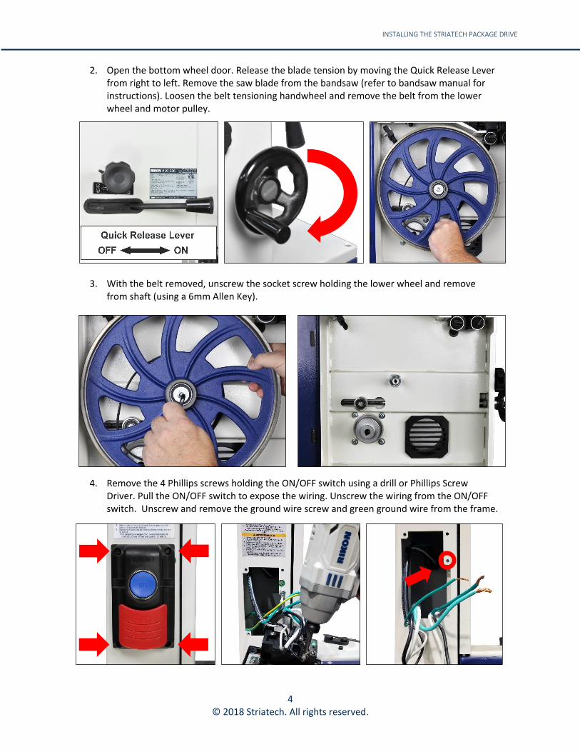
8. Mount the lower wheel and set belt onto the high-speed pulley. Screw wheel in place. Wrap the v-belt around the belt tensioner and motor pulley. Tighten the v-belt using the belt tensioning handwheel until there is 3/8” to ½” deflection (As mentioned in the Operator’s Manual supplied with the unit). NOTE: Check drive belt alignment. Refer to Step 7 to loosen set screw(s). Move motor pulley to correct alignment and tighten the set screw(s).
9. Install the blade that was removed in step 2. Pull the Quick Release Lever to the right to tension the blade on the band wheels (as mentioned in your bandsaw’s operation manual).
10. Install the bracket for the controller on to the bandsaw. NOTE: the bracket on the 10-326DVR is shipped installed inward. Remove and follow next steps. Line up the 4 screw holes on the bracket to the holes on the bandsaw frame. Screw the 4 Phillip screws (removed from the ON/OFF plate in step 4) to hold the bracket in place where the ON/OFF switch was located.
7 © 2018 Striatech. All rights reserved.
INSTALLING THE STRIATECH PACKAGE DRIVE
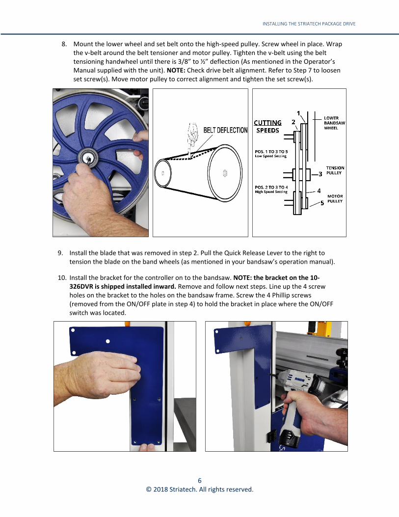
11. Install the controller onto the mounting bracket. Align the 3 holes in the mounting bracket to the holes on the back of the control panel. Using a 5mm Allen Key, screw the three M6 bolts, lock washers and washers to the control panel.
12. Plug the male end of the Molex extension cable to the controller, then connect the female end to the Striatech motor cable.
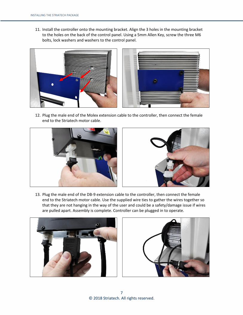
13. Plug the male end of the DB-9 extension cable to the controller, then connect the female end to the Striatech motor cable. Use the supplied wire ties to gather the wires together so that they are not hanging in the way of the user and could be a safety/damage issue if wires are pulled apart. Assembly is complete. Controller can be plugged in to operate.
8 © 2018 Striatech. All rights reserved.
CONTROLLER
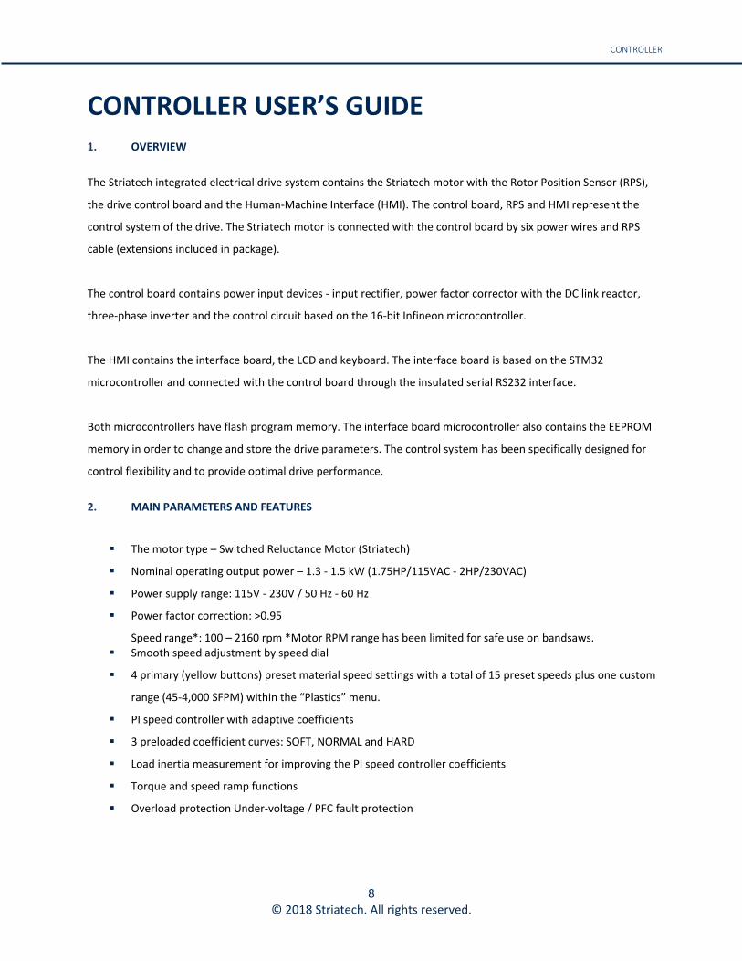
CONTROLLER USER’S GUIDE 1. OVERVIEW
The Striatech integrated electrical drive system contains the Striatech motor with the Rotor Position Sensor (RPS),
the drive control board and the Human-Machine Interface (HMI). The control board, RPS and HMI represent the
control system of the drive. The Striatech motor is connected with the control board by six power wires and RPS
cable (extensions included in package).
The control board contains power input devices - input rectifier, power factor corrector with the DC link reactor,
three-phase inverter and the control circuit based on the 16-bit Infineon microcontroller.
The HMI contains the interface board, the LCD and keyboard. The interface board is based on the STM32
microcontroller and connected with the control board through the insulated serial RS232 interface.
Both microcontrollers have flash program memory. The interface board microcontroller also contains the EEPROM
memory in order to change and store the drive parameters. The control system has been specifically designed for
control flexibility and to provide optimal drive performance.
2. MAIN PARAMETERS AND FEATURES
▪ The motor type – Switched Reluctance Motor (Striatech)
▪ Nominal operating output power – 1.3 - 1.5 kW (1.75HP/115VAC - 2HP/230VAC)
▪ Power supply range: 115V - 230V / 50 Hz - 60 Hz
▪ Power factor correction: >0.95
Speed range*: 100 – 2160 rpm *Motor RPM range has been limited for safe use on bandsaws. ▪ Smooth speed adjustment by speed dial
▪ 4 primary (yellow buttons) preset material speed settings with a total of 15 preset speeds plus one custom
range (45-4,000 SFPM) within the “Plastics” menu.
▪ PI speed controller with adaptive coefficients
▪ 3 preloaded coefficient curves: SOFT, NORMAL and HARD
▪ Load inertia measurement for improving the PI speed controller coefficients
▪ Torque and speed ramp functions
▪ Overload protection Under-voltage / PFC fault protection

9 © 2018 Striatech. All rights reserved.
CONTROLLER
3. HUMAN MACHINE INTERFACE DESCRIPTION
The Human Machine Interface (HMI) provides a flexible choice of the drive parameters:
run/stop, motor speed, direction of rotation, PI speed controller coefficients. HMI contains 2-lines, 16-position LCD
display and keyboard. The drive parameters can be set by decreasing/increasing values incrementally. Some
parameter values can be stored in the EEPROM of HMI.
Figure 1: Keyboard view
4. KEY BOARD DESCRIPTION
Key View Short Description
-Start Key- -run the motor-
-Stop Key- -stop the motor and reset the system-
-Fwd / Reverse* Confirm Key- -*reverse not used for bandsaw configuration-
-Menu Key- -access the menu to set parameters-
-Short Cut Key F1- -quick access to first pre-set speed (For Woods)-
-Short Cut Key F2- -quick access to second pre-set speed (For Metals)-
-Short Cut Key F3- -quick access to third pre-set speed (For Non-Ferrous Metals)-
-Short Cut Key F4- -quick access to fourth pre-set speed (For Plastics & Custom
Speed Range)-
-Rotary Dial- -change speed-

10 © 2018 Striatech. All rights reserved.
CONTROLLER
5. CONNECTING TO POWER
The power cord should be 3-wire, having a grounding conductor and a grounding plug. The plug must be plugged into a matching outlet that is properly installed and grounded in accordance with local electrical codes.
WARNING! Improper connection of the motor can result in a risk of electrical shock. If it is necessary to use an extension cord, the cord should be grounded. Use the correct wire size for the extension cord, for a given cord length, to avoid power loss and over-heating.
IMPORTANT: A Surge Protection Device rated to at least 15 amps - for USA and Canada, other countries 10 or
15 amps - must be used to protect the DVR electronics from electrical spikes or surges, similar to those used on most Home PC’s. Ground Fault Interrupters (GFI’s) or Residual Current Detectors (RCD’s) are helpful and are a recommended protection device for any power tool. Note some makes of GFI may not be compatible.
6. PREPARING THE MOTOR AND CONTROLLER
The motor connects to the controller, so only one power cable is necessary. To connect the motor to the controller, the Molex Connector and the DB-9 Connector must be attached. The Molex Connector is located on the left and only needs to be plugged in (see Fig. 1.1 - 1.2). The DB-9 Connector is located on the right and needs to be tightened in place with a small flat head screw driver (see. 1.3).
Fig. 1.1: Unconnected Molex Connector Fig. 1.2: Connecting Molex Connector Fig. 1.3: Connecting DB-9 Connector
The motor controller is fully connected to the motor once both, the Molex Connector as well as the DB-9 Connector are attached (see Fig. 1.4).
Fig. 1.4: Molex and DB-9 Connector Connected

11 © 2018 Striatech. All rights reserved.
Blade & Motor speed
Current Profile
Motor Speed Limit Exceeded Warning
Shortcut Keys 1 thru 4
USER INTERFACE / PRESET SPEEDS
7. USER INTERFACE
Fig. 2.1: Main Screen
Plug in and turn on the Striatech controller by pressing the Main red rocker switch on the right side of the
controller. Refer to “CONTROLLER BREAKDOWN) on page sixteen. The screen will boot up displaying the “RIKON”
logo, then display the main screen (See Fig. 2.1).
▪ Blade & Motor Speed: Displays blade speed in Feed Per Minute (FPM) & motor speed in Revolutions Per
Minute (RPM)
▪ Current Profile: Displays selected profile for cutting application or specified material
▪ Motor Speed Limit Exceeded Warning: Icon displayed when motor speed exceeds or below recommended
blade speed (Only displayed with improper pulley adjustment)
▪ Shortcut Keys: Displays profile selections for each material
8. PRESET SPEEDS
The Striatech controller comes equipped with several preset speeds, associated with the F1 - F4 keys. To select a
profile, press the corresponding F key until the desired profile appears. For example, if you wish to select the
“Stainless Steel” option, simply press the F2 key until Stainless appears on the screen. The correct Blade Speed
(FPM) will be set, a new minimum and maximum speed limit will be set depending on the profile. The speed can
be adjusted using the Speed Knob to further increase or decrease the cutting speed.
Note: The motor speed is calculated using the Motor Pulley Position (“M.Pulley” in the menu) parameter in the
menu, therefore you must make sure this parameter (HIGH/LOW) match the actual pulley position on your
machine.
12 © 2018 Striatech. All rights reserved.
PRESET SPEEDS / SPEED ADJUSTMENTS
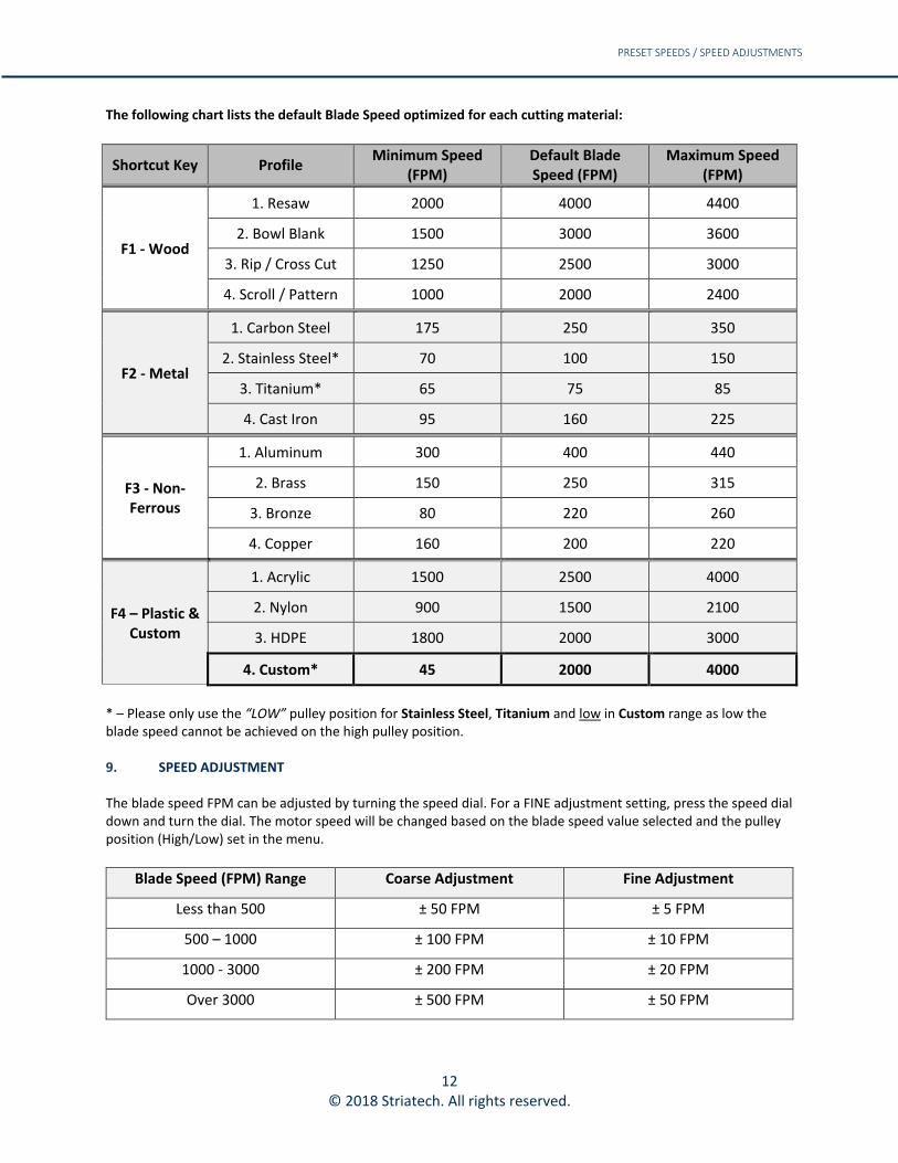
The following chart lists the default Blade Speed optimized for each cutting material:
Shortcut Key Profile Minimum Speed
(FPM) Default Blade Speed (FPM)
Maximum Speed (FPM)
F1 - Wood
1. Resaw 2000 4000 4400
2. Bowl Blank 1500 3000 3600
3. Rip / Cross Cut 1250 2500 3000
4. Scroll / Pattern 1000 2000 2400
F2 - Metal
1. Carbon Steel 175 250 350
2. Stainless Steel* 70 100 150
3. Titanium* 65 75 85
4. Cast Iron 95 160 225
F3 - Non-Ferrous
1. Aluminum 300 400 440
2. Brass 150 250 315
3. Bronze 80 220 260
4. Copper 160 200 220
F4 – Plastic & Custom
1. Acrylic 1500 2500 4000
2. Nylon 900 1500 2100
3. HDPE 1800 2000 3000
4. Custom* 45 2000 4000
* – Please only use the “LOW” pulley position for Stainless Steel, Titanium and low in Custom range as low the blade speed cannot be achieved on the high pulley position. 9. SPEED ADJUSTMENT The blade speed FPM can be adjusted by turning the speed dial. For a FINE adjustment setting, press the speed dial down and turn the dial. The motor speed will be changed based on the blade speed value selected and the pulley position (High/Low) set in the menu.
Blade Speed (FPM) Range Coarse Adjustment Fine Adjustment
Less than 500 ± 50 FPM ± 5 FPM
500 – 1000 ± 100 FPM ± 10 FPM
1000 - 3000 ± 200 FPM ± 20 FPM
Over 3000 ± 500 FPM ± 50 FPM
13 © 2018 Striatech. All rights reserved.
MENU
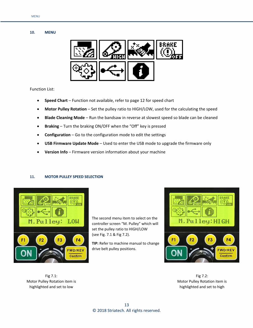
10. MENU
Function List:
• Speed Chart – Function not available, refer to page 12 for speed chart
• Motor Pulley Rotation – Set the pulley ratio to HIGH/LOW, used for the calculating the speed
• Blade Cleaning Mode – Run the bandsaw in reverse at slowest speed so blade can be cleaned
• Braking – Turn the braking ON/OFF when the “Off” key is pressed
• Configuration – Go to the configuration mode to edit the settings
• USB Firmware Update Mode – Used to enter the USB mode to upgrade the firmware only
• Version Info – Firmware version information about your machine
11. MOTOR PULLEY SPEED SELECTION
The second menu item to select on the
controller screen “M. Pulley” which will
set the pulley ratio to HIGH/LOW
(see Fig. 7.1 & Fig 7.2).
TIP: Refer to machine manual to change
drive belt pulley positions.
Fig 7.1:
Motor Pulley Rotation item is
highlighted and set to low
Fig 7.2:
Motor Pulley Rotation item is
highlighted and set to high

14 © 2018 Striatech. All rights reserved.
BLADE CLEANING / VERSION INFORMATION
12. BLADE CLEANING
13. VERSION INFORMATION
The final menu item to select on the
controller screen “Version Information”
(see Fig. 9.1) which informs you about
the version number of your HMI board
(see Fig 9.2).
The third menu item to select on the
controller screen “Blade Cleaning”
(see Fig. 8.1) which will run the bandsaw
in reverse at the slowest speed, so the
blade can be cleaned (see Fig 8.2).
TIP: Use a soft bristle or wire brush to
clean the blade.
Caution: Use a long handle brush and
keep hands a safe working distance from
the blade.
TIP: If the blade is unable to be cleaned
entirely due to pitch build-up, remove
blade from saw and use a blade cleaning
solvent.
Fig 8.1: Blade Cleaning item highlighted
Fig 8.2: Blade Cleaning item selected
Fig 9.1: Version Info item highlighted
Fig 9.2: HMI board info
15 © 2018 Striatech. All rights reserved.
THERMAL RESET SWITCH
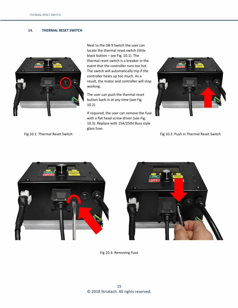
14. THERMAL RESET SWITCH
Next to the DB 9 Switch the user can
locate the thermal reset switch (little
black button – see Fig. 10.1). The
thermal reset switch is a breaker in the
event that the controller runs too hot.
The switch will automatically trip if the
controller heats up too much. As a
result, the motor and controller will stop
working.
The user can push the thermal reset
button back in at any time (see Fig.
10.2).
If required, the user can remove the fuse
with a flat head screw driver (see Fig.
10.3). Replace with 15A/250V Buss style
glass fuse.
Fig 10.1: Thermal Reset Switch
Fig 10.2: Push in Thermal Reset Switch
Fig 10.3: Removing Fuse

16 © 2018 Striatech. All rights reserved.
1
2
EXPLODED DIAGRAM
15. EXPLODED DIAGRAM
16. RECOMMENDED ACCESSORIES FOR USE WITH METAL & PLASTIC CUTTING VISIT RIKONPARTS.COM TO ORDER
Item No. Part No. Description QTY
1 6708009 Motor Control Box 1
2 6708008 B14 80 Motor 1
3 6708002 (Not Shown) Bracket 1
4 55452 (Not Shown) Molex Extension Cord 1
5 55453 (Not Shown) DB9 Extension Cord 1
6 C06025 (Not Shown) Hardware 9
Item No. Length Width Gauge TPI Style
19-1511 111” 1/2” 0.025” 14 TPI Bi-Metal Reg Metal Cutting Blade
19-1512 111” 1/2” 0.025” 18 TPI Bi-Metal Reg Metal Cutting Blade
19-1513 111” 3/4” 0.035” 8/12 TPI Bi-Metal Var Metal Cutting Blade
19-1514 111” 3/4” 0.035” 10/14 TPI Bi-Metal Var Metal Cutting Blade
C10-395: Table Insert Aluminum
For All RIKON 14″ Bandsaws
Metal Cutting Bandsaw Blades

17 © 2018 Striatech. All rights reserved.
CONTROLLER BREAKDOWN
17. CONTROLLER BREAKDOWN

18 © 2018 Striatech. All rights reserved.
NOTE: Base speeds of 600, 1000, and 1800 rpm are available for all motor models. © 2018 Striatech All Rights Reserved.
TORQUE CURVES
18. TORQUE CURVES

19 © 2018 Striatech. All rights reserved.
NOTE: Base speeds of 600, 1000, and 1800 rpm are available for all motor models. © 2018 Striatech All Rights Reserved.
TORQUE CURVES
19. TORQUE CURVES

20 © 2018 Striatech. All rights reserved.
TORQUE CURVES
20. TORQUE CURVES
NOTE: Base speeds of 600, 1000, and 1800 rpm are available for all motor models. © 2018 Striatech All Rights Reserved.

21 © 2018 Striatech. All rights reserved.
CHANGING THE INPUT VOLTAGE TO 220V
21. CHANGING THE INPUT VOLTAGE TO 220V
Safe practices should always be employed to ensure the Health and Safety of yourself, employees and customers (if applicable) Refer to product manuals, exploded drawings and our website if further assistance is required. The 13-926 retrofit kit and 10-326DVR bandsaw can take in both 110V and 220V power without making change to its internal circuits. However, the input plug on the Control Box Main Power Cable must be changed in order to take the 220V input in some countries (e.g. USA) due to the difference in plug design.
To convert to a 220V input, the cord end must to be changed to a plug with a rating of 15A*. An example of this NEMA 6-15P Plug is shown below.
Figure 1: Original 110V Plug
Figure 2: NEMA 6-15P Plug
*15A rated plugs need to be purchased from a third-party supplier.
CAUTION: Make sure everything is disconnected from the bandsaw and power source before proceeding.
Tools Required: • 1 x Wire cutter
• 1 x Wire Stripper
• 1 x Phillips Screwdriver
Procedure:
Step No. Description
1. Cut the original plug off by using a wire cutter. Strip off the black outer coating to expose the inner cables. Note: This will expose 3 wires; green, white and black. These wires are:
• Black – Hot
• White – Neutral (will become 2nd Hot traveler in a 220V configuration)
• Green – Ground
22 © 2018 Striatech. All rights reserved.
2. Strip the inner wires to expose enough copper to secure onto the new 15A Plug. Note: Do not expose too much copper wire since it is a potential cause of electrical hazard. Follow instructions from the 220V plug manufacturer.
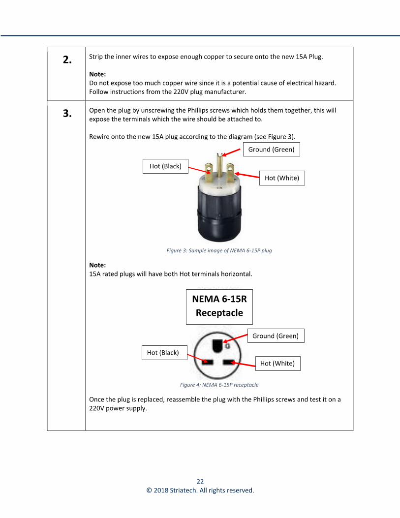
3. Open the plug by unscrewing the Phillips screws which holds them together, this will expose the terminals which the wire should be attached to. Rewire onto the new 15A plug according to the diagram (see Figure 3).
Figure 3: Sample image of NEMA 6-15P plug
Note: 15A rated plugs will have both Hot terminals horizontal.
Figure 4: NEMA 6-15P receptacle
Once the plug is replaced, reassemble the plug with the Phillips screws and test it on a 220V power supply.
Hot (Black)
Hot (White)
Ground (Green)
Hot (Black)
Hot (White)
Ground (Green)
NEMA 6-15R
Receptacle

23 © 2018 Striatech. All rights reserved.
Technical Support for Motor, Controller and Firmware Updates Contact:
Striatech 4499 126th Ave.
St. Petersburg, FL 33714, USA Ph: 727-202-9932 Fax: 727-623-0902
www.striatech.com www.rikontools.com