Embed Size (px)
DESCRIPTION
sm
Citation preview
SYKES GROUP PTY LTD
CP200 PUMPSET FOR
REF: W/O

Installation, Operation and Maintenance Manual.
Sykes Group Pty. Ltd.
Installation, Operation and Maintenance Manual.
Sykes Group Pty. Ltd.
SYKES GROUP PTY LTD
PUMP SPECIFICATION
PUMP TYPE: QSCP200
PUMP SIZE: 200mm x 200mm
ACTUAL IMPELLER DIAMETER: Ø295mm
ENGINE / MOTOR TYPE:
MAXIMUM PUMP RPM: 2000 rpm
PUMP NUMBER:
JOB NUMBER:
PLANT NUMBER: N/A
ENGINE / MOTOR NUMBER:

Installation, Operation and Maintenance Manual.
Sykes Group Pty. Ltd.
Installation, Operation and Maintenance Manual.
Sykes Group Pty. Ltd.
Installation, Operation and Maintenance Manual.
Sykes Group Pty. Ltd.
Installation, Operation and Maintenance Manual.
Sykes Group Pty. Ltd.
TECHNICAL DATA SHEET No. 1
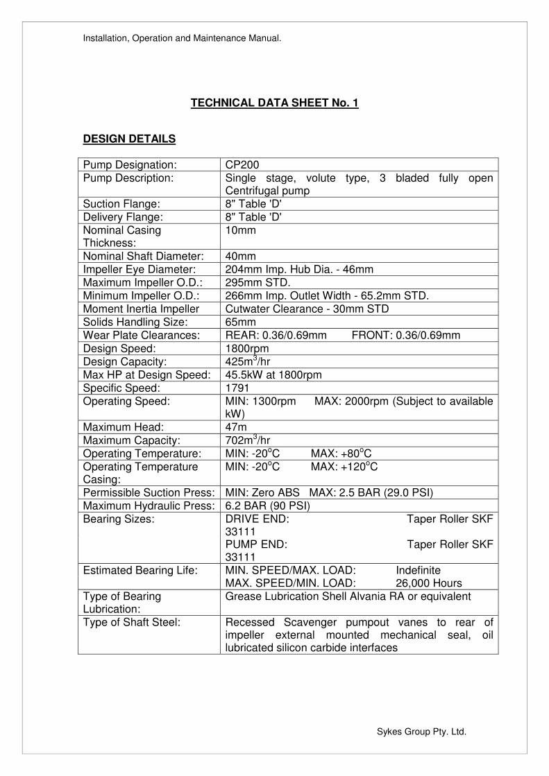
DESIGN DETAILS Pump Designation: CP200 Pump Description: Single stage, volute type, 3 bladed fully open
Centrifugal pump Suction Flange: 8" Table 'D' Delivery Flange: 8" Table 'D' Nominal Casing Thickness:
10mm
Nominal Shaft Diameter: 40mm Impeller Eye Diameter: 204mm Imp. Hub Dia. - 46mm Maximum Impeller O.D.: 295mm STD. Minimum Impeller O.D.: 266mm Imp. Outlet Width - 65.2mm STD. Moment Inertia Impeller Cutwater Clearance - 30mm STD Solids Handling Size: 65mm Wear Plate Clearances: REAR: 0.36/0.69mm FRONT: 0.36/0.69mm Design Speed: 1800rpm Design Capacity: 425m3/hr Max HP at Design Speed: 45.5kW at 1800rpm Specific Speed: 1791 Operating Speed: MIN: 1300rpm MAX: 2000rpm (Subject to available
kW) Maximum Head: 47m Maximum Capacity: 702m3/hr Operating Temperature: MIN: -20oC MAX: +80oC Operating Temperature Casing:
MIN: -20oC MAX: +120oC
Permissible Suction Press: MIN: Zero ABS MAX: 2.5 BAR (29.0 PSI) Maximum Hydraulic Press: 6.2 BAR (90 PSI) Bearing Sizes: DRIVE END: Taper Roller SKF
33111 PUMP END: Taper Roller SKF
33111 Estimated Bearing Life: MIN. SPEED/MAX. LOAD: Indefinite MAX. SPEED/MIN. LOAD: 26,000 Hours Type of Bearing Lubrication:
Grease Lubrication Shell Alvania RA or equivalent
Type of Shaft Steel: Recessed Scavenger pumpout vanes to rear of impeller external mounted mechanical seal, oil lubricated silicon carbide interfaces
Installation, Operation and Maintenance Manual.
Sykes Group Pty. Ltd.
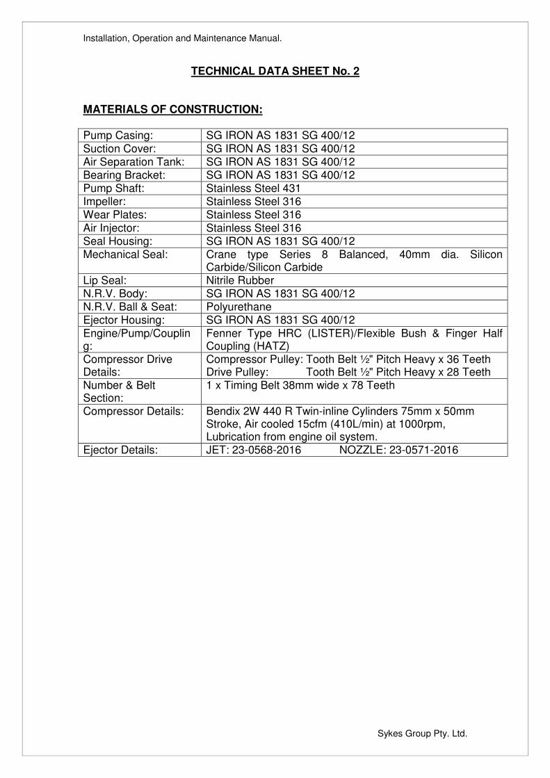
TECHNICAL DATA SHEET No. 2
MATERIALS OF CONSTRUCTION: Pump Casing: SG IRON AS 1831 SG 400/12 Suction Cover: SG IRON AS 1831 SG 400/12 Air Separation Tank: SG IRON AS 1831 SG 400/12 Bearing Bracket: SG IRON AS 1831 SG 400/12 Pump Shaft: Stainless Steel 431 Impeller: Stainless Steel 316 Wear Plates: Stainless Steel 316 Air Injector: Stainless Steel 316 Seal Housing: SG IRON AS 1831 SG 400/12 Mechanical Seal: Crane type Series 8 Balanced, 40mm dia. Silicon
Carbide/Silicon Carbide Lip Seal: Nitrile Rubber N.R.V. Body: SG IRON AS 1831 SG 400/12 N.R.V. Ball & Seat: Polyurethane Ejector Housing: SG IRON AS 1831 SG 400/12 Engine/Pump/Coupling:
Fenner Type HRC (LISTER)/Flexible Bush & Finger Half Coupling (HATZ)
Compressor Drive Details:
Compressor Pulley: Tooth Belt ½" Pitch Heavy x 36 Teeth Drive Pulley: Tooth Belt ½" Pitch Heavy x 28 Teeth
Number & Belt Section:
1 x Timing Belt 38mm wide x 78 Teeth
Compressor Details: Bendix 2W 440 R Twin-inline Cylinders 75mm x 50mm Stroke, Air cooled 15cfm (410L/min) at 1000rpm, Lubrication from engine oil system.
Ejector Details: JET: 23-0568-2016 NOZZLE: 23-0571-2016
Installation, Operation and Maintenance Manual.
Sykes Group Pty. Ltd.
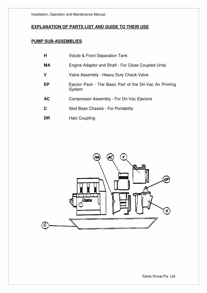
EXPLANATION OF PARTS LIST AND GUIDE TO THEIR USE PUMP SUB-ASSEMBLIES H Volute & Front Separation Tank
MA Engine Adaptor and Shaft - For Close Coupled Units
V Valve Assembly - Heavy Duty Check Valve EP Ejector Pack - The Basic Part of the Dri-Vac Air Priming
System
AC Compressor Assembly - For Dri-Vac Ejectors
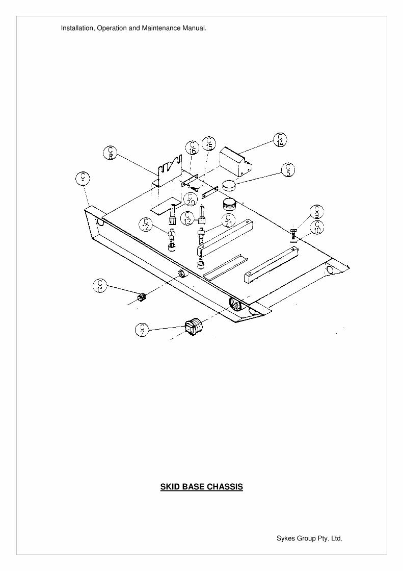
C Skid Base Chassis - For Portability
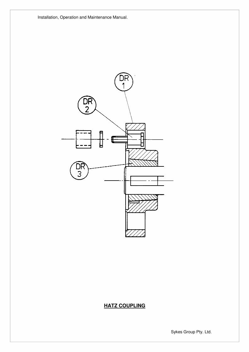
DR Hatz Coupling

Installation, Operation and Maintenance Manual.
Sykes Group Pty. Ltd.
Installation, Operation and Maintenance Manual.
Sykes Group Pty. Ltd.
OPERATING AND MAINTENANCE INSTRUCTIONS
Operation Before attempting to start the unit familiarise yourself with the engine controls as mentioned in the Manufacturer's Handbook and also the starting procedure. It is advisable to turn the unit over slowly before starting to ensure that all components are free and easy to turn. Once started, the compressor will automatically come in at the correct speed to prime the pump unit. When the engine has started, the pump requires no adjustment as the engine speeds are set at WORKS. REPAIRS Seal Replacement Drain water from pump and non-return valve. Drain oil from mechanical seal cavity. Remove the front cover, impeller and rear wearplate allowing direct access to the mechanical seal. Remove mechanical seal and sleeve assembly, check oil seal (MA31) has not been damaged or the adjacent sleeve scored. Renew where necessary ensuring that oil seal is replaced squarely in it's housing. To renew the mechanical seal, remove shaft sleeve (H20) complete with seal unit (H8). If seal unit is in good condition it may only be necessary to remove carbide rotating face from seal unit. Before fitting a complete new seal assembly ensure that all sharp edges are removed and all working faces are clean and free from any foreign matter. To fit a new seal, smear the shaft and inside surfaces of seal bellows with a light oil or swarfega. Do not use a heavy grease, silicon or P.T.F.E. based lubricant. Ensure that the seal unit is pressed squarely and evenly over the shaft and hard back against the seal shoulder (H20). Fit O-ring (H21) to inside diameter of sleeve and ensure there are no sharp edges where the O-ring passes over. Before fitting the seal rotating face into the drive grooves use a small amount of grease on the rear face to secure face in position whilst assembly is taking place. Fit rear wearplate carrying the seal static face using a non-adhesive sealant on rear face of wearplate. Seal tension is automatically obtained when the wearplate and impeller are re-fitted. Ensure rear impeller clearance is between 0.3mm and 0.6mm. Fill oil chamber with SAE20/20 grade of oil and check assembly rotates freely. Rebuild pump casing assembly onto adaptor. Compressor Belt Replacement Remove pulley guard draw pump assembly away from engine flywheel housing. Remove old belt and taper lock bush from pump pulley (AC9). Ease replacement belt (AC11) over pulleys, realign pulleys and refit taper lock bush. Check belt tension then refit pump unit onto engine. The compressor tooth belt drive has fixed centers so no adjustment is necessary. The normal operating air pressure is 3.44 - 5.17 bar (50-75psi).
Installation, Operation and Maintenance Manual.
Sykes Group Pty. Ltd.
OPERATING AND MAINTENANCE INSTRUCTIONS Engine Adaptor Assembly Remove pump assembly from adaptor. Remove drive coupling and pump pulley (AC9) from pump shaft. It may also be convenient for working, to remove compressor (AC1). Remove rear bearing cover (MA18) and press shaft (MA2) out of adaptor (MA1), dismantle bearings (MA11). Inspect and clean all items and renew when necessary. Reassemble adaptor and pump in reverse order.
Installation, Operation and Maintenance Manual.
Sykes Group Pty. Ltd.
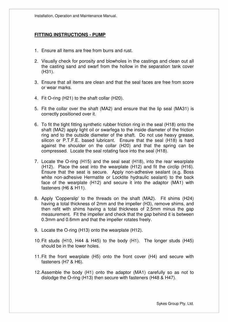
FITTING INSTRUCTIONS - PUMP 1. Ensure all items are free from burrs and rust. 2. Visually check for porosity and blowholes in the castings and clean out all
the casting sand and swarf from the hollow in the separation tank cover (H31).
3. Ensure that all items are clean and that the seal faces are free from score
or wear marks. 4. Fit O-ring (H21) to the shaft collar (H20). 5. Fit the collar over the shaft (MA2) and ensure that the lip seal (MA31) is
correctly positioned over it. 6. To fit the tight fitting synthetic rubber friction ring in the seal (H18) onto the
shaft (MA2) apply light oil or swarfega to the inside diameter of the friction ring and to the outside diameter of the shaft. Do not use heavy grease, silicon or P.T.F.E. based lubricant. Ensure that the seal (H18) is hard against the shoulder on the collar (H20) and that the spring can be compressed. Locate the seal rotating face into the seal (H18).
7. Locate the O-ring (H15) and the seal seat (H18), into the rear wearplate
(H12). Place the seat into the wearplate (H12) and fit the circlip (H16). Ensure that the seat is secure. Apply non-adhesive sealant (e.g. Boss white non-adhesive Hermatite or Locktite hydraulic sealant) to the back face of the wearplate (H12) and secure it into the adaptor (MA1) with fasteners (H6 & H11).
8. Apply 'Copperslip' to the threads on the shaft (MA2). Fit shims (H24)
having a total thickness of 2mm and the impeller (H3), remove shims, and then refit with shims having a total thickness of 2.5mm minus the gap measurement. Fit the impeller and check that the gap behind it is between 0.3mm and 0.6mm and that the impeller rotates freely.
9. Locate the O-ring (H13) onto the wearplate (H12). 10. Fit studs (H10, H44 & H45) to the body (H1). The longer studs (H45)
should be in the lower holes. 11. Fit the front wearplate (H5) onto the front cover (H4) and secure with
fasteners (H7 & H6). 12. Assemble the body (H1) onto the adaptor (MA1) carefully so as not to
dislodge the O-ring (H13) then secure with fasteners (H48 & H47).
Installation, Operation and Maintenance Manual.
Sykes Group Pty. Ltd.
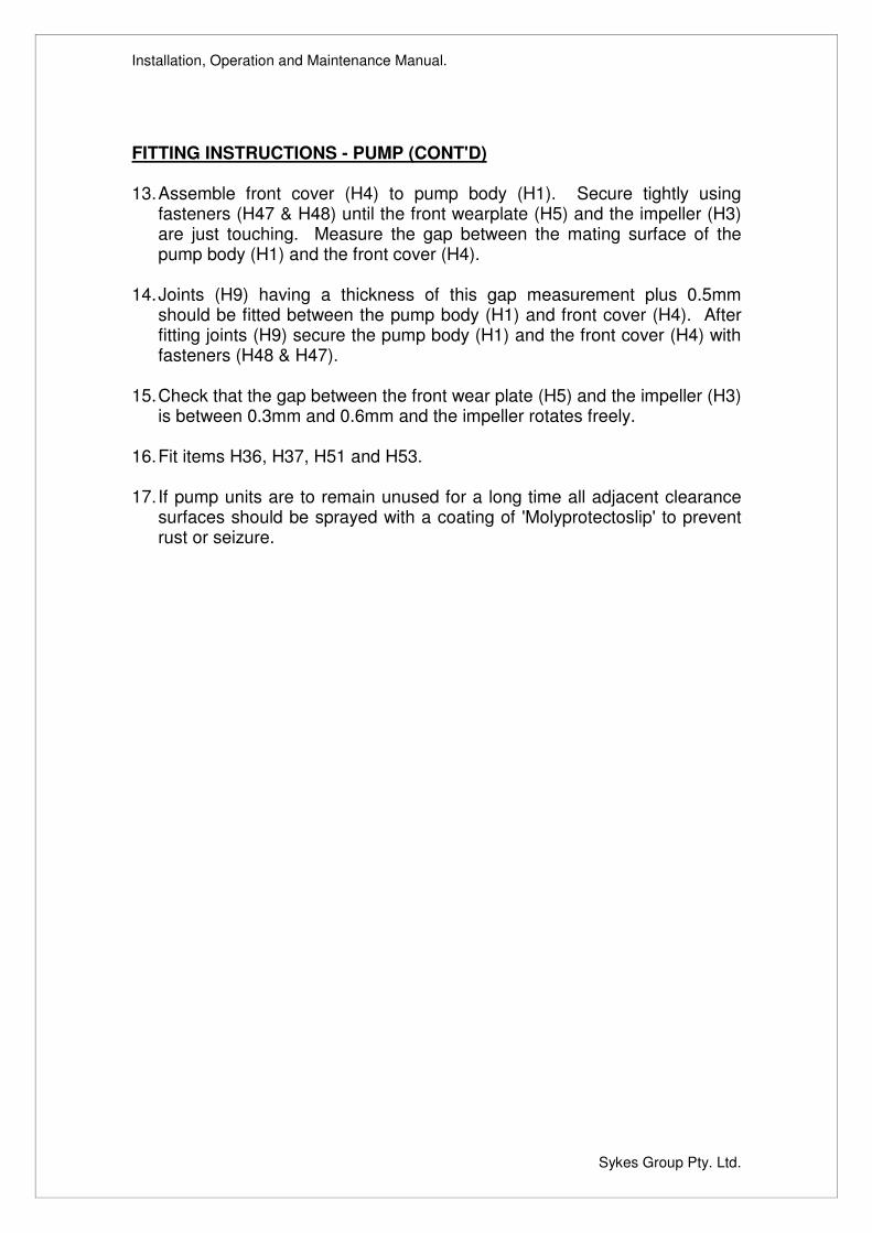
FITTING INSTRUCTIONS - PUMP (CONT'D) 13. Assemble front cover (H4) to pump body (H1). Secure tightly using
fasteners (H47 & H48) until the front wearplate (H5) and the impeller (H3) are just touching. Measure the gap between the mating surface of the pump body (H1) and the front cover (H4).
14. Joints (H9) having a thickness of this gap measurement plus 0.5mm
should be fitted between the pump body (H1) and front cover (H4). After fitting joints (H9) secure the pump body (H1) and the front cover (H4) with fasteners (H48 & H47).
15. Check that the gap between the front wear plate (H5) and the impeller (H3)
is between 0.3mm and 0.6mm and the impeller rotates freely. 16. Fit items H36, H37, H51 and H53. 17. If pump units are to remain unused for a long time all adjacent clearance
surfaces should be sprayed with a coating of 'Molyprotectoslip' to prevent rust or seizure.
Installation, Operation and Maintenance Manual.
Sykes Group Pty. Ltd.
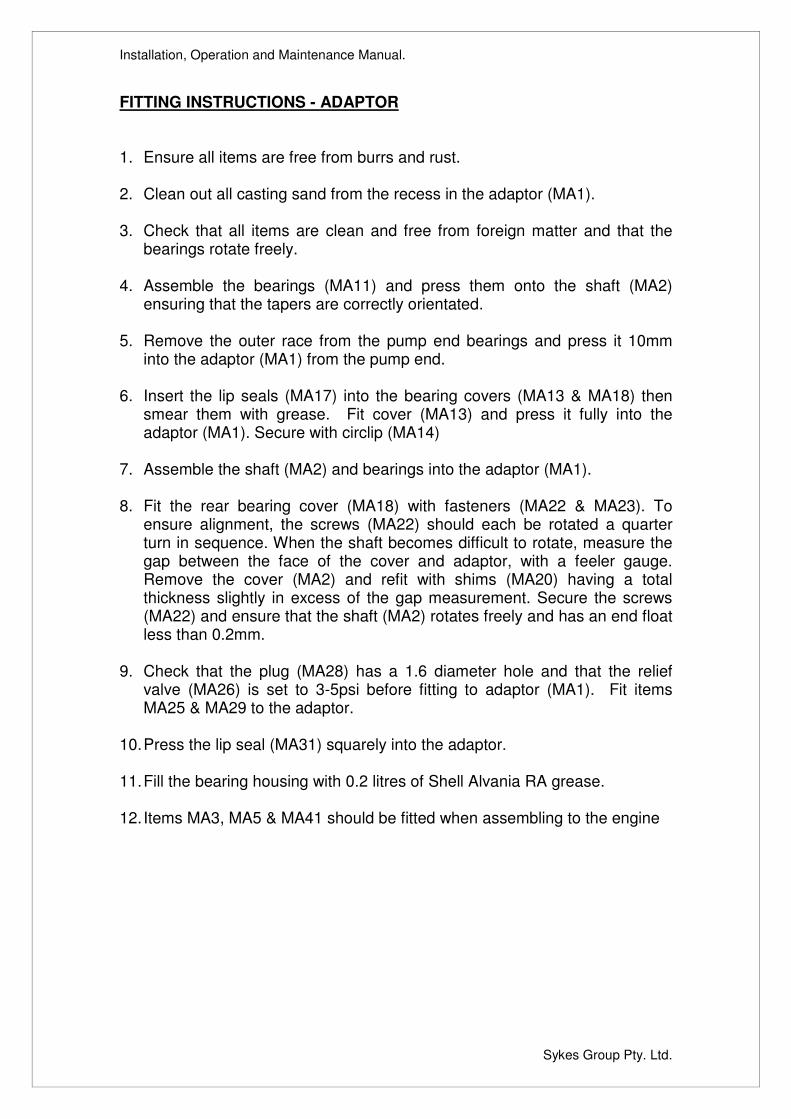
FITTING INSTRUCTIONS - ADAPTOR 1. Ensure all items are free from burrs and rust. 2. Clean out all casting sand from the recess in the adaptor (MA1). 3. Check that all items are clean and free from foreign matter and that the
bearings rotate freely. 4. Assemble the bearings (MA11) and press them onto the shaft (MA2)
ensuring that the tapers are correctly orientated. 5. Remove the outer race from the pump end bearings and press it 10mm
into the adaptor (MA1) from the pump end. 6. Insert the lip seals (MA17) into the bearing covers (MA13 & MA18) then
smear them with grease. Fit cover (MA13) and press it fully into the adaptor (MA1). Secure with circlip (MA14)
7. Assemble the shaft (MA2) and bearings into the adaptor (MA1). 8. Fit the rear bearing cover (MA18) with fasteners (MA22 & MA23). To
ensure alignment, the screws (MA22) should each be rotated a quarter turn in sequence. When the shaft becomes difficult to rotate, measure the gap between the face of the cover and adaptor, with a feeler gauge. Remove the cover (MA2) and refit with shims (MA20) having a total thickness slightly in excess of the gap measurement. Secure the screws (MA22) and ensure that the shaft (MA2) rotates freely and has an end float less than 0.2mm.
9. Check that the plug (MA28) has a 1.6 diameter hole and that the relief
valve (MA26) is set to 3-5psi before fitting to adaptor (MA1). Fit items MA25 & MA29 to the adaptor.
10. Press the lip seal (MA31) squarely into the adaptor. 11. Fill the bearing housing with 0.2 litres of Shell Alvania RA grease. 12. Items MA3, MA5 & MA41 should be fitted when assembling to the engine
Installation, Operation and Maintenance Manual.
Sykes Group Pty. Ltd.
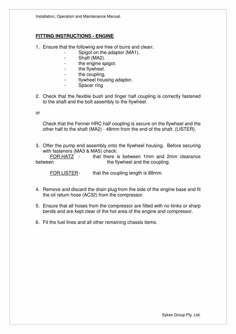
FITTING INSTRUCTIONS - ENGINE 1. Ensure that the following are free of burrs and clean:
- Spigot on the adaptor (MA1). - Shaft (MA2). - the engine spigot. - the flywheel. - the coupling. - flywheel housing adaptor. - Spacer ring
2. Check that the flexible bush and finger half coupling is correctly fastened
to the shaft and the bolt assembly to the flywheel. or
Check that the Fenner HRC half coupling is secure on the flywheel and the other half to the shaft (MA2) - 48mm from the end of the shaft. (LISTER).
3. Offer the pump end assembly onto the flywheel housing. Before securing
with fasteners (MA3 & MA5) check: FOR HATZ - that there is between 1mm and 2mm clearance
between the flywheel and the coupling.
FOR LISTER - that the coupling length is 88mm.
4. Remove and discard the drain plug from the side of the engine base and fit
the oil return hose (AC32) from the compressor. 5. Ensure that all hoses from the compressor are fitted with no kinks or sharp
bends and are kept clear of the hot area of the engine and compressor. 6. Fit the fuel lines and all other remaining chassis items.
Installation, Operation and Maintenance Manual.
Sykes Group Pty. Ltd.
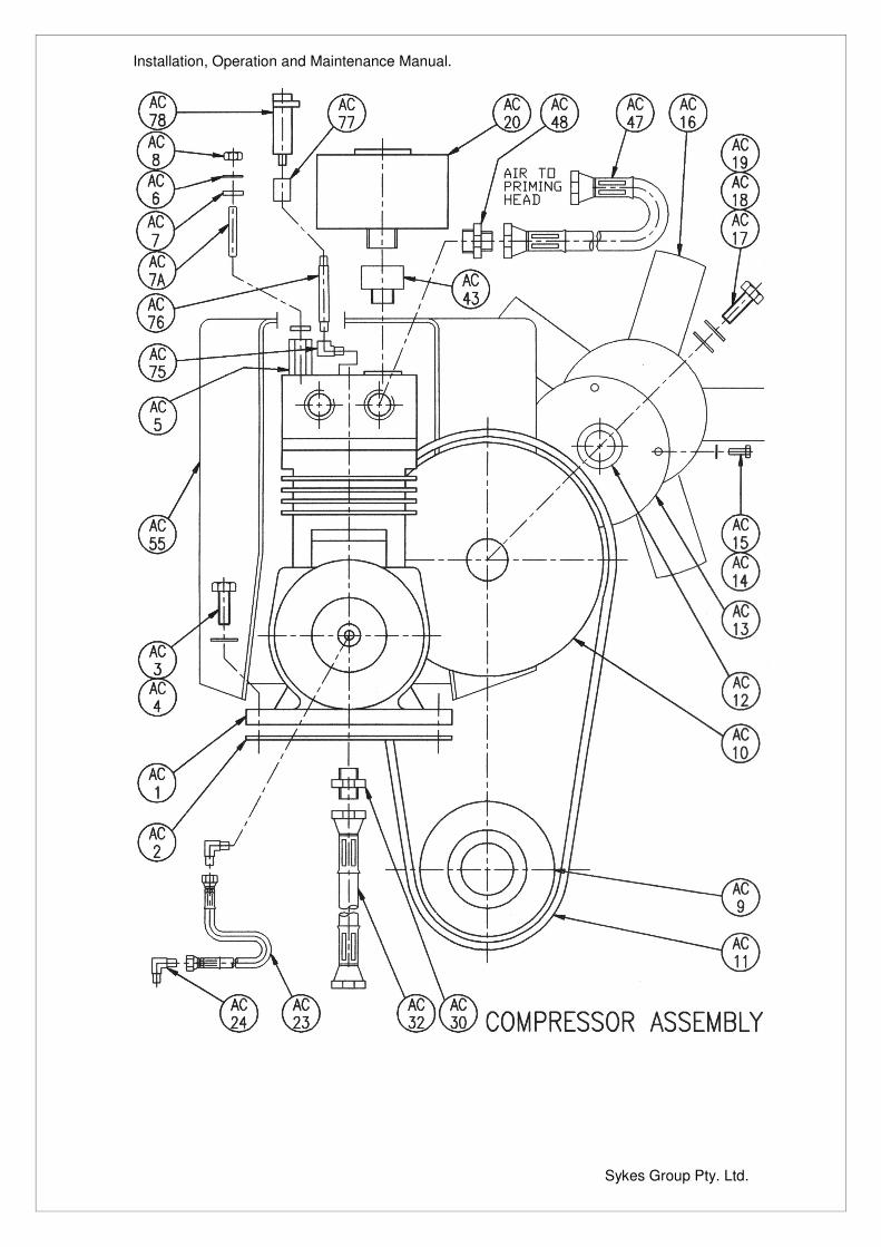
FITTING INSTRUCTIONS - COMPRESSOR ASSEMBLY 1. Ensure all items are clean and that the hoses are free from foreign matter. 2. Do not use excessive jointing compound (eg. Stag, Neolite, Non-Adhesive
Hermatite etc) when fitting these items and ensure that it does not enter the bores. This may cause a blockage in the oil or air lines.
3. Fit gasket (AC2) to the compressor (AC1) position on adaptor (MA1) and
secure with fasteners (AC4 & AC3). 4. Secure the compressor pulley (AC10) to the compressor (AC1) with the
nut and split pin. Remove the taperlock bush from the pump pulley (AC9) then pass the pulley over the shaft (MA2). Ease the belt (AC11) over the pulleys, and fit the key (MA41). Align the pulleys then refit the taperlock bush to the pump pulley (AC9) and secure it to the shaft (MA2).
5. Remove and discard four cylinder head screws from the compressor and
ensure the compressed air port is located at the opposite end to fan. 6. Connect the compressed air hose (AC47) between the compressor (AC1)
and the jet sleeve (EP8). 7. Fit the oil pipe fittings (AC23, AC30 & AC32) to the compressor (AC1). 8. Connect air intake fittings (AC43 & AC20). 9. Ensure that the belt and pulleys are free to rotate.
Installation, Operation and Maintenance Manual.
Sykes Group Pty. Ltd.
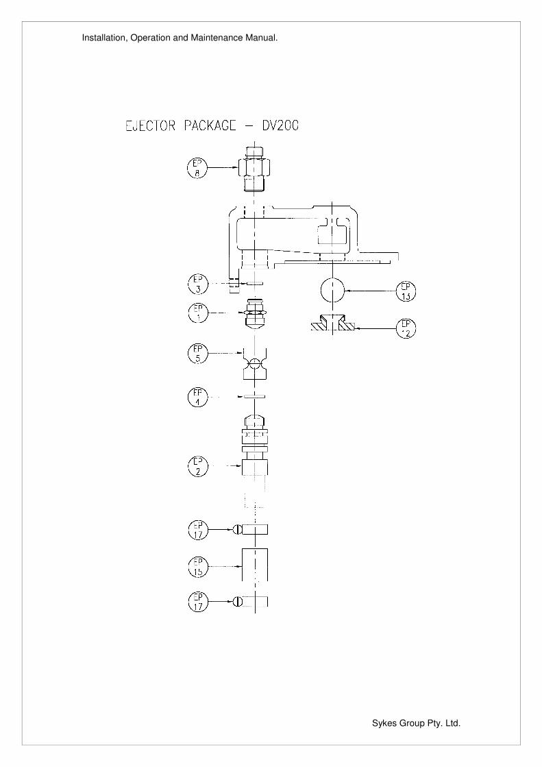
FITTING INSTRUCTIONS - EJECTOR PACKAGE 1. Check that all items are clean and free from burrs. The jet and nozzle
should only be cleaned with paraffin or similar cleaner. Wire should not be used as this will enlarge the bores.
2. Do not use excessive jointing compound when fitting these items and
ensure that it does not enter the bores. This may cause a blockage in the ejector.
3. Fit, in their grooves, o-ring (EP3) onto jet (EP1) and o-ring (EP4) onto
nozzle (EP2) . 4. Screw by hand, the jet (EP1) and the nozzle (EP2) to the collar (EP5). 5. Release the location screw (H36) and insert the assembly into the
separation tank cover (H31), then re-tighten the screw (H36) so that it locates in the groove on the nozzle (EP2).
6. Screw the jet sleeve (EP8) by hand into the separation tank cover (H31).
A spanner should only be used for the final quarter turn. 7. Place the ball (EP13) in the separation tank cover (H31), then secure ball
seat (EP12). 8. Fit the separation tank cover (H31) to the pump body (H1) with gasket
filters (H33) and fasteners (H29 & H30). 9. Push the exhaust hose (EP15) onto the nozzle (EP2). Fasten using clamp
(EP17). 10. Push air muffler (EP16) into the exhaust hose (EP15). Fasten using clamp
(EP17).
Installation, Operation and Maintenance Manual.
Sykes Group Pty. Ltd.
DV200 TESTING INSPECTION 1. Drain the water from the pump and the non-return valve (Ref items H27). 2. Remove the non-return valve and inspect the flap and seat for wear. 3. Drain the oil from the engine and the pump (Ref item MA29). 4. Dismantle the pump end completely (Ref items H31, H1, H3, H12, H4 and
H5). 5. If the oil seal (MA31) has scored the collar (H20), it may be pushed in
2mm to seal on an unscored area of the sleeve. Ensure that the oil seal is positioned squarely and that it is less than 8mm from the machined face of the adaptor (MA1).
6. Worn seal faces may be reclaimed by lapping faces to a surface finish of 3
sodium light bands. Note that the stationary seat was originally lapped both sides and may be reversed in the wearplate (H12).
7. Check that the shaft rotates freely and has an end float less than 0.2mm. 8. Clean and inspect all components and renew where necessary. Do not
use abrasive materials or solutions to clean the ejector assembly. Renew all nitrile seals.
9. Reassemble the complete pump end and non-return valve (Ref Fitting
Instructions). 10. Drain the fuel tank. 11. Detach fuel, oil and air hoses. Clean and ensure that they are not blocked.
Test the relief valves (MA26 at 3 to 5 psi, and AC78 at 90 to 100 psi). 12. Check pulley alignment and belt condition (Ref items AC9, AC10 & AC11).
Check the security of pulleys and flexible couplings. 13. Reassemble the complete unit. TESTING 1. Fill the seal housing (Ref item MA28) with half a litre of SAE20/20 oil and
the bearing housing (Ref item MA25) with Shell Alvania RA grease. 2. Fill engine with 5.3 litres of SAE 20/20 detergent oil for testing.
Installation, Operation and Maintenance Manual.
Sykes Group Pty. Ltd.
VACUUM TEST 1. The assembled pump should be subjected to a vacuum to show up any air
leaks. Disconnect the compressor hose, fit a compressor air line to the jet, and hold a vacuum gauge assembly against the pump suction flange. The pump end should seal against a minimum vacuum of 0.81 bar (24 inches mercury). With closed valves the vacuum does not hold, air may be leaking at the mechanical seal, non-return valves, pump joints or porous castings.
2. When the tests are successful, refit the compressor hose. DYNAMIC TEST 1. Before starting the engine, check that the shaft, pulleys and belt are free to
rotate with the guards in position. 2. Rotate engine by hand for a minimum of six complete revolutions, listen for
injector 'creak' - indication the injector pump is working. 3. Start pump and run completely dry for a minimum period of 10 minutes
(initial run up speed at 1500rpm increasing during test to 1700rpm). During this period generally check and observe for any unusual vibrations, overheating, fuel, oil or air leaks.
4. These faults must be rectified immediately to prevent a possible engine
seizure.
5. After the dry running period check that the pump unit will raise a minimum vacuum of 0.81 bar (24 inches mercury).
(Consult engine manufacturers handbook for oil, fuel, speed control and stop details).

Installation, Operation and Maintenance Manual.
Sykes Group Pty. Ltd.
EJECTOR TEST 1. If the ejector was unsuccessful in the dynamic test, it may be tested,
remove the pump, as shown below. 2. Check the performance of the ejector.
Minimum allowable vacuum 0.81bar (24" Hg or 27.24 ft water) at an air pressure of 2.75 - 4.14 bars (40-60 psi).
3. When the test is successful, refit the ejector assembly to the pump.
EJECTOR TEST

Installation, Operation and Maintenance Manual.
Sykes Group Pty. Ltd.
PUMP PROBLEMS - Systems & Likely Causes 1. Pump does not prime Suction lift too great.
Insufficient water at suction inlet. Suction inlet or strainer blocked. Suction line not air tight. Suction hose collapsed. Non return valve ball not seating Mechanical seal drawing air into pump Ejector jet or nozzle blocked or badly worn. Ejector non-return valve ball stuck. Separation tank cover blocked. Compressor pipe leaking air. Compressor no delivering sufficient air Compressor belt drive faulty.
2. Not enough liquid Incorrect engine speed. Discharge head too high. Suction lift too great. Suction inlet or strainer blocked. Suction line not air tight. Suction hose collapsed. Mechanical seal drawing air into pump. Obstruction in pump casing/impeller. Impeller excessively worn. Delivery hose punctured or blocked
3. Pump ceases to deliver liquid after a time.
Suction lift too great. Insufficient water at suction inlet. Suction inlet or strainer blocked. Suction hose collapsed. Excessive air leak in suction line. Mechanical seal drawing air into pump. Obstruction in pump casing/impeller. Delivery hose punctured or blocked.
4. Pump takes excessive power Engine speed too high. Obstruction between impeller and casing. Viscosity and SG of liquid being pumped too high
5. Pump vibrating or overheating Engine speed too high. Obstruction in pump casing/impeller. Impeller damaged. Cavitation due to excessive suction lift.
6. Pump leaking at seal housing Mechanical seal damaged or worn.
Installation, Operation and Maintenance Manual.
Sykes Group Pty. Ltd.
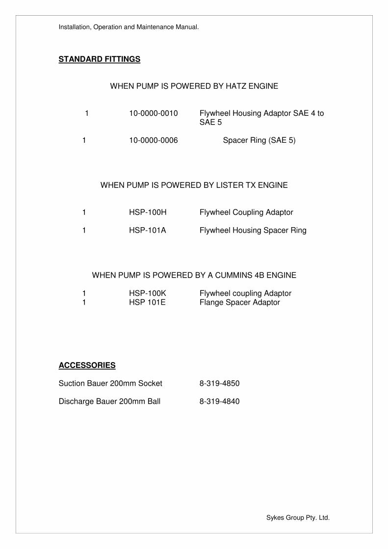
STANDARD FITTINGS
WHEN PUMP IS POWERED BY HATZ ENGINE 1 10-0000-0010 Flywheel Housing Adaptor SAE 4 to
SAE 5 1 10-0000-0006 Spacer Ring (SAE 5)
WHEN PUMP IS POWERED BY LISTER TX ENGINE 1 HSP-100H Flywheel Coupling Adaptor 1 HSP-101A Flywheel Housing Spacer Ring
WHEN PUMP IS POWERED BY A CUMMINS 4B ENGINE 1 HSP-100K Flywheel coupling Adaptor 1 HSP 101E Flange Spacer Adaptor ACCESSORIES Suction Bauer 200mm Socket 8-319-4850 Discharge Bauer 200mm Ball 8-319-4840

Installation, Operation and Maintenance Manual.
Sykes Group Pty. Ltd.
Installation, Operation and Maintenance Manual.
Sykes Group Pty. Ltd.
AIR COMPRESSOR
Installation, Operation and Maintenance Manual.
Sykes Group Pty. Ltd.
Installation, Operation and Maintenance Manual.
Sykes Group Pty. Ltd.
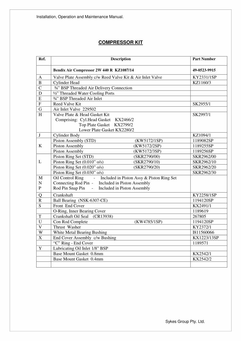
COMPRESSOR KIT
Ref. Description Part Number
Bendix Air Compressor 2W 440 R KZ1087/14 49-0523-9915 A Valve Plate Assembly c/w Reed Valve Kit & Air Inlet Valve KY2331/1SP B Cylinder Head KZ1160/3 C ¾” BSP Threaded Air Delivery Connection D ½” Threaded Water Cooling Ports E ¾” BSP Threaded Air Inlet F Reed Valve Kit SK2955/1 G Air Inlet Valve 229502 H
Valve Plate & Head Gasket Kit Comprising: Cyl.Head Gasket KX2466/2 Top Plate Gasket KX2799/2 Lower Plate Gasket KX2280/2
SK2997/1
J Cylinder Body KZ1094/1 Piston Assembly (STD) (KW5172/1SP) 1189082SP Piston Assembly (KW5172/2SP) 1189255SP
K
Piston Assembly (KW5172/3SP) 1189256SP Piston Ring Set (STD) (SKR2790/00) SKR2962/00 Piston Ring Set (0.010” o/s) (SKR2790/10) SKR2962/10 Piston Ring Set (0.020” o/s) (SKR2790/20) SKR2962/20
L
Piston Ring Set (0.030” o/s) SKR2962/30 M N P
Oil Control Ring - Included in Piston Assy & Piston Ring Set Connecting Rod Pin - Included in Piston Assembly Rod Pin Snap Pin - Included in Piston Assembly
Q Crankshaft KY2258/1SP R Ball Bearing (NSK-6307-CE) 1194120SP S Front End Cover KX2491/1 O-Ring, Inner Bearing Cover 1189619 T Crankshaft Oil Seal (CR13938) 267805 U Con Rod Complete (KW4785/1SP) 1194120SP V Thrust Washer KY2372/1 W White Metal Bearing Bushing I811560066 X End Cover Assembly c/w Bushing KX1223/13SP “C” Ring - End Cover 1189571 Y Lubricating Oil Inlet 1/8” BSP Base Mount Gasket 0.8mm KX2542/1 Base Mount Gasket 0.4mm KX2542/2

Installation, Operation and Maintenance Manual.
Sykes Group Pty. Ltd.
Installation, Operation and Maintenance Manual.
Sykes Group Pty. Ltd.
PARTS LISTS
Installation, Operation and Maintenance Manual.
Sykes Group Pty. Ltd.
Installation, Operation and Maintenance Manual.
Sykes Group Pty. Ltd.
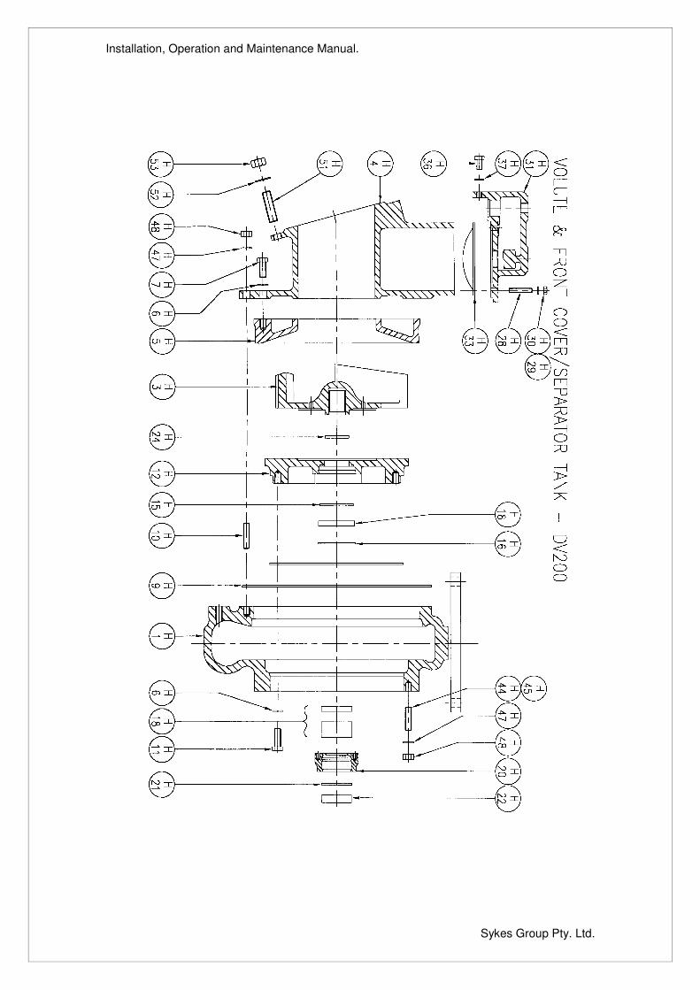
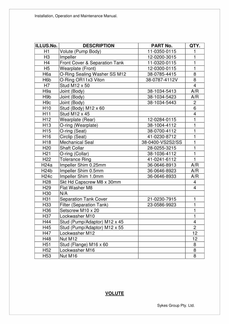
ILLUS.No. DESCRIPTION PART No. QTY.
H1 Volute (Pump Body) 11-0350-0115 1 H3 Impeller 12-0200-3015 1 H4 Front Cover & Separation Tank 11-0320-0115 1 H5 Wearplate (Front) 12-0300-0115 1
H6a O-Ring Sealing Washer SS M12 38-0785-4415 8 H6b O-Ring OR11x3 Viton 38-0787-4112V 8 H7 Stud M12 x 50 4
H9a Joint (Body) 38-1034-5413 A/R H9b Joint (Body) 38-1034-5423 A/R H9c Joint (Body) 38-1034-5443 2 H10 Stud (Body) M12 x 60 6 H11 Stud M12 x 45 4 H12 Wearplate (Rear) 12-0284-0115 1 H13 O-ring (Wearplate) 38-1004-4112 1 H15 O-ring (Seat) 38-0700-4112 1 H16 Circlip (Seat) 41-0230-8712 1 H18 Mechanical Seal 38-0400-VS2S2/SS 1 H20 Shaft Collar 28-0255-3215 1 H21 O-ring (Collar) 38-1036-4112 1 H22 Tolerance Ring 41-0241-6112 1
H24a Impeller Shim 0.25mm 36-0646-8913 A/R H24b Impeller Shim 0.5mm 36-0646-8923 A/R H24c Impeller Shim 1.0mm 36-0646-8933 A/R H28 Skt Hd Capscrew M8 x 30mm 4 H29 Flat Washer M8 4 H30 N/A H31 Separation Tank Cover 21-0230-7915 1 H33 Filter (Separation Tank) 23-0586-9923 1 H36 Setscrew M10 x 20 1 H37 Lockwasher M10 1 H44 Stud (Pump/Adaptor) M12 x 45 4 H45 Stud (Pump/Adaptor) M12 x 55 2 H47 Lockwasher M12 12 H48 Nut M12 12 H51 Stud (Flange) M16 x 60 8 H52 Lockwasher M16 8 H53 Nut M16 8
VOLUTE

Installation, Operation and Maintenance Manual.
Sykes Group Pty. Ltd.

Installation, Operation and Maintenance Manual.
Sykes Group Pty. Ltd.
Installation, Operation and Maintenance Manual.
Sykes Group Pty. Ltd.
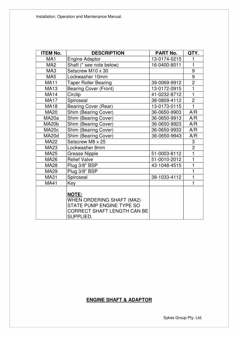
ITEM No. DESCRIPTION PART No. QTY. MA1 Engine Adaptor 13-0174-0215 1 MA2 Shaft (* see note below) 16-0400-8011 1 MA3 Setscrew M10 x 30 9 MA5 Lockwasher 10mm 9
MA11 Taper Roller Bearing 39-0069-9912 2 MA13 Bearing Cover (Front) 13-0172-0915 1 MA14 Circlip 41-0232-8712 1 MA17 Spiroseal 38-0809-4112 2 MA18 Bearing Cover (Rear) 13-0173-0115 1 MA20 Shim (Bearing Cover) 36-0650-9903 A/R
MA20a Shim (Bearing Cover) 36-0650-9913 A/R MA20b Shim (Bearing Cover) 36-0650-9923 A/R MA20c Shim (Bearing Cover) 36-0650-9933 A/R MA20d Shim (Bearing Cover) 36-0650-9943 A/R MA22 Setscrew M8 x 25 3 MA23 Lockwasher 8mm 3 MA25 Grease Nipple 51-0003-8112 1 MA26 Relief Valve 51-0010-2012 1 MA28 Plug 3/8" BSP 43-1048-4515 1 MA29 Plug 3/8" BSP 1 MA31 Spiroseal 38-1033-4112 1 MA41 Key 1
NOTE: WHEN ORDERING SHAFT (MA2) STATE PUMP ENGINE TYPE SO CORRECT SHAFT LENGTH CAN BE SUPPLIED.
ENGINE SHAFT & ADAPTOR
Installation, Operation and Maintenance Manual.
Sykes Group Pty. Ltd.
Installation, Operation and Maintenance Manual.
Sykes Group Pty. Ltd.
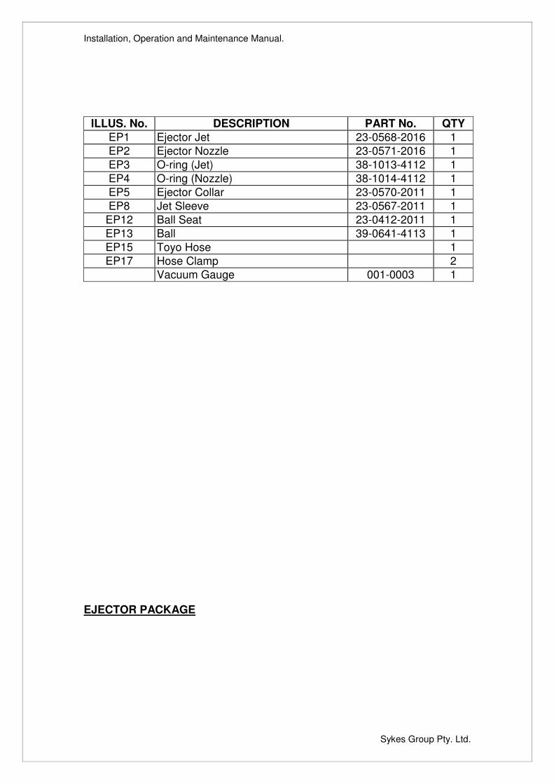
ILLUS. No. DESCRIPTION PART No. QTY EP1 Ejector Jet 23-0568-2016 1 EP2 Ejector Nozzle 23-0571-2016 1 EP3 O-ring (Jet) 38-1013-4112 1 EP4 O-ring (Nozzle) 38-1014-4112 1 EP5 Ejector Collar 23-0570-2011 1 EP8 Jet Sleeve 23-0567-2011 1
EP12 Ball Seat 23-0412-2011 1 EP13 Ball 39-0641-4113 1 EP15 Toyo Hose 1 EP17 Hose Clamp 2
Vacuum Gauge 001-0003 1 EJECTOR PACKAGE
Installation, Operation and Maintenance Manual.
Sykes Group Pty. Ltd.
Installation, Operation and Maintenance Manual.
Sykes Group Pty. Ltd.
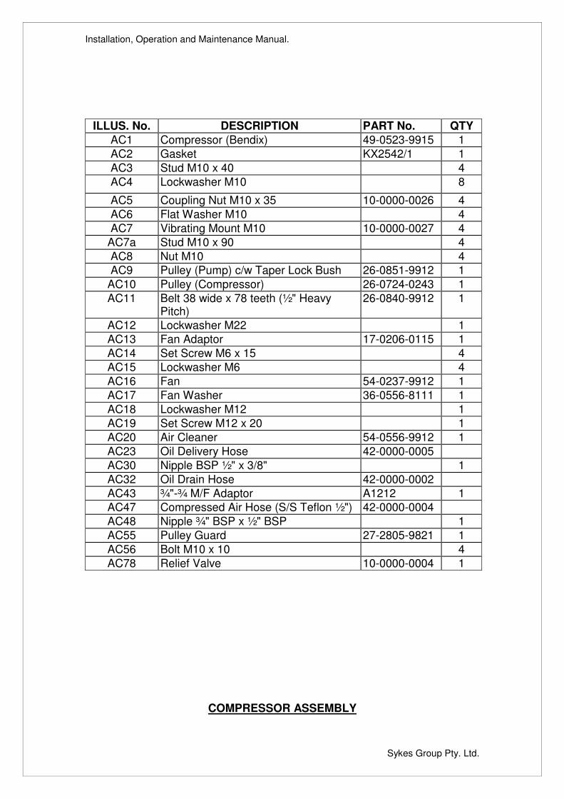
ILLUS. No. DESCRIPTION PART No. QTY AC1 Compressor (Bendix) 49-0523-9915 1 AC2 Gasket KX2542/1 1 AC3 Stud M10 x 40 4 AC4 Lockwasher M10 8
AC5 Coupling Nut M10 x 35 10-0000-0026 4 AC6 Flat Washer M10 4 AC7 Vibrating Mount M10 10-0000-0027 4
AC7a Stud M10 x 90 4 AC8 Nut M10 4 AC9 Pulley (Pump) c/w Taper Lock Bush 26-0851-9912 1
AC10 Pulley (Compressor) 26-0724-0243 1 AC11 Belt 38 wide x 78 teeth (½" Heavy
Pitch) 26-0840-9912 1
AC12 Lockwasher M22 1 AC13 Fan Adaptor 17-0206-0115 1 AC14 Set Screw M6 x 15 4 AC15 Lockwasher M6 4 AC16 Fan 54-0237-9912 1 AC17 Fan Washer 36-0556-8111 1 AC18 Lockwasher M12 1 AC19 Set Screw M12 x 20 1 AC20 Air Cleaner 54-0556-9912 1 AC23 Oil Delivery Hose 42-0000-0005 AC30 Nipple BSP ½" x 3/8" 1 AC32 Oil Drain Hose 42-0000-0002 AC43 ¾"-¾ M/F Adaptor A1212 1 AC47 Compressed Air Hose (S/S Teflon ½") 42-0000-0004 AC48 Nipple ¾" BSP x ½" BSP 1 AC55 Pulley Guard 27-2805-9821 1 AC56 Bolt M10 x 10 4 AC78 Relief Valve 10-0000-0004 1
COMPRESSOR ASSEMBLY
Installation, Operation and Maintenance Manual.
Sykes Group Pty. Ltd.
HATZ COUPLING
Installation, Operation and Maintenance Manual.
Sykes Group Pty. Ltd.
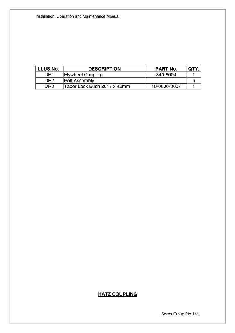
ILLUS.No. DESCRIPTION PART No. QTY. DR1 Flywheel Coupling 340-6004 1 DR2 Bolt Assembly 6 DR3 Taper Lock Bush 2017 x 42mm 10-0000-0007 1
HATZ COUPLING
Installation, Operation and Maintenance Manual.
Sykes Group Pty. Ltd.
SKID BASE CHASSIS
Installation, Operation and Maintenance Manual.
Sykes Group Pty. Ltd.
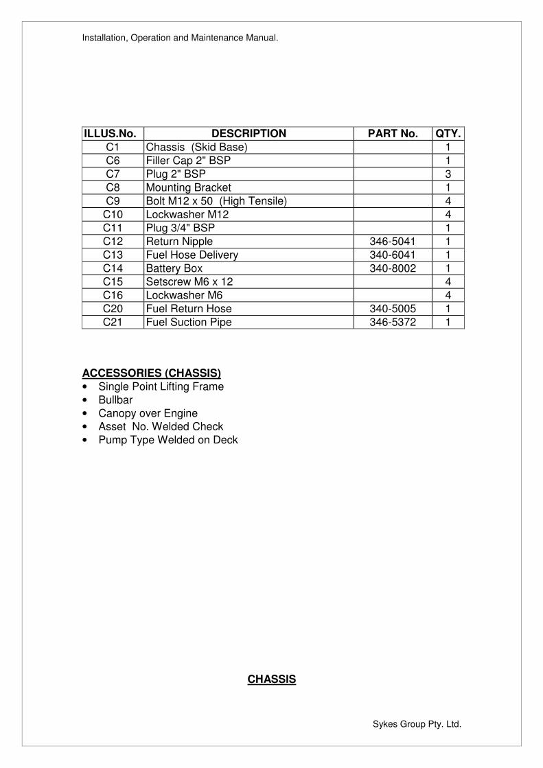
ILLUS.No. DESCRIPTION PART No. QTY. C1 Chassis (Skid Base) 1 C6 Filler Cap 2" BSP 1 C7 Plug 2" BSP 3 C8 Mounting Bracket 1 C9 Bolt M12 x 50 (High Tensile) 4
C10 Lockwasher M12 4 C11 Plug 3/4" BSP 1 C12 Return Nipple 346-5041 1 C13 Fuel Hose Delivery 340-6041 1 C14 Battery Box 340-8002 1 C15 Setscrew M6 x 12 4 C16 Lockwasher M6 4 C20 Fuel Return Hose 340-5005 1 C21 Fuel Suction Pipe 346-5372 1
ACCESSORIES (CHASSIS) • Single Point Lifting Frame • Bullbar • Canopy over Engine • Asset No. Welded Check • Pump Type Welded on Deck
CHASSIS
Installation, Operation and Maintenance Manual.
Sykes Group Pty. Ltd.
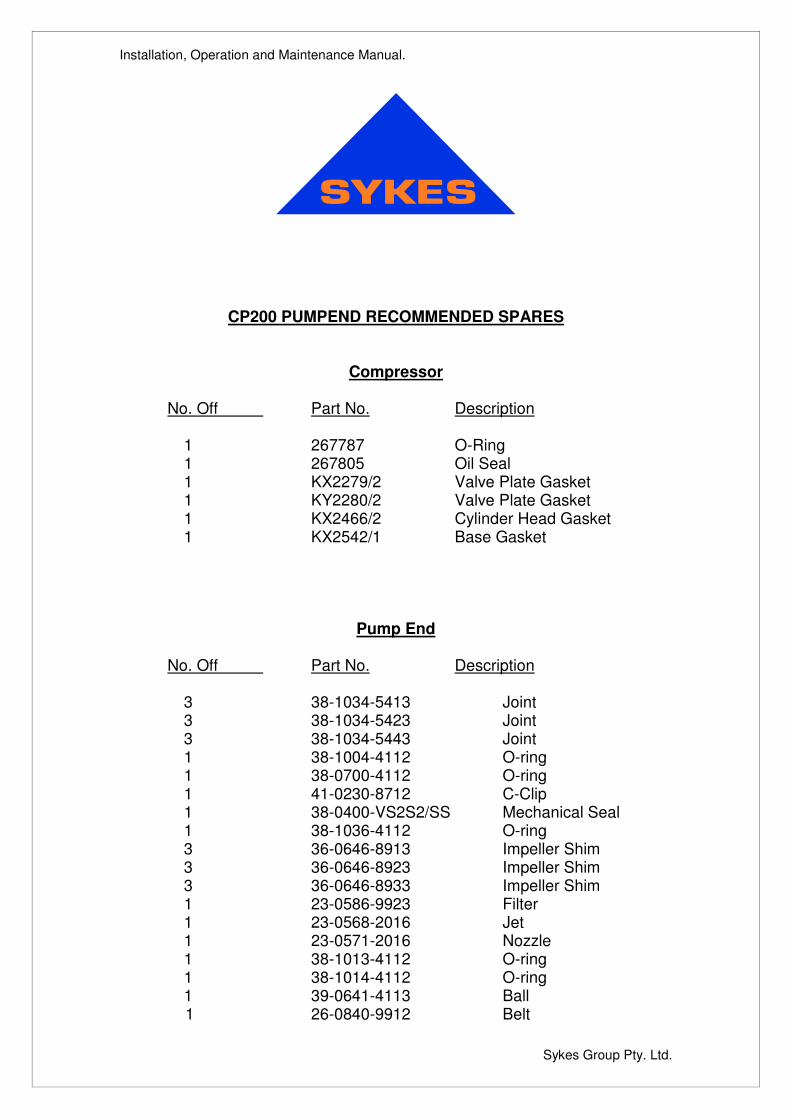
CP200 PUMPEND RECOMMENDED SPARES
Compressor
No. Off Part No. Description 1 267787 O-Ring 1 267805 Oil Seal 1 KX2279/2 Valve Plate Gasket 1 KY2280/2 Valve Plate Gasket 1 KX2466/2 Cylinder Head Gasket 1 KX2542/1 Base Gasket
Pump End No. Off Part No. Description 3 38-1034-5413 Joint 3 38-1034-5423 Joint 3 38-1034-5443 Joint 1 38-1004-4112 O-ring 1 38-0700-4112 O-ring 1 41-0230-8712 C-Clip 1 38-0400-VS2S2/SS Mechanical Seal 1 38-1036-4112 O-ring 3 36-0646-8913 Impeller Shim 3 36-0646-8923 Impeller Shim 3 36-0646-8933 Impeller Shim 1 23-0586-9923 Filter 1 23-0568-2016 Jet 1 23-0571-2016 Nozzle 1 38-1013-4112 O-ring 1 38-1014-4112 O-ring 1 39-0641-4113 Ball 1 26-0840-9912 Belt
Installation, Operation and Maintenance Manual.
Sykes Group Pty. Ltd.
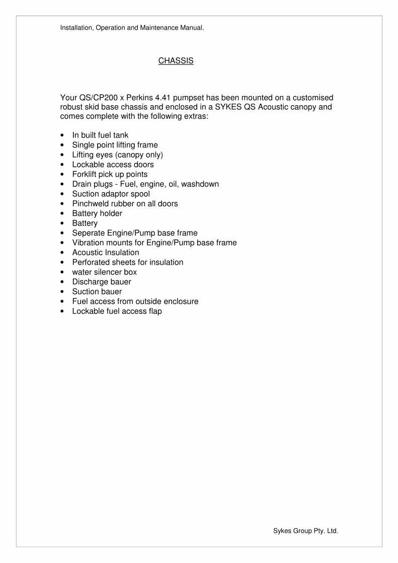
CHASSIS Your QS/CP200 x Perkins 4.41 pumpset has been mounted on a customised robust skid base chassis and enclosed in a SYKES QS Acoustic canopy and comes complete with the following extras: • In built fuel tank • Single point lifting frame • Lifting eyes (canopy only) • Lockable access doors • Forklift pick up points • Drain plugs - Fuel, engine, oil, washdown • Suction adaptor spool • Pinchweld rubber on all doors • Battery holder • Battery • Seperate Engine/Pump base frame • Vibration mounts for Engine/Pump base frame • Acoustic Insulation • Perforated sheets for insulation • water silencer box • Discharge bauer • Suction bauer • Fuel access from outside enclosure • Lockable fuel access flap
Installation, Operation and Maintenance Manual.
Sykes Group Pty. Ltd.
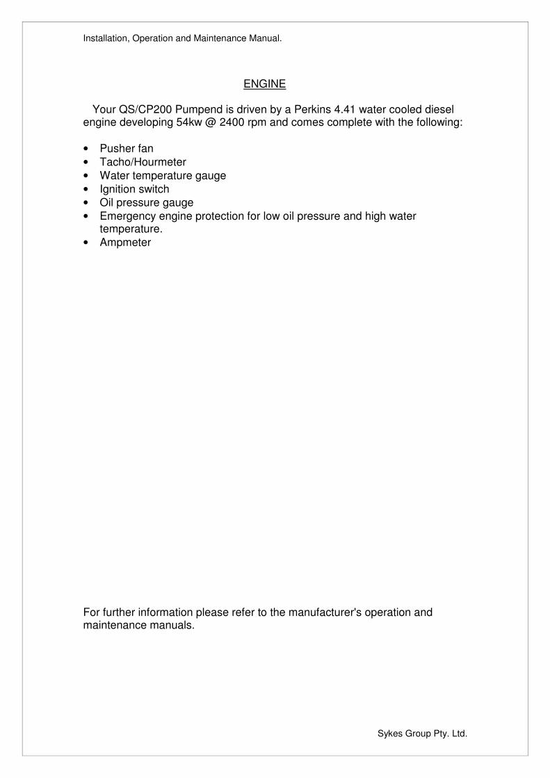
ENGINE Your QS/CP200 Pumpend is driven by a Perkins 4.41 water cooled diesel engine developing 54kw @ 2400 rpm and comes complete with the following: • Pusher fan • Tacho/Hourmeter • Water temperature gauge • Ignition switch • Oil pressure gauge • Emergency engine protection for low oil pressure and high water
temperature. • Ampmeter For further information please refer to the manufacturer's operation and maintenance manuals.