Embed Size (px)
Citation preview
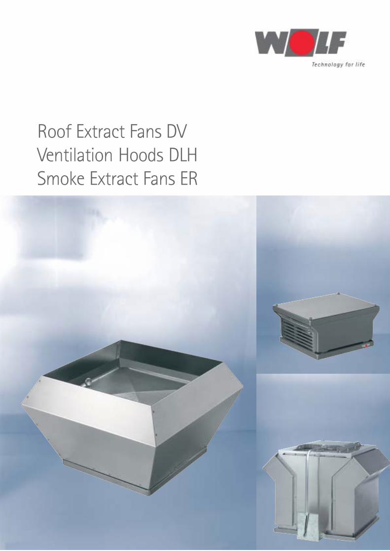
Roof Extract Fans DVVentilation Hoods DLHSmoke Extract Fans ER
2
Roof Extract Fans DVVentilation Hoods DLHSmoke Extract Fans ER
Summary .................................................................................................................. Seite
Roof Extract Fans DVProduct review ............................................................................................................................. 3
Summary data sheet .................................................................................................................. 4
General instructions ................................................................................................................... 5
Roof Extract Fan DV 30 ....................................................................................................... 6 - 7
Roof Extract Fan DV 40 ....................................................................................................... 8 - 9
Roof Extract Fan DV 56 ................................................................................................... 10 - 11
Roof Extract Fan DV 71 .................................................................................................. 12 - 13
Roof Extract Fan DV 90 .................................................................................................. 14 - 15
Roof Extract Fan DV 125 ............................................................................................... 16 - 17
Motor protection units ............................................................................................................ 18
Diagrams for control switches / diagrams for isolator switches .................................. 19
Diagrams for isolator switches .............................................................................................. 20
Control unit DigiPro .................................................................................................................. 21
Sample specification ............................................................................................................... 22
Roof Ventilation Hoods DLHProduct review .......................................................................................................................... 24
Dimensions ................................................................................................................................ 24
Pressure drops Intake – exhaust .......................................................................................... 24
Dimensions of accessories ..................................................................................................... 25
Smoke Extract Fans ERProduct review .......................................................................................................................... 26
Summary data sheet ............................................................................................................... 27
General instructions ....................................................................................................... 28 - 29
RDM 56/57-25.. – Performances / Dimensions ...................................................... 30 - 31
RDM 56/57-35.. – Performances / Dimensions ...................................................... 32 - 33
RDM 56/57-45.. – Performances / Dimensions ...................................................... 34 - 35
RDM 56/57-56.. – Performances / Dimensions ...................................................... 36 - 37
RDM 56/57-71.. – Performances / Dimensions ...................................................... 38 - 39
RDM 56/57-90.. – Performances / Dimensions ...................................................... 40 - 41
Isolator switches ....................................................................................................................... 42
Dimensions of accessories ..................................................................................................... 43
Sample specification ............................................................................................................... 44
3
Roof Extract Fans DV Technical Description
Motors
Well tried and tested integral drive motors are used. Noise-tested,maintenance-free deep-groove ball bearings give the motor longlife. To avoid overheating, every motor is equipped with thermalcontacts. This thermal protection has to be effective in operationin order to enable the user to claim for warranty in the case ofbreak down. Please follow the instructions of the wiring diagramfor connecting the thermal contacts correctly.
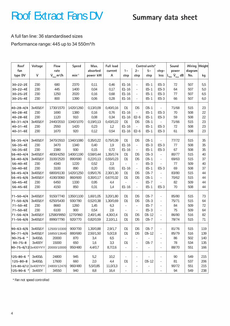
Fan range DV 40-125
The fans of the range DV 40 - 125, for vertical discharge, aresuitable for discharging slightly polluted but not aggressive air orvapours from - 20°C to app. + 40°C. The stylish casing and the baseplate are made of galvanised sheet steel. The centrifugal impellerwith backward curved blades is made of highly resistant aluminium.The exhaust air, due to the V-casing design, is rejected vertically farfrom the roof.All roof fans are equipped with an isolator switch ready forconnection.
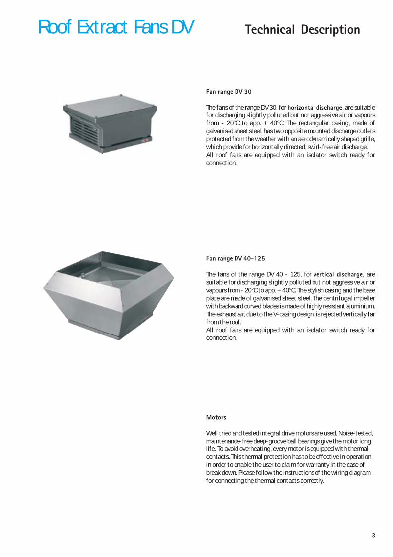
Fan range DV 30
The fans of the range DV 30, for horizontal discharge, are suitablefor discharging slightly polluted but not aggressive air or vapoursfrom - 20°C to app. + 40°C. The rectangular casing, made ofgalvanised sheet steel, has two opposite mounted discharge outletsprotected from the weather with an aerodynamically shaped grille,which provide for horizontally directed, swirl-free air discharge.All roof fans are equipped with an isolator switch ready forconnection.
4
Summary data sheet
Roof Voltage Flow Speed Max. Full load Control units* Sound Wiring Weightfan rate absorbed current 1- 2- 5- step- power diagram
type DV V Vmax m³/h min-1 power kW A step step step less LWA Vmax dB No. kg
30-22-2E 230 680 2370 0,11 0,46 E1-16 - E5-1 ES-3 72 507 5,530-22-4E 230 445 1400 0,04 0,17 E1-16 - E5-1 ES-3 64 507 5,030-25-2E 230 1250 2020 0,16 0,68 E1-16 - E5-1 ES-3 77 507 6,530-25-4E 230 800 1390 0,06 0,28 E1-16 - E5-1 ES-3 66 507 6,0
40-28-4/4 3x400∆Y 1730/1570 1420/1260 0,13/0,09 0,40/0,16 D1 DS D5-1 - 71/68 515 2340-28-4E 230 1690 1380 0,16 0,76 E1-16 - E5-1 ES-3 70 508 2240-28-6E 230 1120 910 0,08 0,34 E1-16 E2-6 E5-1 ES-3 59 508 2240-31-4/4 3x400∆Y 2440/2010 1340/1070 0,19/0,13 0,43/0,22 D1 DS D5-1 - 71/66 515 2340-31-4E 230 2550 1420 0,23 1,2 E1-16 - E5-1 ES-3 72 508 2340-31-6E 230 1670 920 0,12 0,54 E1-16 E2-6 E5-1 ES-3 61 508 23
56-35-4/4 3x400∆Y 3470/2910 1340/1080 0,35/0,22 0,75/0,39 D1 DS D5-1 - 77/72 515 3556-35-4E 230 3470 1340 0,40 1,9 E1-16 - E5-3 ES-3 77 508 3556-35-6E 230 2380 930 0,15 0,72 E1-16 - E5-1 ES-3 67 508 3556-40-4/4 3x400∆Y 4830/4250 1400/1190 0,58/0,44 1,35/0,74 D1 DS D5-3 - 80/77 515 4056-40-6/6 3x400∆Y 3100/2520 890/690 0,22/0,13 0,55/0,23 D1 DS D5-1 - 69/63 515 3756-40-4E 230 4340 1220 0,52 2,3 - - E5-3 - 77 509 4056-40-6E 230 3100 890 0,20 0,91 E1-16 - E5-1 ES-3 69 508 3756-45-4/4 3x400∆Y 6800/6130 1420/1250 0,95/0,76 2,30/1,30 D1 DS D5-7 - 83/80 515 4456-45-6/6 3x400∆Y 4190/3060 860/600 0,30/0,17 0,67/0,32 D1 DS D5-1 - 70/62 515 4456-45-4E 230 6450 1330 0,95 4,4 - - E5-7 - 82 509 4456-45-6E 230 4150 850 0,31 1,4 E1-16 - E5-1 ES-3 70 508 44
71-50-4/4 3x400∆Y 9150/7740 1350/1100 1,60/1,05 3,20/1,80 D1 DS D5-7 - 85/80 515 7371-50-6/6 3x400∆Y 6250/5430 930/780 0,52/0,38 1,30/0,69 D1 DS D5-3 - 75/71 515 6471-50-4E 230 8660 1260 1,45 6,3 - - E5-7 - 84 509 7271-50-6E 230 6100 900 0,54 2,6 - - E5-3 - 75 509 6471-56-4/4 3x400∆Y 12580/9950 1270/960 2,40/1,46 4,30/2,4 D1 DS D5-12 - 86/80 516 8271-56-6/6 3x400∆Y 8990/7790 920/770 0,82/0,59 2,10/1,1 D1 DS D5-7 - 78/74 515 71
90-63-6/6 3x400∆Y 12500/10300 900/700 1,30/0,88 2,9/1,7 D1 DS D5-7 - 81/76 515 11990-71-6/6 3x400∆Y 16850/13640 880/680 2,50/1,50 5,0/2,8 D1 DS D5-12 - 85/79 516 13990-75-6 * 3x400∆ 20000 870 3,4 6,5 - - - - 86 502 14090-75-8 3x400Y 15000 650 1,6 3,3 D1 - D5-7 - 78 534 135
90-75-6/12 3x400YY/Y 20000/10000 950/480 4,4/0,7 8,7/2,6 - - - - 88/70 551 166
125-80-6 * 3x400∆ 24800 945 5,2 10,2 - - - - 90 549 215125-80-8 3x400∆ 17600 660 2,0 4,4 D1 - D5-12 - 81 537 206
125-80-6/12 3x400YY/Y 24800/12470 960/480 5,5/0,85 11,0/3,3 - - - - 90/72 551 215125-90-6 * 3x400Y 34550 940 8,8 16,4 - - - - 94 549 238
* Fan not speed controlled
A full fan line: 36 standardised sizes
Performance range: 445 up to 34 550m³/h
Roof Extract Fans DV

5
All roof extract fans are supplied with a discharge-side mesh safety guard in accordancewith DIN EN 294. The inlet side is not fitted with a standard guard, because it is normalpractice to attach other system parts to the side. However, if the unit is installed in sucha way that accidental contact with the impeller is possible, an additional inlet guard has tobe fitted acc. to DIN EN 294! The fans may only be put into operation if all necessaryprotection devices are fitted and made effective (see maintenance instructions)! Thesafety guards are to be executed acc. to DIN EN 292 – 1, chapter 3.22 ”Separating safetydevices“ and DIN EN 292 – 2, chapter 4 ”Technical protection measures“.
Transport, fitting, electrical connection, start up, and maintenance are to be executedfollowing to the instructions given with the manual and by respecting the actual standards,guide lines, and safety rules.
The performance curves are obtained using an inlet side test chamber in accordance withDIN 24 163-2 ”Fans, performance tests, standard test equipment“. The performance gridsshow the effective pressure increase ∆pfa (Pressure increase obtained from the fan infree-field conditions) as a function of the flow volume VL.Reference media density: ρ1 = 1.15 kg/m³. The roof fans comply with the tolerances ofClass 2 of DIN 24 166 ”Fans, Technical Specifications“.
Measurement and evaluation of noise levels are in accordance with DIN 45 635 - 38“Sound measurements on machines; fans”. In the technical data the A-weighted soundpower level at maximum flow rate is given.
The computer aided data collection and evaluation enables to obtain highly reliable dataprecision. In the curves the emission value of the A-sound-power level LWA is given,having the same value for intake (LWA3) as for the discharge (LWA8).For more exact calculations when determining the required attenuation, the sound powerlevel in the octave bands is important.
LWoct 3/8= LWA + LWrel 3/8
The relative sound power levels for inlet and discharge sides, at various duty points, can beread from the corresponding tables.
Because conditions in the operating environment are usually far from ideal formeasurement and can vary greatly, a determination of the A-sound-pressure level at anydistance is only possible with great uncertainty.
LPA ≈ LWA – ∆ L
The diagram on the left side supplies the correction value ”∆L“ in function of the distance”r“ from the fan centre. Under ideal conditions, with a clear hemisphere of soundpropagation, curve ”a“ is valid. However, curve ”b“ is recommended for practical estimates.The calculation of the intake sound-power level is only possible if the exact noiseparameters of the connected room are known (see VDI 2081!).
Due to turbulences generated by the back draught damper the sound data for intake anddischarge may increase by app. 3 dB at discharge when a damper is fitted.It is recommended to provide a duct section between fan and damper because under thisconfiguration the indicated pressure drops are applicable.If the damper is directly fitted to the fan higher pressure losses have to be expected.
General instructions
Safety Guards
Safety instructions
Performance data
Sound Data
Influence of the back draught damper
r
10
20
30dB
1 5 10mr
ab
Roof Extract Fans DV
6
Performance Data DV 30
Roof Voltage Flow Speed Absorbed Full load Control units* Sound Wiring Weightfan rate power current 1- 2- 5- step- power diagram
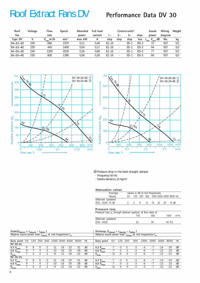
Type DV V Vmax m³/h min-1 max kW A step step step less LWA Vmax dB No. kg30-22-2E 230 680 2370 0,11 0,46 E1-16 - E5-1 ES-3 72 507 5,530-22-4E 230 445 1400 0,04 0,17 E1-16 - E5-1 ES-3 64 507 5,030-25-2E 230 1250 2020 0,16 0,68 E1-16 - E5-1 ES-3 77 507 6,530-25-4E 230 800 1390 0,06 0,28 E1-16 - E5-1 ES-3 66 507 6,0
Pressure drop in the back draught damper- Frequency 50 Hz- Media density1,15 kg/m³
Attenuation valuesAverage values in dB at mid frequenciesValues 63 125 250 500 1000 2000 4000 8000 Hz
Silencer upstandZDS..-0028 16 dB 2 5 8 12 18 22 20 15 dB
Pressure lossPressure loss pA through silencer upstand, at flow rates of
750 900 1000 m³/hSilencer upstandZDS..-0028 22 30 40 Pa
Intake(LWrel3 = LWoct3 - LWA3 ) Discharge (LWrel8 = LWoct8 - LWA8 )Relative sound power level LWrel3 at mid frequencies fm Relative sound power level LWrel8 at mid frequencies fm
Duty point 63 125 250 500 1000 2000 4000 8000 Hz Duty point 63 125 250 500 1000 2000 4000 8000 HzDV 30-220,3 Vmax 9 9 5 -2 -11 -18 -22 -31 dB 0,3 Vmax -7 -3 0 -3 -6 -7 -14 -24 dB0,6 Vmax 9 7 4 -2 -10 -16 -20 -28 dB 0,6 Vmax -7 -4 -2 -3 -6 -7 -13 -23 dBVmax 7 4 2 -1 -9 -12 -16 -22 dB Vmax -11 -5 -4 -4 -5 -7 -12 -21 dBDV 30-250,3 Vmax 9 9 5 -2 -11 -18 -22 -31 dB 0,3 Vmax -7 -3 0 -3 -6 -7 -14 -24 dB0,6 Vmax 9 7 4 -2 -10 -16 -20 -28 dB 0,6 Vmax -7 -4 -2 -3 -6 -7 -13 -23 dBVmax 7 4 2 -1 -9 -12 -16 -22 dB Vmax -11 -5 -4 -4 -5 -7 -12 -21 dB
100 200 300 4000 m³/h
250
50
200
0
PaDV 30-22-2EDV 30-22-4E
500
150
300
100
600
350
400
LW
A 74dB
73
70
70
7264
59
62
12
1
2
m³/s0 0,05 0,1 0,15
*
200 400 600 8000 m³/h
200
0
PaDV 30-25-2EDV 30-25-4E
1000
300
100
1200
LW
A78
dB
500
400
76
72
74
77
67
63
66
12
1
2
m³/s0 0,1 0,2 0,3
*
Ava
ilabl
e pr
essu
re ∆
p fa
Flow rate V
*
Roof Extract Fans DV
Ava
ilabl
e pr
essu
re ∆
p fa
Flow rate V
7
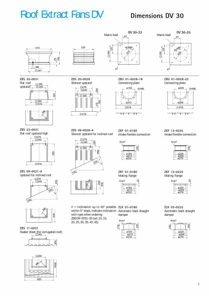
Dimensions DV 30
ø7
213
341M6
410 330
97
6×M6
ø7
259
6×M6
97
DV 30-22 DV 30-25
300
245295
M6
610
ZBS 23-0031Flat roof upstand high
278
518
245
ZBS 09-0031-#Upstand für inclined roof
150
150
278245
M6
ZBS 11-0031Soaker sheet (for corrugated roof)
920
290
M6
ZBS 20-0031Flat roofupstand
ZDS 20-0028Silencer upstand
150
150
278245
190
M6
ZDS 09-0028-#Silencer upstand for inclined roof
ZBU 01-0028-18Connecting plate
ø183
ø213
6×M6
518
ZBU 01-0028-22Connecting plate
ø229
ø259
6×M6
518
ZKF 01-0180Intake flexible connection
ZKF 13-0225Intake flexible connection
6×ø7
ø213ø233
ø183
6×ø7
ø259ø279
ø229
ZKF 01-0180Mating flange
ZKF 13-0225Mating flange
6×ø7
ø213ø233
ø183
6×ø7
ø259ø279
ø229
ZLK 01-0180Automatic back draughtdamper
ZLK 03-0225Automatic back draughtdamper
6×ø7
ø213ø233
ø183
6×ø7
ø259ø279
ø229
Mains lead Mains lead
# = inclination up to 45° possiblewithin 5° steps. Indicate inclinationwith type when orderingZBS 09-0031-05 (od. 10, 15,20, 25, 30, 35, 40, 45)
518
765
250
115
278245
190
Roof Extract Fans DV
8
Performance Data DV 40
Roof Voltage Flow Speed Absorbed Full load Control units* Sound Wiring Weightfan rate power current 1- 2- 5- step- power diagram
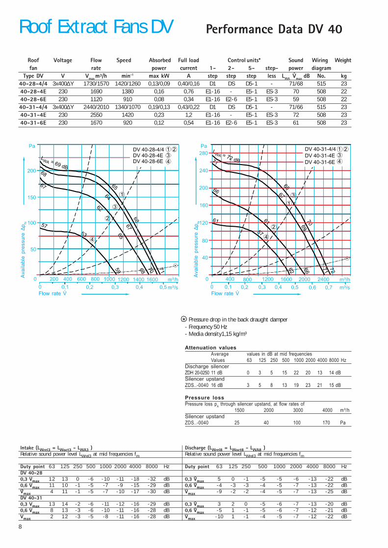
Type DV V Vmax m³/h min-1 max kW A step step step less LWA Vmax dB No. kg40-28-4/4 3x400∆Y 1730/1570 1420/1260 0,13/0,09 0,40/0,16 D1 DS D5-1 - 71/68 515 2340-28-4E 230 1690 1380 0,16 0,76 E1-16 - E5-1 ES-3 70 508 2240-28-6E 230 1120 910 0,08 0,34 E1-16 E2-6 E5-1 ES-3 59 508 2240-31-4/4 3x400∆Y 2440/2010 1340/1070 0,19/0,13 0,43/0,22 D1 DS D5-1 - 71/66 515 2340-31-4E 230 2550 1420 0,23 1,2 E1-16 - E5-1 ES-3 72 508 2340-31-6E 230 1670 920 0,12 0,54 E1-16 E2-6 E5-1 ES-3 61 508 23
Pressure drop in the back draught damper- Frequency 50 Hz- Media density1,15 kg/m³
Attenuation valuesAverage values in dB at mid frequenciesValues 63 125 250 500 1000 2000 4000 8000 Hz
Discharge silencerZDH 20-0250 11 dB 0 3 5 15 22 20 13 14 dBSilencer upstandZDS..-0040 16 dB 3 5 8 13 19 23 21 15 dB
Pressure lossPressure loss pA through silencer upstand, at flow rates of
1500 2000 3000 4000 m³/hSilencer upstandZDS..-0040 25 40 100 170 Pa
Intake (LWrel3 = LWoct3 - LWA3 ) Discharge (LWrel8 = LWoct8 - LWA8 )Relative sound power level LWrel3 at mid frequencies fm Relative sound power level LWrel3 at mid frequencies fm
Duty point 63 125 250 500 1000 2000 4000 8000 Hz Duty point 63 125 250 500 1000 2000 4000 8000 HzDV 40-280,3 Vmax 12 13 0 -6 -10 -11 -18 -32 dB 0,3 Vmax 5 0 -1 -5 -5 -6 -13 -22 dB0,6 Vmax 11 10 -1 -5 -7 -9 -15 -29 dB 0,6 Vmax -4 -3 -3 -4 -5 -7 -13 -22 dBVmax 4 11 -1 -5 -7 -10 -17 -30 dB Vmax -9 -2 -2 -4 -5 -7 -13 -25 dBDV 40-310,3 Vmax 13 14 -2 -6 -11 -12 -16 -29 dB 0,3 Vmax 3 2 0 -5 -6 -7 -13 -20 dB0,6 Vmax 8 13 -3 -6 -10 -11 -16 -28 dB 0,6 Vmax -5 1 -1 -5 -6 -7 -12 -21 dBVmax 2 12 -3 -5 -8 -11 -16 -28 dB Vmax -10 1 -1 -4 -5 -7 -12 -22 dB
DV 40-28-4/4DV 40-28-4EDV 40-28-6E
Pa
200
150
100
50
0 200 1000 1200 m³/h
m³/s0 0,1 0,2 0,3 0,4
134
2
1
3
4
2
LWA = 69 dB
65
68
71
68
64
67
67
62
65
6
57
53
5
89
400 600 800 1400 1600
0,5
*07
DV 40-31-4/4
DV 40-31-4E
DV 40-31-6E
Pa
200
40
120
160
0 400 1200800 1600 2000 m³/h
m³/s0 0,1 0,2 0,3 0,4 0,5 0,6 0,7
80
*
134
2
1
3
4
2
LWA = 72 dB
68
70
72
71
67
69
71
66
61
66
61
57
62
2400
280
240
*
Roof Extract Fans DV
Flow rate V
Ava
ilabl
e pr
essu
re ∆
p fa
Flow rate V
Ava
ilabl
e pr
essu
re ∆
p fa
9
ø12
286
440M6
671
6×M6
138
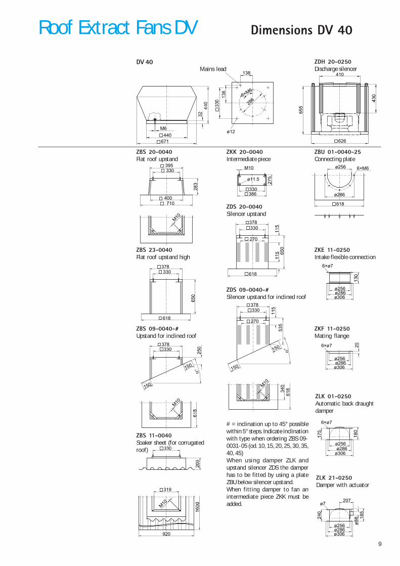
DV 40
ZBS 23-0040Flat roof upstand high
ZBS 09-0040-#Upstand for inclined roof
ZBS 11-0040Soaker sheet (for corrugatedroof)
ZBS 20-0040Flat roof upstand
ZDS 20-0040Silencer upstand
ZDS 09-0040-#Silencer upstand for inclined roof
ZKK 20-0040Intermediate piece
ZBU 01-0040-25Connecting plate
ZKE 11-0250Intake flexible connection
ZKF 11-0250Mating flange
ZLK 21-0250Damper with actuator
ZLK 01-0250Automatic back draughtdamper
Mains leadZDH 20-0250Discharge silencer
626
410
400
330395
M10
710
ø11.5
330386
M10 ø256
ø286
6×M6
618
378
618
330
150
150
378330
M10
920
319
M10
6×ø7
ø286ø306
ø256
6×ø7
ø286ø306
ø256
# = inclination up to 45° possiblewithin 5° steps. Indicate inclinationwith type when ordering ZBS 09-0031-05 (od. 10, 15, 20, 25, 30, 35,40, 45)When using damper ZLK andupstand silencer ZDS the damperhas to be fitted by using a plateZBU below silencer upstand.When fitting damper to fan anintermediate piece ZKK must beadded. ø7
207
18
5
ø286ø306
ø256
150
150
378330
270
535
340
618
M10
618
65
0
378330
270
6×ø7
ø286ø306
ø256
18
0
Roof Extract Fans DV Dimensions DV 40

10
Performance Data DV 56
Roof Voltage Flow Speed Absorbed Full load Control units* Sound Wiring Weightfan rate power current 1- 2- 5- step- power diagram
Type DV V Vmax m³/h min-1 max kW A step step step less LWA Vmax dB No. kg56-35-4/4 3x400∆Y 3470/2910 1340/1080 0,35/0,22 0,75/0,39 D1 DS D5-1 - 77/72 515 3556-35-4E 230 3470 1340 0,40 1,9 E1-16 - E5-3 ES-3 77 508 3556-35-6E 230 2380 930 0,15 0,72 E1-16 - E5-1 ES-3 67 508 3556-40-4/4 3x400∆Y 4830/4250 1400/1190 0,58/0,44 1,35/0,74 D1 DS D5-3 - 80/77 515 4056-40-6/6 3x400∆Y 3100/2520 890/690 0,22/0,13 0,55/0,23 D1 DS D5-1 - 69/63 515 3756-40-4E 230 4340 1220 0,52 2,3 - - E5-3 - 77 509 4056-40-6E 230 3100 890 0,20 0,91 E1-16 - E5-1 ES-3 69 508 3756-45-4/4 3x400∆Y 6800/6130 1420/1250 0,95/0,76 2,30/1,30 D1 DS D5-7 - 83/80 515 4456-45-6/6 3x400∆Y 4190/3060 860/600 0,30/0,17 0,67/0,32 D1 DS D5-1 - 70/62 515 4456-45-4E 230 6450 1330 0,95 4,4 - - E5-7 - 82 509 4456-45-6E 230 4150 850 0,31 1,4 E1-16 - E5-1 ES-3 70 508 44
Pressure drop in the back draught damper- Frequency 50 Hz- Media density1,15 kg/m³
Attenuation valuesAverage values in dB at mid frequenciesValues 63 125 250 500 1000 2000 4000 8000 Hz
Discharge silencerZDH 20-0355 11 dB 0 3 5 15 22 20 13 14 dBSilencer upstandZDS..-0056 16 dB 3 5 8 12 18 21 20 15 dB
Pressure lossPressure loss pA through silencer upstand, at flow rates of
3000 4000 6000 8000 m³/hSilencer upstandZDS..-0056 25 42 80 160 Pa
Intake(LWrel3 = LWoct3 - LWA3 ) Discharge (LWrel8 = LWoct8 - LWA8 )Relative sound power level LWrel3 at mid frequencies fm Relative sound power level LWrel8 at mid frequencies fmDuty point 63 125 250 500 1000 2000 4000 8000 Hz Duty point 63 125 250 500 1000 2000 4000 8000 HzDV 56-350,3 Vmax 16 12 1 -3 -11 -15 -19 -28 dB 0,3 Vmax 4 1 -1 -4 -4 -8 -12 -21 dB0,6 Vmax 11 11 1 -3 -10 -11 -16 -26 dB 0,6 Vmax -3 -1 -3 -4 -5 -6 -12 -20 dBVmax 8 11 1 -2 -10 -11 -19 -25 dB Vmax -6 0 -3 -4 -5 -6 -15 -21 dBDV 56-400,3 Vmax 12 12 1 -3 -10 -15 -18 -28 dB 0,3 Vmax 5 2 0 -4 -4 -9 -13 -19 dB0,6 Vmax 11 11 0 -4 -8 -12 -16 -24 dB 0,6 Vmax 0 1 -1 -5 -5 -7 -11 -18 dBVmax 7 10 1 -3 -8 -12 -19 -20 dB Vmax -4 1 0 -4 -5 -8 -12 -15 dBDV 56-450,3 Vmax 12 13 -1 -6 -11 -15 -19 -27 dB 0,3 Vmax 5 3 -1 -4 -5 -9 -12 -17 dB0,6 Vmax 5 13 0 -6 -11 -14 -16 -25 dB 0,6 Vmax -2 2 0 -5 -6 -8 -10 -17 dBVmax 1 13 0 -5 -11 -14 -19 -20 dB Vmax -6 2 0 -4 -5 -8 -13 -15 dB
DV 56-35-4/4
DV 56-35-4E
DV 56-35-6E
Pa
200
150
100
50
0 500 1000 1500 2000 2500 m³/h
m³/s0 0,1 0,2 0,3 0,4 0,5 0,6 0,7
250
350
300
3000
0,8 0,9
3500
113
2
1
3
2
LWA = 74 dB
70
74
77
65
61
64
72
70
65
6967
1,0
*
DV 56-40-4/4
DV 56-40-6/6
DV 56-40-4E
DV 56-40-6E
Pa
200
100
0 1000 2000 m³/h
m³/s0 0,2 0,4 0,6 1,2
400
300
3000
0,8 1,0
4000
353
4
1
3
2
1 2
4
5
LWA = 79 dB
74
75
0
67
62
77
77
75
70
7469
61
56
6
76
70
773
8 *
DV 56-45-4/4
DV 56-45-6/6
DV 56-45-4E
DV 56-45-6E
Pa
200
100
0 1000 2000 m³/h
m³/s0 0,2 0,4 0,6 1,2
400
300
3000
0,8 1,0
4000 5000
1,4 1,6
6000
500
*
353
4
1
3
2
1 2
4
5
LWA = 82 dB
78
79
83
70
65
80
82
8074
77
70
61
56
62
81
76
80
*
Roof Extract Fans DVA
vaila
ble
pres
sure
∆p fa
Flow rate V
Ava
ilabl
e pr
essu
re ∆
p fa
Flow rate V
Ava
ilabl
e pr
essu
re ∆
p fa
Flow rate V
11
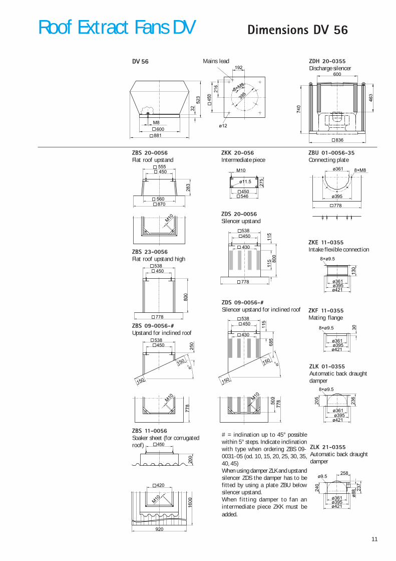
ø12
395
600M8
881
8×M8
192DV 56
ZBS 23-0056Flat roof upstand high
ZBS 09-0056-#Upstand for inclined roof
ZBS 11-0056Soaker sheet (for corrugatedroof)
ZBS 20-0056Flat roof upstand
ZDS 20-0056Silencer upstand
ZDS 09-0056-#Silencer upstand for inclined roof
ZKK 20-056Intermediate piece
ZBU 01-0056-35Connecting plate
ZKE 11-0355Intake flexible connection
ZKF 11-0355Mating flange
ZLK 21-0355Automatic back draughtdamper
ZLK 01-0355Automatic back draughtdamper
Mains lead ZDH 20-0355Discharge silencer
# = inclination up to 45° possiblewithin 5° steps. Indicate inclinationwith type when ordering ZBS 09-0031-05 (od. 10, 15, 20, 25, 30, 35,40, 45)When using damper ZLK and upstandsilencer ZDS the damper has to befitted by using a plate ZBU belowsilencer upstand.When fitting damper to fan anintermediate piece ZKK must beadded.
836
600
560
450555
M10
870
ø11.5
450546
M10 ø361
ø395
8×M8
778
538
778
450
8×ø9.5
ø395ø421
ø361
150
150
538450
M10
150
150
538450
430
M10
8×ø9.5
ø395ø421
ø361
920
420
M10
ø9.5258
ø395ø421
ø361
8×ø9.5
ø395ø421
ø361
23
6
20
5
778
800
538450
430
Roof Extract Fans DV Dimensions DV 56
12
Performance Data DV 71
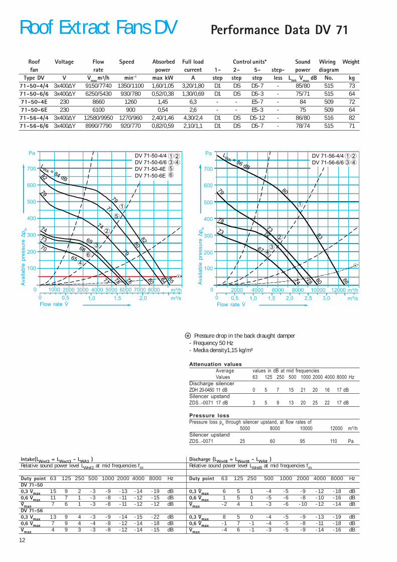
Roof Voltage Flow Speed Absorbed Full load Control units* Sound Wiring Weightfan rate power current 1- 2- 5- step- power diagram
Type DV V Vmax m³/h min-1 max kW A step step step less LWA Vmax dB No. kg71-50-4/4 3x400∆Y 9150/7740 1350/1100 1,60/1,05 3,20/1,80 D1 DS D5-7 - 85/80 515 7371-50-6/6 3x400∆Y 6250/5430 930/780 0,52/0,38 1,30/0,69 D1 DS D5-3 - 75/71 515 6471-50-4E 230 8660 1260 1,45 6,3 - - E5-7 - 84 509 7271-50-6E 230 6100 900 0,54 2,6 - - E5-3 - 75 509 6471-56-4/4 3x400∆Y 12580/9950 1270/960 2,40/1,46 4,30/2,4 D1 DS D5-12 - 86/80 516 8271-56-6/6 3x400∆Y 8990/7790 920/770 0,82/0,59 2,10/1,1 D1 DS D5-7 - 78/74 515 71
Intake(LWrel3 = LWoct3 - LWA3 ) Discharge (LWrel8 = LWoct8 - LWA8 )Relative sound power level LWrel3 at mid frequencies fm Relative sound power level LWrel8 at mid frequencies fm
Duty point 63 125 250 500 1000 2000 4000 8000 Hz Duty point 63 125 250 500 1000 2000 4000 8000 HzDV 71-500,3 Vmax 15 9 2 -3 -9 -13 -14 -19 dB 0,3 Vmax 6 5 1 -4 -5 -9 -12 -18 dB0,6 Vmax 11 7 1 -3 -8 -11 -12 -15 dB 0,6 Vmax 1 5 0 -5 -6 -8 -10 -16 dBVmax 7 6 1 -3 -8 -11 -12 -12 dB Vmax -2 4 1 -3 -6 -10 -12 -14 dBDV 71-560,3 Vmax 13 9 4 -3 -9 -14 -15 -22 dB 0,3 Vmax 8 5 0 -4 -5 -9 -13 -19 dB0,6 Vmax 7 9 4 -4 -8 -12 -14 -18 dB 0,6 Vmax -1 7 -1 -4 -5 -8 -11 -18 dBVmax 4 9 3 -3 -8 -12 -14 -15 dB Vmax -4 6 -1 -3 -5 -9 -14 -16 dB
Pressure drop in the back draught damper- Frequency 50 Hz- Media density1,15 kg/m³
Attenuation valuesAverage values in dB at mid frequenciesValues 63 125 250 500 1000 2000 4000 8000 Hz
Discharge silencerZDH 20-0450 11 dB 0 5 7 15 21 20 16 17 dBSilencer upstandZDS..-0071 17 dB 3 5 9 13 20 25 22 17 dB
Pressure lossPressure loss pA through silencer upstand, at flow rates of
5000 8000 10000 12000 m³/hSilencer upstandZDS..-0071 25 60 95 110 Pa
DV 71-50-4/4
DV 71-50-6/6
DV 71-50-4E
DV 71-50-6E
Pa
200
100
0 1000 2000 m³/h
m³/s0 0,5 1,5
400
300
3000
1,0
4000 5000
2,0
6000
500
600
700
7000 8000
*
356
4
1
3
2
1 2
4
5
6
LWA = 84 dB
79
80
8574
6882
84
79
74
79
75
70
65
71
82
77
80
73 69
75
DV 71-56-4/4
DV 71-56-6/6
Pa
200
100
0 2000 m³/h
m³/s0 0,5 1,5
400
300
1,0
4000 12000
2,0
6000
500
600
700
100008000
2,5 3,0
*
3 4
1
3
2
1 2
4
LWA = 86 dB
80
86
79
72 83
78
73
67
74
78
73
80
*
Roof Extract Fans DVA
vaila
ble
pres
sure
∆p fa
Flow rate V
Ava
ilabl
e pr
essu
re ∆
p fa
Flow rate V
13
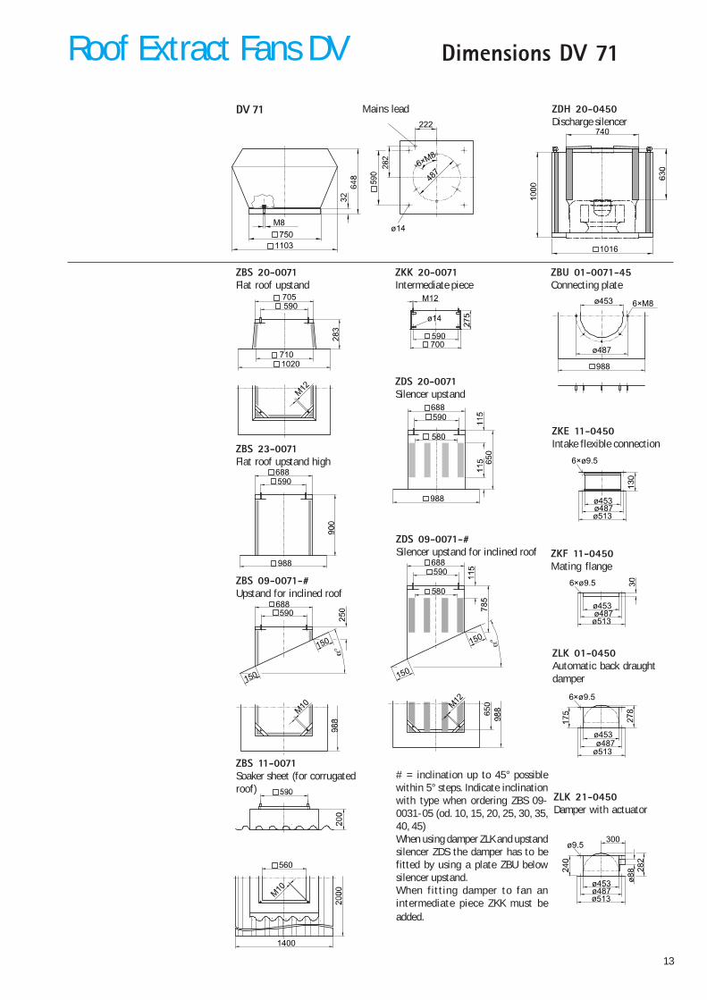
Dimensions DV 71
DV 71
ZBS 23-0071Flat roof upstand high
ZBS 09-0071-#Upstand for inclined roof
ZBS 11-0071Soaker sheet (for corrugatedroof)
ZBS 20-0071Flat roof upstand
ZDS 20-0071Silencer upstand
ZDS 09-0071-#Silencer upstand for inclined roof
ZKK 20-0071Intermediate piece
ZBU 01-0071-45Connecting plate
ZKE 11-0450Intake flexible connection
ZKF 11-0450Mating flange
ZLK 21-0450Damper with actuator
ZLK 01-0450Automatic back draughtdamper
Mains lead ZDH 20-0450Discharge silencer
# = inclination up to 45° possiblewithin 5° steps. Indicate inclinationwith type when ordering ZBS 09-0031-05 (od. 10, 15, 20, 25, 30, 35,40, 45)When using damper ZLK and upstandsilencer ZDS the damper has to befitted by using a plate ZBU belowsilencer upstand.When fitting damper to fan anintermediate piece ZKK must beadded.
ø14
487
750M8
1103
6×M8
222
1016
740
688
988
590
150
150
688590
M10
1400
560
M10
150
150
688590
580
M12
710
590705
M12
1020
ø14
590700
M12 ø453
ø487
6×M8
988
6×ø9.5
ø487ø513
ø453
6×ø9.5
ø487ø513
ø453
6×ø9.5
ø487ø513
ø453
ø9.5300
28
2
ø487ø513
ø453
988
65
0
688590
580
Roof Extract Fans DV
14
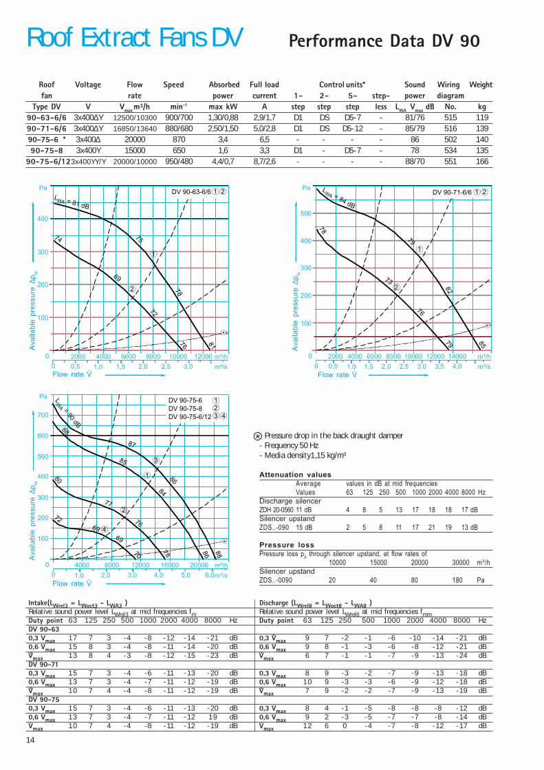
Performance Data DV 90
Roof Voltage Flow Speed Absorbed Full load Control units* Sound Wiring Weightfan rate power current 1- 2- 5- step- power diagram
Type DV V Vmax m³/h min-1 max kW A step step step less LWA Vmax dB No. kg90-63-6/6 3x400∆Y 12500/10300 900/700 1,30/0,88 2,9/1,7 D1 DS D5-7 - 81/76 515 11990-71-6/6 3x400∆Y 16850/13640 880/680 2,50/1,50 5,0/2,8 D1 DS D5-12 - 85/79 516 13990-75-6 * 3x400∆ 20000 870 3,4 6,5 - - - - 86 502 14090-75-8 3x400Y 15000 650 1,6 3,3 D1 - D5-7 - 78 534 135
90-75-6/123x400YY/Y 20000/10000 950/480 4,4/0,7 8,7/2,6 - - - - 88/70 551 166
Pressure drop in the back draught damper- Frequency 50 Hz- Media density1,15 kg/m³
Attenuation valuesAverage values in dB at mid frequenciesValues 63 125 250 500 1000 2000 4000 8000 Hz
Discharge silencerZDH 20-0560 11 dB 4 8 5 13 17 18 18 17 dBSilencer upstandZDS..-090 15 dB 2 5 8 11 17 21 19 13 dB
Pressure lossPressure loss pA through silencer upstand, at flow rates of
10000 15000 20000 30000 m³/hSilencer upstandZDS..-0090 20 40 80 180 Pa
Intake(LWrel3 = LWoct3 - LWA3 ) Discharge (LWrel8 = LWoct8 - LWA8 )Relative sound power level LWrel3 at mid frequencies fm Relative sound power level LWrel8 at mid frequencies fmmDuty point 63 125 250 500 1000 2000 4000 8000 Hz Duty point 63 125 250 500 1000 2000 4000 8000 HzDV 90-630,3 Vmax 17 7 3 -4 -8 -12 -14 -21 dB 0,3 Vmax 9 7 -2 -1 -6 -10 -14 -21 dB0,6 Vmax 15 8 3 -4 -8 -11 -14 -20 dB 0,6 Vmax 9 8 -1 -3 -6 -8 -12 -21 dBVmax 13 8 4 -3 -8 -12 -15 -23 dB Vmax 6 7 -1 -1 -7 -9 -13 -24 dBDV 90-710,3 Vmax 15 7 3 -4 -6 -11 -13 -20 dB 0,3 Vmax 8 9 -3 -2 -7 -9 -13 -18 dB0,6 Vmax 13 7 3 -4 -7 -11 -12 -19 dB 0,6 Vmax 10 9 -3 -3 -6 -9 -12 -18 dBVmax 10 7 4 -4 -8 -11 -12 -19 dB Vmax 7 9 -2 -2 -7 -9 -13 -19 dBDV 90-750,3 Vmax 15 7 3 -4 -6 -11 -13 -20 dB 0,3 Vmax 8 4 -1 -5 -8 -8 -8 -12 dB0,6 Vmax 13 7 3 -4 -7 -11 -12 19 dB 0,6 Vmax 9 2 -3 -5 -7 -7 -8 -14 dBVmax 10 7 4 -4 -8 -11 -12 -19 dB Vmax 12 6 0 -4 -7 -8 -12 -17 dB
DV 90-63-6/6Pa
200
100
0 2000 m³/h
m³/s0 0,5 1,5
400
300
1,0
4000 12000
2,0
6000 100008000
2,5 3,0
*
1
2
1 2L
WA = 81 dB
75
81
74
78
72
69
76
DV 90-71-6/6Pa
200
100
0 2000 m³/h
m³/s0 0,5 1,5
400
300
1,0
4000 12000
2,0
6000 100008000
2,5 3,0
500
14000
3,5 4,0
*
1
2
1 2LWA = 84 dB
79
85
78
82
73
79
76
DV 90-75-6
DV 90-75-8
DV 90-75-6/12
Pa
200
100
0 4000 m³/h
m³/s0
400
300
1,0
8000
2,0
12000 16000
3,0
500
4,0
600
700
5,0 6,0
*
24
1
2
3
1
3
LW
A =90
dB
87
88
80
69
86
70
72
8478
4
20000
76
85
86
88
69
77
*
Roof Extract Fans DVA
vaila
ble
pres
sure
∆p fa
Flow rate V
Ava
ilabl
e pr
essu
re ∆
p fa
Flow rate V
Ava
ilabl
e pr
essu
re ∆
p fa
Flow rate V
15
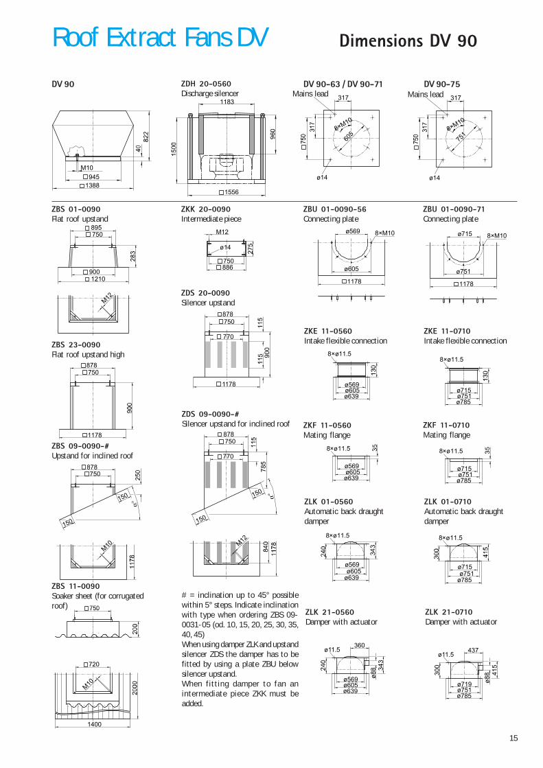
Dimensions DV 90
DV 90
ZBS 23-0090Flat roof upstand high
ZBS 09-0090-#Upstand for inclined roof
ZBS 11-0090Soaker sheet (for corrugatedroof)
ZBS 01-0090Flat roof upstand
ZDS 20-0090Silencer upstand
ZDS 09-0090-#Silencer upstand for inclined roof
ZKK 20-0090Intermediate piece
ZBU 01-0090-71Connecting plate
ZKE 11-0710Intake flexible connection
ZKF 11-0710Mating flange
ZLK 21-0710Damper with actuator
ZLK 01-0710Automatic back draughtdamper
Mains leadZDH 20-0560Discharge silencer
# = inclination up to 45° possiblewithin 5° steps. Indicate inclinationwith type when ordering ZBS 09-0031-05 (od. 10, 15, 20, 25, 30, 35,40, 45)When using damper ZLK and upstandsilencer ZDS the damper has to befitted by using a plate ZBU belowsilencer upstand.When fitting damper to fan anintermediate piece ZKK must beadded.
945M10
1388ø14
751
8×M10
317
ø14
605
8×M10
317 Mains lead
1556
1183
DV 90-63 / DV 90-71 DV 90-75
ZBU 01-0090-56Connecting plate
ZKE 11-0560Intake flexible connection
ZKF 11-0560Mating flange
ZLK 21-0560Damper with actuator
ZLK 01-0560Automatic back draughtdamper
150
150
878750
M10
1400
720
M10
878
1178
750
900
750895
M12
1210
ø14
750886
M12
150
150
878750
770
M12
ø569
ø605
8×M10
1178
ø715
ø751
8×M10
1178
8×ø11.5
ø605ø639
ø569
8×ø11.5
ø751ø785
ø715
8×ø11.5
ø605ø639
ø569
8×ø11.5
ø751ø785
ø715
8×ø11.5
ø605ø639
ø569
8×ø11.5
ø751ø785
ø715
ø11.5360
34
3
ø605ø639
ø569
ø11.5437
41
5
30
0
ø751ø785
ø719
1178
90
0
878750
770
Roof Extract Fans DV
16
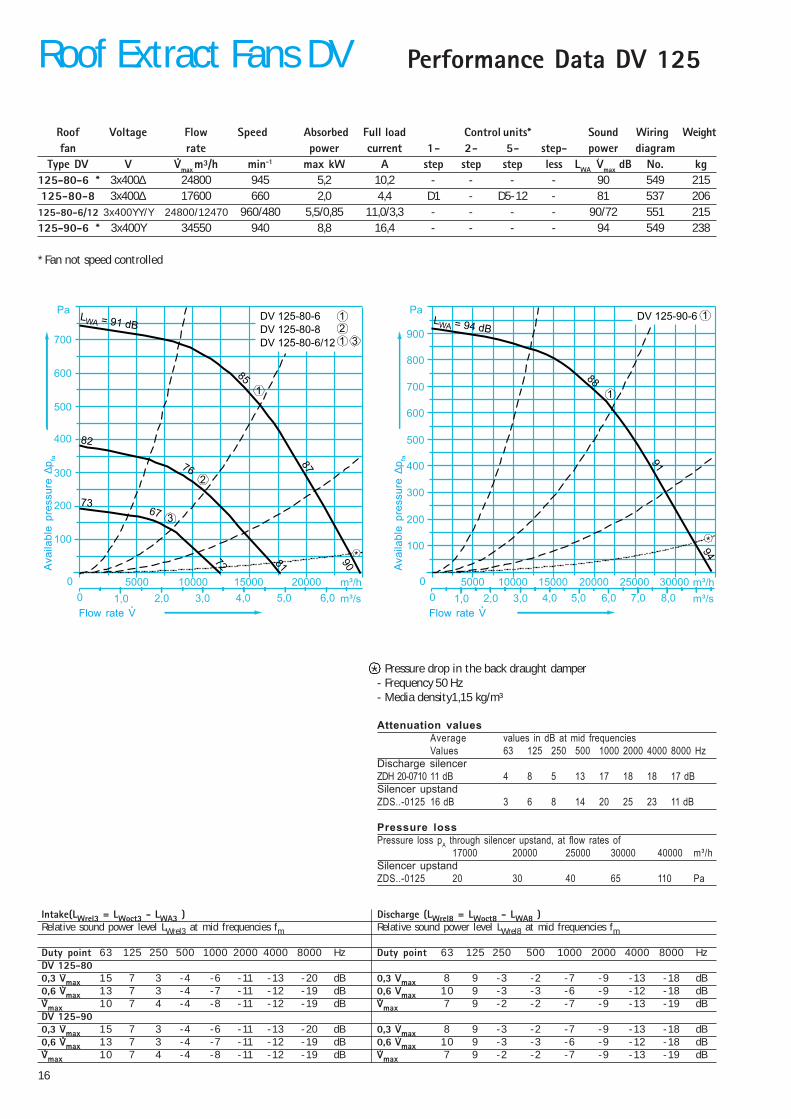
Performance Data DV 125
Roof Voltage Flow Speed Absorbed Full load Control units* Sound Wiring Weightfan rate power current 1- 2- 5- step- power diagram
Type DV V Vmax m³/h min-1 max kW A step step step less LWA Vmax dB No. kg125-80-6 * 3x400∆ 24800 945 5,2 10,2 - - - - 90 549 215125-80-8 3x400∆ 17600 660 2,0 4,4 D1 - D5-12 - 81 537 206
125-80-6/12 3x400YY/Y 24800/12470 960/480 5,5/0,85 11,0/3,3 - - - - 90/72 551 215125-90-6 * 3x400Y 34550 940 8,8 16,4 - - - - 94 549 238
* Fan not speed controlled
Intake(LWrel3 = LWoct3 - LWA3 ) Discharge (LWrel8 = LWoct8 - LWA8 )Relative sound power level LWrel3 at mid frequencies fm Relative sound power level LWrel8 at mid frequencies fm
Duty point 63 125 250 500 1000 2000 4000 8000 Hz Duty point 63 125 250 500 1000 2000 4000 8000 HzDV 125-800,3 Vmax 15 7 3 -4 -6 -11 -13 -20 dB 0,3 Vmax 8 9 -3 -2 -7 -9 -13 -18 dB0,6 Vmax 13 7 3 -4 -7 -11 -12 -19 dB 0,6 Vmax 10 9 -3 -3 -6 -9 -12 -18 dBVmax 10 7 4 -4 -8 -11 -12 -19 dB Vmax 7 9 -2 -2 -7 -9 -13 -19 dBDV 125-900,3 Vmax 15 7 3 -4 -6 -11 -13 -20 dB 0,3 Vmax 8 9 -3 -2 -7 -9 -13 -18 dB0,6 Vmax 13 7 3 -4 -7 -11 -12 -19 dB 0,6 Vmax 10 9 -3 -3 -6 -9 -12 -18 dBVmax 10 7 4 -4 -8 -11 -12 -19 dB Vmax 7 9 -2 -2 -7 -9 -13 -19 dB
Pressure drop in the back draught damper- Frequency 50 Hz- Media density1,15 kg/m³
Attenuation valuesAverage values in dB at mid frequenciesValues 63 125 250 500 1000 2000 4000 8000 Hz
Discharge silencerZDH 20-0710 11 dB 4 8 5 13 17 18 18 17 dBSilencer upstandZDS..-0125 16 dB 3 6 8 14 20 25 23 11 dB
Pressure lossPressure loss pA through silencer upstand, at flow rates of
17000 20000 25000 30000 40000 m³/hSilencer upstandZDS..-0125 20 30 40 65 110 Pa
DV 125-80-6
DV 125-80-8
DV 125-80-6/12
Pa
200
100
0 5000 m³/h
m³/s0
400
300
1,0
10000
2,0
15000 20000
3,0
500
4,0
600
700
5,0 6,0
*
23
1
2
3
1
1
LWA = 91 dB
85
9082
67
87
72
73
76
81
DV 125-90-6Pa
200
100
0 5000 m³/h
m³/s0
400
300
1,0
10000
2,0
15000 20000
3,0
500
4,0
600
700
5,0 6,0
800
900
25000 30000
7,0 8,0
*
1
1LWA = 94 d
88
94
B
91
*
Roof Extract Fans DVA
vaila
ble
pres
sure
∆p fa
Flow rate V
Ava
ilabl
e pr
essu
re ∆
p fa
Flow rate V
17
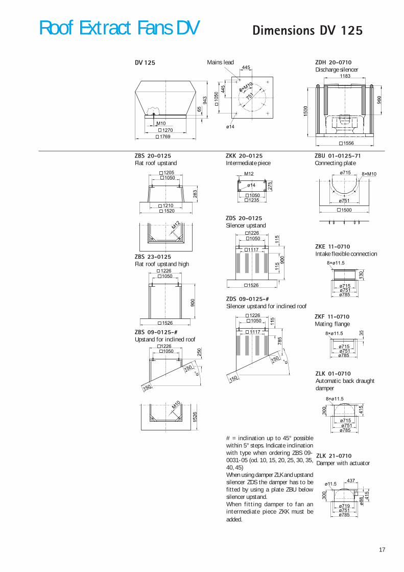
Dimensions DV 125
ø14
751
1270M10
1769
8×M10
445
1556
1183
DV 125
ZBS 23-0125Flat roof upstand high
ZBS 09-0125-#Upstand for inclined roof
ZBS 20-0125Flat roof upstand
ZDS 20-0125Silencer upstand
ZDS 09-0125-#Silencer upstand for inclined roof
ZKK 20-0125Intermediate piece
ZBU 01-0125-71Connecting plate
ZKE 11-0710Intake flexible connection
ZKF 11-0710Mating flange
ZLK 21-0710Damper with actuator
ZLK 01-0710Automatic back draughtdamper
Mains lead ZDH 20-0710Discharge silencer
# = inclination up to 45° possiblewithin 5° steps. Indicate inclinationwith type when ordering ZBS 09-0031-05 (od. 10, 15, 20, 25, 30, 35,40, 45)When using damper ZLK and upstandsilencer ZDS the damper has to befitted by using a plate ZBU belowsilencer upstand.When fitting damper to fan anintermediate piece ZKK must beadded.
1210
10501205
M12
1520
1226
1526
1050
150
150
12261050
M10
ø14
10501235
M12
1526
12261050
1117
150
150
12261050
1117
ø715
ø751
8×M10
1500
8×ø11.5
ø751ø785
ø715
8×ø11.5
ø751ø785
ø715
8×ø11.5
ø751ø785
ø715
ø11.5437
41
5
30
0
ø751ø785
ø719
Roof Extract Fans DV
18
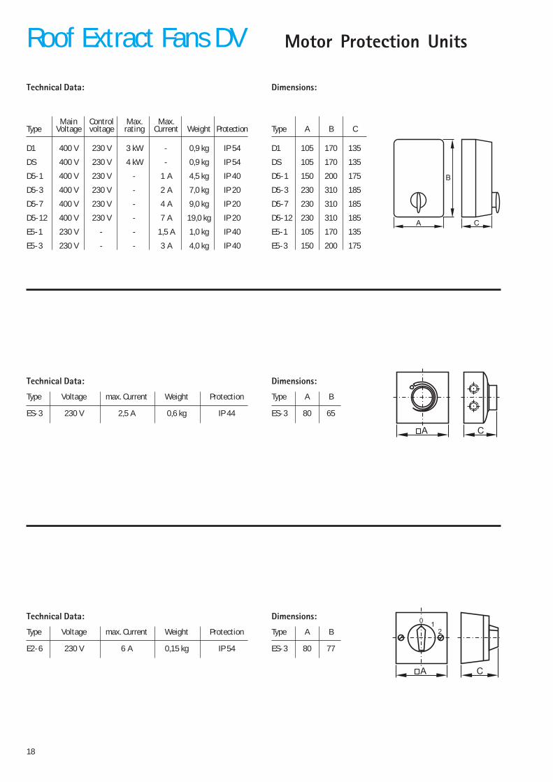
Technical Data:
Main Control Max. Max.Type Voltage voltage rating Current Weight Protection
D1 400 V 230 V 3 kW - 0,9 kg IP 54
DS 400 V 230 V 4 kW - 0,9 kg IP 54
D5-1 400 V 230 V - 1 A 4,5 kg IP 40
D5-3 400 V 230 V - 2 A 7,0 kg IP 20
D5-7 400 V 230 V - 4 A 9,0 kg IP 20
D5-12 400 V 230 V - 7 A 19,0 kg IP 20
E5-1 230 V - - 1,5 A 1,0 kg IP 40
E5-3 230 V - - 3 A 4,0 kg IP 40
Dimensions:
Type A B C
D1 105 170 135
DS 105 170 135
D5-1 150 200 175
D5-3 230 310 185
D5-7 230 310 185
D5-12 230 310 185
E5-1 105 170 135
E5-3 150 200 175
Motor Protection Units
Type Voltage max. Current Weight Protection
ES-3 230 V 2,5 A 0,6 kg IP 44
Type A B
ES-3 80 65
Technical Data: Dimensions:
Type Voltage max. Current Weight Protection
E2-6 230 V 6 A 0,15 kg IP 54
Type A B
ES-3 80 77
Technical Data: Dimensions:
A C
A C
01
2
A C
B
Roof Extract Fans DV
19
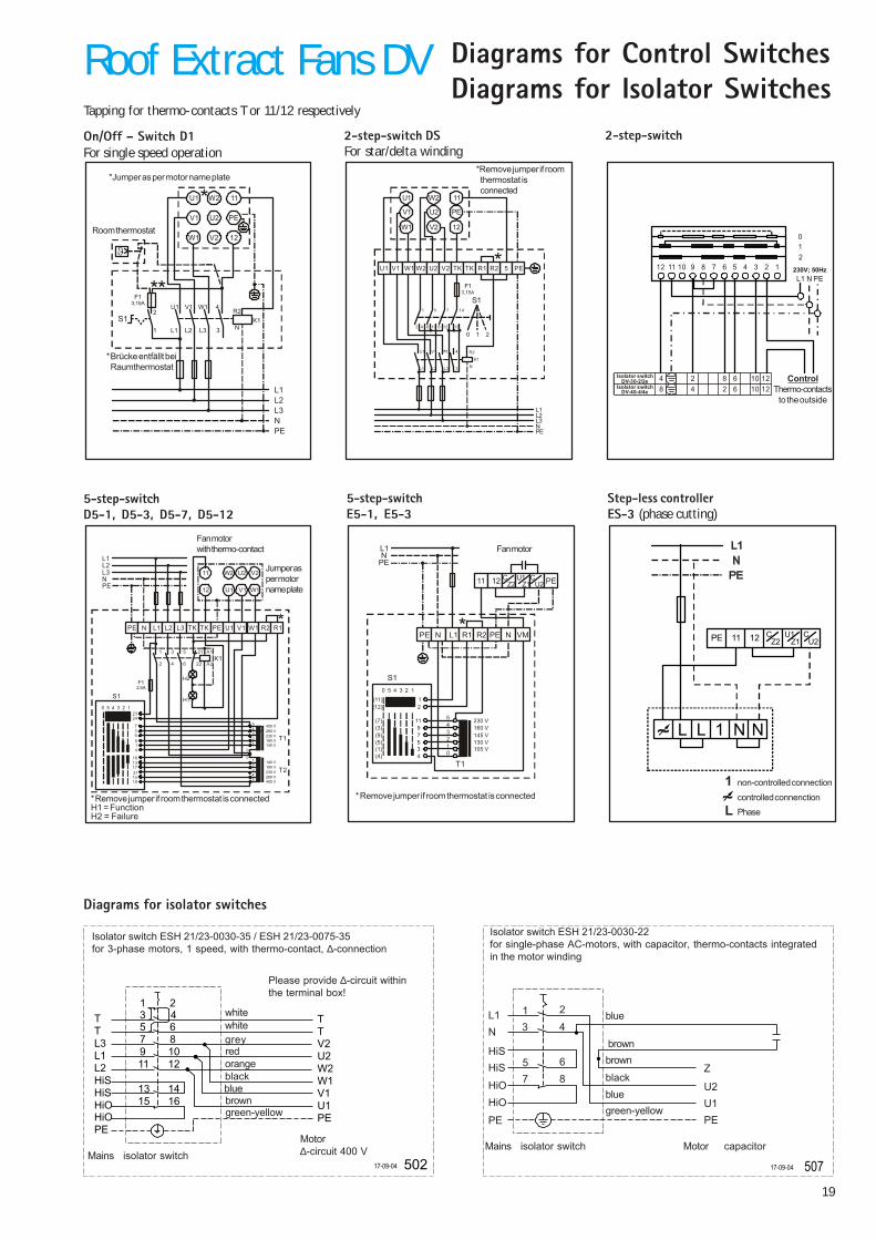
2-step-switch DSFor star/delta winding
L1L2L3NPE
V1 4
1
2 4 6 10 8 12 13
5 7 14
L1 L2 L3 3
210
R2
N
K1
S1
F13,15A
U1 V2V1 W1 TK TK R1 5R2 PEW2 U2
U1
V1
W1
W2
U2
V2
11
PE
12
*Remove jumper if roomthermostat isconnected
5-step-switchD5-1, D5-3, D5-7, D5-12
T1
T2
S1
400 V
140 V
280 V
180 V
230 V
230 V
180 V
280 V
140 V
400 V
H1
H2
K11
2
3
4
5
6
21
22
A1
A2
F12,5A
7
16
230 5 4 3 2 1
3
13
24
9
17
5
21
1
15
4
19
5
0
4
1
3
2
2
3
1
4
0
5
L1L2L3NPE
11
12
W2 U2 V2
U1 V1 W1
U1L2 L3 V1 W1TK TK R1R2PEPE N L1
Jumper asper motorname plate
Fan motorwith thermo-contact
*Remove jumper if room thermostat is connectedH1 = FunctionH2 = Failure
On/Off � Switch D1For single speed operation
PENL3L2L1
U12
1
U1
V1
W1
W2
U2
V2
11
PE
12
V1 W1 4R2
NK1
L1 L2 L3 3
S1
F13,15A
ϑ
*Jumper as per motor name plate
Room thermostat
*Brücke entfällt beiRaumthermostat
5-step-switchE5-1, E5-3
230 V160 V145 V130 V105 V
T1
S1
L1N
PE
11 12 PEC U1 CZ2 Z1 U2
11
10 5 4 3 2 1
9
2
7534
(7)
(11)
(3)
(12)
(9)(5)(1)(4)
543210
PE PEN N VML1 R1 R2
* Remove jumper if room thermostat is connected
Fan motor
Step-less controllerES-3 (phase cutting)
11 12PE
L L 1 N N
U1Z1
CU2Z2
C
1 non-controlled connection
controlled connenctionL Phase
2-step-switch
ControlThermo-contacts
to the outside
012
L1 N PE12
48
11 10 9
24
8 7 6
82
5
66
4 3
1010
2
12Isolator switch
DV-40-4/4e
Isolator switchDV-30-2/2e
12
1 230V; 50Hz
Diagrams for Control SwitchesDiagrams for Isolator Switches
TTL3L1L2HiSHiSHiOHiOPE
PEU1V1W1W2U2V2TT
15 1613 14
3 4
11 129 107 85 6
1 2
50217-09-04
Isolator switch ESH 21/23-0030-35 / ESH 21/23-0075-35for 3-phase motors, 1 speed, with thermo-contact, ∆-connection
Please provide ∆-circuit withinthe terminal box!
whitewhitegreyredorangeblackbluebrowngreen-yellow
Mains isolator switchMotor∆-circuit 400 V
50717-09-04
Z
U2
U1
PE
L1
N
HiS
HiS
HiO
HiO
PE
1
3
5
7 8
6
4
2
Isolator switch ESH 21/23-0030-22for single-phase AC-motors, with capacitor, thermo-contacts integratedin the motor winding
blue
brownbrown
blackbluegreen-yellow
Mains isolator switch Motor capacitor
Diagrams for isolator switches
Tapping for thermo-contacts T or 11/12 respectively
Roof Extract Fans DV
20
TTL2L1L3HiSHiSHiOHiOPE
PEU1V1W1W2U2V2T 6
81012
T 4
PEU1V1W1W2U2V2TT
15 1613 14
3 4
11 129 107 85 6
1 2
52705-08-02
509
T
T
L1
N
HiS
HiO
HiO
HiS
PE
Z2
Z1
U2
T
T
U1
PE
15 16
3 4
13 14
9 10
7 8
5 6
1 2
17-09-04
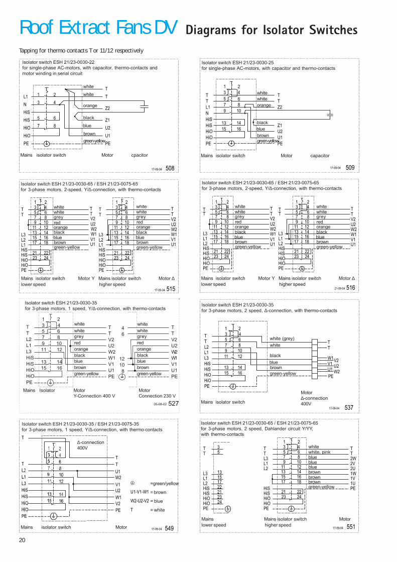
Isolator switch ESH 21/23-0030-25for single-phase AC-motors, with capacitor and thermo-contacts
whitewhiteorange
blackbluebrown
Mains isolator switch Motor capacitor
Diagrams for Isolator Switches
508
PE
U1
U2
Z1
T
T
Z2
21
65
87
43
PE
HiS
HiO
HiO
HiS
N
L1
17-09-04
Isolator switch ESH 21/23-0030-22for single-phase AC-motors, with capacitor, thermo-contacts andmotor winding in serial circuit
white
white
orange
black
blue
browngreen-yellow
Mains isolator switch Motor cpacitor
515
L2
L3
L1
PE
HiS
HiO
HiO
HiS
T
T
U1
V1
W1
W2
U2
V2
T
T
U1
V1
W1
W2
U2
V2
T
T
T
T
HiS
HiO
HiO
HiS
PE
L2
L3
L1
15
13
11
17
21
23
3
9
7
5
1
16
14
4
12
10
8
6
2
18
22
24
15
13
3
11
9
7
5
1
17
21
23
16
14
4
12
10
8
6
2
18
22
24
17-09-04
Isolator switch ESH 21/23-0030-65 / ESH 21/23-0075-65for 3-phase motors, 2-speed, Y/∆-connection, with thermo-contacts
whitewhitegreyredorangeblackbluebrowngreen-yellow
Mains isolator switch Motor Y Motor ∆Mainslower speed higher speed
isolator switch
whitewhitegreyredorangeblackbluebrowngreen-yellow
516
L1
L3
L2
PE
HiS
HiO
HiO
HiS
TT
L1
L3
L2
PE
HiS
HiO
HiO
HiS
TT
15
13
3
11
9
7
5
1
17
21
23
16
14
4
12
10
8
6
2
18
22
24
15
13
3
11
9
7
5
1
17
21
23
16
14
4
12
10
8
6
2
18
22
24
21-09-04
U1
V1
W1
W2
U2
V2
T
T
U1
V1
W1
W2
U2
V2
T
T
Isolator switch ESH 21/23-0030-65 / ESH 21/23-0075-65for 3-phase motors, 2-speed, Y/∆-connection, with thermo-contacts
whitewhitegreyredorangeblackbluebrowngreen-yellow
whitewhitegreyredorangeblackbluebrowngreen-yellow
Mains isolator switch Motor Y Motor ∆Mainslower speed higher speed
isolator switch
T
T
L2
L1
L3
HiS
HiS
HiO
HiO
PE
PE
U1
V1
W1
W2
U2
V2
T
T
15 16
13 14
3 4
11 12
9 10
7 8
5 6
1 2
53717-09-04
Mains isolator switch
Motor∆-connection400V
Isolator switch ESH 21/23-0030-35for 3-phase motors, 2 speed, ∆-connection, with thermo-contacts
white (grey)white
blackbluebrowngreen-yellow
549
U1
W1
V1
PE
W2
U2
V2
T
T
17-09-04
U1-V1-W1
W2-U2-V2
T
Isolator switch ESH 21/23-0030-35 / ESH 21/23-0075-35for 3-phase motors, 1 speed, Y/∆-connection, with thermo-contacts
Mains isolator switch Motor
∆-connection400V
=green/yellow
= brown
= blue
= white
551
L2
L3
L1
PE
HiS
HiO
HiO
HiS
T
T
PE
T
T
2W
2V
2U
1W
1V
1U17
15
13
L1
L3
L2
24
23
21
22
5
3
2423
2221
1817
21
65
87
109
1211
43
1413
1615
PE
HiS
HiO
HiO
HiS
T
T
17-09-04
Isolator switch ESH 21/23-0030-65 / ESH 21/23-0075-65for 3-phase motors, 2 speed, Dahlander circuit Y/YY,with thermo-contacts
white
blue
brown
green-yellow
Mains MotorMainslower speed higher speed
isolator switch
white, pink
blueblue
brownbrown
Tapping for thermo contacts T or 11/12 respectively
Roof Extract Fans DV
green-yellow
MotorY-Connection 400 V
Mains Isolator MotorConnection 230 V
Isolator switch ESH 21/23-0030-35for 3-phase motors, 1 speed, Y/∆-connection, with thermo-contacts
whitewhite
red
bluebrowngreen-yellow
grey
orangeblack
whitewhite
red
blue
grey
orangeblack
browngreen-yellow
21
DigiPro Control Unit
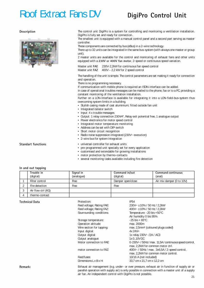
The control unit DigiPro is a system for controlling and monitoring a ventilation installation.DigiPro is fully set and ready for connection.The smallest unit is equipped with a manual control panel and a second part serving as mastercontroller.These components are connected by bus (eBus) in a 2-wire technology.There up to 32 units can be integrated in the same bus-system (with always one master or groupunit).2 master units are available for the control and monitoring of exhaust fans and other unitsequipped with a 230V or 400V fan motor, 2-speed or continuous speed variation.
Master unit FAE 230V-2,2kW for continuous fan speed controlMaster unit FAZ 400V – 2,2 kW for 2 speed control
The handling of the unit is simple. The control parameters are set making it ready for connectionand operation.There is no programming necessary.If communication with mobile phone is required an ISDN-interface can be added.In case of operational troubles messages can be mailed to the phone, fax or to a PC, providing aconstant monitoring of the ventilation installation.Further on a LON-Interface is available for integrating it into a LON-field-bus-system thusovercoming system limits in a building.• Stylish casing made of cast aluminium; fitted outside fan unit• Integrated isolator switch• Input: 4 x trouble messages• Output: 1 relay connection 230VH“, Relay exit potential free, 1 analogue output• Power electronics for motor speed control• Integrated motor temperature monitoring• Address can be set with DIP-switch• Short motor circuit recognition• Radio noise suppression integrated (230V~ execution)• 2-wire bus for system integration
• universal controller for exhaust units• pre-programmed unit specially set for every application• customised and extendable for growing installations• motor protection by thermo-contacts• several monitoring tasks available including fire detection
Description
Standart functions
Technical Data Protection: IP54Feed voltage; Rating FAE: 230V~ ±10% / 50 Hz / 2,2kWFeed voltage; Rating FAZ: 400V~ ±10% / 50 Hz / 2,2kWSourrounding conditions: Temperature: -20 bis +50°C
Air humidity 0 bis 95%Storage temperature: -25 bis + 65°COperation altitude: max. 2000mWire section for tapping: max. 2,5mm² (coloured plugs coded)Input digital: 4x 24V=Output digital: 1x relay 230V~ /2A / AC3Output analogue: 1x 0..10V DCMotor connection to FAE: 0-230V~ / 50Hz / max. 11,5A / continuous speed control,
max. 2,2kW for common motor ctrl.motor connection to FAZ: 400V~ / 50Hz / max. 3x6,5A / 2-speed control,
max. 2,2kW for common motor control.Feed fuses: 10/16 A (not included)Dimensions L x B x H: 33,7 cm x 21,7 cm x 12,2 cm
In and out tappingTrouble in Signal in Command in/out Command continuous(digital) (analogue) (digital) (anal)
1 Filter control Free Damper open/close Air mix damper (0 to 10V)
2 Fire detection Free Free
3 Air flow ctrl (KG)
4 thermo-contact
Remark: Exhaust air management (e.g. under- or over pressure, exhaust air in function of supply air orparallel operation with supply air) is only possible in connection with a master unit of a supplyair fan. An independent control with DigiPro is not possible.
Roof Extract Fans DV
22
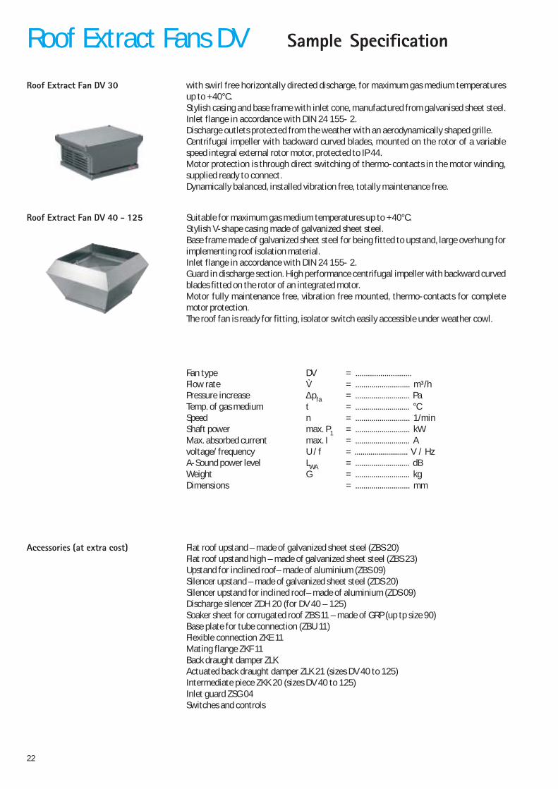
with swirl free horizontally directed discharge, for maximum gas medium temperaturesup to +40°C.Stylish casing and base frame with inlet cone, manufactured from galvanised sheet steel.Inlet flange in accordance with DIN 24 155- 2.Discharge outlets protected from the weather with an aerodynamically shaped grille.Centrifugal impeller with backward curved blades, mounted on the rotor of a variablespeed integral external rotor motor, protected to IP 44.Motor protection is through direct switching of thermo-contacts in the motor winding,supplied ready to connect.Dynamically balanced, installed vibration free, totally maintenance free.
Roof Extract Fan DV 30
Roof Extract Fan DV 40 - 125 Suitable for maximum gas medium temperatures up to +40°C.Stylish V-shape casing made of galvanized sheet steel.Base frame made of galvanized sheet steel for being fitted to upstand, large overhung forimplementing roof isolation material.Inlet flange in accordance with DIN 24 155- 2.Guard in discharge section. High performance centrifugal impeller with backward curvedblades fitted on the rotor of an integrated motor.Motor fully maintenance free, vibration free mounted, thermo-contacts for completemotor protection.The roof fan is ready for fitting, isolator switch easily accessible under weather cowl.
Fan type DV = ...........................Flow rate V = ........................... m³/hPressure increase ∆pfa = ........................... PaTemp. of gas medium t = ........................... °CSpeed n = ........................... 1/minShaft power max. P1 = ........................... kWMax. absorbed current max. I = ........................... Avoltage/ frequency U / f = ........................... V / HzA-Sound power level LWA = ........................... dBWeight G = ........................... kgDimensions = ........................... mm
Flat roof upstand – made of galvanized sheet steel (ZBS 20)Flat roof upstand high – made of galvanized sheet steel (ZBS 23)Upstand for inclined roof– made of aluminium (ZBS 09)Silencer upstand – made of galvanized sheet steel (ZDS 20)Silencer upstand for inclined roof– made of aluminium (ZDS 09)Discharge silencer ZDH 20 (for DV 40 – 125)Soaker sheet for corrugated roof ZBS 11 – made of GRP (up tp size 90)Base plate for tube connection (ZBU 11)Flexible connection ZKE 11Mating flange ZKF 11Back draught damper ZLKActuated back draught damper ZLK 21 (sizes DV 40 to 125)Intermediate piece ZKK 20 (sizes DV 40 to 125)Inlet guard ZSG 04Switches and controls
Accessories (at extra cost)
Sample SpecificationRoof Extract Fans DV
23
Summary ...................................................................................................................Page
Roof Ventilation Hoods DLHProduct review .......................................................................................................................... 24
Dimensions ................................................................................................................................. 24
Pressure drops Intake - exhaust ............................................................................................ 24
Dimensions of accessories ..................................................................................................... 25
Smoke Extract Fans ERProduct review .......................................................................................................................... 26
Summary data sheet ................................................................................................................ 27
Gerneral instructions ...................................................................................................... 28 - 29
RDM 56/57-25.. - Performances / Dimensions ........................................................ 30 / 31
RDM 56/57-35.. - Performances / Dimensions ....................................................... 32 - 33
RDM 56/57-45.. - Performances / Dimensions ....................................................... 34 - 35
RDM 56/57-56.. - Performances / Dimensions ....................................................... 36 - 37
RDM 56/57-71.. - Performances / Dimensions ........................................................ 38 - 39
RDM 56/57-90.. - Performances / Dimensions ....................................................... 40 - 41
Isolator switch ........................................................................................................................... 42
Dimensions of accessories ..................................................................................................... 43
Sample specification ................................................................................................................ 44
24
Roof Ventilation Hoods DLH
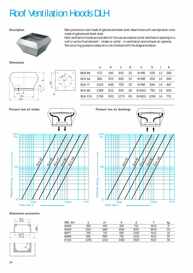
Rain protection cowl made of galvanized sheet steel. Base frame with aerodynamic conemade of galvanized sheet steel.Roof ventilation hoods are suitable for the use as weather proof ventilation opening in aroof or as the final element - intake or outlet - in ventilation and exhaust air systems.The occurring pressure losses are to be checked with the diagrams below.
ZBS 20- a a1 b d f kg0040 395 400 330 710 M10 80056 555 560 450 870 M10 100071 705 710 590 1020 M12 160090 895 900 750 1210 M12 250125 1205 1210 1050 1520 M12 34
øi
k
ce
a
α
a b c d e h i k
DLH 40 671 440 440 32 6×M6 330 12 286
DLH 56 881 523 600 32 8×M8 450 12 395
DLH 71 1103 648 750 32 6×M8 590 14 487
DLH 90 1388 822 940 40 8×M10 750 14 605
DLH 125 1769 933 1270 65 8×M10 1050 14 751
Dimensions
Pressure loss air intake Pressure loss air discharge
Dimensions accessories
Description
a1
ba
f
d
1000 m³/h10
Pa
10000
100
1000
DLH
40
DLH
56
DLH
71
DLH
90
DLH
125
Pre
ssur
e lo
ss p
A
1000 m³/h10
Pa
10000
100
1000
DLH
40
DLH
56
DLH
71
DLH
90
DLH
125
Pre
ssur
e lo
ss p
A
Flow rate V Flow rate V
25
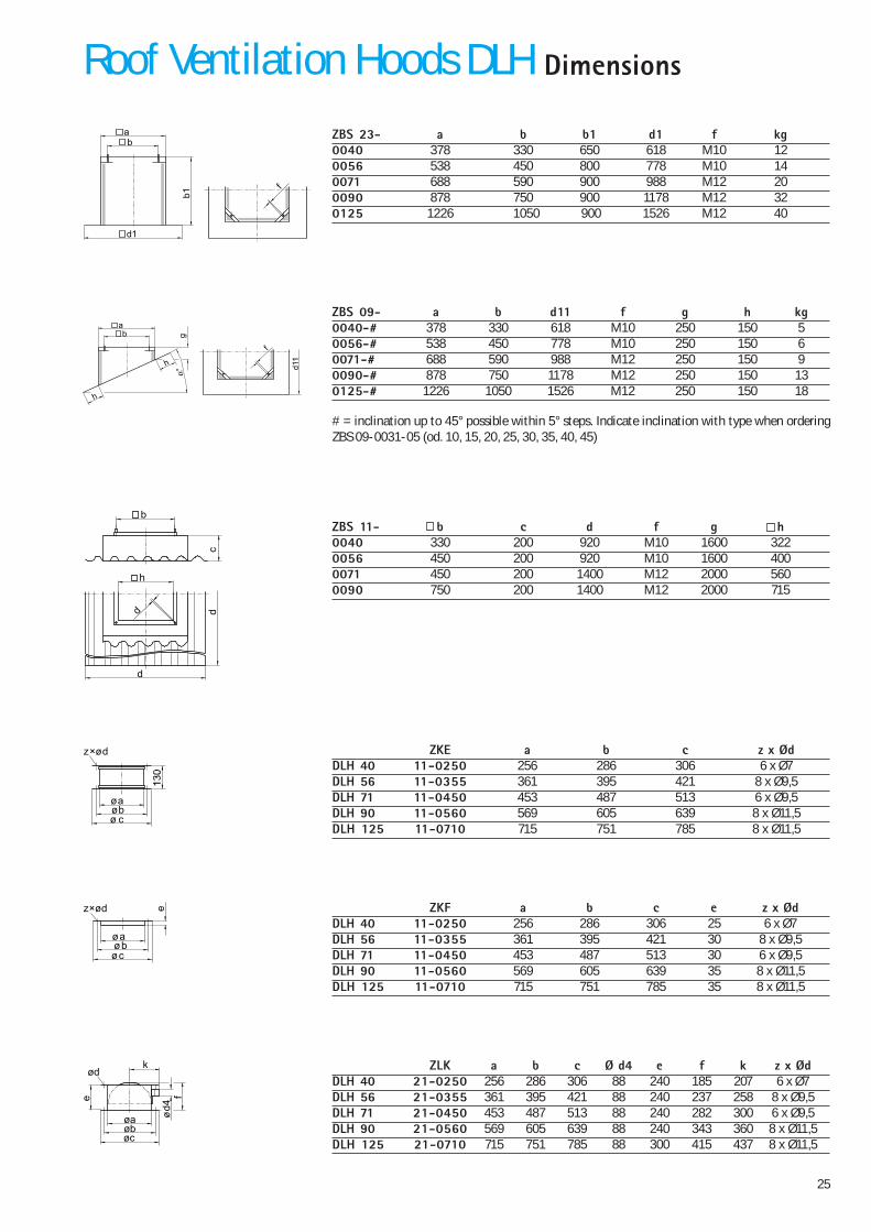
DimensionsRoof Ventilation Hoods DLH
ZKE a b c z x ØdDLH 40 11-0250 256 286 306 6 x Ø7DLH 56 11-0355 361 395 421 8 x Ø9,5DLH 71 11-0450 453 487 513 6 x Ø9,5DLH 90 11-0560 569 605 639 8 x Ø11,5DLH 125 11-0710 715 751 785 8 x Ø11,5
z×ød
øbcø
øa
ZKF a b c e z x ØdDLH 40 11-0250 256 286 306 25 6 x Ø7DLH 56 11-0355 361 395 421 30 8 x Ø9,5DLH 71 11-0450 453 487 513 30 6 x Ø9,5DLH 90 11-0560 569 605 639 35 8 x Ø11,5DLH 125 11-0710 715 751 785 35 8 x Ø11,5
z×ød
øbøc
øa
e
ZLK a b c Ø d4 e f k z x ØdDLH 40 21-0250 256 286 306 88 240 185 207 6 x Ø7DLH 56 21-0355 361 395 421 88 240 237 258 8 x Ø9,5DLH 71 21-0450 453 487 513 88 240 282 300 6 x Ø9,5DLH 90 21-0560 569 605 639 88 240 343 360 8 x Ø11,5DLH 125 21-0710 715 751 785 88 300 415 437 8 x Ø11,5
ødk
fe
d4
øbøc
øa
ZBS 11- b c d f g h0040 330 200 920 M10 1600 3220056 450 200 920 M10 1600 4000071 450 200 1400 M12 2000 5600090 750 200 1400 M12 2000 715
d
dd
c
h
b
ZBS 09- a b d11 f g h kg0040-# 378 330 618 M10 250 150 50056-# 538 450 778 M10 250 150 60071-# 688 590 988 M12 250 150 90090-# 878 750 1178 M12 250 150 130125-# 1226 1050 1526 M12 250 150 18
h
h
ab g
d11
f
# = inclination up to 45° possible within 5° steps. Indicate inclination with type when orderingZBS 09-0031-05 (od. 10, 15, 20, 25, 30, 35, 40, 45)
ZBS 23- a b b1 d1 f kg0040 378 330 650 618 M10 120056 538 450 800 778 M10 140071 688 590 900 988 M12 200090 878 750 900 1178 M12 320125 1226 1050 900 1526 M12 40
a
d1
b1
b
f
26
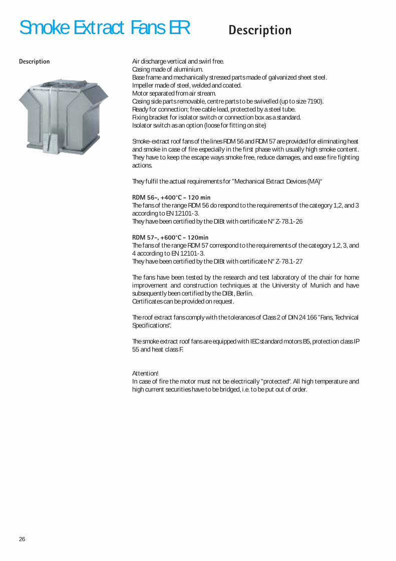
Description Air discharge vertical and swirl free.Casing made of aluminium.Base frame and mechanically stressed parts made of galvanized sheet steel.Impeller made of steel, welded and coated.Motor separated from air stream.Casing side parts removable, centre parts to be swivelled (up to size 7190).Ready for connection; free cable lead, protected by a steel tube.Fixing bracket for isolator switch or connection box as a standard.Isolator switch as an option (loose for fitting on site)
Smoke-extract roof fans of the lines RDM 56 and RDM 57 are provided for eliminating heatand smoke in case of fire especially in the first phase with usually high smoke content.They have to keep the escape ways smoke free, reduce damages, and ease fire fightingactions.
They fulfil the actual requirements for ”Mechanical Extract Devices (MA)“
RDM 56-, +400°C - 120 minThe fans of the range RDM 56 do respond to the requirements of the category 1,2, and 3according to EN 12101-3.They have been certified by the DIBt with certificate N° Z-78.1-26
RDM 57-, +600°C - 120minThe fans of the range RDM 57 correspond to the requirements of the category 1,2, 3, and4 according to EN 12101-3.They have been certified by the DIBt with certificate N° Z-78.1-27
The fans have been tested by the research and test laboratory of the chair for homeimprovement and construction techniques at the University of Munich and havesubsequently been certified by the DIBt, Berlin.Certificates can be provided on request.
The roof extract fans comply with the tolerances of Class 2 of DIN 24 166 ”Fans, TechnicalSpecifications“.
The smoke extract roof fans are equipped with IEC standard motors B5, protection class IP55 and heat class F.
Attention!In case of fire the motor must not be electrically ”protected“. All high temperature andhigh current securities have to be bridged, i.e. to be put out of order.
Smoke Extract Fans ER Description
27
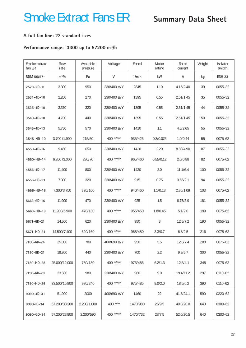
Summary Data SheetSmoke Extract Fans ER
Smoke extract Flow Available Voltage Speed Motor Rated Weight Isolatorfan ER rate pressure rating current switch
RDM 56/57- m³/h Pa V 1/min kW A kg ESH 23
2528-2D-11 3.300 950 230/400 ∆/Y 2845 1.10 4.15/2.40 39 0055-32
2531-4D-10 2.200 270 230/400 ∆/Y 1395 0.55 2.51/1.45 35 0055-32
3535-4D-10 3.370 320 230/400 ∆/Y 1395 0.55 2.51/1.45 44 0055-32
3540-4D-10 4.700 440 230/400 ∆/Y 1395 0.55 2.51/1.45 50 0055-32
3545-4D-13 5.750 570 230/400 ∆/Y 1410 1.1 4.6/2.65 55 0055-32
3545-HD-10 3.700 /1.900 215/50 400 Y/YY 935/425 0.3/0.075 1.0/0.44 55 0075-62
4550-4D-16 9.450 650 230/400 ∆/Y 1420 2.20 8.50/4.90 87 0055-32
4550-HD-14 6.200 /3.000 280/70 400 Y/YY 965/460 0.55/0.12 2.0/0.88 82 0075-62
4556-4D-17 11.400 800 230/400 ∆/Y 1420 3.0 11.1/6.4 100 0055-32
4556-6D-13 7.300 320 230/400 ∆/Y 915 0.75 3.65/2.1 94 0055-32
4556-HD-16 7.300/3.750 320/100 400 Y/YY 940/460 1.1/0.18 2.85/1.09 103 0075-62
5663-6D-16 11.900 470 230/400 ∆/Y 925 1.5 6.75/3.9 181 0055-32
5663-HD-19 11.900/5.900 470/130 400 Y/YY 955/450 1.8/0.45 5.1/2.0 199 0075-62
5671-6D-21 14.500 620 230/400 ∆/Y 950 3 12.5/7.2 190 0055-32
5671-HD-24 14.500/7.400 620/160 400 Y/YY 965/480 3.3/0.7 6.8/2.5 216 0075-62
7180-6D-24 25.000 780 400/690 ∆/Y 950 5.5 12.8/7.4 288 0075-62
7180-8D-21 18.800 440 230/400 ∆/Y 700 2.2 9.9/5.7 300 0055-32
7180-HD-28 25.000/12.000 780/180 400 Y/YY 975/485 6.2/1.3 12.5/4.1 348 0075-62
7190-6D-28 33.500 980 230/400 ∆/Y 960 9.0 19.4/11.2 297 0110-62
7190-HD-26 33.500/15.800 980/240 400 Y/YY 975/485 9.0/2.0 18.5/6.2 390 0110-62
9090-4D-31 51.900 2000 400/690 ∆/Y 1460 22 41.5/24.1 590 0220-62
9090-ID-34 57.200/38.200 2.200/1.000 400 Y/Y 1470/980 26/9.5 49.0/20.0 640 0300-62
9090-GD-34 57.200/28.800 2.200/590 400 Y/YY 1470/732 28/7.5 52.0/20.5 640 0300-62
A full fan line: 23 standard sizes
Performance range: 3300 up to 57200 m³/h
28
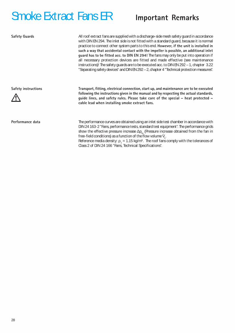
All roof extract fans are supplied with a discharge-side mesh safety guard in accordancewith DIN EN 294. The inlet side is not fitted with a standard guard, because it is normalpractice to connect other system parts to this end. However, if the unit is installed insuch a way that accidental contact with the impeller is possible, an additional inletguard has to be fitted acc. to DIN EN 294! The fans may only be put into operation ifall necessary protection devices are fitted and made effective (see maintenanceinstructions)! The safety guards are to be executed acc. to DIN EN 292 – 1, chapter 3.22”Separating safety devices“ and DIN EN 292 – 2, chapter 4 ”Technical protection measures“.
Transport, fitting, electrical connection, start up, and maintenance are to be executedfollowing the instructions given in the manual and by respecting the actual standards,guide lines, and safety rules. Please take care of the special � heat protected �cable lead when installing smoke extract fans.
The performance curves are obtained using an inlet side test chamber in accordance withDIN 24 163-2 ”Fans, performance tests, standard test equipment“. The performance gridsshow the effective pressure increase ∆pfa (Pressure increase obtained from the fan infree-field conditions) as a function of the flow volume VL.Reference media density: ρ1 = 1.15 kg/m³. The roof fans comply with the tolerances ofClass 2 of DIN 24 166 ”Fans, Technical Specifications“.
Smoke Extract Fans ER Important Remarks
Safety Guards
Safety instructions
Performance data
29
r
dB30
20
10
1 5
ab
m 10r
Smoke Extract Fans ER Important Remarks
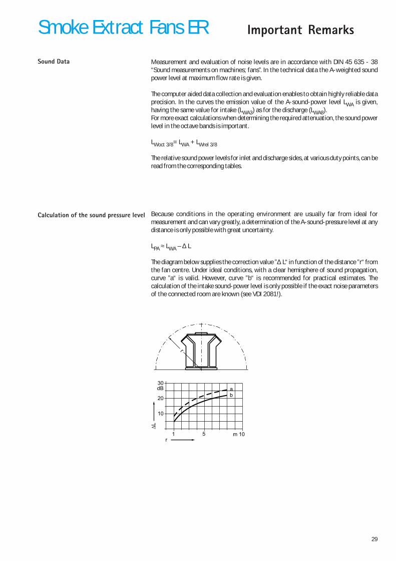
Measurement and evaluation of noise levels are in accordance with DIN 45 635 - 38“Sound measurements on machines; fans”. In the technical data the A-weighted soundpower level at maximum flow rate is given.
The computer aided data collection and evaluation enables to obtain highly reliable dataprecision. In the curves the emission value of the A-sound-power level LWA is given,having the same value for intake (LWA3) as for the discharge (LWA8).For more exact calculations when determining the required attenuation, the sound powerlevel in the octave bands is important.
LWoct 3/8= LWA + LWrel 3/8
The relative sound power levels for inlet and discharge sides, at various duty points, can beread from the corresponding tables.
Because conditions in the operating environment are usually far from ideal formeasurement and can vary greatly, a determination of the A-sound-pressure level at anydistance is only possible with great uncertainty.
LPA ≈ LWA – ∆ L
The diagram below supplies the correction value ”∆ L“ in function of the distance ”r“ fromthe fan centre. Under ideal conditions, with a clear hemisphere of sound propagation,curve ”a“ is valid. However, curve ”b“ is recommended for practical estimates. Thecalculation of the intake sound-power level is only possible if the exact noise parametersof the connected room are known (see VDI 2081!).
Calculation of the sound pressure level
Sound Data
30
Technical DataSmoke Extract Fans ER
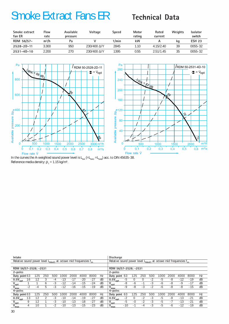
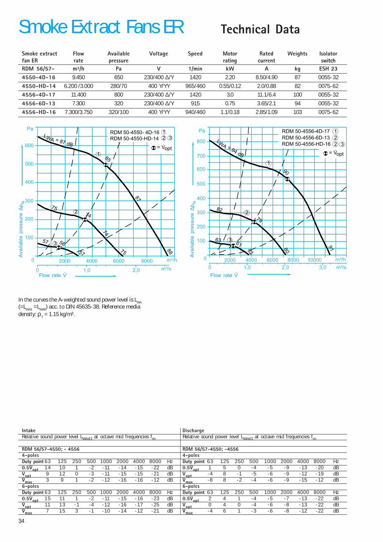
In the curves the A-weighted sound power level is LWA (=LWA3 =LWA8) acc. to DIN 45635-38.Reference media density: ρ1 = 1.15 kg/m³.
Smoke extract Flow Available Voltage Speed Motor Rated Weights Isolatorfan ER rate pressure rating current switchRDM 56/57- m³/h Pa V 1/min kW A kg ESH 232528-2D-11 3.300 950 230/400 ∆/Y 2845 1.10 4.15/2.40 39 0055-32
2531-4D-10 2.200 270 230/400 ∆/Y 1395 0.55 2.51/1.45 35 0055-32
Intake DischargeRelative sound power level LWrel3 at octave mid frequencies fm Relative sound power level LWrel3 at octave mid frequencies fm
RDM 56/57-2528; -2531 RDM 56/57-2528; -25312-poles 2-polesDuty point 63 125 250 500 1000 2000 4000 8000 Hz Duty point 63 125 250 500 1000 2000 4000 8000 Hz0.5Vopt 16 12 3 -4 -13 -17 -20 -27 dB 0.5Vopt -5 0 0 -2 -5 -8 -12 -19 dBVopt 1 1 6 -3 -12 -14 -15 -24 dB Vopt -8 -6 -1 -3 -6 -8 -9 -17 dBVmax -2 -4 5 -3 -12 -16 -15 -19 dB Vmax -9 -8 -3 -2 -6 -8 -8 -15 dB4-poles 4-polesDuty point 63 125 250 500 1000 2000 4000 8000 Hz Duty point 63 125 250 500 1000 2000 4000 8000 Hz0.5Vopt 13 12 2 -3 -10 -14 -19 -27 dB 0.5Vopt -2 0 -2 -3 -5 -8 -13 -21 dBVopt 9 12 1 -3 -10 -13 -18 -27 dB Vopt -5 -0 -2 -3 -5 -7 -13 -21 dBVmax 4 10 1 -2 -10 -13 -15 -23 dB Vmax -10 -1 -4 -3 -5 -6 -12 -19 dB
RDM 50-2528-2D-11Pa
800
600
400
200
0 500 1000 1500 2000 2500 3000 m³/h
m³/s0 0,1 0,2 0,3 0,4 0,5 0,6 0,7 0,8
87
86
88
LWA = 88 dB
= V·opt
RDM 50-2531-4D-10Pa
280
240
200
160
120
80
40
0 500
0 0,1 0,2 0,3 0,4 0,5 0,6
1000 1500 2000 m³/h
m³/s
LWA = 72 dB
= V·opt
Flow rate V
Ava
ilabl
e pr
essu
re ∆
p fa
Flow rate V
Ava
ilabl
e pr
essu
re ∆
p fa
31
DimensionsSmoke Extract Fans ER
440
559
440
32
600
ø 12
286
330
6xM6
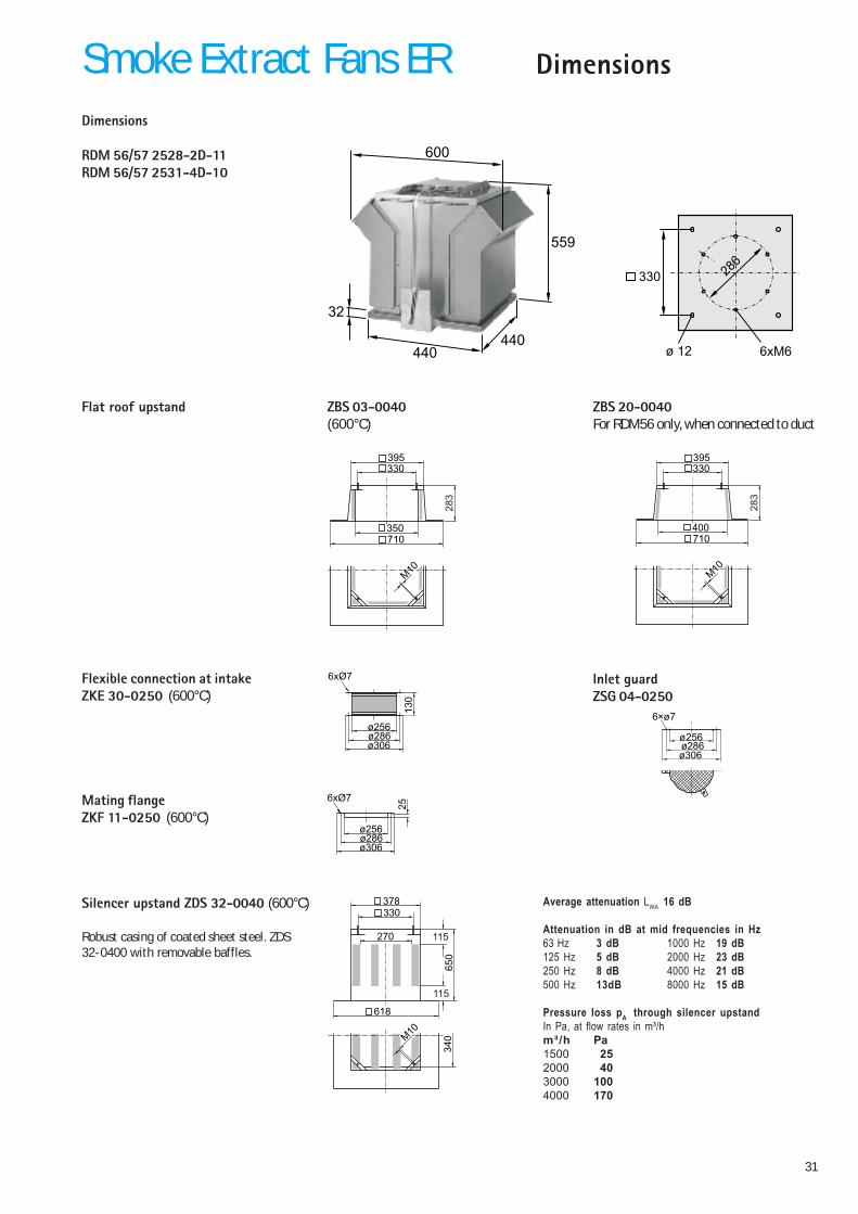
Dimensions
RDM 56/57 2528-2D-11RDM 56/57 2531-4D-10
Flexible connection at intakeZKE 30-0250 (600°C)
6xØ7
ø286ø306
ø256
130
ZBS 20-0040For RDM56 only, when connected to duct
Flat roof upstand ZBS 03-0040(600°C)
350
330395
M10
710
283
400
330395
M10
710
28
3
Mating flangeZKF 11-0250 (600°C)
6xØ7
ø286ø306
ø256
25
Average attenuation LWA 16 dB
Attenuation in dB at mid frequencies in Hz63 Hz 3 dB 1000 Hz 19 dB125 Hz 5 dB 2000 Hz 23 dB250 Hz 8 dB 4000 Hz 21 dB500 Hz 13dB 8000 Hz 15 dB
Pressure loss pA through silencer upstandIn Pa, at flow rates in m³/hm³/h Pa1500 252000 403000 1004000 170
Silencer upstand ZDS 32-0040 (600°C)
Robust casing of coated sheet steel. ZDS32-0400 with removable baffles.
618
378330
270
65
0340
115
115
M10
Inlet guardZSG 04-0250
6×ø7
ø286ø306
ø256
32
Technical DataSmoke Extract Fans ER
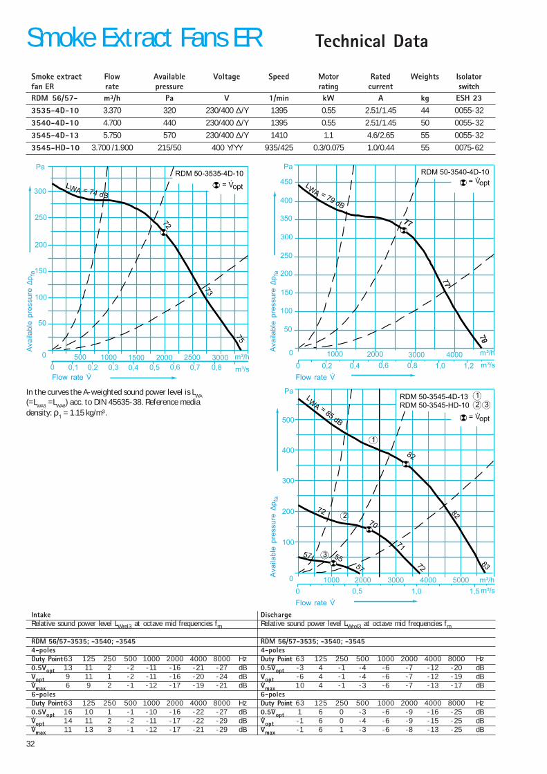
In the curves the A-weighted sound power level is LWA
(=LWA3 =LWA8) acc. to DIN 45635-38. Reference mediadensity: ρ1 = 1.15 kg/m³.
Intake DischargeRelative sound power level LWrel3 at octave mid frequencies fm Relative sound power level LWrel3 at octave mid frequencies fm
RDM 56/57-3535; -3540; -3545 RDM 56/57-3535; -3540; -35454-poles 4-polesDuty Point63 125 250 500 1000 2000 4000 8000 Hz Duty Point 63 125 250 500 1000 2000 4000 8000 Hz0.5Vopt 13 11 2 -2 -11 -16 -21 -27 dB 0.5Vopt -3 4 -1 -4 -6 -7 -12 -20 dBVopt 9 11 1 -2 -11 -16 -20 -24 dB Vopt -6 4 -1 -4 -6 -7 -12 -19 dBVmax 6 9 2 -1 -12 -17 -19 -21 dB Vmax 10 4 -1 -3 -6 -7 -13 -17 dB6-poles 6-polesDuty Point63 125 250 500 1000 2000 4000 8000 Hz Duty Point 63 125 250 500 1000 2000 4000 8000 Hz0.5Vopt 16 10 1 -1 -10 -16 -22 -27 dB 0.5Vopt 1 6 0 -3 -6 -9 -16 -25 dBVopt 14 11 2 -2 -11 -17 -22 -29 dB Vopt -1 6 0 -4 -6 -9 -15 -25 dBVmax 11 13 3 -1 -12 -17 -21 -29 dB Vmax -1 6 1 -3 -6 -8 -13 -25 dB
Smoke extract Flow Available Voltage Speed Motor Rated Weights Isolatorfan ER rate pressure rating current switchRDM 56/57- m³/h Pa V 1/min kW A kg ESH 233535-4D-10 3.370 320 230/400 ∆/Y 1395 0.55 2.51/1.45 44 0055-32
3540-4D-10 4.700 440 230/400 ∆/Y 1395 0.55 2.51/1.45 50 0055-32
3545-4D-13 5.750 570 230/400 ∆/Y 1410 1.1 4.6/2.65 55 0055-32
3545-HD-10 3.700 /1.900 215/50 400 Y/YY 935/425 0.3/0.075 1.0/0.44 55 0075-62
RDM 50-3535-4D-10Pa
300
250
200
150
100
50
0 500 1000 1500 2000 2500 3000
m³/s
m³/h
0 0,1 0,2 0,3 0,4 0,5 0,6 0,7 0,8
72
73
75
LWA = 74 dB
= V·opt
m³/s0 0,2 0,4 0,6 0,8 1,0 1,2
0 1000 2000 3000 4000 m³/h
50
100
150
200
250
300
350
400
450
PaRDM 50-3540-4D-10
LWA = 79 dB
= V·opt
0 1000 2000 3000 4000 5000 m³/h
RDM 50-3545-4D-13RDM 50-3545-HD-10
Pa
500
400
300
200
100
m³/s0 1,51,00,5
82
82
83
LW
A =85
dB= V·opt
32
1
1
2
3
72
70
71
72
Flow rate V
Ava
ilabl
e pr
essu
re ∆
p fa
Flow rate V
Ava
ilabl
e pr
essu
re ∆
p fa
Flow rate V
Ava
ilabl
e pr
essu
re ∆
p fa

33
600
709
600
32
770
ø 12
395
450
8xM8
Dimensions
RDM 56/57 3535-4D-10RDM 56/57 3540-4D-10RDM 56/57 3545-4D-13RDM 56/57 3540-HD-10
DimensionsSmoke Extract Fans ER
Flexible connection at intakeZKE 30-0355 (600°C)
Mating flangeZKF 11-0355 (600°C)
Silencer upstand ZDS 32-0056(600°C)with removable baffles
Flat roof upstand
510
450555
M10
870
28
3
560
450555
M10
870
28
3
ZBS 20-0056For RDM56 only, when connected to duct
ZBS 03-0056(600°C)
8xØ9,5
ø395ø421
ø361
130
8xØ9,5
ø395ø421
ø361
30
Average attenuation LWA 16 dB
Attenuation in dB at mid frequencies in Hz63 Hz 3 dB 1000 Hz 18 dB125 Hz 5 dB 2000 Hz 21 dB250 Hz 8 dB 4000 Hz 20 dB500 Hz 12dB 8000 Hz 15 dB
Pressure loss pA through silencer upstandIn Pa, at flow rates in m³/hm³/h Pa3000 254000 426000 808000 160
778
538450
430
80
0500
115
115
M10
Inlet guardZSG 04-0355
8×ø9.5
ø395ø421
ø361
34
Technical DataSmoke Extract Fans ER
Intake DischargeRelative sound power level LWrel3 at octave mid frequencies fm Relative sound power level LWrel3 at octave mid frequencies fm
RDM 56/57-4550; - 4556 RDM 56/57-4550; -45564-poles 4-polesDuty point 63 125 250 500 1000 2000 4000 8000 Hz Duty point 63 125 250 500 1000 2000 4000 8000 Hz0.5Vopt 14 10 1 -2 -11 -14 -15 -22 dB 0.5Vopt 1 5 0 -4 -5 -9 -13 -20 dBVopt 9 12 0 -3 -11 -15 -15 -21 dB Vopt -4 8 -1 -5 -6 -9 -12 -19 dBVmax 3 9 1 -2 -12 -16 -16 -12 dB Vmax -8 8 -2 -4 -6 -9 -15 -12 dB6-poles 6-polesDuty point 63 125 250 500 1000 2000 4000 8000 Hz Duty point 63 125 250 500 1000 2000 4000 8000 Hz0.5Vopt 15 11 1 -2 -11 -15 -16 -23 dB 0.5Vopt 2 4 1 -4 -5 -7 -13 -22 dBVopt 11 13 -1 -4 -12 -16 -17 -25 dB Vopt 0 4 0 -4 -6 -8 -13 -22 dBVmax 7 15 3 -1 -10 -14 -12 -21 dB Vmax -4 6 1 -3 -6 -8 -12 -22 dB
Smoke extract Flow Available Voltage Speed Motor Rated Weights Isolatorfan ER rate pressure rating current switchRDM 56/57- m³/h Pa V 1/min kW A kg ESH 234550-4D-16 9.450 650 230/400 ∆/Y 1420 2.20 8.50/4.90 87 0055-32
4550-HD-14 6.200 /3.000 280/70 400 Y/YY 965/460 0.55/0.12 2.0/0.88 82 0075-62
4556-4D-17 11.400 800 230/400 ∆/Y 1420 3.0 11.1/6.4 100 0055-32
4556-6D-13 7.300 320 230/400 ∆/Y 915 0.75 3.65/2.1 94 0055-32
4556-HD-16 7.300/3.750 320/100 400 Y/YY 940/460 1.1/0.18 2.85/1.09 103 0075-62
Pa
600
500
400
300
200
100
0 2000 4000 6000 8000 m³/h
0 1,0 2,0 m³/s
RDM 50-4550- 4D-16RDM 50-4550-HD-14
87
88
85
LWA = 87 dB= V·opt
12 3
7557
57 56
74
74
75
1
2
3
RDM 50-4556-4D-17
RDM 50-4556-6D-13
RDM 50-4556-HD-16
Pa
800
700
600
500
400
300
200
100
0
3,02,01,00
2000 4000 6000 8000 10000 m³/h
m³/s
90
91
LWA = 94 dB = V·opt
1
2
32
80
79
82
62
63 61
1
2
3
Flow rate V
Ava
ilabl
e pr
essu
re ∆
p fa
Flow rate V
Ava
ilabl
e pr
essu
re ∆
p fa
In the curves the A-weighted sound power level is LWA
(=LWA3 =LWA8) acc. to DIN 45635-38. Reference mediadensity: ρ1 = 1.15 kg/m³.
35
750
794
750
32
985
ø 14
487
590
6xM8
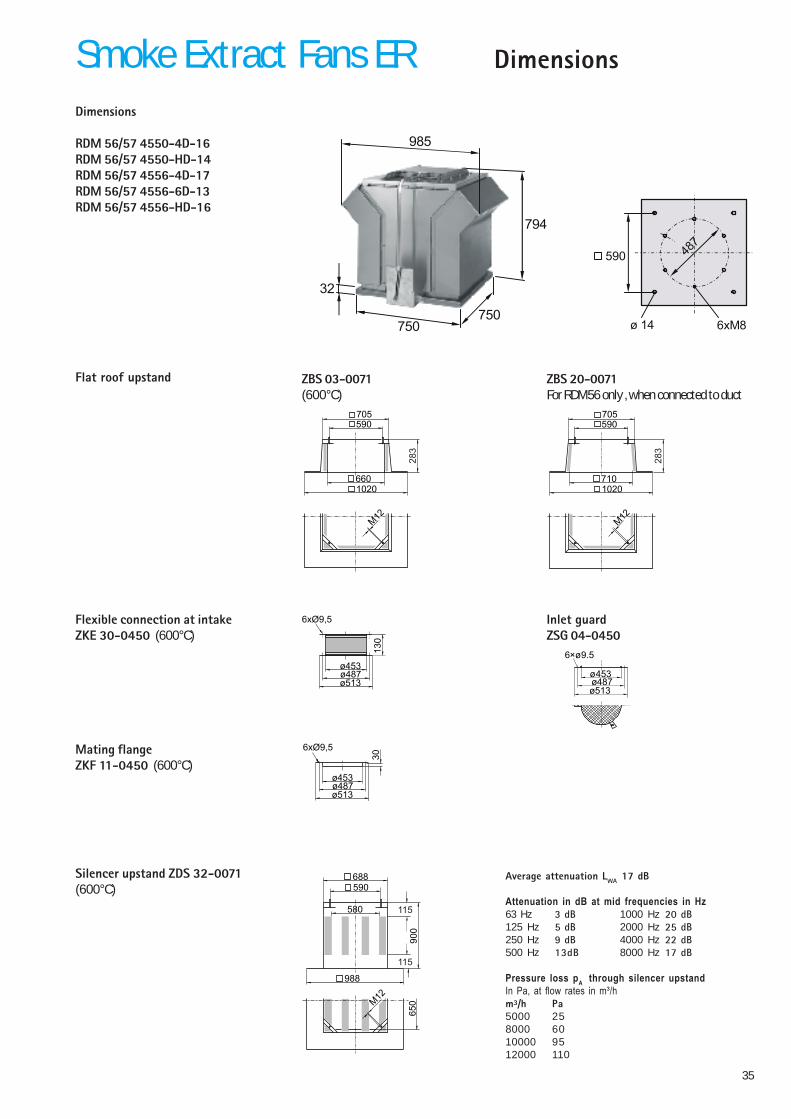
DimensionsSmoke Extract Fans ERDimensions
RDM 56/57 4550-4D-16RDM 56/57 4550-HD-14RDM 56/57 4556-4D-17RDM 56/57 4556-6D-13RDM 56/57 4556-HD-16
Flat roof upstand
Flexible connection at intakeZKE 30-0450 (600°C)
Mating flangeZKF 11-0450 (600°C)
Silencer upstand ZDS 32-0071(600°C)
Average attenuation LWA 17 dB
Attenuation in dB at mid frequencies in Hz63 Hz 3 dB 1000 Hz 20 dB125 Hz 5 dB 2000 Hz 25 dB250 Hz 9 dB 4000 Hz 22 dB500 Hz 13dB 8000 Hz 17 dB
Pressure loss pA through silencer upstandIn Pa, at flow rates in m³/hm³/h Pa5000 258000 6010000 9512000 110
988
688590
580
90
06
50M
12
115
115
ø487ø513
ø453
30
6xØ9,5
ø487ø513
ø453
13
0
6xØ9,5
ZBS 20-0071For RDM56 only , when connected to duct
ZBS 03-0071(600°C)
660
590705
M12
1020
28
3
710
590705
M12
1020
28
3
Inlet guardZSG 04-0450
6×ø9.5
ø487ø513
ø453
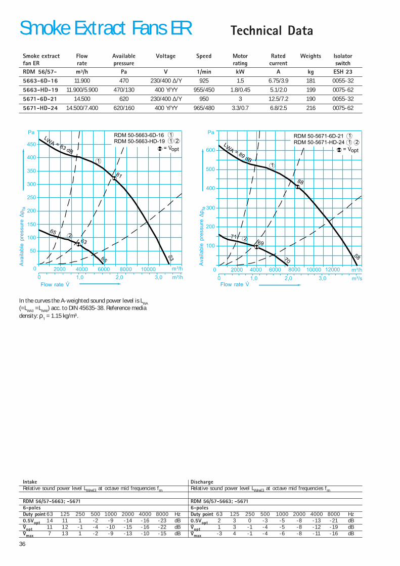
36
Technical DataSmoke Extract Fans ER
In the curves the A-weighted sound power level is LWA
(=LWA3 =LWA8) acc. to DIN 45635-38. Reference mediadensity: ρ1 = 1.15 kg/m³.
Intake DischargeRelative sound power level LWrel3 at octave mid frequencies fm Relative sound power level LWrel3 at octave mid frequencies fm
RDM 56/57-5663; -5671 RDM 56/57-5663; -56716-poles 6-polesDuty point 63 125 250 500 1000 2000 4000 8000 Hz Duty point 63 125 250 500 1000 2000 4000 8000 Hz0.5Vopt 14 11 1 -2 -9 -14 -16 -23 dB 0.5Vopt 2 3 0 -3 -5 -8 -13 -21 dBVopt 11 12 -1 -4 -10 -15 -16 -22 dB Vopt 1 3 -1 -4 -5 -8 -12 -19 dBVmax 7 13 1 -2 -9 -13 -10 -15 dB Vmax -3 4 -1 -4 -6 -8 -11 -16 dB
Smoke extract Flow Available Voltage Speed Motor Rated Weights Isolatorfan ER rate pressure rating current switchRDM 56/57- m³/h Pa V 1/min kW A kg ESH 235663-6D-16 11.900 470 230/400 ∆/Y 925 1.5 6.75/3.9 181 0055-32
5663-HD-19 11.900/5.900 470/130 400 Y/YY 955/450 1.8/0.45 5.1/2.0 199 0075-62
5671-6D-21 14.500 620 230/400 ∆/Y 950 3 12.5/7.2 190 0055-32
5671-HD-24 14.500/7.400 620/160 400 Y/YY 965/480 3.3/0.7 6.8/2.5 216 0075-62
2
1
1
63
65
65
81
83
RDM 50-5663-6D-16RDM 50-5663-HD-19
Pa
450
400
350
300
250
200
150
100
50
0
0 1,0 2,0 3,0
2000 4000 6000 8000 10000 m³/h
m³/h
LWA = 83 dB= V·opt
21
69
70
71
88
88
2
1
1
RDM 50-5671-6D-21RDM 50-5671-HD-24
Pa
600
500
400
300
200
100
0
0 1,0 2,0 3,0
2000 4000 6000 8000 10000 12000 m³/h
m³/s
LWA = 89 dB
= V·opt
21
Flow rate V
Ava
ilabl
e pr
essu
re ∆
p fa
Flow rate V
Ava
ilabl
e pr
essu
re ∆
p fa
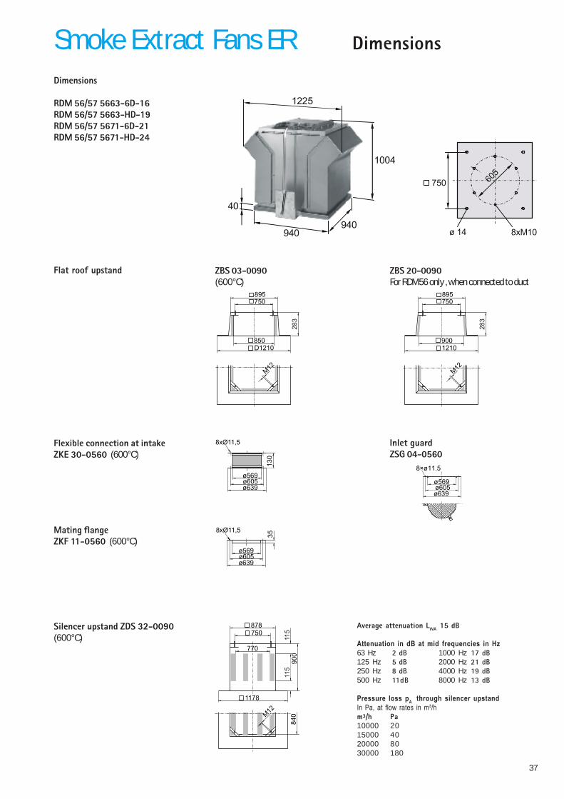
37
DimensionsSmoke Extract Fans ERDimensions
RDM 56/57 5663-6D-16RDM 56/57 5663-HD-19RDM 56/57 5671-6D-21RDM 56/57 5671-HD-24
Flat roof upstand
Flexible connection at intakeZKE 30-0560 (600°C)
Mating flangeZKF 11-0560 (600°C)
940
1004
940
40
1225
ø 14
605
750
8xM10
Silencer upstand ZDS 32-0090(600°C)
Average attenuation LWA 15 dB
Attenuation in dB at mid frequencies in Hz63 Hz 2 dB 1000 Hz 17 dB125 Hz 5 dB 2000 Hz 21 dB250 Hz 8 dB 4000 Hz 19 dB500 Hz 11dB 8000 Hz 13 dB
Pressure loss pA through silencer upstandIn Pa, at flow rates in m³/hm³/h Pa10000 2015000 4020000 8030000 180
1178
878750
770
90
08
40
11
511
5
M12
ø605ø639
ø569
358xØ11,5
ø605ø639
ø569
13
0
8xØ11,5
850
750895
M12
D1210
28
3
900
750895
M12
1210
28
3
ZBS 20-0090For RDM56 only , when connected to duct
ZBS 03-0090(600°C)
Inlet guardZSG 04-0560
8×ø11.5
ø605ø639
ø569

38
Technical DataSmoke Extract Fans ER
In the curves the A-weighted sound power level is LWA
(=LWA3 =LWA8) acc. to DIN 45635-38. Reference mediadensity: ρ1 = 1.15 kg/m³.
Intake DischargeRelative sound power level LWrel3 at octave mid frequencies fm Relative sound power level LWrel3 at octave mid frequencies fm
RDM 56/57-7180; -7190 RDM 56/57-7180; -71906-poles 6-polesDuty point 63 125 250 500 1000 2000 4000 8000 Hz Duty point 63 125 250 500 1000 2000 4000 8000 Hz0.5Vopt 15 11 1 -2 -10 -14 -16 -23 dB 0.5Vopt 2 4 1 -4 -5 -8 -13 -21 dBVopt 11 13 -1 -4 -11 -15 -17 -23 dB Vopt 1 4 0 -4 -6 -8 -13 -21 dBVmax 7 14 3 -1 -10 -13 -12 -19 dB Vmax -3 4 0 -3 -6 -8 -12 -20 dB8-poles 8-polesDuty point 63 125 250 500 1000 2000 4000 8000 Hz Duty point 63 125 250 500 1000 2000 4000 8000 Hz0.5Vopt 15 5 1 -2 -8 -14 -17 -24 dB 0.5Vopt 3 1 -1 -3 -6 -8 -15 -23 dBVopt 15 4 0 -3 -7 -13 -15 -24 dB Vopt 3 0 -2 -3 -5 -8 -14 -23 dBVmax 15 3 1 -3 -9 -14 -13 -25 dB Vmax 3 2 0 -3 -6 -9 -10 -23 dB
Smoke extract Flow Available Voltage Speed Motor Rated Weights Isolatorfan ER rate pressure rating current switchRDM 56/57- m³/h Pa V 1/min kW A kg ESH 237180-6D-24 25.000 780 400/690 ∆/Y 950 5.5 12.8/7.4 288 0075-62
7180-8D-21 18.800 440 230/400 ∆/Y 700 2.2 9.9/5.7 300 0055-32
7180-HD-28 25.000/12.000 780/180 400 Y/YY 975/485 6.2/1.3 12.5/4.1 348 0075-62
7190-6D-28 33.500 980 230/400 ∆/Y 960 9.0 19.4/11.2 297 0110-62
7190-HD-26 33.500/15.800 980/240 400 Y/YY 975/485 9.0/2.0 18.5/6.2 390 0110-62
RDM 50-7180-6D-24RDM 50-7180-8D-21RDM 50-7180-HD-28
Pa
800
700
600
500
400
300
200
100
0
0 1 2 3 4 5 6 7
5000 10000 15000 20000 25000 m³/h
m³/s
LWA = 92 dB
89
90
91
= V·opt
84
83
84
82
12
31
73
72
70
1
2
3
93
93
94
RDM 50-7190-6D-28RDM 50-7190-HD-26
Pa
900
800
700
600
500
400
300
200
100
0
0 1 2 3 4 5 6 7 8 9
5000 10000 15000 20000 25000 30000 m³/h
m³/s
LWA = 94 dB = V·opt
121
75
77
77
1
2
Flow rate V
Ava
ilabl
e pr
essu
re ∆
p fa
Flow rate V
Ava
ilabl
e pr
essu
re ∆
p fa

39
DimensionsSmoke Extract Fans ERDimensions
RDM 56/57 7180-6D-24RDM 56/57 7180-8D-21RDM 56/57 7180-HD-28RDM 56/57 7190-6D-28RDM 56/57 7190-HD-26
Flat roof upstand
Flexible connection at intakeZKE 30-0710 (600°C)
Mating flangeZKF 11-0710 (600°C)
1270
1304
1270
65
1625
ø 14
751
1050
8xM10
Silencer upstand ZDS 32-0125(600°C)
Average attenuation LWA 16 dB
Attenuation in dB at mid frequencies in Hz63 Hz 3 dB 1000 Hz 20 dB125 Hz 6 dB 2000 Hz 25 dB250 Hz 8 dB 4000 Hz 23 dB500 Hz 14dB 8000 Hz 11 dB
Pressure loss pA through silencer upstandIn Pa, at flow rates in m³/hm³/h Pa17000 2020000 3025000 4030000 6540000 110
1526
12261050
1117
90
011
90
11
511
5
M12
ø751ø785
ø715
358xØ11,5
ø751ø785
ø715
13
0
8xØ11,5
ZBS 20-0125For RDM56 only , when connected to duct
ZBS 03-0125(600°C)
1160
10501205
M12
1520
28
3
1210
10501205
M12
1520
28
3
Inlet guardZSG 04-0710
8×ø11.5
ø751ø785
ø715

40
Technical DataSmoke Extract Fans ER
In the curves the A-weighted sound power level is LWA
(=LWA3 =LWA8) acc. to DIN 45635-38. Reference mediadensity: ρ1 = 1.15 kg/m³.
Intake DischargeRelative sound power level LWrel3 at octave mid frequencies fm Relative sound power level LWrel3 at octave mid frequencies fm
RDM 56/57-9090 RDM 56/57-90904-poles 4-polesDuty point 63 125 250 500 1000 2000 4000 8000 Hz Duty point 63 125 250 500 1000 2000 4000 8000 Hz0.5Vopt 15 11 1 -2 -10 -14 -16 -23 dB 0.5Vopt 2 4 1 -4 -5 -8 -13 -21 dBVopt 11 13 -1 -4 -11 -15 -17 -23 dB Vopt 1 4 0 -4 -6 -8 -13 -21 dBVmax 7 14 3 -1 -10 -13 -12 -19 dB Vmax -3 4 0 -3 -6 -8 -12 -20 dB6-poles 6-polesDuty point 63 125 250 500 1000 2000 4000 8000 Hz Duty point 63 125 250 500 1000 2000 4000 8000 Hz0.5Vopt 15 11 1 -2 -10 -14 -16 -23 dB 0.5Vopt 2 4 1 -4 -5 -8 -13 -21 dBVopt 11 13 -1 -4 -11 -15 -17 -23 dB Vopt 1 4 0 -4 -6 -8 -13 -21 dBVmax 7 14 3 -1 -10 -13 -12 -19 dB Vmax -3 4 0 -3 -6 -8 -12 -20 dB
Smoke extract Flow Available Voltage Speed Motor Rated Weights Isolatorfan ER rate pressure rating current switchRDM 56/57- m³/h Pa V 1/min kW A kg ESH 239090-4D-31 51.900 2000 400/690 ∆/Y 1460 22 41.5/24.1 590 0220-62
9090-ID-34 57.200/38.200 2.200/1.000 400 Y/Y 1470/980 26/9.5 49.0/20.0 640 0300-62
9090-GD-34 57.200/28.800 2.200/590 400 Y/YY 1470/732 28/7.5 52.0/20.5 640 0300-62
RDM 50-9090-4D-31RDM 50-9090-ID-34RDM 50-9090-GD-34
Pa
109
111
110
1800
1600
1400
1200
1000
800
600
400
200
0
0 2,5 5 7,5 10 12,5
10000 20000 30000 40000 50000 m³/h
m³/s
LWA = 111 dB
2000
2
1
2
101
99
100
101
2200
= V·opt
3
94
93
9294
31
41
107
109
108
109
4
Flow rate V
Ava
ilabl
e pr
essu
re ∆
p fa
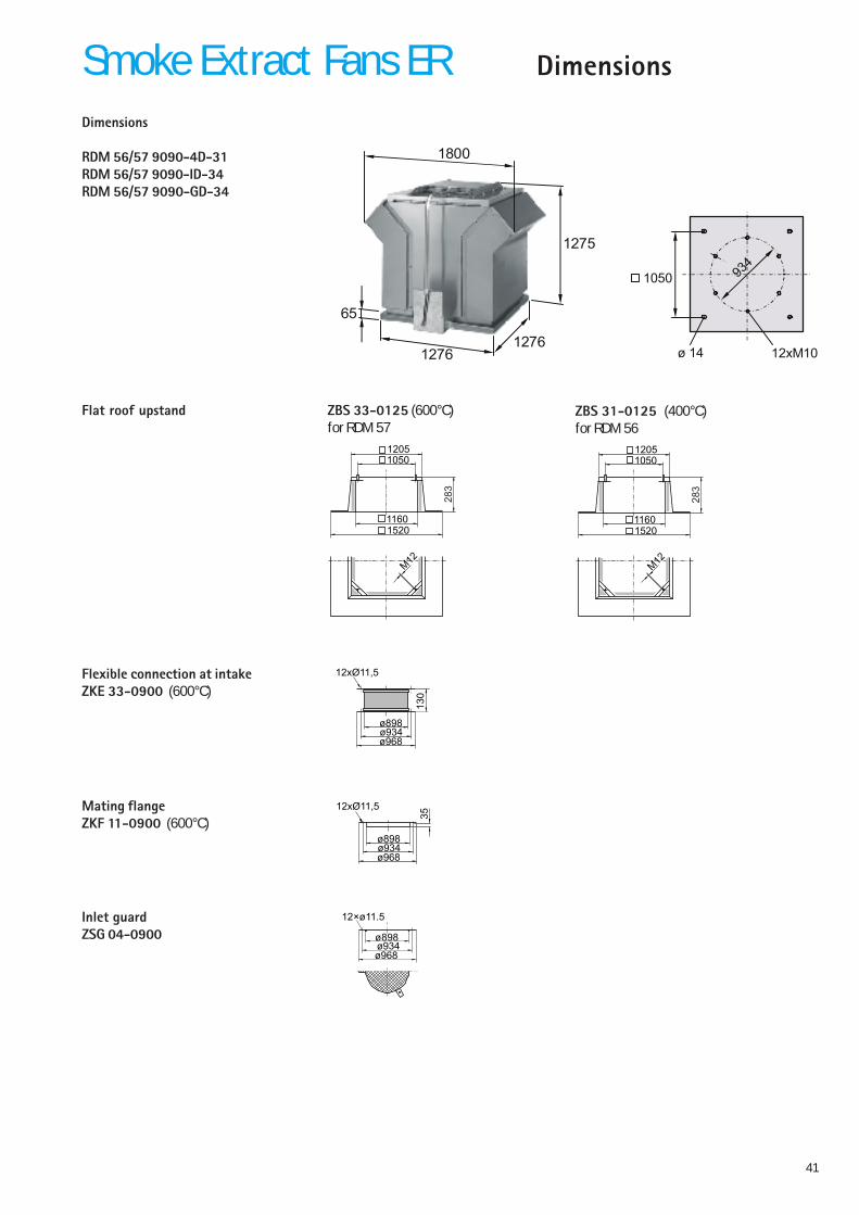
41
DimensionsSmoke Extract Fans ERDimensions
RDM 56/57 9090-4D-31RDM 56/57 9090-ID-34RDM 56/57 9090-GD-34
Flat roof upstand
Flexible connection at intakeZKE 33-0900 (600°C)
Mating flangeZKF 11-0900 (600°C)
1276
1275
1276
65
1800
ø 14
934
1050
12xM10
ø934ø968
ø898
3512xØ11,5
ø934ø968
ø898
13
0
12xØ11,5
1160
10501205
M12
1520
28
3
ZBS 33-0125 (600°C)for RDM 57
Inlet guardZSG 04-0900
12×ø11.5
ø934ø968
ø898
1160
10501205
M12
1520
28
3
ZBS 31-0125 (400°C)for RDM 56
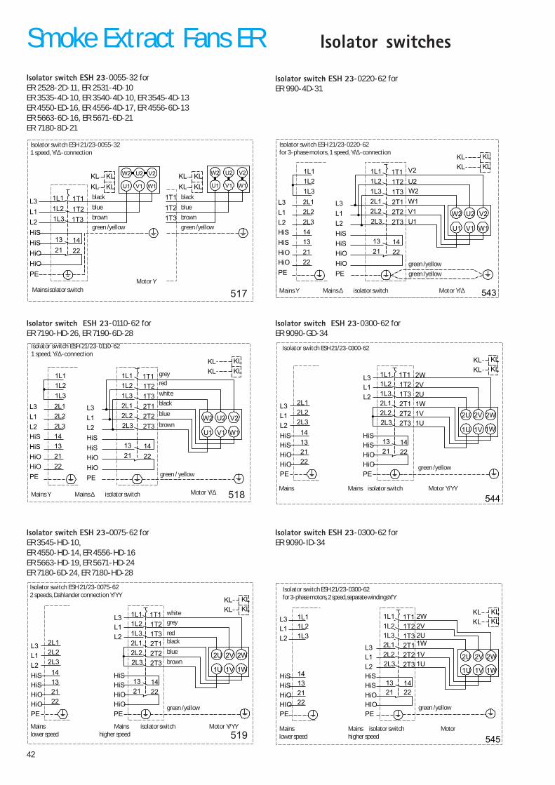
42
Isolator switch ESH 23-0055-32 forER 2528-2D-11, ER 2531-4D-10ER 3535-4D-10, ER 3540-4D-10, ER 3545-4D-13ER 4550-ED-16, ER 4556-4D-17, ER 4556-6D-13ER 5663-6D-16, ER 5671-6D-21ER 7180-8D-21
1T11L1
1T31L3
2T12L1
2T22L2
2T32L3
1T21L2
1413
2221
L2
L3
L1
22
21
13
14
2L3
2L2
2L1
HiS
HiO
HiO
HiS
PE
L2
L3
L1
PE
HiS
HiO
HiO
HiS
KL
KL
KL
KL
2U 2V 2W
1U 1V 1W
519
Isolator switch ESH 21/23-0075-622 speeds, Dahlander connection Y/YY
Mains isolator switch Motor Y/YYMainslower speed higher speed
black
blue
brown
green /yellow
red
greywhite
Isolator switch ESH 23-0110-62 forER 7190-HD-26, ER 7190-6D-28
Isolator switchesSmoke Extract Fans ER
KL
KL
KL
KL
1T3
1T2
1T11T11L1
1T31L3
1413
2221
1T21L2
L2
L3
HiS
HiO
HiO
HiS
L1
PE
W2 U2 V2
U1 V1 W1 KL
KL
KL
KLW2 U2 V2
U1 V1 W1
517
Isolator switch ESH 21/23-0055-321 speed, Y/∆-connection
black
blue
brown
green /yellow
black
blue
brown
green /yellow
Mains isolator switchMotor Y
L3
L1
L2
PE
HiO
HiO
HiS
HiS
1L3
1L2
1L1KL
KL
KL
KL
1T11L1
1T31L3
2T12L1
2T22L2
2T32L3
1T21L2
1413
2221
22
21
13
14
2L3
2L2
2L1
L2
L3
L1
PE
HiS
HiO
HiO
HiS
W2 U2 V2
U1 V1 W1
518
Isolator switch ESH 21/23-0110-621 speed, Y/∆-connection
black
brown
white
redgrey
blue
green / yellow
Motor Y/∆Mains Y Mains ∆ isolator switch
Isolator switch ESH 23-0075-62 forER 3545-HD-10,ER 4550-HD-14, ER 4556-HD-16ER 5663-HD-19, ER 5671-HD-24ER 7180-6D-24, ER 7180-HD-28
Isolator switch ESH 23-0220-62 forER 990-4D-31
543
W2
V2
U2
W1
V1
U1
L3
L1
L2
PE
HiO
HiO
HiS
HiS
1L3
1L2
1L1KL
KL
KL
KL
1T11L1
1T31L3
2T12L1
2T22L2
2T32L3
1T21L2
1413
2221
22
21
13
14
2L3
2L2
2L1
L2
L3
L1
PE
HiS
HiO
HiO
HiS
W2 U2 V2
U1 V1 W1
Isolator switch ESH 21/23-0220-62for 3-phase motors, 1 speed, Y/∆-connection
green /yellow
Motor Y/∆Mains Y Mains ∆ isolator switch
green /yellow
545
2W
1W
2V
2U
1V
1U
1T11L1
1T31L3
2T12L1
2T22L2
2T32L3
1T21L2
1413
2221
1L3
1L2
1L1
L2
L3
L1
L2
L3
L1
22
21
13
14
HiS
HiO
HIO
HiS
PEPE
HiS
HIO
HiO
HiS
KL
KL
KL
KL
2U 2V 2W
1U 1V 1W
Isolator switch ESH 21/23-0300-62for 3-phase motors, 2 speed, separate windingsY/Y
Mains Mains isolator switch Motorlower speed higher speed
green /yellow
544
2W
2V
2U
1W
1V
1U
1T11L1
1T31L3
2T12L1
2T22L2
2T32L3
1T21L2
1413
2221
L2
L3
L1
22
21
13
14
2L3
2L2
2L1
HiS
HiO
HiO
HiS
PE
L2
L3
L1
PE
HiS
HiO
HiO
HiS
KL
KL
KL
KL
2U 2V 2W
1U 1V 1W
Isolator switch ESH 21/23-0300-62
Mains Mains isolator switch Motor Y/YY
green /yellow
Isolator switch ESH 23-0300-62 forER 9090-GD-34
Isolator switch ESH 23-0300-62 forER 9090-ID-34
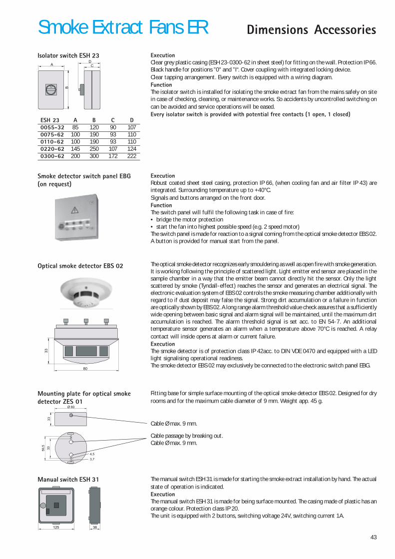
43
Dimensions AccessoriesSmoke Extract Fans ERIsolator switch ESH 23
Optical smoke detector EBS 02
ExecutionClear grey plastic casing (ESH 23-0300-62 in sheet steel) for fitting on the wall. Protection IP 66.Black handle for positions ”0" and ”I“. Cover coupling with integrated locking device.Clear tapping arrangement. Every switch is equipped with a wiring diagram.FunctionThe isolator switch is installed for isolating the smoke extract fan from the mains safely on sitein case of checking, cleaning, or maintenance works. So accidents by uncontrolled switching oncan be avoided and service operations will be eased.Every isolator switch is provided with potential free contacts (1 open, 1 closed)
The optical smoke detector recognizes early smouldering as well as open fire with smoke generation.It is working following the principle of scattered light. Light emitter end sensor are placed in thesample chamber in a way that the emitter beam cannot directly hit the sensor. Only the lightscattered by smoke (Tyndall-effect) reaches the sensor and generates an electrical signal. Theelectronic evaluation system of EBS 02 controls the smoke measuring chamber additionally withregard to if dust deposit may false the signal. Strong dirt accumulation or a failure in functionare optically shown by EBS 02. A long range alarm threshold value check assures that a sufficientlywide opening between basic signal and alarm signal will be maintained, until the maximum dirtaccumulation is reached. The alarm threshold signal is set acc. to EN 54-7. An additionaltemperature sensor generates an alarm when a temperature above 70°C is reached. A relaycontact will inside opens at alarm or current failure.ExecutionThe smoke detector is of protection class IP 42acc. to DIN VDE 0470 and equipped with a LEDlight signalising operational readiness.The smoke detector EBS 02 may exclusively be connected to the electronic switch panel EBG.
CD
AB
ESH 23 A B C D0055-32 85 120 90 1070075-62 100 190 93 1100110-62 100 190 93 1100220-62 145 250 107 1240300-62 200 300 172 222
Manual switch ESH 31 The manual switch ESH 31 is made for starting the smoke extract installation by hand. The actualstate of operation is indicated.ExecutionThe manual switch ESH 31 is made for being surface mounted. The casing made of plastic has anorange colour. Protection class IP 20.The unit is equipped with 2 buttons, switching voltage 24V, switching current 1A.
125 38
Mounting plate for optical smokedetector ZES 01
Fitting base for simple surface mounting of the optical smoke detector EBS 02. Designed for dryrooms and for the maximum cable diameter of 9 mm. Weight app. 45 g.
Cable Ø max. 9 mm.
333359
,5
Ø 80
4,53,7
Cable passage by breaking out.Cable Ø max. 9 mm.
80
33
Smoke detector switch panel EBG(on request)
ExecutionRobust coated sheet steel casing, protection IP 66, (when cooling fan and air filter IP 43) areintegrated. Surrounding temperature up to +40°C.Signals and buttons arranged on the front door.FunctionThe switch panel will fulfil the following task in case of fire:• bridge the motor protection• start the fan into highest possible speed (e.g. 2 speed motor)The switch panel is made for reaction to a signal coming from the optical smoke detector EBS 02.A button is provided for manual start from the panel.
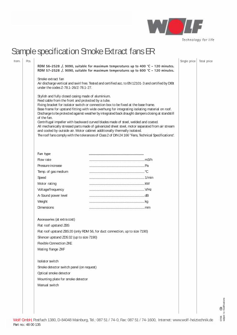
44
Sample specification Smoke Extract fans ERItem. Pcs. Total priceSingle price
RDM 56-2528 ./. 9090, suitable for maximum temperatures up to 400 °C - 120 minutes.RDM 57-2528 ./. 9090, suitable for maximum temperatures up to 600 °C - 120 minutes.
Smoke extract fanAir discharge vertical and swirl free. Tested and certified acc. to EN 12101-3 and certified by DIBtunder the codes Z-78.1-26/Z-78.1-27.
Stylish and fully closed casing made of aluminium.Feed cable from the front and protected by a tube.Fixing bracket for isolator switch or connection box to be fixed at the base frame.Base frame for upstand fitting with wide overhung for integrating isolating material on roof.Discharge to be protected against weather by integrated back draught dampers closing at standstillof the fan.Centrifugal impeller with backward curved blades made of steel, welded and coated.All mechanically stressed parts made of galvanized sheet steel, motor separated from air streamand cooled by outside air. Motor cabinet additionally thermally isolated.The roof fans comply with the tolerances of Class 2 of DIN 24 166 ”Fans, Technical Specifications“.
Fan type ................................................................
Flow rate ...........................................................................m3/h
Pressure increase ........................................................................... Pa
Temp. of gas medium ........................................................................... °C
Speed ........................................................................... 1/min
Motor rating ........................................................................... kW
Voltage/frequency ........................................................................... V/Hz
A-Sound power level ........................................................................... dB
Weight ........................................................................... kg
Dimensions ...........................................................................mm
Accessories (at extra cost)
Flat roof upstand ZBS
Flat roof upstand ZBS 20 (only RDM 56, for duct connection, up to size 7190)
Silencer upstand ZDS 32 (up to size 7190)
Flexible Connection ZKE
Mating flange ZKF
Isolator switch
Smoke detector switch panel (on request)
Optical smoke detector
Mounting plate for smoke detector
Manual switch
Wolf GmbH, Postfach 1380, D-84048 Mainburg, Tel.: 087 51 / 74-0, Fax: 087 51 / 74-1600, Internet: www.wolf-heiztechnik.dePart no.: 48 00 135
07/0
6GB
subj
ect
to m
odifi
catio
ns