Embed Size (px)
Citation preview
CONTROLLED D[Type text] Page 1
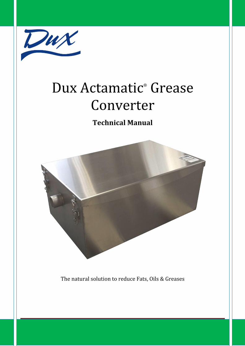
Dux Actamatic® Grease Converter
Technical Manual
The natural solution to reduce Fats, Oils & Greases

Dux Actamatic® Grease Converter
Instructions for Installation and Operation
CONTROLLED DOCUMENT NUMBER: GC QPS13 – Version 3 Page 2
Dux Actamatic Grease Converter Dux Grease Converters have been developed for commercial and industrial premises, specifically where food is prepared or processed. They are a modern and effective means to dealing with the waste water from busy kitchens using a natural bacterial solution to permanently break down fats, oils and greases (FOG’s), to water-soluble, environmentally acceptable effluent levels.
The Dux Grease Converters unique and patented design breaks up the influent as it enters the grease converter through a series of baffles that separate the incoming FOG’s and water to form a float layer contained within the first chamber.
This first chamber is where the Dux Actamatic Liquid is introduced typically around midnight to give the bacteria enough uninterrupted time to start working on the underside of the float layer. The bacteria produce enzymes that begin to liquefy the organic waste which is then digested by the bacteria which begin to multiply. As the bacteria population increases more of the liquefied waste is digested releasing environmentally safe by-products, water, carbon dioxide and energy (heat).
The second chamber restricts the movement of suspended solids containing them and allowing this residue to settle to the base of the tank where after a period of time the tank can be cleaned out on a standard maintenance schedule dependent on the loading of the Dux Grease Converter.
The third and final chamber of the grease converter acts as a further barrier to any solids or FOG’s that might have passed through the previous chambers with the incoming flow before it is discharged to the drain.
Dux Actamatic Liquid
Dux Grease Converters use bioremediation as a natural process where enzymes and bacteria degrade FOG’s. Actamatic Liquid accelerates and enhances the FOG breakdown and should be added on a regulated basis to establish and maintain high bacterial activity.
The Actamatic Liquid is a non-toxic, environmentally friendly product consisting of a specific blend of bacterial strains, concentrated to speed up the degradation and metabolic process, by creating greater surface area for bacterial attack and digestion resulting in beneficial reductions in (FOG’s) Fat oil and Grease loadings. Dux Actamatic Liquid is bio-degradable and will have no adverse affect on the downstream biological cleanup operation. All the bacteria in the Dux Actamatic Liquid have had their identity confirmed and have been classified as non-pathogenic by the laboratories of the National Collection of Industrial Bacteria. Grease is converted permanently into water soluble products and will not reconstitute or redeposit further down the drainage system. Dux Actamatic Liquid when properly used is not harmful to people, wildlife or the environment.
Dux Actamatic Liquid Dispenser
To function efficiently the dux Grease Converter must be dosed regularly, the Dux Prowatch 510T is suitable for all new models and can be readily fitted to units currently in service. The dispenser automatically delivers Dux Actamatic Liquid at a specified time and at the appropriate dosage level. Once set the Dux Prowatch 510T has a security feature that prevents unauthorised or accidental re-programming.

Dux Actamatic® Grease Converter
Instructions for Installation and Operation
CONTROLLED DOCUMENT NUMBER: GC QPS13 – Version 3 Page 3
Dux Actamatic Grease Converter
Dux Pro Watch 510T Dispenser
Dux Actamatic Liquid – Pre diluted and ready to use

Dux Actamatic® Grease Converter
Instructions for Installation and Operation
CONTROLLED DOCUMENT NUMBER: GC QPS13 – Version 3 Page 4

Dux Actamatic® Grease Converter
Instructions for Installation and Operation
CONTROLLED DOCUMENT NUMBER: GC QPS13 – Version 3 Page 5
Product Specifications
Dimensions
Model A (mm) B (mm) C (mm) D (mm) E (mm) F (mm)
GC 5020 775 480 110 210 320 880
GC 5030 595 385 110 395 505 695
GC 5035 990 620 110 250 360 1095
GC 5060 775 480 110 460 570 880
GC 5080 990 670 110 430 540 1095
GC 5100 1100 670 110 430 540 1095
*Minor size variations may occur with manufacturing tolerances
Specifications
Model GC5020 GC5030 GC5035 GC5060 GC5080 GC5100
Treating Capacity per Hour (L) 165 195 330 390 645 746
Functional Liquid Capacity (L) 66 78 132 157 258 298
Unit Weight – Empty (kg) 34 33 50 46 65 70
Connection Size 2” BSP 2” BSP 2” BSP 2” BSP 2” BSP 2” BSP
The GC5060 and GC5080 models are available with a screw down tread plate lid option for in floor
installations. (Part codes GCF5060 & GCF5080)

Dux Actamatic® Grease Converter
Instructions for Installation and Operation
CONTROLLED DOCUMENT NUMBER: GC QPS13 – Version 3 Page 6
A range of sizes for different treating capacities and installations with larger custom made models are
available on request please contact your local Dux representative for more information.
There are options available for larger restaurants and multiple restaurants on the same site. Dux Grease Converters can be custom made to suit the installation and have been manufactured to hold functional liquid capacities of up to 3000 litres with a treating capacity of 7500 litres/hour. As another option two or three Grease Converters can be situated side by side.
Larger standard sizes of Dux Grease Converters are available in the following models:
Model GC 5215 GC 5225 GC5235 GC5250
Functional Liquid Capacity (Litres) 1007 1887 2380 4530
Treating capacity litres/hour 2517 4717 5950 11325
Alternate options available are hangars to lift the Grease Converter off the floor or in floor options that are supplied with a tread lid.
Installation Guidelines
The Dux Actamatic Grease Converter can be installed in any commercial or industrial premises where food is prepared or processed, for the treatment of FOG’s. Being a fully sealed unit it can be installed inside without risk of leakage and/or odour problems.
The following points should be observed.
1. Dux Actamatic Grease Converters must be installed by a licensed plumber and must comply with the New Zealand Building Code. Installations will require approval from the local authority.
2. Inlet and outlet piping must not be less than 50mm. The pipe size and gradient must be in accordance with the New Zealand Building Code G13.
3. If connecting to an existing discharge pipe, ensure it has been cleaned of any sludge/waste build up and/or obstructions.
4. When installing under a bench there must be a minimum clearance of 300mm above the lid to allow proper access for cleaning during pump outs.
5. Ensure the Dux Grease Converter is installed in a part of the building where external access is available for cleaning and pumping equipment.
6. Do not connect dishwashers to the Dux Grease Converter as high temperatures and harsh cleaning chemicals will adversely affect the performance of the micro-organisms and ultimately the performance of the Grease Converter.
7. Ensure there is a dedicated sink not connected to the Dux Grease Converter for the disposal of floor and oven cleaning fluids, as the harsh chemicals will adversely affect the performance of the micro-organisms and ultimately the performance of the Grease Converter. Ensure the hot water temperature emptying or flowing from fixtures into the Dux Grease Converter does not exceed 50°C.

Dux Actamatic® Grease Converter
Instructions for Installation and Operation
CONTROLLED DOCUMENT NUMBER: GC QPS13 – Version 3 Page 7
8. An automatic dispenser must be installed when using a Dux Grease Converter.
9. Ensure that the distance between the last fixture and the Dux Grease Converter is not greater than 8 metres. This will avoid the solidification of FOG’s before it reaches the Grease Converter.
10. Waste disposal units should not discharge into the Dux Grease Converter otherwise bottom solids will build up quickly and block the unit outlet.
11. In-sink screens or dry basket arrestors must be fitted to limit the entry of food scraps into the system. The Dux Actamatic Grease Converter is designed to treat sink wash water containing FOG’s and not kitchen scraps or raw meat.
12. Tighten the lid hinges and ensure that the inlet and outlet connections are properly sealed to maintain an air/watertight installation.
13. An inspection/sampling point must be installed on the outlet as close as practicable to the Dux Actamatic Grease Converter.
14. For improved performance of the Dux Actamatic Grease Converter an air vent to the outside of the building should be installed, place the air vent before the inlet of the Dux Grease Converter. Oxygen can further assist the bioremediation process. Ecoworld can offer an aeration pump that can be retrofitted to the Dux Grease Converter which will further enhance the effectiveness of the Grease Converter. Note: This aeration pump is not part of the standard Dux Grease Converter but can be purchased separately from Ecoworld.

Dux Actamatic® Grease Converter
Instructions for Installation and Operation
CONTROLLED DOCUMENT NUMBER: GC QPS13 – Version 3 Page 8
Selecting the Right Dux Grease Converter for your Business
Contact your local Dux or Ecoworld representative for advice about the Dux Grease Converter that will suit
your kitchen and meet your local authority’s requirements. The larger your Dux Grease Converter is, the
better the result will be. Large Dux Grease Converters help stabilise the bacterial environment and provide a
larger surface area between the FOG float layer and the water where the breakdown reaction occurs.
Sizing of the Dux Grease Converter
The following is a guide only, local authorities may have different requirements for the sizing of Grease
Converters and should be adhered to. Factors such as the food type being prepared and the cleaning
procedures within the kitchen will have an impact on the sizing so if you are in doubt contact your local Dux or
Ecoworld representative for more information.
There are two recommended methods used to establish the size of Dux Grease Converter suitable for an
installation.
The first method is calculated from the volume of the fixtures that are to be connected and discharging
effluent to the Dux Grease Converter per hour, you may also need to consider the tap water flow rate in an
establishment where tap water is constantly flowing from fixtures into the Dux Grease Converter during
operating hours.
Calculate the volume of each fixture (sink) in litres by:
Width x Length x Depth (mm) = Total Volume of Fixtures (Litres)
1,000,000
Average size Guide to Fixtures
Type of Fixture Approx. Size (mm) Approx.
Volume (litres) Quantity Total Volume
(Litres)
Hand wash Sink 270 x 330 x 155 12
Domestic Single Sink 380 x 420 x 200 30
Domestic Double Sink 380 x 420 x 200 x 2 60
Commercial Sink 380 x 455 x 255 44
Commercial Double Sink 380 x 455 x 300 x 2 88
Commercial Potwash Sink 760 x 455 x 255 88
Total Volume of Fixtures (litres)
Once the total volume of the fixtures is determined the loading factor must be estimated, this is solely dependant on the style of cooking or food preparation that will take place within the establishment. The total

Dux Actamatic® Grease Converter
Instructions for Installation and Operation
CONTROLLED DOCUMENT NUMBER: GC QPS13 – Version 3 Page 9
fixture volume should then be multiplied by the estimated frequency of use per hour. The total is then matched to the treating capacity per hour of the Dux Grease Converters.
Example: A Kitchen has three fixtures that they wish to connect to a Dux Grease Converter, 1 x hand wash sink, 1 x commercial and 1 x commercial potwash sink.
Total volume in litres = 144 litres
As there is a reasonable turnover of customers it is envisaged there would be three full uses of the fixtures per hour (432 litres/hour used). Looking at the specifications of the Dux Grease converters on page 5 the GC 5060 has a treating capacity of 390 litres/hr and the GC 5080 645 litres/hr.
Taking into account extra loading during peak periods it would be advisable to use the GC 5080.
The second method of estimating the Dux Grease Converter size required for a restaurant utilises the volume in litres required to service a seat.
This can be found in the New Zealand Building Code G13 and recognises that an average of 5 litres per seat is allowable however Dux Industries Ltd feel this is not a true reflection on how much water is used and feel this figure should be increased to 7 litres per hour, this gives a more realistic usage rate in a busy popular restaurant. Using this figure the following would be the recommended values.
Model GC 5020 GC 5030 GC5035 GC5060 GC5080 GC5100 GCE35 GCE50
Treating capacity litres/hour 165 195 330 390 645 746 210 350
Restaurant seats 0 - 24 0 - 28 0 - 47 0 - 56 0 - 90 0 - 106 0 - 30 0 - 50

Dux Actamatic® Grease Converter
Instructions for Installation and Operation
CONTROLLED DOCUMENT NUMBER: GC QPS13 – Version 3 Page 10
Daily Dosing
Dux Actamatic Liquid is supplied in a ‘ready to use’ container formulated for optimal use. Diluting the liquid will result in reduced effectiveness of the bacteria and may ultimately destroy the product.
The amount of Dux Actamatic Liquid required for dosing depends on the model of Dux Grease Converter. The table below gives a daily dosage guide for the Dux Prowatch 510T Dispenser.
Model Required Daily Dose (ml)
Pro Watch 510T Dispenser
Dosage Time (min:sec)
GC 5020 12 1:00
GC 5030 16 1:20
GC 5035 20 1:40
GC 5060 32 2:40
GC 5080 36 3:00
GC 5100 40 3:20
GCE 5035 20 1:40
GCE 5050 32 2:40
Note: Larger size Grease Converters can be custom built to suit any particular requirement and dosing information will be supplied on request. The Pro watch Dispenser run time applies only to the mains powered Dux Pro Watch 510T.
The above table is a guide only and daily dosing requirements should be discussed with your Dux or Ecoworld representative.
Actamatic Fluid has been pre-diluted for optimal use, diluting the fluid further will result in reduced
effectiveness of the bacteria.
IMPORTANT: Dux Actamatic Liquid is the only approved product to be used with the Dux Actamatic Grease
Converter. The use of any other product(s) may affect the performance of the unit which will void any
warrantee’s and may cause unnecessary additional service costs to return the Dux Actamatic Grease
Converter back to its optimum operating performance.

Dux Actamatic® Grease Converter
Instructions for Installation and Operation
CONTROLLED DOCUMENT NUMBER: GC QPS13 – Version 3 Page 11
Procedure for Start Up and Initial Dosing
This procedure is required when a Grease Converter is first put into service AND after a pump out which must
be carried out by the Dux appointed service agent Ecoworld.
Day 1 Fill the Dux Grease Converter with water. This is best achieved by emptying the fixture(s) into the unit
until the outlet starts to discharge.
Set the pump for daily dosing as per the pump instruction sheet. The recommended time for dosing is
at close down when there is minimal flow rate through the unit which will allow the most effective
micro-biological activity. During that time the bacterial colony will rejuvenate to maintain the bio-
remediation process.
When the kitchen is closed add 100ml of Dux Actamatic Liquid with 250ml of warm water. Pour the
solution into a fixture that empties into the Dux Grease Converter and flush it down with warm water.
6 Months Remove the lid to check the condition of the Dux Grease Converter.
The Grease Converter is working correctly if:
Little or no odour.
A consistency of thick soup.
No dry deposit build-up on the sides.
No caked deposits floating on the surface.
No FOG build up in the discharge lines.
Review the dosing/operational performance.
Ongoing Having established the correct dosing/operational performance at the time of commissioning, the dosing/operational performance should be checked every six months or in accordance to local authority guidelines and requirements.
Maintenance
It is essential to enter into a service agreement with Ecoworld the Dux appointed service agents of the Dux
Actamatic Grease Converters to ensure that the Grease Converter is maintained at optimal running efficiency
over the course of its working life at the establishment.
Ecoworld NZ 2003 Ltd. can be contacted on:
Tel: 0800 109 202
www.ecoworld.co.nz
The benefits of using Ecoworld as the authorised Dux Agent includes:
Warrantee validation on your Dux Grease Converter

Dux Actamatic® Grease Converter
Instructions for Installation and Operation
CONTROLLED DOCUMENT NUMBER: GC QPS13 – Version 3 Page 12
Your business is compliant with local trade waste bylaws
Optimum performance and cost effective operation from your Dux Grease Converter
Less wear and tear on your equipment
Decreased pump out requirement
Pump out Requirements
A pump out should be based on the operational performance of the individual units in service, with full pump outs occurring when required. As part of the Ecoworld Service Agreement, the Ecoworld service agent will let you know when a pump out will be required.
During pump out servicing the internals of the Dux Grease Converter should be thoroughly cleaned including the baffle rollers and outlet trap.
Service must include the cleaning out of bottom solids content.
Whenever the lid is removed it is most important to check the seal condition and ensure the seal is unbroken and still serviceable. Spare seals can be purchased through Dux or Ecoworld. To ensure no odour can escape the Dux Grease Converter please check all latches are firmly locked in place.
Best Management Practices
Ensure an in-sink strainer or dry basket arrestor is fitted to any sink connected to the Dux Grease Converter. This will reduce the build up of solids at the bottom of the unit increasing the period between pump outs.
Put all food scraps into a separate container for disposal, Grease Converters are designed for sink wash water containing FOG’s.
Ensure proper/regular and appropriate Actamatic Liquid dosage.
Keep a back up supply of Actamatic Liquid on hand. Dux Actamatic Liquid should be stored in a cool dark place.
Have the Grease Converter inspected/serviced by the Dux appointed service agents Ecoworld at least every six months.
Ensure after any pump out that the Dux Grease Converter is started as per the initial dosing instructions contained within this booklet.
Do not use products other than Dux Actamatic Liquid as this is the only Dux approved product. Using other products will affect the performance of the Grease Converter.
Do not allow dishwashers to discharge into the Grease Converter as the heat and chemicals will interfere with the performance of the micro-organisms.
Do not empty cleaning liquids containing harsh chemicals such as floor cleaners or oven cleaners into fixtures that empty into the Grease Converter. Caustic or acidic chemicals will kill the micro-organisms and result in reduced bioremediation.

Dux Actamatic® Grease Converter
Instructions for Installation and Operation
CONTROLLED DOCUMENT NUMBER: GC QPS13 – Version 3 Page 13
Do not empty deep fryer fat/oil into the Dux Grease Converter; these should go into a disposal container.
Do not put food grinder/waste disposal into the Grease Converter as this will increase the suspended solids and bottom solids content resulting in shorter times between pump outs.
Do not fill the Grease Converter with hot effluent in excess of 55°C.
Dux Actamatic® Grease Converter Pump out Procedure
The following procedure has been designed to ensure that the grease converter is cleaned properly during a pump out situation. Following this procedure will ensure that the grease converter has been cleaned correctly thereby maximising the duration between required pump outs and must be adhered to in all cases. 6 monthly inspections It is standard practice that the lid on all grease converters be lifted completely on a 6 monthly interval by a certified service agent or at other times when unforeseen circumstances arise such as blockages and/or spillages. This inspection includes assessing all internal chambers and components of the grease converter, i.e. entry baffles, central holding and exit chambers. Once an inspection is completed by a service agent the agent will inform the manager/owner on site whether a pump out is required or not, and whether any other corrective measures are required. Dux Actamatic® Grease Converter Pump out Procedure Pump Truck Tools required for pumping out the Dux Actamatic® Grease Converter: Power driver with 5mm Hex bit or 5mm ball headed Hex screwdriver; wide bladed spatula; flat bladed screwdriver; Philips head screwdriver; suction device with 50mm hose.
1. Ensure that no waste water will be allowed through the grease converter during cleaning 2. Unclip all four clips on the grease converter lid or remove all screws from around the perimeter of the
grease converter lid using a suitable power tool, (power driver with Hex bit or ball headed Hex screwdriver). If applicable carefully set screws aside, noting any damaged screws. (Replacement screws are available through Dux or Ecoworld)
3. Carefully remove the entire grease converter lid, taking care not to damage the closed cell foam seal and set aside. Screw down lids may be carefully prised up with a wide bladed spatula or a couple of screw drivers. Clipped lids should only require to be lifted slightly to break the grip of the seal before being removed. If damage to the seal is noted, advise the site manager. (Replacement seals are available through either Dux or Ecoworld).
4. Carefully remove the inspection plate, (if fitted) on the outlet trap inside the grease converter. This plate need not be replaced and can be discarded.
5. Using the suction device empty all chambers of the grease converter of water as well as all liquid and semi-liquid FOG’s. for the most part, all liquid etc. may be suctioned out from the main, central chamber of the grease converter as any liquid in the other chambers will naturally be drawn under the baffles into this chamber. Both inlet and outlet chambers should still be suctioned to clear any remaining liquid. Solid material in the main chambers, (particularly the inlet and outlets) too large to be suctioned out should be removed by hand. NOTE: advise the site manager if this is the case as it may indicate incorrect use of the sinks etc. connected to the grease converter.
6. Once the liquid has been removed, use the broad bladed spatula to scrape down all walls of the grease converter, the faces of the upright baffles into the grease converter chambers plus the internal

Dux Actamatic® Grease Converter
Instructions for Installation and Operation
CONTROLLED DOCUMENT NUMBER: GC QPS13 – Version 3 Page 14
and external walls of both the inlet and outlet chambers and the ends of the inlet and outlet pipes. Similarly, carefully scrape the inlet chamber rollers, placing as much as possible of the matter and particulates into the main chamber. Any solid layer of matter and particulates on the bottom of the main chamber or the horizontal plates of the inlet chamber should also be ‘disturbed’ at this point.
7. Use the spatula to clean down the grease converter lid, disposing of the grease and particulates into the grease converter.
8. Using the suction device once again, suction out all of the matter and particulates scraped off the grease converter walls, baffles and lid.
9. Partially refill the grease converter with a hose or run the tap on a sink that is connected to the grease converter to wash down the interior walls and baffles.
10. Refill the grease converter by turning on the taps on the attached sink/s for at least 10 minutes to carry out a flow test on the grease converter ensuring that no blockages have occurred during the pump out.
11. Replace the lid on the grease converter and secure all clips or screws, (Caution- do not over tighten the screws and take care not to damage the seal).
12. Complete the council/local body, company and site specific paperwork. Once the pump out has been completed, including being re-filled a 100ml ‘restart’ dose of Actamatic® liquid may be administered via a sink attached to the grease converter. With the older screw down lid versions of the Grease Converters it is important to ensure that the lid is completely removed for the pump out, a pump out cannot be achieved by removing the centre inspection port hole only.

Dux Actamatic® Grease Converter
Instructions for Installation and Operation
CONTROLLED DOCUMENT NUMBER: GC QPS13 – Version 3 Page 15
Warranty
Dux Industries Limited guarantees the Dux Actamatic Grease Converter against manufacturing defect and faulty workmanship for a period of 5 years from date of installation. The warranty requires you to fill out the details on the warranty card and post to Dux within 1 month of installation.
Note: Installation workmanship is not covered by this warranty and should be discussed with the installer.
The following is to be completed by the installer at the time of the installation and this booklet is to be kept with the Grease Converter.
Grease Converter Installation Date: _____________________________________________________
Grease Converter Model: _____________________________________________________________
Dispenser Model: ___________________________________________________________________
Installed By: _______________________________________________________________________
Name of Premises: __________________________________________________________________
IMPORTANT:
For future reference, please leave these installation instructions with the owner or kitchen manager.
For further information:
Dux: Ecoworld NZ 2003 Ltd
Contact Centre Tel: 0800 367 389 Tel: 0800 109 202
www.dux.co.nz www.ecoworld.co.nz