Embed Size (px)
Citation preview

Betriebsanleitung • Operating InstructionsP
K 0
20
3 B
E/H
(0
70
8)
DuoLine™
Rotary Vane Pumps
DUO 20 M
DUO 20 MC

2
Table of contents
Table of contents
1 About this manual. . . . . . . . . . . . . . . . . . . . . . . . . . . . . . . . . . . . . . 31.1 Validity. . . . . . . . . . . . . . . . . . . . . . . . . . . . . . . . . . . . . . . . . . . . . . . . 31.2 Conventions . . . . . . . . . . . . . . . . . . . . . . . . . . . . . . . . . . . . . . . . . . . 3
2 Safety . . . . . . . . . . . . . . . . . . . . . . . . . . . . . . . . . . . . . . . . . . . . . . . . 52.1 Safety precautions . . . . . . . . . . . . . . . . . . . . . . . . . . . . . . . . . . . . . . 52.2 Proper use. . . . . . . . . . . . . . . . . . . . . . . . . . . . . . . . . . . . . . . . . . . . . 52.3 Improper use . . . . . . . . . . . . . . . . . . . . . . . . . . . . . . . . . . . . . . . . . . . 6
3 Transport and Storage . . . . . . . . . . . . . . . . . . . . . . . . . . . . . . . . . . 73.1 Transport. . . . . . . . . . . . . . . . . . . . . . . . . . . . . . . . . . . . . . . . . . . . . . 73.2 Storage . . . . . . . . . . . . . . . . . . . . . . . . . . . . . . . . . . . . . . . . . . . . . . . 7
4 Product description . . . . . . . . . . . . . . . . . . . . . . . . . . . . . . . . . . . . 84.1 Product identification. . . . . . . . . . . . . . . . . . . . . . . . . . . . . . . . . . . . . 84.2 Function . . . . . . . . . . . . . . . . . . . . . . . . . . . . . . . . . . . . . . . . . . . . . . 9
5 Installation . . . . . . . . . . . . . . . . . . . . . . . . . . . . . . . . . . . . . . . . . . . 105.1 Setting up the pump . . . . . . . . . . . . . . . . . . . . . . . . . . . . . . . . . . . . 105.2 Connecting the vacuum side. . . . . . . . . . . . . . . . . . . . . . . . . . . . . . 105.3 Connecting the exhaust side. . . . . . . . . . . . . . . . . . . . . . . . . . . . . . 115.4 Connecting to the mains power supply . . . . . . . . . . . . . . . . . . . . . . 115.5 Filling up the operating fluid . . . . . . . . . . . . . . . . . . . . . . . . . . . . . . 155.6 Operations Monitoring (Option). . . . . . . . . . . . . . . . . . . . . . . . . . . . 16
6 Operation . . . . . . . . . . . . . . . . . . . . . . . . . . . . . . . . . . . . . . . . . . . . 176.1 Before switching on the pump. . . . . . . . . . . . . . . . . . . . . . . . . . . . . 176.2 Switching on the pump . . . . . . . . . . . . . . . . . . . . . . . . . . . . . . . . . . 176.3 Pumping condensable vapours. . . . . . . . . . . . . . . . . . . . . . . . . . . . 176.4 Switching off the pump . . . . . . . . . . . . . . . . . . . . . . . . . . . . . . . . . . 19
7 Maintenance . . . . . . . . . . . . . . . . . . . . . . . . . . . . . . . . . . . . . . . . . 207.1 Precautions . . . . . . . . . . . . . . . . . . . . . . . . . . . . . . . . . . . . . . . . . . . 207.2 Changing the operating fluid . . . . . . . . . . . . . . . . . . . . . . . . . . . . . . 217.3 Cleaning or changing the silencer. . . . . . . . . . . . . . . . . . . . . . . . . . 23
8 Shutdown. . . . . . . . . . . . . . . . . . . . . . . . . . . . . . . . . . . . . . . . . . . . 248.1 Shutting down for longer periods . . . . . . . . . . . . . . . . . . . . . . . . . . 248.2 Restarting the pump . . . . . . . . . . . . . . . . . . . . . . . . . . . . . . . . . . . . 248.3 Disposal . . . . . . . . . . . . . . . . . . . . . . . . . . . . . . . . . . . . . . . . . . . . . 24
9 Malfunctions . . . . . . . . . . . . . . . . . . . . . . . . . . . . . . . . . . . . . . . . . 259.1 Troubleshooting . . . . . . . . . . . . . . . . . . . . . . . . . . . . . . . . . . . . . . . 26
10 Service . . . . . . . . . . . . . . . . . . . . . . . . . . . . . . . . . . . . . . . . . . . . . . 27
11 Spare parts . . . . . . . . . . . . . . . . . . . . . . . . . . . . . . . . . . . . . . . . . . 2811.1 Spare parts package . . . . . . . . . . . . . . . . . . . . . . . . . . . . . . . . . . . . 28
12 Accessories . . . . . . . . . . . . . . . . . . . . . . . . . . . . . . . . . . . . . . . . . . 30
13 Technical data . . . . . . . . . . . . . . . . . . . . . . . . . . . . . . . . . . . . . . . . 3113.1 Dimensions . . . . . . . . . . . . . . . . . . . . . . . . . . . . . . . . . . . . . . . . . . . 31

About this manual
1 About this manual
1.1 ValidityThis operating manual is for customers of Pfeiffer Vacuum. It describes the func-
tioning of the designated product and provides the most important information for
safe use of the unit. The description follows applicable EU guidelines. All informa-
tion provided in this operating manual refer to the current state of the product's de-
velopment. The documentation remains valid as long as the customer does not
make any changes to the product.
Up-to-date operating instructions can also be downloaded from
www.pfeiffer-vacuum.net.
Applicable docu-
ments
*also available via www.pfeiffer-vacuum.net
1.2 Conventions
Safety instructions The safety instructions in Pfeiffer Vacuum operating manuals are the result of risk
evaluations and hazard analyses and are oriented on international certification
standards as specified by UL, CSA, ANSI Z-535, Semi-S1, ISO 3864 and DIN 4844.
In this document, the following hazard levels and information are considered:
DUO 20 M/MC Operating instructions
Safety information for vacuum pumps "Safety Guide" PT 0300 BN*
Declaration of Conformity Part of this document
Operating instructions for accessories (order-specifically) see section "accessories"*
DANGER
Immediate danger
Death or very severe injuries occur.
WARNING
Possible danger
Death or injuries may occur.
CAUTION
Possible danger
Medium to slight injuries may occur.
NOTE
Command or note
Command to perform an action or information about properties, the disregarding of which may result in damage to the product.
3

About this manual
Pictograph
definitions
Instructions in the
text
Work instruction: here you have to do something.
Abbreviations used C version: Corrosive gas version
Symbols used The following symbols are used consistently throughout in all illustrations:
Vacuum flange
Exhaust flange
Gas ballast valve
Power connection
Prohibition of an action or activity in connection with a
source of danger, the disregarding of which may result in
serious accidents.
Warning of a displayed source of danger in connection
with operation of the unit or equipment.
Command to perform an action or task associated with a
source of danger, the disregarding of which may result in
serious accidents.
V
G
4

Safety
2 Safety
2.1 Safety precautions
• Do not expose any body parts to the vacuum.
• Observe the safety and accident prevention regulations.
• Check regularly that all safety precautions are being complied with.
• Do not carry out any unauthorised modifications or conversions to the pumps.
• Depending on the operating and ambient conditions, the surface temperature of
the pumps may rise above 70 °C. Use suitable finger guards if necessary.
• When returning the pumps to us please note the instructions in the Service sec-
tion.
The following safety instructions are only valid for the disassembly of the drive
system for a vacuum pump with a magnetic coupling:
• When disassembling the drive system from the pump housing, the strong mag-
netic field may influence the function and operational reliability of electrical and
electronic devices.
• Persons with cardiac pacemakers must keep away from the magnetic coupling.
Danger to life!
• Disassembled magnetic couplings must be kept away from computers, data sto-
rage media and other electronic components.
• Keep the disassembled components of the magnetic coupling separate at all ti-
mes. Danger of crushing!
• Do not allow any magnetised parts into the vicinity of the magnetic coupling.
Danger of injury!
2.2 Proper use
• The vacuum pump may only be used to generate a vacuum.
• Installation, operating and maintenance regulations must be complied with.
• Other accessories than those described in this manual must not be used without
the agreement of Pfeiffer Vacuum.
NOTE
Duty to inform
Each person involved in the installation, operation or maintenance of the vacuum pump must read and observe the safety-related parts of these operating instructions.
Absolute observe the safety information for vacuum pumps (PT 0300 BN) !The operator is obligated to make operating personnel aware of dangers originating from the vacuum pump, the pumped medium and the entire system.
NOTE
CE conformity
The manufacturer's declaration of conformity becomes invalid if the operator modifies the original product or installs additional components.
Following installation into a plant and before commissioning, the operator must check the entire system for compliance with the valid EU directives and reassess it accordingly.
5

Safety
2.3 Improper useImproper use will cause all claims for liability and guarantees to be forfeited. Im-
proper use is deemed to be all use for purposes deviating from those mentioned
above, especially:
• Pumping of corrosive gases (exception: pumps in C version).
• Pumping of explosive media.
• Operation of the pump in potentially explosive areas.
• Pumping of gases containing impurities such as particles, dusts and condensate;
note the vapour compatibility levels of the pump.
• Pumping of substances that tend to sublime.
• Use of the vacuum pump to generate pressure.
• Pumping of liquids.
• The use of operating fluids not specified by Pfeiffer Vacuum.
• Connection to pumps or units which are not suitable for this purpose according
to their operating instructions.
• Connection to units which have touchable and voltage carrying parts.
6

Transport and Storage
3 Transport and Storage
3.1 Transport
Transport instructions
Remove the locking cap from the vacuum and exhaust flange immediately be-
fore connecting!
– Check the protective strainer, paying attention to the o-ring.
Use only the handle or the crane eye on the top side of the pump to lift the pump.
– Is the pumps weight > 25 kg lift the pump by a crane.
Fig. 1: Transporting the pump
3.2 Storage
Check that all the openings on the pump are securely closed.
Store the pump in a cool, dry place; preferably at room temperature (approx.
20°C).
– For a longer period of storage, seal the pump in a PE bag with drying agents
enclosed.
– For a period of storage longer than one year, it is recommended to carry out
maintenance and change the operating fluid.
7

Product description
4 Product description
4.1 Product identificationTo correctly identify the product when communicating with Pfeiffer Vacuum, al-
ways have the information from the rating plate available and use it:
• Pump model and model number
• Serial number
• Type and amount of operating fluid
• Date of manufacture
Please find the voltage range and motor-related data on the separately attached
motor rating plate.
Fig. 2: Product identification on the rating plate
Scope of delivery • Pump with motor (power cord/power switch --> dependent on the motor type)
• Operating fluid P3 (for standard pump)
• Cone strainer and centering ring with O-ring
• Locking cap for vacuum and exhaust flange
• Operating instructions
Differences between
the pump type
D-35641 Asslar
Mod.: DUO 10Mod.-Nr.: PK D62 105 D
Ser.- Nr.: 3454440
S : max. 10 m /hOil : P3 1.0 l Mass : 24 kg
n : 1800 1/min
(N )23
max.Made in Germany 2005/01
Pump type Pump versions
DUO 20 M Standard version of pump
DUO 20 MC
C version of pump; differences from the standard version:
• Operating fluid F4• Encapsulated can of the magnetic coupling at the pump system• Vane material changed• Gas ballast valve with dosable flushing gas connection
8

Product description
4.2 FunctionThe vacuum pumps of the DuoLine® are dual stage rotary vane pumps and are
used primarily for rough and medium vacuum applications. The pumps are fitted
with a hydraulically controlled vacuum safety valve which, when the pump is at a
stillstand, closes the vacuum chamber vacuum tight and at the same time vents the
pump. The integrated magnetic coupling functions free of contact and friction.
Therefore it is not subjected to any mechanical wear and is completely mainte-
nance free compared to a conventional shaft feedthrough.
Fig. 3: Rotary Vane Pump DUO 20 M
1 Vacuum flange
2 Exhaust flange
15 Main switch
28 Casing
42 Gas ballast valve
80 Base plate
110 Sight glass
198 Operating fluid filler screw
198aOperating fluid drain screw
1198 2 1542
110 8028198a
9

Installation
5 Installation
5.1 Setting up the pump
Installation location Observe the following requirements when setting up the pump:
• Note the load-bearing capacity of the mounting surface.
• Maximum installation altitude 2000 m (above mean sea level)
• Permissible ambient temperature: +12 ... +40°C
• Maximum relative humidity 85%
Fig. 4: Setting up
Fill up with operating fluid before operating the first time (see p. 15, chap. 5.5).
– Amount and type according to rating plate
Always place the pump on a firm, even surface.
– Where stationary installation is involved, anchor the pump on site.
When installing the pump in a closed housing, ensure there is sufficient air cir-
culation.
– Sightglass and gas ballast valve must be visible and readily accessible.
– Voltage and frequency information given on the motor rating plate must be
visible.
5.2 Connecting the vacuum side
Before attaching the piping at the vacuum flange remove locking cap and insert
protective strainer with the respective O-ring.
The connection between the pump and the recipient should be kept as short as
possible.
– Depending on the pump type, use metallic hoses or PVC hoses with flange
connections.
– Separators, filters etc. may be installed upstream to protect the pump (see ac-
cessories). However, please observe the loss of pumping capacity due to the
conductivity of the accessories.
max. 10 °
> 35 mm
10

Installation
5.3 Connecting the exhaust side
Choose the cross-section of the exhaust line to be at least the size of the nominal
connection diameter of the vacuum pump's exhaust connection.
Piping to the pump must be suspended or supported.
– Forces from the piping system must not be allowed to act on vacuum pumps.
Lay piping from the pump, sloping downward so that no condensate can flow
back into the pump; otherwise fit a condensate separator.
– If an air trap is created in the system then a device for draining condensation
water must be provided at the lowest point.
5.4 Connecting to the mains power supplyDepending on the pump type, different motor versions are possible:
• Single phase motor for fixed voltage with a built-in thermal protection switch,
mains switch and connecting cable.
• Single phase motor with switchable broad range voltage motor with a built-in
thermal protection switch and mains connection socket.
• Three phase motor (without switch and mains cable).
CAUTION
High pressure in the exhaust line!
Danger of damage to the seals and danger of the pump bursting.
Install the line without shut-off valves on the exhaust side.If there is danger of a build-up of excess pressure (> 1500 mbar abs.) in the lines, observe all official accident prevention safety regulations.If the exhaust gases are being extracted, the exhaust pressure must be at least 250 mbar greater than the pressure at the intake side.
WARNING
Emission of toxic substances from the exhaust!
Danger of poisoning from emitted gases or vapours, which can be detrimental to health and/or can pollute the environment, depending on the particular application.
Comply with the applicable regulations when working with toxic substances.Only officially approved filter systems may be used to separate out these substances.
DANGER
Voltage-bearing elements
Danger to life from electric shock.
The electrical connection can be carried out only by trained and authorised electrici-ans.Ensure the system is adequately earthed.
CAUTION
Excess voltage!
Danger of destroying the motor.
Power connections must comply with local regulations. Voltage and frequency infor-mation given on the motor rating plate must correspond to the mains voltage and frequency values.To protect the motor and supply cable in case of malfunction, mains fuse protection must be implemented.
11

Installation
Single phase broad
range voltage motor
The mains voltage must be determined on-site each time before the pump is in-
stalled or moved to a different location.
Fig. 5: Connection diagram (terminal box)
Changing the voltage range
Disconnect the pump from the power supply.
Set the rocker switch "S" in the motor terminal box to the desired voltage range.
WARNING
Danger of injury from moving parts!
After power failure or motor shutdown due to overheating, the motor may restart auto-matically.
Secure the motor so that it cannot be switched on while any work is being performed on the pump.If necessary, dismantle the pump from the installation for inspection.
NOTE
The transmission power of the pump’s magnetic coupling is so great that there
is no overload protection for the motor.
NOTE
Overvoltage!
An incorrect voltage range setting can damage the motor.
Disconnect the pump from the power supply.Only change the voltage range when the pump is disconnected from the power mains.
R Capacitor relay
S Voltage selector switch
T Thermal protection switch
U Mains switch
V Mains connection socket
P
B
T
R
S
U
V
J
T7
T3
T3
T1
T2
T8
T4
T4 CP
CD
2
3
1
B6
A5
A1
L N
B6
B2
B4
B2
A5
A3
A1
12

Installation
Motor protection
To protect the motor in case of malfunction, carry out fuse protection in accor-
dance with the regional regulations.
– Select a fuse with slow characteristics.
Three-phase motor Inspection of the direction of rotation
With pumps with three-phase motors is it necessary to check the direction of rota-
tion!
Remove the locking cap from the exhaust flange (if existing).
Switch the pump on briefly (from 2 to 3 sec.).
– The motor and motor fan must turn in a clockwise direction (see the arrow on
the support stand).
If the direction of rotation is incorrect: Swap two phase contacts at the connec-
ting cable.
Fill up the operating fluid.
Motor protection
Pump motors equipped with PTC temperature sensors (3PTC) in the stator wind-
ings can be connected to a PTC resistor tripping device for protection against over-
load.
Tripping devices store the shutdown event and need to be manually switched back
on again via the integrated RESET button or via the external RESET S3. Mains-ON
is detected as an automatic RESET. Other approved motor temperature monitoring
can be used also by the operator.
Set up the connections so that the directional rotation indicated on the pump is
maintained, regardless of the representations in the current flow diagram.
Rocker switch in the terminal box for changing the voltage range
Switch position:
Voltage range:200 ... 230 V/50 Hz
200 ... 240 V/60 Hz
100 ... 110 V/50 Hz
100 ... 120 V/60 Hz
CAUTION
Operating fluids may leak out!
If the direction of rotation is incorrect, there is a danger that operating fluids may leak at the vacuum flange.
Always check the direction of rotation before filling in operating fluid.
13

Installation
Fig. 6: Connection example for a three-phase AC motor with PTC resistor tripping de-vice
USControl voltage
S1OFF button
S2ON button
S3RESET button, external
K1 Contactor
F1 ... F4 Fuses
T1... T3 PTC resistor sensor
H1 Tripping indicator
M Motor, 3-phase
1)Only for devices with two
relay outputs2) Only for MSR type3)Only for order no.:
P 4768 051 FQ
N
L1
M3
L2L3
F1 - F3
K1
10 11
AC 220 ... 240 VUs
F4U V W
S1
S2k1
K1
H1S3
2)
A1 A2 T1 T2 Y2Y1 24 21 22 14 12112) 2) 1) 1) 1)
T1...T3
3)
14

Installation
5.5 Filling up the operating fluidThe type and amount of operating fluid should be visible on the pump's rating
plate for every rotary vane pump.
The delivery consignment for the standard pump contains suffient operating flu-
id for one filling. Pumps for special applications (e.g. for pumping corrosive gases)
can be operated with other operating fluids. These must be defined in accordance
with Pfeiffer Vacuum specifications before initial assembly and ordered separately.
Permissible operating fluids
• P3 (Standard operating fluid)
• F4 (Operating fluid for corrosive gas versions)
• D1 (for special applications and higher operating temperature)
– Final pressure of measurement, depending on the type of gas: < 5·10-2 mbar
Filling up the
operating fluid
Unscrew operating fluid filler screw 198.
Fill up operating fluid.
– Correct filling level during operations: Within the markings at the sightglass
frame.
Fig. 7: Filling up the operating fluid
Screw in operating fluid filler screw 198.
Check operating fluid level only when the pump is warm and running; close
– vacuum flange and gas ballast valve to do so.
– Check operating fluid daily in non-stop operation, otherwise whenever the
pump is switched on. Refilling is possible when the pump is in final vacuum
operation.
NOTE
Guarantees relating to attainment of final pressures and trouble free functioning
of the pump apply only providing one of the permissible operating fluids is used.
max.
min.
198
WARNING
Toxic vapours!
Danger of poisoning when igniting and heating synthetic operating fluids (e.g. F4/F5) above 300°C.
Observe the application instructions of the operating fluid manufacturer.Do not allow operating fluid to make contact with tobacco products; observe safety precautions when handling chemicals.
15

Installation
5.6 Operations Monitoring (Option)A pressure switch can be installed on the side of the support to monitor the oil
pressure of the rotary vane pump during operations. By pressure drop and when
the pump is at rest, the contact of the pressure switch opens. The signal can be
used to control external valves.
Fig. 8: Installation location and circuit diagram of pressure switch
Switching voltage: 5 ... 250 Volt (potential free)
Maximum current: 2 Amp.
Protection type: IP 55
1 + 2 closers = pressureless open
1
2
16

Operation
6 Operation
6.1 Before switching on the pump
Check the operating fluid level in the sightglass.
Compare the voltage and frequency information on the rating plate with the
mains voltage and frequency values.
Check that the exhaust connection allows free flow (max. permissible pressure
1.5 bar absolute).
– Activate the shut-off valves in such a way that they open before or at the same
time as the pump is started.
Protect the pump sufficiently from taking in contaminants by means of suitable
precautions (e.g. dust filters); if necessary, check operating fluid regularly or re-
place at shorter intervals.
6.2 Switching on the pumpThe pump can be switched on in any pressure range.
No special precautions are necessary when pumping dry gases. In order to attain
the lowest possible final pressures, the gas ballast valve should be closed.
Switch on pump at main switch 15.
6.3 Pumping condensable vapoursShould the process gases contain condensable gases present at high percentages,
the rotary vane pump must be operated with a gas ballast (i.e. with an open gas
ballast valve).
Gas ballast valve,
standard version
To avoid condensation in the pump when pumping condensable vapours, ambient
air or alternatively inertgas is periodically fed into the working chamber at the be-
ginning of the compression phase via the gas ballast valve 42.
The gas ballast valve is closed when turning to the right to position 0 and open
when turning to the left to position 1. Intermediate settings are not possible.
CAUTION
Hot surface!
Danger of burns if hot parts are touched. Depending on the operating and ambient conditions, the surface temperature of the pump may rise above 70 °C.
In this case, use suitable finger guards.
CAUTION
Bad final vacuum and damage to the pump!
Danger of condensation and corrosion due to exceeding the water vapour compatibi-lity (see Technical data) during operation without a gas ballast or in case of insufficient supply of flushing gas.
Only pump vapours when the pump is warm and the gas ballast valve is open.When the process has been completed, allow the pump to continue running for about 30 minutes with the vacuum flange closed and the gas ballast open for ope-rating fluid regeneration purposes.
17

Operation
Fig. 9: Standard version 42 of gas ballast valve
Gas ballast valve,
corrosive gas version
If the pumping process requires the connection of flushing gas, the C version of the
gas ballast with the flushing gas connection must be used.
Fig. 10: Corrosive gas version of gas ballast valve
Connect flushing gas at the flushing gas connection.
Set flushing gas pressure; maximum pressure 1.5 bar (absolute).
– Select the type and amount of flushing gas depending on the process; consult
Pfeiffer Vacuum if necessary.
00
1 1
0
1 01
C-Version
CAUTION
Flushing gas pressure higher than allowed endangers the operational reliability
of the pump.
The power input of the pump, the temperature and the ejection of operating fluid will increase.
Observe the maximum permissible flushing gas pressure.Set the amount of flushing gas on site.
18

Operation
6.4 Switching off the pumpThe pump can be switched off in any pressure range.
Rotary vane pumps have an integrated safety valve on the intake side. If the differ-
ential pressure between the exhaust side and the intake side is ≥ 250 mbar, then
the valve closes automatically and vents the pump when the pump is switched off.
Switch the pump off at the mains switch or disconnect from the mains in a secu-
re manner.
Venting the vacuum
chamber
Maintaining the va-
cuum in the chamber
CAUTION
Danger of backflow of operating fluid into the intake line!
Contamination of the connected vacuum system!
Vent the vacuum chamber within 30 s, regardless of the chamber size.For a longer venting process, use an additional shut-off valve and shut off the intake line after switching off the pump.
CAUTION
Danger of backflow of operating fluid into the intake line!
Contamination of the connected vacuum system!
Because the safety valve of the pump is not suitable for longer-term sealing, install an additional shut-off valve in the intake line.Shut off the intake line immediately after switching off the pump.
19

Maintenance
7 Maintenance
7.1 Precautions
Allow the pump to cool to a safe temperature.
Only dismantle the pump as far as necessary in order to repair defects.
Dispose of used operating fluid in compliance with local regulations.
When using synthetic operating fluids or working with toxic substances or sub-
stances contaminated with corrosive gases, the relevant instructions governing
their use must be observed.
Use only alcohol or similar agents for cleaning pump parts.
WARNING
Danger of injury from moving parts!
After power failure or motor shutdown due to overheating, the motor may restart auto-matically.
Secure the motor so that it cannot be switched on while any work is being performed on the pump.If necessary, dismantle the pump from the installation for inspection.
WARNING
Pump parts may be contaminated from pumped media!
Danger of poisoning due to contact with harmful substances.
Decontaminate the pump before carrying out any maintenance work.In the event of contamination, take suitable safety precautions to prevent your health from being harmed by any dangerous substances.
20

Maintenance
Check list for inspec-
tions, maintenance
and overhaul
Certain repair and overhaul work should only be performed by Pfeiffer Vacuum
Service (PV). Pfeiffer Vacuum will be released from all warranty and liability claims
if the required intervals for inspection, maintenance, or overhaul are exceeded or
inspection, maintenance, repair or overhaul procedures are not performed proper-
ly. This also applies if replacement parts other than Pfeiffer Vacuum OEM replace-
ment parts are used.
7.2 Changing the operating fluidThe changing interval for the operating fluid depends on the pump applications,
but should be carried out once a year.
Switch off pump.
Unscrew operating fluid drain screw 198a and drain operating fluid.
Fill the specimen in a test tube or some similar vessel and test by holding
against the light.
The level of deterioration of operating fluid P3 can be read off the colour scale
in accordance with DIN 51578; request the supplementary sheet PK 0219 BN or
download it from the Internet.
Where discolouration is dark yellow to red brown (equivalent to 4 ... 5 on the sca-
le) change operating fluid.
Activity daily as required;
at least
annually
as required;
at least
every 2
years
as required;
at least
every 4
years
Check operating fluid level X
Visual inspection (leak-tightness/oil leaks)
X
Check filter insert of external oil mist filter (if existent)
X
Change filter insert of external oil mist fil-ter (if existent)
X
Change operating fluid X
Cleaning the pump and renew the seals X
Clean gas ballast valve and silencer nozzle
X
Clean the motor fan cap X
Clean or change vacuum safety valve X (PV)
Clean or change exhaust valves X (PV)
Change vanes and hydraulic vane X (PV)
Check or change coupling X (PV)
Depending on the process, the required replacement intervals for lubricants and the intervals for inspection, maintenance and overhaul may be shorter than the guide values specified in the table. Consult with Pfeiffer Vacuum Service if necessary.
NOTE
Depending on the applications, Pfeiffer Vacuum recommends determining the
exact service life of the operating fluid during the first year of operation.
The replacement interval may vary from the guide value specified by Pfeiffer Vacuum depending on the thermal and chemical loads, and the accumulation of suspended par-ticles and condensation in the operating fluid.
WARNING
Hot operating fluid!
Danger of burns when draining due to contact with skin.
Wear suitable protective clothing.Use a suitable collecting vessel.
21

Maintenance
Fig. 11: Draining the operating fluid
Screw in operating fluid drain screw 198a; pay attention to o-ring.
Allow pump to run for a maximum of 5 seconds with the vacuum flange open.
Drain off remaining operating fluid.
– In case of serious contamination, the operating fluid will have to be changed
several times (flushing):
Flushing Fill up with operating fluid to the middle of the sight glass.
Operate the pump with the gas ballast open until the pump has warmed up.
Drain the operating fluid again and check for contamination, flush again if neces-
sary.
Screw the operating fluid drain screw back in.
Fill up with operating fluid and check the filling level (see p. 15, chap. 5.5).
198a
WARNING
Operating fluid may contain toxic substances from the pumped media!
Danger of poisoning from the emission of harmful substances (radioactive, toxic, etc.) from the operating fluid.
Wear suitable protective clothing and respirators.Dispose of operating fluid according to the local regulations
NOTE
Request safety data sheets for operating fluids and lubricants
from Pfeiffer Vacuum or download them from the Internet.
Dispose of operating fluid according to the local regulations.
22

Maintenance
7.3 Cleaning or changing the silencerThe silencer 44 is a nozzle inside the pump housing and cannot be altered; when
dirty it should either be cleaned or replaced.
Dismantling
Unscrew 2 cheesehead screws 182 from the gas ballast valve housing.
Remove the gas ballast valve housing 42 from the casing 28; taking care with o-
ring 148.
Unscrew silencer nozzle 44 and o-ring 138; clean it and replace o-ring 138 if ne-
cessary.
Fig. 12: Gas ballast valve with silencer nozzle 44
42 Gas ballast valve housing
44 Silencer nozzle
138 O-ring
141 O-ring
148 O-ring
148
42
182
44
138138
141
23

Shutdown
8 Shutdown
8.1 Shutting down for longer periodsBefore shutting down the pump, observe the following procedure and adequately
protect the pump system against corrosion:
Switch off pump.
Change operating fluid(see p. 21, chap. 7.2).
Start the pump and allow the pump to warm up.
Fill up the pump with new operating fluid to the top edge of the sightglass.
Close vacuum flange and exhaust flange with locking caps.
8.2 Restarting the pumpVisually inspect the inner of the pump before taking it into operation. If there is ev-
idence of rust on the parts of the pump which form the housing then do not take it
into operation and contact Pfeiffer Vacuum Service.
With reference to DIN 7716 and the manufacturer's specifications we recommend
replacing the installed elastomer parts after 2 years.
If drying pearls were inserted then they should be removed now. Improper
handling can cause failure of the pump.
8.3 DisposalProducts or parts thereof (mechanical and electrical components, operating fluids,
etc.) may cause environmental burden.
Safely dispose of the materials according to the locally applicable regulations.
CAUTION
Emission of operating fluid!
Danger of the operating fluid being emitted at the exhaust flange if overfilled.
Drain the operating fluid to the normal level before restarting the pump.
24

Malfunctions
9 MalfunctionsPlease note the following instructions should the pump malfunction:
DANGER
Strong magnetic field in the vicinity of the drive system!
Danger to life for persons with cardiac pacemakers when the drive system is disas-sembled.
Persons with cardiac pacemakers must not enter the area of the magnetic field.Disassembled magnetic couplings must be kept away from computers, data storage media and other electronic components.
CAUTION
Hot surface!
Danger of burns if hot parts are touched. The surface temperature of the pump may rise above 105 °C in case of malfunction.
Carry out work on the pump only after it has cooled to a safe temperature.
NOTE
Motor overload!
Depending on the malfunction (e.g. blocking during cold start), the motor may not be sufficiently protected by the built-in thermal protection switch from damage through overheating.
Implement an additional network safety device.
25
Malfunctions
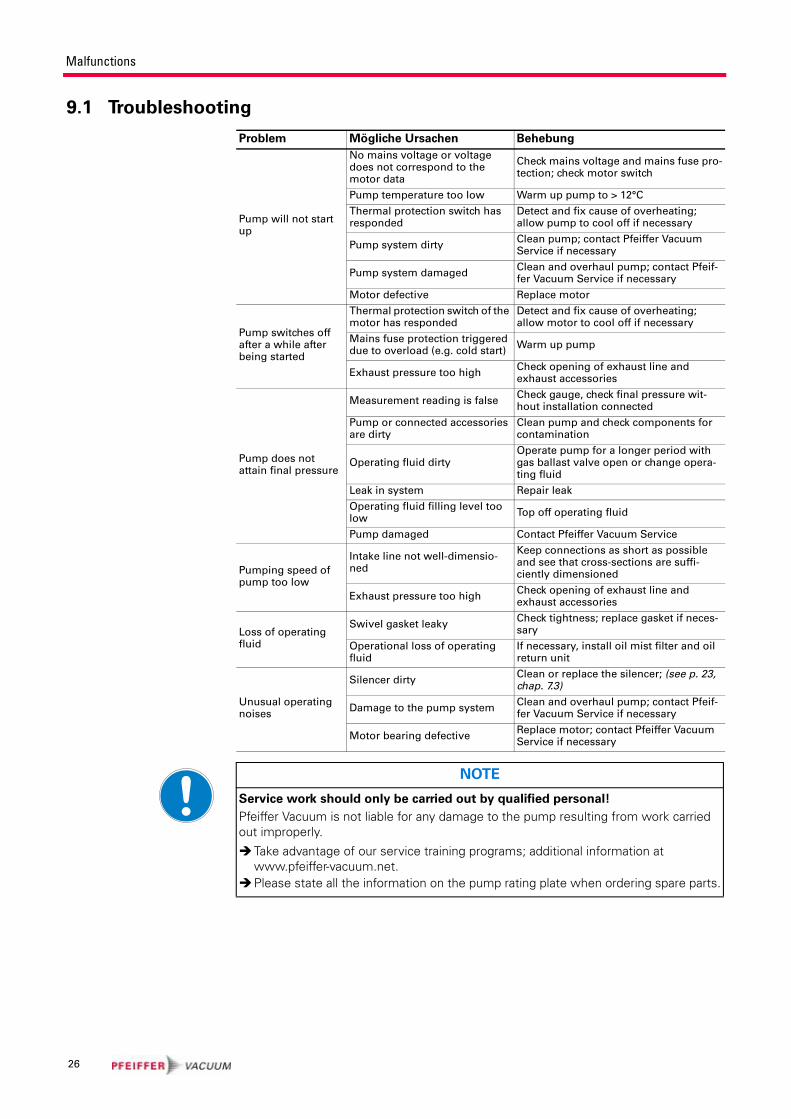
9.1 Troubleshooting
Problem Mögliche Ursachen Behebung
Pump will not start up
No mains voltage or voltage does not correspond to the motor data
Check mains voltage and mains fuse pro-tection; check motor switch
Pump temperature too low Warm up pump to > 12°C
Thermal protection switch has responded
Detect and fix cause of overheating; allow pump to cool off if necessary
Pump system dirtyClean pump; contact Pfeiffer Vacuum Service if necessary
Pump system damagedClean and overhaul pump; contact Pfeif-fer Vacuum Service if necessary
Motor defective Replace motor
Pump switches off after a while after being started
Thermal protection switch of the motor has responded
Detect and fix cause of overheating; allow motor to cool off if necessary
Mains fuse protection triggered due to overload (e.g. cold start)
Warm up pump
Exhaust pressure too highCheck opening of exhaust line and exhaust accessories
Pump does not attain final pressure
Measurement reading is falseCheck gauge, check final pressure wit-hout installation connected
Pump or connected accessories are dirty
Clean pump and check components for contamination
Operating fluid dirtyOperate pump for a longer period with gas ballast valve open or change opera-ting fluid
Leak in system Repair leak
Operating fluid filling level too low
Top off operating fluid
Pump damaged Contact Pfeiffer Vacuum Service
Pumping speed of pump too low
Intake line not well-dimensio-ned
Keep connections as short as possible and see that cross-sections are suffi-ciently dimensioned
Exhaust pressure too highCheck opening of exhaust line and exhaust accessories
Loss of operating fluid
Swivel gasket leakyCheck tightness; replace gasket if neces-sary
Operational loss of operating fluid
If necessary, install oil mist filter and oil return unit
Unusual operating noises
Silencer dirtyClean or replace the silencer; (see p. 23, chap. 7.3)
Damage to the pump systemClean and overhaul pump; contact Pfeif-fer Vacuum Service if necessary
Motor bearing defectiveReplace motor; contact Pfeiffer Vacuum Service if necessary
NOTE
Service work should only be carried out by qualified personal!
Pfeiffer Vacuum is not liable for any damage to the pump resulting from work carried out improperly.
Take advantage of our service training programs; additional information at www.pfeiffer-vacuum.net.Please state all the information on the pump rating plate when ordering spare parts.
26

Service
10 ServicePfeiffer Vacuum offers first-class service!
• Maintenance/repairs on the spot by Pfeiffer Vacuum field service
• Maintenance/repairs in the nearby service center or service point
• Fast replacement with exchange products in mint condition
• Advice on the most cost-efficient and quickest solution
Detailed information and addresses at: www.pfeiffer-vacuum.net (Service).
Maintenance and repairs in the Pfeiffer Vacuum ServiceCenter
The following steps are necessary to ensure a fast, smooth servicing process:
Download the RMA1) form and contamination declaration.
Fill in the RMA form and send it by fax or e-mail to your service address.
Enclose the RMA confirmation of receipt from Pfeiffer Vacuum in the shipment.
Fill in the contamination declaration and enclose it in the shipment (required!).
Dismantle all accessories.
Drain operating fluid/lubricant.
Drain cooling medium, if used.
Send the pump or unit in its original packaging if at all possible.
Returning contaminated vacuum pumps
Units which are microbiologically, explosively or radioactively contaminated will
not be accepted by Pfeiffer Vacuum as a matter of principle. Hazardous substances
are substances and compounds in accordance with the hazardous goods directive
(current version). Should pumps be contaminated or the contamination declara-
tion be missing, Pfeiffer Vacuum will decontaminate the pumps at your cost.
Returning contaminated pumps or units
Neutralise the pump/unit by flushing it with nitrogen or dry air.
Close off all openings so that they are air-tight.
Seal the pump/unit in suitable protective film.
Only return the pump/unit in a suitable and sturdy transport container.
All service orders are carried out exclusively according to our repair conditions for
vacuum units and components.
1) RMA: Return Material Authorization
27

Spare parts
11 Spare parts
11.1 Spare parts packageThe spare parts packages listed here are only applicable for standard models.
Please state all information on the rating plate when ordering spare parts. Other
spare parts than those described in this manual must not be used without the
agreement of Pfeiffer Vacuum.
Spare parts
package
Pump type Revision
index
Article no. Parts according to the
exploded view on the follow-
ing page
Set of sealsDUO 20 M
DUO 20 MC
without / as from "A"
PK E30 008 -T76, 112, 138, 141, 144, 147, 148, 149, 150, 152, 154, 155, 156, 158, 162.
Maintenance kit
DUO20 M
DUO 20 MC
without / as from "A"
PK E31 007 -T 144, 162.
Discharge val-ves
DUO 20 M
DUO 20 MC
without / as from "A"
PK E38 006 -T
PK E38 005 -T7, 8, 9, 10.
Overhaul kit
DUO 20 Mwithout / as from "A"
PK E32 011 -TPK E30 008 -T, 7, 8, 9, 10, 32, 44, 51, 102, 106, 110, 114, 193, 195.
DUO 20 MCwithout / as from "A"
PK E32 013 -TPK E30 008 -T, 7, 8, 9, 10, 32, 44, 51, 102, 106, 110, 114, 193, 195.
Vacuum safety valve
DUO 20M
DUO 20 MC
without / as from "A"
PK E34 007 -T30, 32, 34, 35, 96, 101, 106, 108, 147, 152, 154, 158, 188, 204, 207, 208, 220, 250.
Pumping sys-tem, com-plete and tested with P3
DUO 20 Mwithout / as from "A"
PK E33 020 -T 4.1
Pumping sys-tem, com-plete and tested with D1
DUO 20 Mwithout / as from "A"
PK E33 023 -T 4.1
Pumping sys-tem, com-plete and tested with F4
DUO 20 Mwithout / as from "A"
PK E33 021 -T 4.1
Pumping sys-tem, com-plete and tested with F4
DUO 20 MCwithout / as from "A"
PK E33 022 -T 4.1
Float valveIDUO 20 M
DUO 20 MC
without / as from "A"
PK E35 006 -T 102, 154, 158, 184, 188.
Coupling ki
DUO 20 Mwithout
as from "A"
PK E36 010-T
PK E36 009 -T
18, 20, 22, 24, 27, 155, 162.
18, 20, 22, 24, 155, 162.
DUO 20 MCwithout
as from "A"
PK E36 010 -T
PK E36 009 -T
18, 20, 22, 24, 27, 155, 162.
18, 20, 22, 24, 155, 162.
28

Spare parts
r
Exploded view DUO 20 M
2 Rotor
3 Hydraulic pump
4 Pump cylinder
5 Support plate
6 Bearing cover
7 Vanes, rough stage
8 Vanes, medium stage
9 Hydraulic vane
10 Compression spring, vanes
18 Magnetic coupling,
drive side
20 Magnetic coupling,
pump side
22 Washer
24 Can
27 Intermediate flange for
motor
30 Housing, vacuum safety
valve
32 Valve plate, vacuum safety
valve
34 Valve cover, vacuum safety
valve
35 Strainer
42 Gas ballast valve housing (furthe
parts see Section. 7.3.)
44 Silencer nozzle
51 Plate spring
76 Rapid action coupling
96 Exhaust valve, (stage 1)
101 Punched disk
102 Valve plate
104 Valve trap
106 Hydraulic piston
108 Compression spring
110 Sight glass
112 Sight glass seal
114 Rubber foot
116 Flange
138 O-ring
141 O-ring
144 O-ring
147 O-ring
148 O-ring
149 O-ring
150 O-ring
152 O-ring
154 O-ring
155 O-ring
156 O-ring
158 O-ring
162 O-ring
180 Allan head screw
183 Allan head screw
184 Allan head screw
185 Allan head screw
188 Allan head screw
193 Compression spring, over
pressure valve
195 Ball
204 Circlip
207 Compression spring
208 Washer
220 Screw
250 Compression spring
252 Allan head screw
76 208/ 184
990210
64
184 193 102104
18 2 x 200* 27
180
144
114
155/158
20208/ 24185/183*
180 23
204
101207
34 106 108 30
188
96
32 147 250
152
154/1582 x 220/2 x 208 35
195
7/10 8/10
149
252
110112
5
156
162
184/22
150
116
2 x 220
144 5144
208
42(138/141/148) }
4.1
4.1
29

Accessories
12 AccessoriesFurther detailed accessories are contained in the Pfeiffer Vacuum printed Cata-
logue or the Online Catalogue.
1 Filled with zeolite
Description Size Number Comments/
(relevant manual)
Dust separator STP 025 DN25 ISO-KF PK Z60 106 PK 0120 BN
Oil mist filter ONF 25 L DN25 ISO-KF PK Z40 158 PK 0213 BN
Oil return unit ONFR PK 196 172 -T PK 0213 BN
Condensate separator KAS 25 L DN25 ISO-KF PK Z10 033 PK 0220
Cooling trap KLF 025 DN25 ISO-KF on request PD 0015 BN
Adsorption filter FAK 025 DN25 ISO-KF on request PD 0017 BN
Adsorption filter FBL 025 DN25 ISO-KF on request PD 0017 BN
Zeolite trap ZFO 0251 DN25 ISO-KF on request PD 0016 BN
Sight glass adapter, complete PK 196 141 -T PD 0004 BN
Sight glass adapter with operating fluid level control
PK 196 157 -T PD 0004 BN
Pressure switch for operations monitoring
PK 196 449
Operating fluid P3 1 litre PK 001 106 -T
Operating fluid P3 5 litre PK 001 107 -T
Operating fluid P3 20 litre PK 001 108 -T
Operating fluid F4 1 litre PK 005 887 -T
Operating fluid F4 0,5 litre PK 005 886 -T
Operating fluid F4 0,25 litre PK 005 885 -T
Operating fluid D1 1 litre PK 005 875 -T
Operating fluid D1 5 litre PK 005 876 -T
Operating fluid D1 20 litre PK 005 877 -T
PTC Tripping unit P 4768 051 FQ
30

Technical data
13 Technical data
13.1 Dimensions
Fig. 13: Dimensions DUO 20 M
Technical data DUO 20 M DUO 20 MC
Flange (in) DN 25 ISO-KF DN 25 ISO-KF
Flange (out) DN 25 ISO-KF DN 25 ISO-KF
Pumping speed at 50 Hz 20 m3/h 20 m3/h
Pumping speed at 60 Hz 24 m3/h 24 m3/h
Ultimate pressure with gas ballast ≤ 1·10-2 mbar ≤ 1·10-2 mbar
Ultimate pressure without gas ballast ≤ 5·10-3 mbar ≤ 5·10-3 mbar
Leakage rate safety valve ≤ 1 * 10-4 mbar * l/s ≤ 1 * 10-4 mbar * l/s
Water vapor tolerance at 50 Hz 30 mbar 30 mbar
Water vapor tolerance at 60 Hz 36 mbar 36 mbar
Water vapor capacity 50 Hz 400 g/h 400 g/h
Water vapor capacity 60 Hz 550 g/h 550 g/h
Emission sound pressure level without gas ballast
≤ 55 dB (A) ≤ 57 dB (A)
Pump fluid filling 1 l 1 l
Rated power 50 Hz 0.55 kW 0.55 kW
Rated power 60 Hz 0.66 kW 0.66 kW
Nominal rotation speed at 50 Hz 1380 rpm 1400 rpm
Nominal rotation speed at 60 Hz 1660 rpm 1680 rpm
Switch noyes, with 2 m mains cable and safety plug
Weight 33 kg 39 kg
Pump with three phase motor Pump with single phase motor
A 542 mm 568 mm
H212 (without motor protection switch)
223 (with motor protection switch)245 mm
K 239 mm 568 mm
303
178
DN 25 ISO-KF
76,5
K
99 114238
266A
210
H
3 Ø7
113
112 ... 140 (Ø7)166188
8
1825
1,5
12,5
31

Declaration of conformity
pursuant to the following EU directives:
• Machinery 98/37/EEC (Annex II A)• Low Voltage 2006/95/EEC• Electromagnetic Compatibility 89/336/EEC
We hereby certify, that the product specified below is in accordance with the pro-
vision of EU Machinery Directive 98/37/EEC, EU Electromagnetic Compatibility
Directive 89/336/EEC and the EU Low Voltage Directive 2006/95/EEC.
DuoLine®/DuoLine™
DUO 20 M/MC
Guidelines, harmonised standards, national standards in languages and specifi-
cations which have been applied:
DIN EN ISO 12100-1/2 EN 294 EN 60335-1, 41 EN 61010
EN 60204 EN 50081-1, -2 EN 1012-2
Signatures:
Pfeiffer Vacuum GmbH
Berliner Straße 43
35614 Asslar
Germany
(M.Bender)
Managing Director
(Dr. M. Wiemer)
Managing DirectorCE/2007

Pfeiffer Vacuum Technology AG · Headquarters/Germany
Tel. +49-(0) 64 41-8 02-0 · Fax +49-(0) 64 41-8 02-2 02 · [email protected] · www.pfeiffer-vacuum.net
Vacuum is nothing, but everything to us!
Turbopumps
Rotary vane pumps
Roots pumps
Dry compressing pumps
Leak detectors
Valves
Components and feedthroughs
Vacuum measurement
Gas analysis
System engineering
Service