Embed Size (px)
Citation preview
The data contained in this publication is intended merely as a guide. FIAT reserves the right to modify the models and versions described in this booklet at any time for technical and commercial reasons.
If you have any further questions please consult your FIAT dealer. Printed in recycled paper without chlorine. O W N E R H A N D B O O K
F I A T D U C A T OENGLISH
DUCATO LUM GB 17-12-2008 9:57 Pagina 1

Dear Customer,
Thank you for choosing Fiat and congratulations on your choice of a Fiat Ducato.
We have written this handbook to help you get to know all the features of your vehicle and use it in the best possible way.
You are recommended to read it right through before taking to the road for the first time. You will find information, tips and im-portant warnings regarding the driving of your vehicle to help you derive the maximum from the technological features of your Fi-at Ducato.
You are recommended to carefully read the warnings and indications, marked with the respective symbols:
personal safety;
vehicle integrity;
environmental protection.
The enclosed Warranty Booklet lists the services that Fiat offers to its Customers:
❒ the Warranty Certificate with terms and conditions for maintaining its validity;
❒ the range of additional services available to Fiat Customers.
Enjoy the read. Happy motoring!
This Owner Handbook describes all the versions of the Fiat Ducato.As a consequence, you should only consider the information which is related to the engine
and bodywork version of the vehicle you have purchased.
001-036 DUCATO LUM EN 11-02-2010 13:53 Pagina 1

REFUELLING
Only refuel with automotive diesel conforming to theEuropean standard EN 590.
The use of other products or mixtures may damage theengine beyond repair and consequently cause the war-ranty to be void depending on the damage caused.
STARTING THE ENGINE
Make sure that the handbrake is engaged; set the gearshiftlever to neutral; fully depress the clutch without press-ing the accelerator, then turn the ignition key to MAR andwait for the warning lights Y and m to go off; turnthe ignition key to AVV and release it as soon as the en-gine has started.
PARKING ON FLAMMABLE MATERIAL
The catalytic converter develops high temperature dur-ing operation. Do not park on grass, dry leaves, pineneedles or other flammable material: fire hazard.
RESPECTING THE ENVIRONMENT
The vehicle is fitted with a system that allows continu-ous diagnosis of the components correlated with emis-sions to ensure better respect for the environment.
ELECTRICAL ACCESSORIES
If, after buying the vehicle, you decide to add electricalaccessories (with the risk of gradually draining the bat-tery), visit a Fiat Dealership. They can calculate the over-all electrical requirement and check that the vehicle elec-tric system can support the required load.
CODE CARD
Keep it in a safe place, not in the vehicle. Make sure youhave the electronic code with you at all times.
SCHEDULED MAINTENANCE
Correct vehicle servicing is essential for ensuring it staysin tip-top condition and safeguards its safety features, itsenvironmental friendliness and low running costs for a long time to come.
THE OWNER HANDBOOK CONTAINS…
... important information, advise and warnings for a cor-rect use, driving safety and maintenance of your vehi-cle over time. Pay special attention to the symbols "(personal safety) # (protecting the environment)! (riskof serious damage to the vehicle).
VERY IMPORTANT
K
�
�
001-036 DUCATO LUM EN 11-02-2010 13:53 Pagina 2

3
DASHBOARD AND CONTROLS
SAFETY
STARTING AND DRIVING
WARNING LIGHTSAND MESSAGES
IN AN EMERGENCY
MAINTENANCE AND CARE
TECHNICAL SPECIFICATIONS
INDEX
DASHBOARD AND CONTROLS
DASHBOARD
The presence and position of the controls, instruments and gauges may vary depending on the version.
1. Fixed side air – vents – 2. Adjustable side air vents – 3. Left steering column stalk: external lights – 4. Instrument andwarning light panel – 5. Right steering column stalk: windscreen wiper controls, rear window wiper, trip computer – 6. Adjustable central air vents – 7. Car radio (for versions/markets, where provided) – 8. Passenger side glove com-partment/front air bag (for versions/markets, where provided) – 9. glove compartment – 10. Cigar lighter/12 V socket– 11. HVAC controls – 12. Controls on dashboard – 13. Gear lever – 14. Ignition device – 15. Steering wheel adjust-ment lever – 16. Driver side front airbag – 17. Control plate: lamp/headlamp alignment adjustment/digital display/ multifunction display.
F0N0320mfig. 1
001-036 DUCATO LUM EN 11-02-2010 13:53 Pagina 3
4
DASHBOARD AND CONTROLS
SAFETY
STARTING AND DRIVING
WARNING LIGHTSAND MESSAGES
IN AN EMERGENCY
MAINTENANCE AND CARE
TECHNICAL SPECIFICATIONS
INDEX
F0N0002mfig. 2
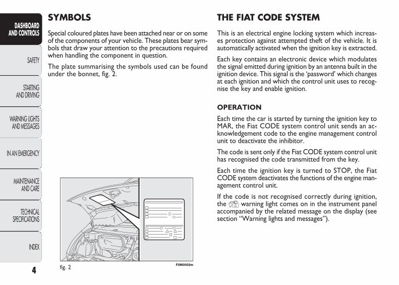
THE FIAT CODE SYSTEM
This is an electrical engine locking system which increas-es protection against attempted theft of the vehicle. It isautomatically activated when the ignition key is extracted.
Each key contains an electronic device which modulatesthe signal emitted during ignition by an antenna built in theignition device. This signal is the ‘password’ which changesat each ignition and which the control unit uses to recog-nise the key and enable ignition.
OPERATION
Each time the car is started by turning the ignition key toMAR, the Fiat CODE system control unit sends an ac-knowledgement code to the engine management controlunit to deactivate the inhibitor.
The code is sent only if the Fiat CODE system control unithas recognised the code transmitted from the key.
Each time the ignition key is turned to STOP, the FiatCODE system deactivates the functions of the engine man-agement control unit.
If the code is not recognised correctly during ignition, the Y warning light comes on in the instrument panel accompanied by the related message on the display (seesection “Warning lights and messages”).
SYMBOLS
Special coloured plates have been attached near or on someof the components of your vehicle. These plates bear sym-bols that draw your attention to the precautions requiredwhen handling the component in question.
The plate summarising the symbols used can be foundunder the bonnet, fig. 2.
001-036 DUCATO LUM EN 11-02-2010 13:53 Pagina 4
5
DASHBOARD AND CONTROLS
SAFETY
STARTING AND DRIVING
WARNING LIGHTSAND MESSAGES
IN AN EMERGENCY
MAINTENANCE AND CARE
TECHNICAL SPECIFICATIONS
INDEX
THE KEYS
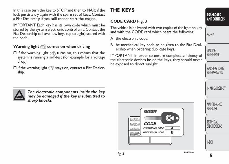
CODE CARD Fig. 3
The vehicle is delivered with two copies of the ignition keyand with the CODE card which bears the following:
A the electronic code;
B he mechanical key code to be given to the Fiat Deal-ership when ordering duplicate keys.
IMPORTANT In order to ensure complete efficiency ofthe electronic devices inside the keys, they should neverbe exposed to direct sunlight.
In this case turn the key to STOP and then to MAR; if thelock persists try again with the spare set of keys. Contacta Fiat Dealership if you still cannot start the engine.
IMPORTANT Each key has its own code which must bestored by the system electronic control unit. Contact theFiat Dealership to have new keys (up to eight) stored withthe code.
Warning light Y comes on when driving
❒ If the warning light Y turns on, this means that thesystem is running a self-test (for example for a voltagedrop).
❒ If the warning light Y stays on, contact a Fiat Dealer-ship.
The electronic components inside the keymay be damaged if the key is submitted tosharp knocks.
F0N0003mfig. 3
001-036 DUCATO LUM EN 11-02-2010 13:53 Pagina 5

F0N0800mfig. 4
To refit it proceed as follows:
❒ keep button B pressed and move the metal insert A;
❒ release button B and turn the metal insert A until hear-ing the proper locking click.
KEY WITH REMOTE CONTROL fig. 4
The metal insert A is retractable and it operates:
❒ the ignition switch;
❒ the door locks;
❒ opening and closing of the fuel plug.
To extract the metal insert, press button B and
6
DASHBOARD AND CONTROLS
SAFETY
STARTING AND DRIVING
WARNING LIGHTSAND MESSAGES
IN AN EMERGENCY
MAINTENANCE AND CARE
TECHNICAL SPECIFICATIONS
INDEX
All the keys and the CODE card must behanded over to the new owner when sellingthe vehicle.
Only press button B with the key awayfrom your body, specifically from your eyes
and from objects which could get damaged (e.g.your clothes). Do not leave the key unattended, be-cause someone, a child especially, may accidentallypress the button while handling the key.
WARNING
Button Q is used for unlocking the front doors.
Button Á is used for locking all the doors.
Button P is used for unlocking the load compartmentdoors.
The passenger’s compartment lights will come on for a preset time when the doors are unlocked.
001-036 DUCATO LUM EN 11-02-2010 13:53 Pagina 6
7
DASHBOARD AND CONTROLS
SAFETY
STARTING AND DRIVING
WARNING LIGHTSAND MESSAGES
IN AN EMERGENCY
MAINTENANCE AND CARE
TECHNICAL SPECIFICATIONS
INDEX
F0N0801mfig. 5 F0N0114mfig. 6
Request for additional remote controls
The system can recognise up to 8 remote controls. Shoulda new remote control be necessary, contact a Fiat Deal-ership and be ready to present the CODE card, a personalidentity document and the vehicle ownership documents.
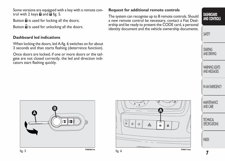
Some versions are equipped with a key with a remote con-trol with 2 keys Á and Ë fig. 5.
Button Á is used for locking all the doors;
Button Ë is used for unlocking all the doors.
Dashboard led indications
When locking the doors, led A-fig. 6 switches on for about3 seconds and than starts flashing (deterrence function).
Once doors are locked, if one or more doors or the tail-gate are not closed correctly, the led and direction indi-cators start flashing quickly.
001-036 DUCATO LUM EN 11-02-2010 13:53 Pagina 7
F0N0802mfig. 7 F0N0337mfig. 8
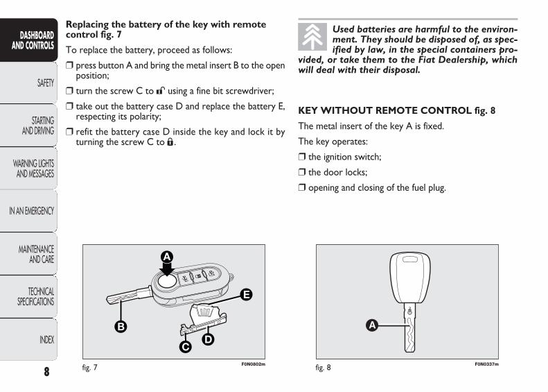
KEY WITHOUT REMOTE CONTROL fig. 8
The metal insert of the key A is fixed.
The key operates:
❒ the ignition switch;
❒ the door locks;
❒ opening and closing of the fuel plug.
Replacing the battery of the key with remotecontrol fig. 7
To replace the battery, proceed as follows:
❒ press button A and bring the metal insert B to the openposition;
❒ turn the screw C to : using a fine bit screwdriver;
❒ take out the battery case D and replace the battery E,respecting its polarity;
❒ refit the battery case D inside the key and lock it byturning the screw C to Á .
8
DASHBOARD AND CONTROLS
SAFETY
STARTING AND DRIVING
WARNING LIGHTSAND MESSAGES
IN AN EMERGENCY
MAINTENANCE AND CARE
TECHNICAL SPECIFICATIONS
INDEX
Used batteries are harmful to the environ-ment. They should be disposed of, as spec-ified by law, in the special containers pro-
vided, or take them to the Fiat Dealership, whichwill deal with their disposal.
001-036 DUCATO LUM EN 11-02-2010 13:53 Pagina 8
Type of key
Key without remote control
Key with remote control
Direction indicators flashing (only with key with remote control)
Deterrence led
9
DASHBOARD AND CONTROLS
SAFETY
STARTING AND DRIVING
WARNING LIGHTSAND MESSAGES
IN AN EMERGENCY
MAINTENANCE AND CARE
TECHNICAL SPECIFICATIONS
INDEX
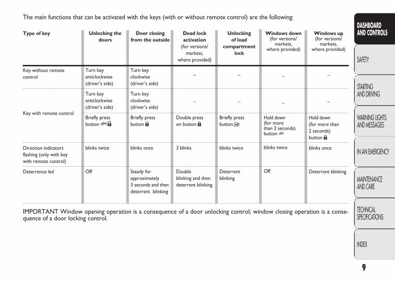
The main functions that can be activated with the keys (with or without remote control) are the following:
Unlocking the doors
Turn key anticlockwise (driver’s side)
Turn key anticlockwise (driver’s side)
Briefly press button Q/Ë
blinks twice
Off
Door closing from the outside
Turn key clockwise (driver’s side)
Turn key clockwise (driver’s side)
Briefly press button Á
blinks once
Steady for approximately 3 seconds and thendeterrent blinking
Dead lock activation
(for versions/markets,
where provided)
–
–
Double press on button Á
3 blinks
Double blinking and then deterrent blinking
Unlocking of load
compartment lock
–
–
Briefly press button P
blinks twice
Deterrent blinking
IMPORTANT Window opening operation is a consequence of a door unlocking control; window closing operation is a conse-quence of a door locking control.
Windows up (for versions/
markets, where provided)
–
–
Hold down (for more than 2 seconds) button Á
blinks once
Deterrent blinking
Windows down(for versions/
markets, where provided)
–
–
Hold down (for more than 2 seconds) button Q
blinks twice
Off
001-036 DUCATO LUM EN 11-02-2010 13:53 Pagina 9
There are a maximum number of acoustic/visual cycles.When this is reached the system returns to normal op-eration.
The antilift protection may be turned off by means of theappropriate key (see “Antilift protection” paragraph over-leaf).
IMPORTANT The engine stop function is guaranteed bythe Fiat CODE, which is automatically activated when theignition key is extracted from the starter device.
TURNING THE ALARM ON
With the doors and bonnets closed and the ignition keyeither turned to STOP or removed, point the key with theremote control towards the vehicle and press and releasethe lock button.
Excluding some markets, the system produces an acous-tic warning (beep) and enables door locking.
The switching on of the alarm is preceded by an self-di-agnosis stage: if a fault is detected, the system producesanother acoustic signal.
In this case, turn the alarm off by pressing the ‘releasedoors/release load compartment’ button, check the doorsand bonnet are properly closed and turn the alarm backon by pressing the lock button.
ELECTRONIC ALARM (for versions/markets where provided)
The alarm, in addition to all the remote control functionsdescribed previously, is controlled by the receiver locat-ed under the dashboard near the fuse box.
ALARM TRIPPING
The alarm intervenes in the following cases:
❒ when one of the doors or bonnet is opened illegiti-mately (perimeter protection);
❒ when the ignition system is started up (ignition keyrotated to MAR);
❒ when the battery cables are cut;
❒ when the vehicle is lifted or tilted.
Depending on the market, the activation of the alarm caus-es the activation of the siren and the direction indicators(for about 26 seconds). Alarm tripping and the numberof cycles depend on the sales market.
10
DASHBOARD AND CONTROLS
SAFETY
STARTING AND DRIVING
WARNING LIGHTSAND MESSAGES
IN AN EMERGENCY
MAINTENANCE AND CARE
TECHNICAL SPECIFICATIONS
INDEX
001-036 DUCATO LUM EN 11-02-2010 13:53 Pagina 10
11
DASHBOARD AND CONTROLS
SAFETY
STARTING AND DRIVING
WARNING LIGHTSAND MESSAGES
IN AN EMERGENCY
MAINTENANCE AND CARE
TECHNICAL SPECIFICATIONS
INDEX
F0N0232mfig. 8a
ANTI-LIFT PROTECTION
The anti-lift protection system consists in a sensor whichdetects any change in vehicle tilting with a view to identi-fying any possible vehicle lifting, though partial (e.g. whena tyre is removed).
The sensor also detects minor changes of the vehicle trimangle both along the longitudinal and transverse axle.
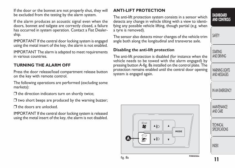
Disabling the anti-lift protection
The anti-lift protection is disabled (for instance when thevehicle needs to be towed with the alarm engaged) bypressing button A-fig. 8a installed on the control plate. Theprotection remains enabled until the central door openingsystem is engaged again.
If the door or the bonnet are not properly shut, they willbe excluded from the testing by the alarm system.
If the alarm produces an acoustic signal even when thedoors, bonnet and tailgate are correctly closed, a failurehas occurred in system operation. Contact a Fiat Dealer-ship.
IMPORTANT If the central door locking system is engagedusing the metal insert of the key, the alarm is not enabled.
IMPORTANT The alarm is adapted to meet requirementsin various countries.
TURNING THE ALARM OFF
Press the door release/load compartment release buttonon the key with remote control.
The following operations are performed (excluding somemarkets):
❒ the direction indicators turn on shortly twice;
❒ two short beeps are produced by the warning buzzer;
❒ the doors are unlocked.
IMPORTANT If the central door locking system is releasedusing the metal insert of the key, the alarm is not disabled.
001-036 DUCATO LUM EN 11-02-2010 13:53 Pagina 11
BREAK IN ATTEMPT INDICATION
Any theft attempt is indicated by the turning on of warn-ing light Y on the instrument panel together with thededicated message on the multifunction display (whereprovided), (see section “Warning lights and messages”).
DISABLING THE ALARM
To turn the alarm off completely (for example, if the ve-hicle is not being used for a long time) the vehicle mustbe closed by turning the metal insert in the key in the lockwithout using the remote control.
IMPORTANT If the battery of the key with the remotecontrol goes flat or the system fails, the alarm can beswitched off by placing the key in the ignition switch andturning it to MAR.
12
DASHBOARD AND CONTROLS
SAFETY
STARTING AND DRIVING
WARNING LIGHTSAND MESSAGES
IN AN EMERGENCY
MAINTENANCE AND CARE
TECHNICAL SPECIFICATIONS
INDEX
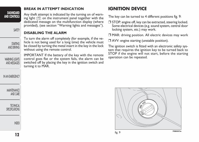
IGNITION DEVICE
The key can be turned to 4 different positions fig. 9:
❒ STOP: engine off, key can be extracted, steering locked.Some electrical devices (e.g. sound system, central doorlocking system, etc.) may work.
❒ MAR: driving position. All electric devices may work
❒ AVV: engine starting (unstable position).
The ignition switch is fitted with an electronic safety sys-tem that requires the ignition key to be turned back toSTOP if the engine will not start, before the starting operation can be repeated.
F0N0007mfig. 9
001-036 DUCATO LUM EN 11-02-2010 13:53 Pagina 12
13
DASHBOARD AND CONTROLS
SAFETY
STARTING AND DRIVING
WARNING LIGHTSAND MESSAGES
IN AN EMERGENCY
MAINTENANCE AND CARE
TECHNICAL SPECIFICATIONS
INDEX
Never extract the key while the vehicle ismoving. The steering wheel would be
locked as soon as the steering wheel is turned. Thisalso applies to cases in which the vehicle is towed.
WARNING
It is absolutely forbidden to carry out anyafter-market operation involving steering
system or steering column modifications (e.g.: in-stallation of anti-theft device). This could badlyaffect performance and safety, invalidate the war-ranty and also result in the non-compliance of thevehicle with approval requirements.
WARNING
If the ignition device is tampered with(e.g.: attempted theft), have it checked
over by a Fiat Dealership as soon as possible.
WARNING
Always remove the key from the vehiclewhen leaving it in order to prevent acci-
dental engagement of the control. Remember toapply the handbrake. Engage first gear if the ve-hicle is parked uphill or reverse if the vehicle isparked downhill. Never leave children unattend-ed in the vehicle.
WARNING
STEERING LOCK
Engagement
When the key is at STOP, remove the key and turn thesteering wheel until it locks.
Switching off
Move the steering wheel slightly as you turn the ignitionkey to MAR.
001-036 DUCATO LUM EN 11-02-2010 13:53 Pagina 13

14
DASHBOARD AND CONTROLS
SAFETY
STARTING AND DRIVING
WARNING LIGHTSAND MESSAGES
IN AN EMERGENCY
MAINTENANCE AND CARE
TECHNICAL SPECIFICATIONS
INDEX
INSTRUMENT PANEL
Versions with digital display
A Speedometer (speed indicator)
B Digital display
C Rev counters
D Engine coolant temperature gaugewith overheating warning light
E Fuel level gauge with reserve warn-ing light
Versions with multifunction display
A Speedometer (speed indicator)
B Multifunction display
C Rev counters
D Engine coolant temperature gaugewith overheating warning light
E Fuel level gauge with reserve warn-ing light
F0N0330m
fig. 10
F0N0331m
fig. 11
001-036 DUCATO LUM EN 11-02-2010 13:53 Pagina 14

15
DASHBOARD AND CONTROLS
SAFETY
STARTING AND DRIVING
WARNING LIGHTSAND MESSAGES
IN AN EMERGENCY
MAINTENANCE AND CARE
TECHNICAL SPECIFICATIONS
INDEX
F0N0332mfig. 12 F0N0013mfig. 13
REV. COUNTER Fig. 13
The rev counter shows the engine rpm.
IMPORTANT The electronic injection control systemgradually shuts off the flow of fuel when the engine is ‘over-revving’ resulting in a gradual loss of engine power.
When the engine is idling, the rev counter may indicate a gradual or sudden increase of the speed.
This is normal and does not indicate a fault. It may becaused, for example, by the operation of the climate con-trol system or fan. In such cases, a slight increase in engineidle speed helps to safeguard the battery charge level.
INSTRUMENTS
The type and background colour of the instruments canvary between different versions.
SPEEDOMETER Fig. 12
It shows the vehicle speed.
001-036 DUCATO LUM EN 11-02-2010 13:53 Pagina 15

F0N0014mfig. 14 F0N0015mfig. 15
ENGINE COOLANT TEMPERATURE GAUGE fig. 15
This shows the temperature of the engine coolant fluidand starts working when the fluid temperature exceedsapprox. 50°C.
Under normal conditions, the needle should hover aroundthe middle of the scale according to the working condi-tions of the vehicle.
C Low engine coolant temperature.
H High engine coolant temperature.
Warning light B may light up (and a message on the mul-tifunction display may appear in certain versions) to indi-cate that the coolant temperature is too high; in this case,stop the engine and contact the Fiat Dealership.
FUEL LEVEL GAUGE Fig. 14
This shows the amount of fuel left in the fuel tank.E tank empty.F tank full (see the instructions provided in paragraph
“Vehicle refuelling” in this section).
The warning light A coming on indicates that there areabout 10-12 litres of fuel remaining in the tank (dependingon the version). Do not travel with the fuel tank almostempty: the gaps in fuel delivery could damage the cata-lyst.
IMPORTANT The needle will point to E and warning lightA will blink to indicate a fault in the system. Contact a FiatDealership to have the system checked.
IMPORTANT It is not advisable to start the additionalheater (Webasto) when fuel is on reserve.
16
DASHBOARD AND CONTROLS
SAFETY
STARTING AND DRIVING
WARNING LIGHTSAND MESSAGES
IN AN EMERGENCY
MAINTENANCE AND CARE
TECHNICAL SPECIFICATIONS
INDEX
001-036 DUCATO LUM EN 11-02-2010 13:53 Pagina 16
17
DASHBOARD AND CONTROLS
SAFETY
STARTING AND DRIVING
WARNING LIGHTSAND MESSAGES
IN AN EMERGENCY
MAINTENANCE AND CARE
TECHNICAL SPECIFICATIONS
INDEX
If the needle reaches the red area, stop theengine immediately and contact a FiatDealership.
The failure of the fifth symbol to come on should not betaken as a fault or the fact that there is not enough oil inthe sump.
IMPORTANT To find out the correct oil quantity, alwayscheck on the dipstick (see paragraph “Checking levels” inthe section “Maintenance and care”).
After a few seconds, the symbol display indicating theamount of engine oil disappears and:
❒ When the next scheduled servicing is near, the timeto the next service is displayed and the warning light õ lights up on the instrument panel. When the servicedate is reached, the display shows some dashes.
❒ then, if it is nearly time to change the engine oil, thetime to the next oil change is shown on the top rowof the display and the message “OIL” appears in thelower part of the display. When the service date isreached, the display shows five dashes.
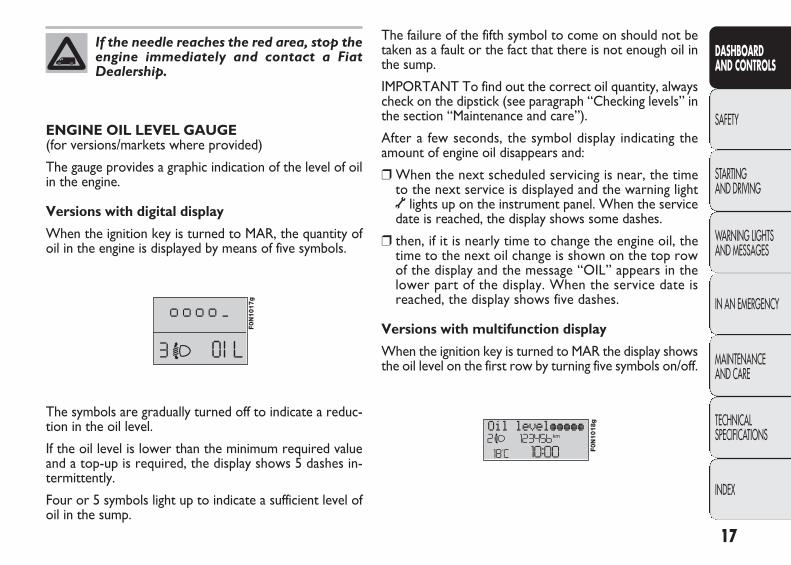
Versions with multifunction display
When the ignition key is turned to MAR the display showsthe oil level on the first row by turning five symbols on/off.
ENGINE OIL LEVEL GAUGE (for versions/markets where provided)
The gauge provides a graphic indication of the level of oilin the engine.
Versions with digital display
When the ignition key is turned to MAR, the quantity ofoil in the engine is displayed by means of five symbols.
F0N1017g
The symbols are gradually turned off to indicate a reduc-tion in the oil level.
If the oil level is lower than the minimum required valueand a top-up is required, the display shows 5 dashes in-termittently.
Four or 5 symbols light up to indicate a sufficient level ofoil in the sump.
F0N1018g
001-036 DUCATO LUM EN 11-02-2010 13:53 Pagina 17
F0N0016mfig. 16
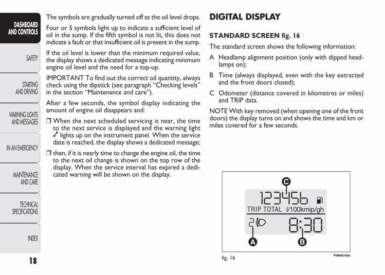
DIGITAL DISPLAY
STANDARD SCREEN fig. 16
The standard screen shows the following information:
A Headlamp alignment position (only with dipped head-lamps on);
B Time (always displayed, even with the key extractedand the front doors closed);
C Odometer (distance covered in kilometres or miles)and TRIP data.
NOTE With key removed (when opening one of the frontdoors) the display turns on and shows the time and km ormiles covered for a few seconds.
The symbols are gradually turned off as the oil level drops.
Four or 5 symbols light up to indicate a sufficient level ofoil in the sump. If the fifth symbol is not lit, this does notindicate a fault or that insufficient oil is present in the sump.
If the oil level is lower than the minimum required value,the display shows a dedicated message indicating minimumengine oil level and the need for a top-up.
IMPORTANT To find out the correct oil quantity, alwayscheck using the dipstick (see paragraph “Checking levels”in the section “Maintenance and care”).
After a few seconds, the symbol display indicating theamount of engine oil disappears and:
❒ When the next scheduled servicing is near, the timeto the next service is displayed and the warning lightõ lights up on the instrument panel. When the servicedate is reached, the display shows a dedicated message;
❒ then, if it is nearly time to change the engine oil, the timeto the next oil change is shown on the top row of thedisplay. When the service interval has expired a dedi-cated warning will be shown on the display.
18
DASHBOARD AND CONTROLS
SAFETY
STARTING AND DRIVING
WARNING LIGHTSAND MESSAGES
IN AN EMERGENCY
MAINTENANCE AND CARE
TECHNICAL SPECIFICATIONS
INDEX
001-036 DUCATO LUM EN 11-02-2010 13:53 Pagina 18
19
DASHBOARD AND CONTROLS
SAFETY
STARTING AND DRIVING
WARNING LIGHTSAND MESSAGES
IN AN EMERGENCY
MAINTENANCE AND CARE
TECHNICAL SPECIFICATIONS
INDEX
fig. 17
SETUP MENU Fig. 18
The menu comprises a series of functions arranged in a cy-cle which can be selected through buttons ▲ and ▼ toaccess the different select operations and settings (setup)given in the following paragraphs.
The setup menu can be activated by briefly pressing but-ton MODE.
Single presses on buttons ▲ and ▼ will scroll the setupmenu options.
Handling modes differ with each other according to thecharacteristic of the option selected.
Selecting a menu option
– Briefly press button MODE to select the menu optionthat needs to be changed;
– press buttons ▲ and ▼ (by single presses) to select thenew setting;
– briefly press button MODE to store the new setting andat the same time go back to the previously selected menuoption.
Selecting “Set Clock”
– Briefly press button MODE to select the first value tochange (hours);
– press buttons ▲ and ▼ (by single presses) to select thenew setting;
– briefly press button MODE to store the new setting andgo to the next setup menu option (minutes);
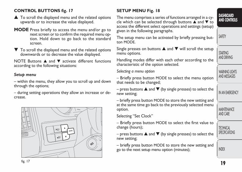
CONTROL BUTTONS fig. 17
▲ To scroll the displayed menu and the related optionsupwards or to increase the value displayed.
MODE Press briefly to access the menu and/or go tonext screen or to confirm the required menu op-tion. Hold down to go back to the standardscreen.
▼ To scroll the displayed menu and the related optionsdownwards or to decrease the value displayed.
NOTE Buttons ▲ and ▼ activate different functions according to the following situations:
Setup menu
– within the menu, they allow you to scroll up and downthrough the options;
– during setting operations they allow an increase or de-crease.
001-036 DUCATO LUM EN 11-02-2010 13:53 Pagina 19
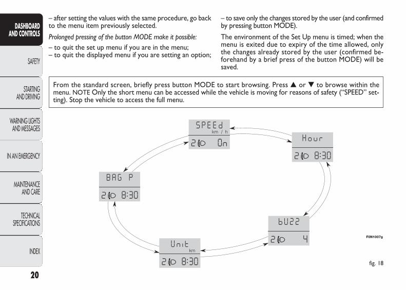
From the standard screen, briefly press button MODE to start browsing. Press ▲ or ▼ to browse within themenu. NOTE Only the short menu can be accessed while the vehicle is moving for reasons of safety (“SPEED” set-ting). Stop the vehicle to access the full menu.
fig. 18
F0N1007g
– after setting the values with the same procedure, go backto the menu item previously selected.
Prolonged pressing of the button MODE make it possible:– to quit the set up menu if you are in the menu;– to quit the displayed menu if you are setting an option;
– to save only the changes stored by the user (and confirmedby pressing button MODE).
The environment of the Set Up menu is timed; when themenu is exited due to expiry of the time allowed, onlythe changes already stored by the user (confirmed be-forehand by a brief press of the button MODE) will besaved.
20
DASHBOARD AND CONTROLS
SAFETY
STARTING AND DRIVING
WARNING LIGHTSAND MESSAGES
IN AN EMERGENCY
MAINTENANCE AND CARE
TECHNICAL SPECIFICATIONS
INDEX
001-036 DUCATO LUM EN 11-02-2010 13:53 Pagina 20
21
DASHBOARD AND CONTROLS
SAFETY
STARTING AND DRIVING
WARNING LIGHTSAND MESSAGES
IN AN EMERGENCY
MAINTENANCE AND CARE
TECHNICAL SPECIFICATIONS
INDEX
Setting the clock (Hour)
This function is used to set the clock.
To set the required unit proceed as follows:– briefly press button MODE: the display shows the“hours” flashing;– press button ▲ or ▼ to adjust;– briefly press button MODE: “minutes”starts flashing onthe display;– press button ▲ or ▼ to adjust;
– press the MODE button briefly to return to the menuscreen or press the button for longer to return to the stan-dard screen without memorizing.
Setting the speed limit (SPEED)
With this function it is possible to set the vehicle speedlimit (km/h or mph); when this limit is exceeded the driv-er is immediately alerted (see section “Warning lights andmessages”).
To set the desired speed limit, proceed as follows:
– briefly press button MODE, the display will show thewording (SPEED) and the unit (km/h) or (mph) previous-ly set;
– press button ▲ or ▼ to select activation (On) or deac-tivation (OFF) of the speed limit;
– if the function has been activated (On), press buttons▲ or ▼ to select the required speed limit and then pressMODE to confirm.
NOTE The speed may be set in the range from 30 to200 km/h, or from 20 to 125 mph according to the pre-viously chosen unit (see “Setting the distance unit”) de-scribed below. The setting will increase/decrease by fiveunits each time button ▲/▼ is pressed. Hold down but-ton ▲/▼ to increase/decrease the setting rapidly. Com-plete the setting by briefly pressing the button when youapproach the required setting.
– press the MODE button briefly to return to the menuscreen or press the button for longer to return to the stan-dard screen without memorizing.
001-036 DUCATO LUM EN 11-02-2010 13:53 Pagina 21
Setting the distance unit (Unit)
With this function it is possible to set the unit.
To set the required unit proceed as follows:
– briefly press button MODE, the display will show thewording (Unit) and the previously set unit (km) or (mi);
– press button ▲ or ▼ to select the required distance unit.
– press the MODE button briefly to return to the menuscreen or press the button for longer to return to the stan-dard screen without memorizing.
Adjusting the buzzer volume (bUZZ)
This function enables to adjust the volume of the buzzeraccompanying any failure/warning indication.
To set the desired volume, proceed as follows:
– briefly press button MODE, the display will show thewording (bUZZ);
– press button ▲ or ▼ to select the required volume (vol-ume can be adjusted according to 8 levels);
– press the MODE button briefly to return to the menuscreen or press the button for longer to return to the stan-dard screen without memorizing.
22
DASHBOARD AND CONTROLS
SAFETY
STARTING AND DRIVING
WARNING LIGHTSAND MESSAGES
IN AN EMERGENCY
MAINTENANCE AND CARE
TECHNICAL SPECIFICATIONS
INDEX
001-036 DUCATO LUM EN 11-02-2010 13:53 Pagina 22

23
DASHBOARD AND CONTROLS
SAFETY
STARTING AND DRIVING
WARNING LIGHTSAND MESSAGES
IN AN EMERGENCY
MAINTENANCE AND CARE
TECHNICAL SPECIFICATIONS
INDEX
Front passenger’s airbag and side bag activation/deactivation (BAG P)(for versions/markets, where provided)
This function is used to activate/deactivate the front pas-senger’s airbag.
Proceed as follows:
❒ press button MODE: the display shows messages (BAGP OFF) (to deactivate) or the message (BAG P On)(toactivate). Press the buttons ▲ or ▼ followed by buttonMODE again;
❒ the confirmation request message will be displayed;
❒ press buttons ▲ or ▼ to select either Yes (to confirmactivation/deactivation) or No (to abort);
❒ briefly press button MODE : the display shows a mes-sage confirming the selected value. Now, go back to themenu screen or press the button for a prolonged timeto go back to the standard screen without storing thesettings.
MODE
MODE
MODE
▼▲
▼▲
▼▲
▼▲
F0N1001g
F0N1003g
F0N1002g
F0N1005g
F0N1006g
F0N1002g
F0N1003g
001-036 DUCATO LUM EN 11-02-2010 13:53 Pagina 23
F0N0018mfig. 19 F0N0017mfig. 20
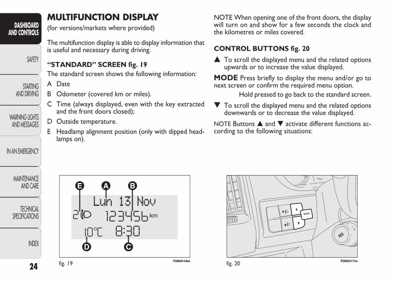
NOTE When opening one of the front doors, the displaywill turn on and show for a few seconds the clock andthe kilometres or miles covered.
CONTROL BUTTONS fig. 20
▲ To scroll the displayed menu and the related optionsupwards or to increase the value displayed.
MODE Press briefly to display the menu and/or go tonext screen or confirm the required menu option.
Hold pressed to go back to the standard screen.
▼ To scroll the displayed menu and the related optionsdownwards or to decrease the value displayed.
NOTE Buttons ▲ and ▼ activate different functions ac-cording to the following situations:
MULTIFUNCTION DISPLAY(for versions/markets where provided)
The multifunction display is able to display information thatis useful and necessary during driving.
“STANDARD” SCREEN fig. 19The standard screen shows the following information:A DateB Odometer (covered km or miles).C Time (always displayed, even with the key extracted
and the front doors closed);D Outside temperature.E Headlamp alignment position (only with dipped head-
lamps on).
24
DASHBOARD AND CONTROLS
SAFETY
STARTING AND DRIVING
WARNING LIGHTSAND MESSAGES
IN AN EMERGENCY
MAINTENANCE AND CARE
TECHNICAL SPECIFICATIONS
INDEX
001-036 DUCATO LUM EN 11-02-2010 13:53 Pagina 24

25
DASHBOARD AND CONTROLS
SAFETY
STARTING AND DRIVING
WARNING LIGHTSAND MESSAGES
IN AN EMERGENCY
MAINTENANCE AND CARE
TECHNICAL SPECIFICATIONS
INDEX
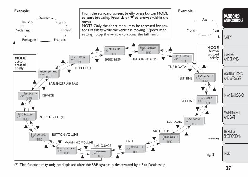
SETUP MENU Fig. 21The menu comprises a series of functions arranged in a cy-cle which can be selected through buttons ▲ and ▼ to ac-cess the different select operations and settings (setup)given in the following paragraphs. A submenu is providedfor some items (Clock and Unit setting).The setup menu can be activated by pressing the MODEbutton briefly.Single presses on buttons ▲ or ▼ will scroll the setup menuoptions.Handling modes are different according to the character-istic of the option selected.
Selection of an option from main menu without submenu:– Briefly press button MODE to select the main menu op-tion that needs to be changed;– Press buttons ▲ or ▼ (by single presses) to select thenew setting;– Briefly press button MODE to store the new setting andat the same time go back to the previously selected menuoption.
Light adjustment inside vehicle
– with the side lights on and standard screen active, it ispossible to adjust the brightness inside the vehicle.
Setup menu
– within the menu, they allow you to scroll up and downthrough the options;– to increase or decrease values during settings.
001-036 DUCATO LUM EN 11-02-2010 13:53 Pagina 25

Prolonged pressing of the button MODE makes it possible:
– to quit the set up menu if you are in the main menu;
– to quit the main menu if you are in another point of themenu (e.g.: at submenu option setting level, at submenulevel or at main menu option setting level);
– to save only the changes stored by the user (and con-firmed by pressing button MODE).
The environment of the Set Up menu is timed; when themenu is exited due to expiry of the time allowed, onlythe changes already stored by the user (confirmed be-forehand by a brief press of the button) will be saved.
Selection of an option from main menu with submenu:
– a short press on the button will display the first submenuoption;
– press buttons ▲ or ▼ (by single presses) to scroll all thesubmenu options;
– briefly press the MODE button to select the displayedsubmenu option and to open the relevant set-up menu;
– press buttons ▲ or ▼ (by single presses) to select thenew setting for this submenu option.
– briefly press button MODE to store the new setting andat the same time go back to the previously selected menuoption.
Selecting “Date” and “Set Clock”:
– briefly press button MODE to select the first value to bechanged (e.g. hours/minutes or year/month/day);
– press buttons ▲ or ▼ (by single presses) to select thenew setting;
– briefly press button MODE to store the new setting andat the same time go to the next setup menu option. If theprocessed option is the last one, the system brings youback to the previously selected option of the main menu.
26
DASHBOARD AND CONTROLS
SAFETY
STARTING AND DRIVING
WARNING LIGHTSAND MESSAGES
IN AN EMERGENCY
MAINTENANCE AND CARE
TECHNICAL SPECIFICATIONS
INDEX
001-036 DUCATO LUM EN 11-02-2010 13:53 Pagina 26
27
DASHBOARD AND CONTROLS
SAFETY
STARTING AND DRIVING
WARNING LIGHTSAND MESSAGES
IN AN EMERGENCY
MAINTENANCE AND CARE
TECHNICAL SPECIFICATIONS
INDEX
Day
Month Year
Deutsch
Français
English
Español
Italiano
Nederland
Português
Example:
fig. 21
Example:From the standard screen, briefly press button MODEto start browsing. Press ▲ or ▼ to browse within themenu.NOTE Only the short menu may be accessed for rea-sons of safety while the vehicle is moving (“Speed Beep”setting). Stop the vehicle to access the full menu.
F0N1000g
MODE button
pressed briefly
▲
▼MENU EXIT
SPEED BEEP HEADLIGHT SENS.
SET TIME
SET DATE
SEE RADIO
AUTOCLOSE
UNITLANGUAGE
WARNING VOLUME
BUTTON VOLUME
BUZZER BELTS (*)
SERVICE
PASSENGER AIR BAG
(*) This function may only be displayed after the SBR system is deactivated by a Fiat Dealership.
TRIP B DATA
MODE button pressed briefly
▲
▼
▲
▼
▲
▼
▲▼
▲▼
▲▼
▲
▼
▲▼
▲ ▼
▲▼
▲
▼
▲
▼ ▲
▼
▼
▲
001-036 DUCATO LUM EN 11-02-2010 13:53 Pagina 27

To cancel the setting, proceed as follows:
– briefly press button MODE: ON flashes on the display;
– press button ▼: OFF flashes on the display;
– press the MODE button briefly to return to the menuscreen or press the button for longer to return to the stan-dard screen without memorizing.
Headlight sensor sensitivity adjustment (for versions/markets where provided)
With this function it is possible to adjust the rain headlightsensitivity according to 3 levels.
To set the required sensitivity level proceed as follows:
– briefly press button MODE: the previously set sensitiv-ity “level” starts flashing on the display;
– press button ▲ or ▼ to adjust;
– press the MODE button briefly to return to the menuscreen or press the button for longer to return to the stan-dard screen without memorizing.
Speed limit (Speed Beep)
This function enables setting of the vehicle speed limit(km/h or mph). When this limit is exceeded the driver isimmediately alerted (see section “Warning lights and mes-sages”).
To set the desired speed limit, proceed as follows:
– briefly press button MODE: the display will show thewording “Speed Beep”;
– press button ▲ or ▼ to select speed limit activation (On)or deactivation (Off);
– if the function has been activated (On), press buttons▲ or ▼ to select the required speed limit and then pressMODE to confirm;
NOTE. The speed may be set in the range from 30 to 200km/h, or from 20 to 125 mph according to the previously cho-sen unit (see “Setting the distance unit” paragraph ) describedbelow. The setting will increase/decrease by five units eachtime button ▲/▼ is pressed. Hold down button ▲/▼ to in-crease/decrease the setting rapidly. Complete the setting bybriefly pressing the button when you approach the requiredsetting.
– press the MODE button briefly to return to the menuscreen or press the button for longer to return to the stan-dard screen without memorizing.
28
DASHBOARD AND CONTROLS
SAFETY
STARTING AND DRIVING
WARNING LIGHTSAND MESSAGES
IN AN EMERGENCY
MAINTENANCE AND CARE
TECHNICAL SPECIFICATIONS
INDEX
001-036 DUCATO LUM EN 11-02-2010 13:53 Pagina 28
29
DASHBOARD AND CONTROLS
SAFETY
STARTING AND DRIVING
WARNING LIGHTSAND MESSAGES
IN AN EMERGENCY
MAINTENANCE AND CARE
TECHNICAL SPECIFICATIONS
INDEX
– when accessing the “Hour” submenu: briefly press buttonMODE: the display shows the “hours” flashing;
– press button ▲ or ▼ to adjust;
– briefly press button MODE: “minutes”starts flashing onthe display;
– press button ▲ or ▼ to adjust;
– when accessing the “Format” submenu: briefly press but-ton MODE : the previously set display format will flashon the display;
– press button ▲ or ▼ to select “24h” or “12h”.
When you have made the required settings, briefly pressthe MODE button to go back to the submenu screen orhold the button down to go back to the main menu screenwithout storing the new settings.
– press the MODE button again for a while to return tothe standard screen or to the main menu according towhere you are in the menu.
Trip B On/Off (tripB data)
This function may be used to activate (On) or deactivate(Off) the Trip B (partial trip).
For further information see the “Trip computer” paragraph.
Proceed as follows to switch the function on and off:
– briefly press button MODE: ON or OFF flashes on thedisplay (according to the previous setting);
– press button ▲ or ▼ to select;
– press the MODE button briefly to return to the menuscreen or press the button for longer to return to the stan-dard screen without memorizing.
Setting the clock (Set time)
This function enables to set the clock through two sub-menus: “Time” and “Format”.
To carry out the adjustment, proceed as follows:
– briefly press the MODE button and two submenus (Timeand Format) are displayed;
– press button ▲ or ▼ to move between the two sub-menus;
– once you have selected a submenu to amend, pressMODE briefly;
001-036 DUCATO LUM EN 11-02-2010 13:53 Pagina 29

Audio repetition (See sound system)With this function the display repeats information relevantto the sound system.– Radio: selected radio station frequency or RDS message,automatic tuning activation or AutoSTore;– audio CD, MP3 CD: track number;– CD Changer: CD number and track number.To show the radio information on the display (On) or clearit (Off), proceed as follows:– briefly press MODE: (On) or (Off) will flash on the dis-play (according to previous setting);
– press button ▲ or ▼ to select;
– press the MODE button briefly to return to the menuscreen or press the button for longer to return to the stan-dard screen without memorizing.
Automatic central door locking with vehicle run-ning (Autoclose)
When activated (On), this function locks automatically thedoors when the vehicle speed exceeds 20 km/h.
To activate (On) or to deactivate (Off) this function pro-ceed as follows:
– briefly press button MODE to display one sub-menu;
– briefly pressMODE button ON or OFF flashes on the dis-play (according to the previous setting);
Set date (Set Date)Using this function it is possible to update the date (day – month – year).Proceed as follows to update:– briefly press button MODE: the day starts flashing on thedisplay (dd);– press button ▲ or ▼ to adjust;– briefly press button MODE: the month starts flashing onthe display (mm);– press button ▲ or ▼ to adjust;– briefly press button MODE: the year starts flashing onthe display (yyyy);
– press button ▲ or ▼ to adjust;
NOTE The setting increases or decreases by one unit eachtime button ▲ or ▼ is pressed. Hold the button pressedto increase/decrease the setting rapidly. Complete the set-ting by briefly pressing the button when you approach therequired setting.– press the MODE button briefly to return to the menuscreen or press the button for longer to return to the stan-dard screen without memorizing.
30
DASHBOARD AND CONTROLS
SAFETY
STARTING AND DRIVING
WARNING LIGHTSAND MESSAGES
IN AN EMERGENCY
MAINTENANCE AND CARE
TECHNICAL SPECIFICATIONS
INDEX
001-036 DUCATO LUM EN 11-02-2010 13:53 Pagina 30
31
DASHBOARD AND CONTROLS
SAFETY
STARTING AND DRIVING
WARNING LIGHTSAND MESSAGES
IN AN EMERGENCY
MAINTENANCE AND CARE
TECHNICAL SPECIFICATIONS
INDEX
– press button ▲ or ▼ to select;
– when accessing the “Consumption” submenu: briefly press but-ton MODE: the display will show “km/l”, “l/100km” or “mpg”(according to previous setting);
If the set distance unit is “km”, the display enables settingof the fuel consumption unit (km/l or l/100) dependingon the amount of fuel consumed.
If the distance unit set is “mi” the fuel consumption unitwill be displayed in “mpg”.
– press button ▲ or ▼ to select;
– when accessing the “Temperature” submenu: briefly press but-ton MODE: the display will show “°C” or “°F” (according toprevious setting);
– press button ▲ or ▼ to select;When you have made the required settings, briefly pressthe MODE button to go back to the submenu screen orhold the button down to go back to the main menu screenwithout storing the new settings. – Press the MODE button again for a while to return tothe standard screen or to the main menu according towhere you are in the menu.
– press button ▲ or ▼ to select;
– press the MODE button briefly to return to the sub-menu screen or give the button a long press to return tothe main menu screen without storing;– press the MODE button again for a while to return tothe standard screen or to the main menu according towhere you are in the menu.
Set units (Unit of measure)
With this function it is possible to set the units throughthree sub-menus: “Distances”, “Consumption” and “Tem-perature”.
To set the required unit proceed as follows:
– briefly press MODE to display the three sub-menus;
– press button ▲ or ▼ to move between the three sub-menus;
– once you have selected a sub-menu, press MODE briefly;
– when accessing the “Distances” submenu: briefly press but-ton MODE: either “km” or “mi” will appear on the display(according to the previous setting);
001-036 DUCATO LUM EN 11-02-2010 13:53 Pagina 31
– press the MODE button briefly to return to the menuscreen or press the button for longer to return to the stan-dard screen without memorizing.
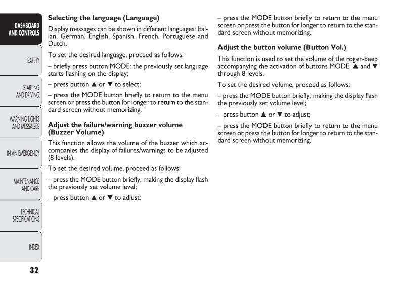
Adjust the button volume (Button Vol.)
This function is used to set the volume of the roger-beepaccompanying the activation of buttons MODE, ▲ and ▼through 8 levels.
To set the desired volume, proceed as follows:
– press the MODE button briefly, making the display flashthe previously set volume level;
– press button ▲ or ▼ to adjust;
– press the MODE button briefly to return to the menuscreen or press the button for longer to return to the stan-dard screen without memorizing.
Selecting the language (Language)
Display messages can be shown in different languages: Ital-ian, German, English, Spanish, French, Portuguese andDutch.
To set the desired language, proceed as follows:
– briefly press button MODE: the previously set languagestarts flashing on the display;
– press button ▲ or ▼ to select;
– press the MODE button briefly to return to the menuscreen or press the button for longer to return to the stan-dard screen without memorizing.
Adjust the failure/warning buzzer volume(Buzzer Volume)
This function allows the volume of the buzzer which ac-companies the display of failures/warnings to be adjusted(8 levels).
To set the desired volume, proceed as follows:
– press the MODE button briefly, making the display flashthe previously set volume level;
– press button ▲ or ▼ to adjust;
32
DASHBOARD AND CONTROLS
SAFETY
STARTING AND DRIVING
WARNING LIGHTSAND MESSAGES
IN AN EMERGENCY
MAINTENANCE AND CARE
TECHNICAL SPECIFICATIONS
INDEX
001-036 DUCATO LUM EN 11-02-2010 13:53 Pagina 32
33
DASHBOARD AND CONTROLS
SAFETY
STARTING AND DRIVING
WARNING LIGHTSAND MESSAGES
IN AN EMERGENCY
MAINTENANCE AND CARE
TECHNICAL SPECIFICATIONS
INDEX
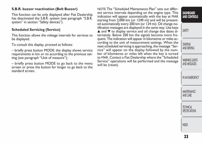
NOTE The “Scheduled Maintenance Plan” sets out differ-ent service intervals depending on the engine type. Thisindication will appear automatically with the key at MARstarting from 2,000 km (or 1240 mi) and will be present-ed automatically every 200 km (or 124 mi). Oil change no-tification messages are displayed in the same way. Use keys▲ and ▼ to display service and oil change due dates al-ternately. Below 200 km the signals become more fre-quent. The indication will appear in kilometres or miles ac-cording to the unit of measurement settings. When thenext scheduled servicing is approaching, the message “Ser-vice” will appear on the display followed by the num-ber of kilometres or miles left when the key is turnedto MAR. Contact a Fiat Dealership where the “ScheduledService” operations will be performed and the messagewill be (reset).
S.B.R. buzzer reactivation (Belt Buzzer)
This function can be only displayed after Fiat Dealershiphas deactivated the S.B.R. system (see paragraph “S.B.R.system” in section “Safety devices”).
Scheduled Servicing (Service)
This function allows the mileage intervals for services tobe displayed.
To consult this display, proceed as follows:
– briefly press button MODE: the display shows servicerequirements in km or mi according to the previous set-ting (see paragraph “Unit of measure”);
– briefly press button MODE to go back to the menuscreen or press the button for longer to go back to thestandard screen.
001-036 DUCATO LUM EN 11-02-2010 13:53 Pagina 33
34
DASHBOARD AND CONTROLS
SAFETY
STARTING AND DRIVING
WARNING LIGHTSAND MESSAGES
IN AN EMERGENCY
MAINTENANCE AND CARE
TECHNICAL SPECIFICATIONS
INDEX
MODE
MODE
MODE
▼▲
▼▲
▼▲
▼▲
F0N1009g
F0N1010g
F0N1011g
F0N1013g
F0N1014g
F0N1009g
F0N1009g
F0N1015g
F0N1016g
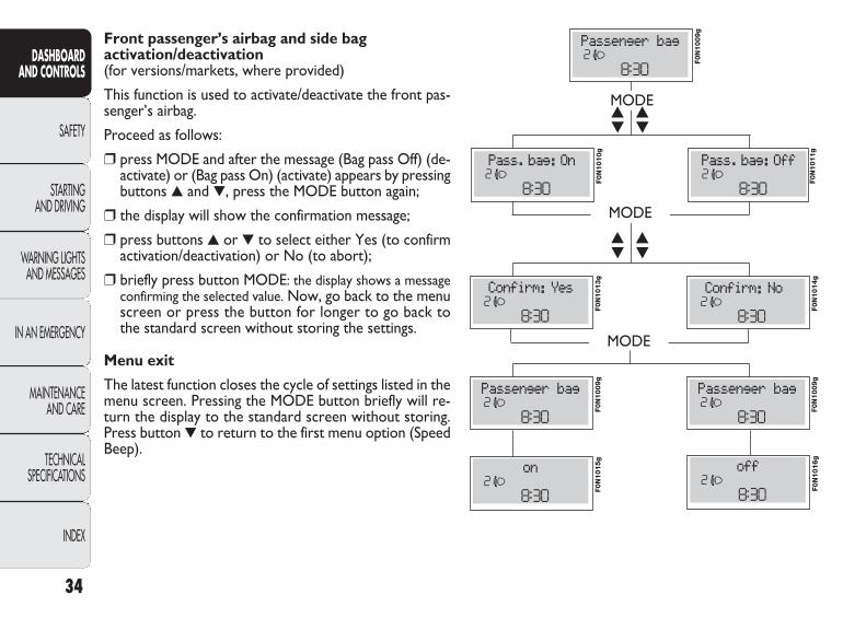
Front passenger’s airbag and side bag activation/deactivation (for versions/markets, where provided)
This function is used to activate/deactivate the front pas-senger’s airbag.
Proceed as follows:
❒ press MODE and after the message (Bag pass Off) (de-activate) or (Bag pass On) (activate) appears by pressingbuttons ▲ and ▼, press the MODE button again;
❒ the display will show the confirmation message;
❒ press buttons ▲ or ▼ to select either Yes (to confirmactivation/deactivation) or No (to abort);
❒ briefly press button MODE: the display shows a messageconfirming the selected value. Now, go back to the menuscreen or press the button for longer to go back tothe standard screen without storing the settings.
Menu exit
The latest function closes the cycle of settings listed in themenu screen. Pressing the MODE button briefly will re-turn the display to the standard screen without storing.Press button ▼ to return to the first menu option (SpeedBeep).
001-036 DUCATO LUM EN 11-02-2010 13:53 Pagina 34
35
DASHBOARD AND CONTROLS
SAFETY
STARTING AND DRIVING
WARNING LIGHTSAND MESSAGES
IN AN EMERGENCY
MAINTENANCE AND CARE
TECHNICAL SPECIFICATIONS
INDEX
Values displayed
External temperature
Indicates the temperature outside the vehicle passengercompartment.
Range (for versions/markets where provided)It indicates the distance left to travel based on the fuel inthe tank assuming that driving conditions will not change.The message “- - -” will appear on the display in the fol-lowing cases:
– range value lower than 50 km (or 30 mi)
– vehicle left parked with engine running for long.
Distance travelled This value shows the distance covered from the start ofthe new mission.
Average consumption (for versions/markets where provided)This value shows the average consumption from the startof the new mission.
Instant consumption (for versions/markets where provided)This indicates the fuel consumption. The value is constantlyupdated. The message “- - -” will appear on the display ifthe vehicle is parked with the engine running.
Average speedRepresents the vehicle average speed as a function of theoverall time elapsed since the start of a new mission.
TRIP COMPUTER
General features
The “Trip computer” is used to display information on ve-hicle operation when the key is turned to MAR. This func-tion allows to define two separate trips called “Trip A”and “Trip B” for monitoring the “complete mission” of thevehicle (trip) in a reciprocally independent manner. Bothfunctions can be zeroed (reset – start of a new journey).
“Trip A” is used to display the figures relating to:– Outside temperature– Range– Trip distance– Average consumption– Instant consumption– Average speed– Travel time (driving time).
“Trip B”, available on multifunction display only, shall beused to display the figures relating to:– Distance travelled B– Average consumption B– Average speed B– Travel time B (driving time).
NOTE “Trip B” function may be excluded (see “Trip B on”).“Range” and “Instantaneous fuel consumption” parame-ters cannot be reset.
001-036 DUCATO LUM EN 11-02-2010 13:53 Pagina 35
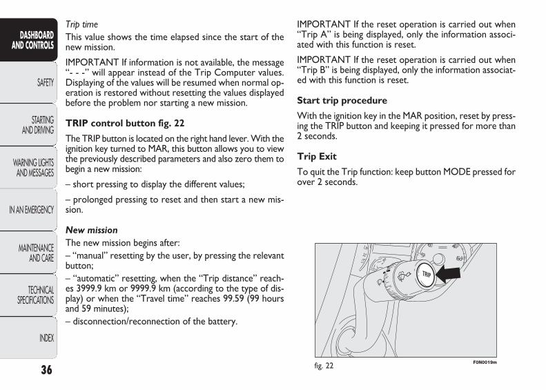
F0N0019mfig. 22
IMPORTANT If the reset operation is carried out when“Trip A” is being displayed, only the information associ-ated with this function is reset.
IMPORTANT If the reset operation is carried out when“Trip B” is being displayed, only the information associat-ed with this function is reset.
Start trip procedure
With the ignition key in the MAR position, reset by press-ing the TRIP button and keeping it pressed for more than2 seconds.
Trip Exit
To quit the Trip function: keep button MODE pressed forover 2 seconds.
Trip timeThis value shows the time elapsed since the start of thenew mission.
IMPORTANT If information is not available, the message“- - -” will appear instead of the Trip Computer values.Displaying of the values will be resumed when normal op-eration is restored without resetting the values displayedbefore the problem nor starting a new mission.
TRIP control button fig. 22
The TRIP button is located on the right hand lever. With theignition key turned to MAR, this button allows you to viewthe previously described parameters and also zero them tobegin a new mission:
– short pressing to display the different values;
– prolonged pressing to reset and then start a new mis-sion.
New mission
The new mission begins after:– “manual” resetting by the user, by pressing the relevantbutton;– “automatic” resetting, when the “Trip distance” reach-es 3999.9 km or 9999.9 km (according to the type of dis-play) or when the “Travel time” reaches 99.59 (99 hoursand 59 minutes);– disconnection/reconnection of the battery.
36
DASHBOARD AND CONTROLS
SAFETY
STARTING AND DRIVING
WARNING LIGHTSAND MESSAGES
IN AN EMERGENCY
MAINTENANCE AND CARE
TECHNICAL SPECIFICATIONS
INDEX
001-036 DUCATO LUM EN 11-02-2010 13:53 Pagina 36
37
DASHBOARD AND CONTROLS
SAFETY
STARTING AND DRIVING
WARNING LIGHTSAND MESSAGES
IN AN EMERGENCY
MAINTENANCE AND CARE
TECHNICAL SPECIFICATIONS
INDEX
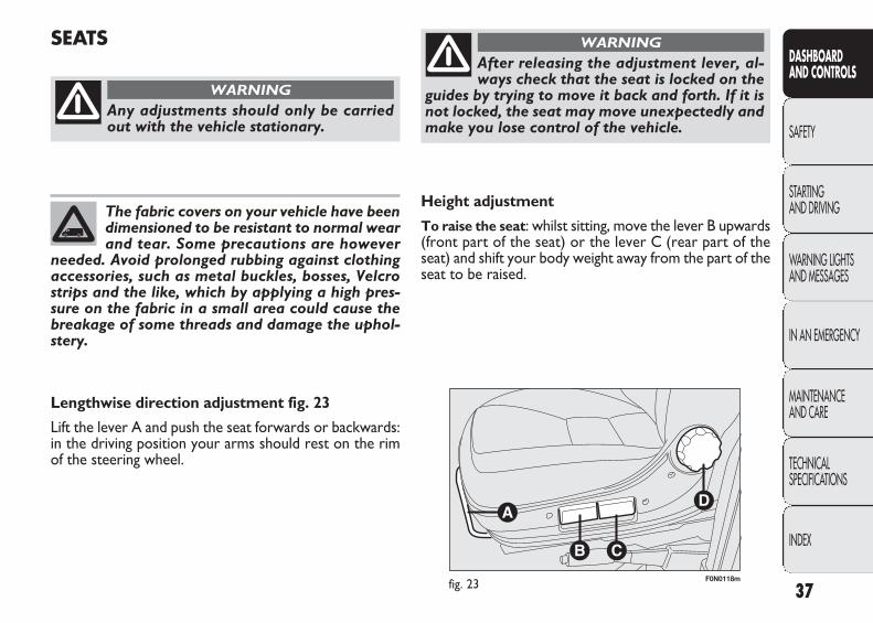
F0N0118mfig. 23
Height adjustment
To raise the seat: whilst sitting, move the lever B upwards(front part of the seat) or the lever C (rear part of theseat) and shift your body weight away from the part of theseat to be raised.
SEATS
Any adjustments should only be carriedout with the vehicle stationary.
WARNING
The fabric covers on your vehicle have beendimensioned to be resistant to normal wearand tear. Some precautions are however
needed. Avoid prolonged rubbing against clothingaccessories, such as metal buckles, bosses, Velcrostrips and the like, which by applying a high pres-sure on the fabric in a small area could cause thebreakage of some threads and damage the uphol-stery.
Lengthwise direction adjustment fig. 23
Lift the lever A and push the seat forwards or backwards:in the driving position your arms should rest on the rimof the steering wheel.
After releasing the adjustment lever, al-ways check that the seat is locked on the
guides by trying to move it back and forth. If it isnot locked, the seat may move unexpectedly andmake you lose control of the vehicle.
WARNING
037-122 DUCATO LUM EN 11-02-2010 14:26 Pagina 37

F0N0147mfig. 24 F0N0139mfig. 25
AIR SEAT
The seat is equipped with a mechanical spring system andhydraulic shock absorber to ensure maximum comfort andsafety. The system of springs also effectively absorbs im-pact from uneven road surfaces.
See the description in the “Front seats” section for thelengthwise adjustments, height adjustments, backrest ad-justment, lumbar adjustment and armrest adjustment.
Damper weight adjustment
Use the adjustment knob A – fig. 25 to set the requiredsetting based on body weight, with settings between 40 kgand 130 kg.
To lower the seat: whilst sitting, move the lever B upwards(front part of the seat) or the lever C (rear part of theseat) and place your body weight on the part of the seatto be lowered.
Backrest angle adjustment fig. 23
Turn knob D.
38
DASHBOARD AND CONTROLS
SAFETY
STARTING AND DRIVING
WARNING LIGHTSAND MESSAGES
IN AN EMERGENCY
MAINTENANCE AND CARE
TECHNICAL SPECIFICATIONS
INDEX
For maximum protection, keep the backof your seat upright, lean back into it and
make sure the seat belt fits closely across yourchest and hips.
WARNING
Lumbar adjustment
To adjust, turn knob E – fig. 24.
037-122 DUCATO LUM EN 11-02-2010 14:26 Pagina 38
39
DASHBOARD AND CONTROLS
SAFETY
STARTING AND DRIVING
WARNING LIGHTSAND MESSAGES
IN AN EMERGENCY
MAINTENANCE AND CARE
TECHNICAL SPECIFICATIONS
INDEX
F0N0148mfig. 26
1 2F0N0187mfig. 27a
F0N0187mfig. 27
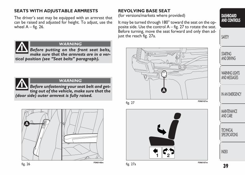
REVOLVING BASE SEAT (for versions/markets where provided)
It may be turned through 180° toward the seat on the op-posite side. Use the control A – fig. 27 to rotate the seat.Before turning, move the seat forward and only then ad-just the reach fig. 27a.
SEATS WITH ADJUSTABLE ARMRESTS
The driver’s seat may be equipped with an armrest thatcan be raised and adjusted for height. To adjust, use thewheel A – fig. 26.
Before putting on the front seat belts,make sure that the armrests are in a ver-
tical position (see “Seat belts” paragraph).
WARNING
Before unfastening your seat belt and get-ting out of the vehicle, make sure that the
(door side) outer armrest is fully raised.
WARNING
037-122 DUCATO LUM EN 11-02-2010 14:26 Pagina 39
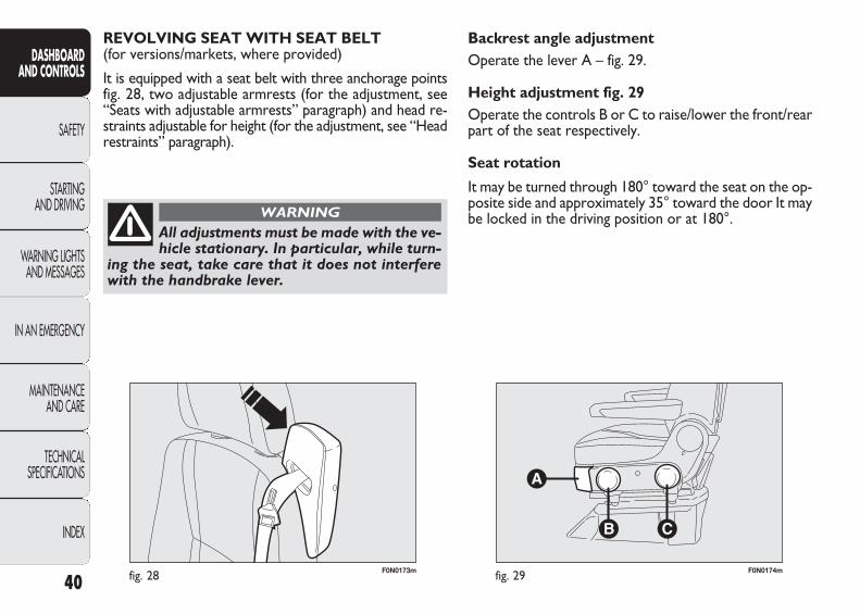
F0N0173mfig. 28 F0N0174mfig. 29
Backrest angle adjustmentOperate the lever A – fig. 29.
Height adjustment fig. 29Operate the controls B or C to raise/lower the front/rearpart of the seat respectively.
Seat rotation
It may be turned through 180° toward the seat on the op-posite side and approximately 35° toward the door It maybe locked in the driving position or at 180°.
REVOLVING SEAT WITH SEAT BELT (for versions/markets, where provided)
It is equipped with a seat belt with three anchorage points fig. 28, two adjustable armrests (for the adjustment, see“Seats with adjustable armrests” paragraph) and head re-straints adjustable for height (for the adjustment, see “Headrestraints” paragraph).
40
DASHBOARD AND CONTROLS
SAFETY
STARTING AND DRIVING
WARNING LIGHTSAND MESSAGES
IN AN EMERGENCY
MAINTENANCE AND CARE
TECHNICAL SPECIFICATIONS
INDEX
All adjustments must be made with the ve-hicle stationary. In particular, while turn-
ing the seat, take care that it does not interferewith the handbrake lever.
WARNING
037-122 DUCATO LUM EN 11-02-2010 14:26 Pagina 40
41
DASHBOARD AND CONTROLS
SAFETY
STARTING AND DRIVING
WARNING LIGHTSAND MESSAGES
IN AN EMERGENCY
MAINTENANCE AND CARE
TECHNICAL SPECIFICATIONS
INDEX
F0N0175mfig. 30a F0N0149mfig. 30c
F0N0213mfig. 30b
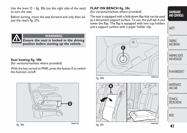
FLAP ON BENCH fig. 30c(for versions/markets where provided)The seat is equipped with a fold-down flap that can be usedas a document support surface. To use, the pull tab A andlower the flap. The flap is equipped with two cup holdersand a support surface with a paper holder clip.
Use the lever D – fig. 30a (on the right side of the seat)to turn the seat.
Before turning, move the seat forward and only then ad-just the reach fig. 27a.
Ensure the seat is locked in the driving position before starting up the vehicle.
WARNING
Seat heating fig. 30b (for versions/markets where provided)
With the key turned to MAR, press the button E to switchthe function on/off.
037-122 DUCATO LUM EN 11-02-2010 14:26 Pagina 41
F0N0237mfig. 30d F0N0238mfig. 30e
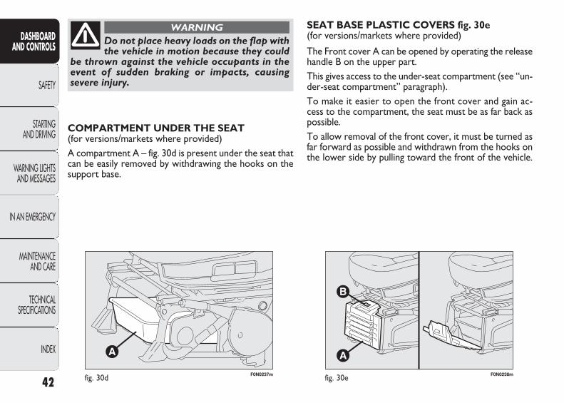
SEAT BASE PLASTIC COVERS fig. 30e(for versions/markets where provided)
The Front cover A can be opened by operating the releasehandle B on the upper part.This gives access to the under-seat compartment (see “un-der-seat compartment” paragraph).To make it easier to open the front cover and gain ac-cess to the compartment, the seat must be as far back aspossible.To allow removal of the front cover, it must be turned asfar forward as possible and withdrawn from the hooks onthe lower side by pulling toward the front of the vehicle.
COMPARTMENT UNDER THE SEAT (for versions/markets where provided)A compartment A – fig. 30d is present under the seat thatcan be easily removed by withdrawing the hooks on thesupport base.
42
DASHBOARD AND CONTROLS
SAFETY
STARTING AND DRIVING
WARNING LIGHTSAND MESSAGES
IN AN EMERGENCY
MAINTENANCE AND CARE
TECHNICAL SPECIFICATIONS
INDEX
Do not place heavy loads on the flap withthe vehicle in motion because they could
be thrown against the vehicle occupants in theevent of sudden braking or impacts, causing severe injury.
WARNING
037-122 DUCATO LUM EN 11-02-2010 14:26 Pagina 42

43
DASHBOARD AND CONTROLS
SAFETY
STARTING AND DRIVING
WARNING LIGHTSAND MESSAGES
IN AN EMERGENCY
MAINTENANCE AND CARE
TECHNICAL SPECIFICATIONS
INDEX
F0N0227mfig. 31 F0N0228mfig. 32
Tilting middle seat backrest (2nd – 3rd row) fig. 31
Lift the lever C and fold the backrest forwards.
A hard surface on the back of the middle seat is used asan armrest and table with cup holders.
Operate the lever to reposition the backrest.
To lower the backrest of the middle seat in the secondrow, remove the head restraint to make it easier to adjustthe backrest of the middle seat in the first row.
COMBI VERSIONS
Easy Entry position
Lift lever A – fig. 32 and tilt the backrest forwards.
PANORAMA VERSIONS
Adjusting the passenger seat tilting backrest fig. 31
Turn the knob A.
Access to seats in second row fig. 31
To gain access to the second row of seats, operate thelever B for the right outer side seat in the first row and tiltthe backrest forward and push with your left hand.
When the seat is restored to its normal position, it engageswith the retaining device without the need to operate thelever again.
On the one-piece Panorama seat in the second row bothside seats are fixed.
037-122 DUCATO LUM EN 11-02-2010 14:26 Pagina 43
F0N0230mfig. 34
F0N0229mfig. 33
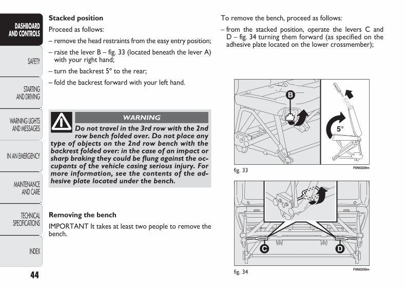
To remove the bench, proceed as follows:
– from the stacked position, operate the levers C and D – fig. 34 turning them forward (as specified on the adhesive plate located on the lower crossmember);
Stacked position
Proceed as follows:
– remove the head restraints from the easy entry position;
– raise the lever B – fig. 33 (located beneath the lever A)with your right hand;
– turn the backrest 5º to the rear;
– fold the backrest forward with your left hand.
44
DASHBOARD AND CONTROLS
SAFETY
STARTING AND DRIVING
WARNING LIGHTSAND MESSAGES
IN AN EMERGENCY
MAINTENANCE AND CARE
TECHNICAL SPECIFICATIONS
INDEX
Do not travel in the 3rd row with the 2ndrow bench folded over. Do not place any
type of objects on the 2nd row bench with thebackrest folded over: in the case of an impact orsharp braking they could be flung against the oc-cupants of the vehicle casing serious injury. Formore information, see the contents of the ad-hesive plate located under the bench.
WARNING
Removing the bench
IMPORTANT It takes at least two people to remove thebench.
037-122 DUCATO LUM EN 11-02-2010 14:26 Pagina 44

45
DASHBOARD AND CONTROLS
SAFETY
STARTING AND DRIVING
WARNING LIGHTSAND MESSAGES
IN AN EMERGENCY
MAINTENANCE AND CARE
TECHNICAL SPECIFICATIONS
INDEX
F0N0231mfig. 35 F0N0020mfig. 36
HEAD RESTRAINTS
FRONT fig. 36
On certain versions the head restraints are adjustable inheight and they lock automatically in the required position.
Adjustment
❒ upwards adjustment: lift the head restraint until it locks;
❒ downward adjustment: press the button A and lowerthe head restraint.
To extract the front head restraints press the buttonsA and B on both sides simultaneously and release themupwards.
– lift the base of the seat forward;
– move the seat upright;
– from the upright position, operate the levers E and F – fig. 35, turning them upward;
– raise the bench from the floor and remove it.
When refitting the bench, ensure it is cor-rectly locked to the floor guides.
WARNING
037-122 DUCATO LUM EN 11-02-2010 14:26 Pagina 45

F0N0321mfig. 37
STEERING WHEEL
The steering wheel position can be adjusted axially.
To carry out the adjustment, proceed as follows:
❒ release the lever fig. 37 pulling it towards the steeringwheel (position 2);
❒ adjust the steering wheel;
❒ lock the lever by pushing it forwards (position 1).
To make the best use of the head restraint protective ac-tion, adjust the seat back so that your trunk is upright andkeep your head as close as possible to the head restraint.
46
DASHBOARD AND CONTROLS
SAFETY
STARTING AND DRIVING
WARNING LIGHTSAND MESSAGES
IN AN EMERGENCY
MAINTENANCE AND CARE
TECHNICAL SPECIFICATIONS
INDEX
Head restraints must be adjusted so thatthe head, rather than the neck, rests on
them. Only then can they protect your head cor-rectly.
WARNING
The adjustments should only be carriedout with the vehicle stationary and the en-
gine turned off.
WARNING
It is absolutely forbidden to carry out anyafter-market operations involving steering
system or steering column modifications (e.g.: in-stallation of anti-theft device). This could affectperformance and safety, invalidate the warrantyand also result in the non-compliance of the ve-hicle with approval requirements.
WARNING
037-122 DUCATO LUM EN 11-02-2010 14:26 Pagina 46

47
DASHBOARD AND CONTROLS
SAFETY
STARTING AND DRIVING
WARNING LIGHTSAND MESSAGES
IN AN EMERGENCY
MAINTENANCE AND CARE
TECHNICAL SPECIFICATIONS
INDEX
F0N0022mfig. 38 F0N0024mfig. 39
Electrical adjustment
This operation is only possible with ignition key in MAR.To adjust the mirror, place the knob B in one of the fourpositions: ÿ1 left mirror, ⁄ 2 right mirror ¤ 3 left wideangle, Ÿ 4 right wide angle.
After positioning the knob, move in the arrowed directionto adjust the glass of the chosen mirror.
MIRRORS
INTERIOR MIRROR fig. 38
The mirror is fitted with a safety device that causes its re-lease in the event of a violent impact with the passenger.
It can be moved using the lever A to two different posi-tions: normal or antiglare.
WING MIRRORS
Adjustment fig. 39
Manual adjustment
Adjust each of the two mirror glasses directly.
The reflective surface of the lower partof the rear view mirror is parabolic and in-
creases the field of view. The image size is reducedand gives the impression that the selected itemis further away than it actually is.
WARNING
037-122 DUCATO LUM EN 11-02-2010 14:26 Pagina 47

F0N0834mfig. 40 F0N0159mfig. 41
IMPORTANT If the mirror is folded back manually, itshould be returned to its original position manually; if themirror is folded back electrically, it should be returnedto its original position electrically.
Defrosting/demisting (for versions/markets where provided)
The mirrors are fitted with resistors that are activatedwhen the heated rear windscreen is turned on (by press-ing button ().
IMPORTANT This function is timed and it will turn off au-tomatically a few minutes later.
Folding
When required (for example when the mirror causes dif-ficulty in narrow spaces) it is possible to fold the mirrormoving it from position 1 – fig. 40 to position 2.
48
DASHBOARD AND CONTROLS
SAFETY
STARTING AND DRIVING
WARNING LIGHTSAND MESSAGES
IN AN EMERGENCY
MAINTENANCE AND CARE
TECHNICAL SPECIFICATIONS
INDEX
When driving the mirrors should always bein position 1 – fig. 40.
Electric folding (for versions/markets where provided)
Adjust the rocker switch A – fig. 41, by pressing on side 1to place the mirror in the open position, on side 2 to placethe mirror in the closed position.
As the driver’s wing mirror is curved, it mayslightly alter the perception of distance.
WARNING
037-122 DUCATO LUM EN 11-02-2010 14:26 Pagina 48
49
DASHBOARD AND CONTROLS
SAFETY
STARTING AND DRIVING
WARNING LIGHTSAND MESSAGES
IN AN EMERGENCY
MAINTENANCE AND CARE
TECHNICAL SPECIFICATIONS
INDEX
fig. 42
F0N0322m
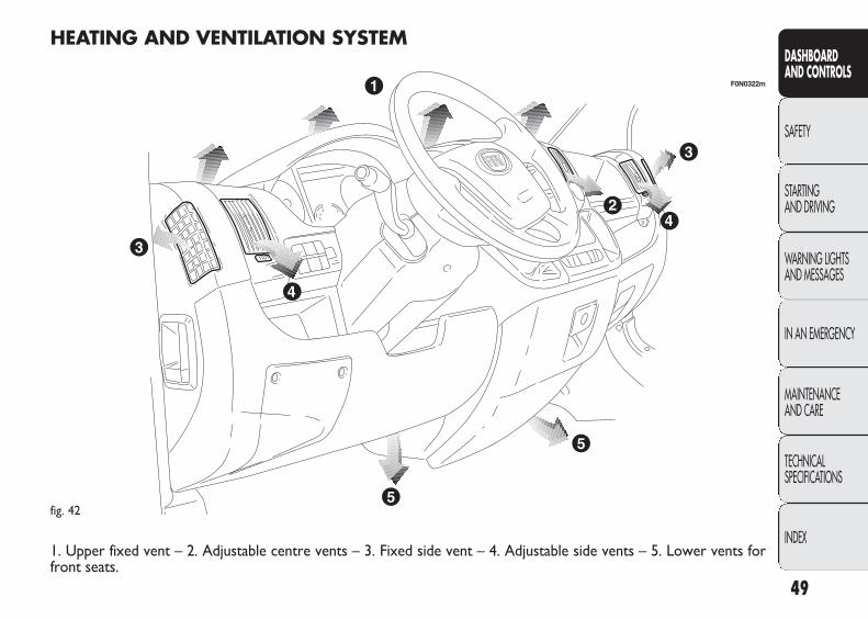
HEATING AND VENTILATION SYSTEM
1. Upper fixed vent – 2. Adjustable centre vents – 3. Fixed side vent – 4. Adjustable side vents – 5. Lower vents forfront seats.
037-122 DUCATO LUM EN 11-02-2010 14:26 Pagina 49
F0N0026mfig. 43
F0N0027mfig. 44 F0N0028mfig. 45
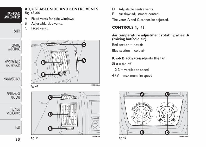
D Adjustable centre vents.E Air flow adjustment control.
The vents A and C cannot be adjusted.
CONTROLS fig. 45
Air temperature adjustment rotating wheel A (mixing hot/cold air)
Red section = hot air
Blue section = cold air
Knob B activates/adjusts the fan
p 0 = fan off
1-2-3 = ventilation speed
4- = maximum fan speed
ADJUSTABLE SIDE AND CENTRE VENTS fig. 43-44
A Fixed vents for side windows.B Adjustable side vents.C Fixed vents.
50
DASHBOARD AND CONTROLS
SAFETY
STARTING AND DRIVING
WARNING LIGHTSAND MESSAGES
IN AN EMERGENCY
MAINTENANCE AND CARE
TECHNICAL SPECIFICATIONS
INDEX
037-122 DUCATO LUM EN 11-02-2010 14:26 Pagina 50
51
DASHBOARD AND CONTROLS
SAFETY
STARTING AND DRIVING
WARNING LIGHTSAND MESSAGES
IN AN EMERGENCY
MAINTENANCE AND CARE
TECHNICAL SPECIFICATIONS
INDEX
PASSENGER COMPARTMENT HEATING
Proceed as follows:
❒ turn the knob A to the red section;
❒ turn the knob C to the required position;
❒ turn the knob B to the required speed.
RAPID PASSENGER COMPARTMENT HEATING
For the rapid heating of the passenger compartment, pro-ceed as follows:
❒ turn the knob A to the red section;
❒ switch on the air recirculation by turning the knob Dto Ò ;
❒ turn the ring nut C to ©;
❒ turn the knob B to 4- (max. fan speed).
Then use the controls to maintain the required comfortconditions and turn the knob D to ⁄ to turn the air re-circulation off and to prevent misting up.
IMPORTANT With cold engine, you have to wait for a fewminutes to let the system fluid reach the operating tem-perature.
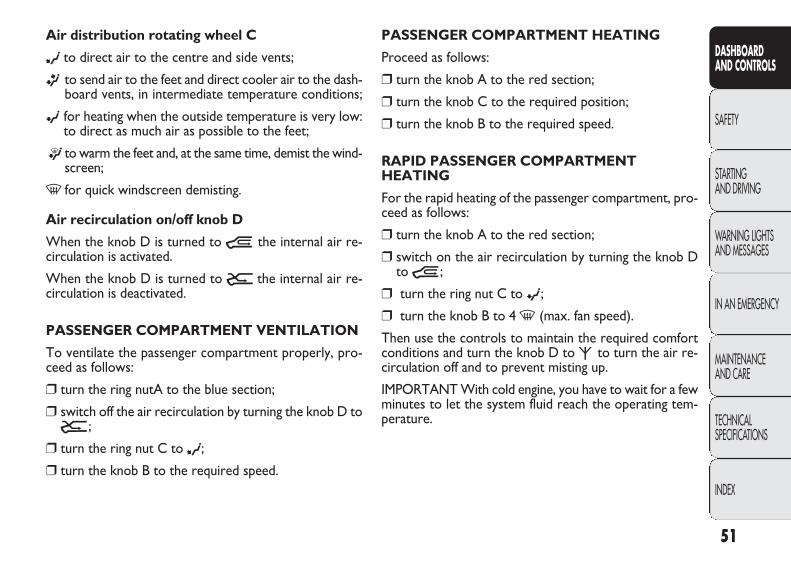
Air distribution rotating wheel C
∂ to direct air to the centre and side vents;
ß to send air to the feet and direct cooler air to the dash-board vents, in intermediate temperature conditions;
© for heating when the outside temperature is very low:to direct as much air as possible to the feet;
® to warm the feet and, at the same time, demist the wind-screen;
- for quick windscreen demisting.
Air recirculation on/off knob D
When the knob D is turned to Ò the internal air re-circulation is activated.
When the knob D is turned to Ú the internal air re-circulation is deactivated.
PASSENGER COMPARTMENT VENTILATION
To ventilate the passenger compartment properly, pro-ceed as follows:
❒ turn the ring nutA to the blue section;
❒ switch off the air recirculation by turning the knob D toÚ ;
❒ turn the ring nut C to ∂;
❒ turn the knob B to the required speed.
037-122 DUCATO LUM EN 11-02-2010 14:26 Pagina 51
52
DASHBOARD AND CONTROLS
SAFETY
STARTING AND DRIVING
WARNING LIGHTSAND MESSAGES
IN AN EMERGENCY
MAINTENANCE AND CARE
TECHNICAL SPECIFICATIONS
INDEX
F0N0185mfig. 46
Window demisting
In the event of considerable external moisture and/or rainand/or large differences in temperature inside and outsidethe passenger compartment, perform the following pre-ventive window demisting procedure:
❒ turn the knob A to the red section;
❒ switch off the air recirculation by turning the knob D toÚ ;
❒ turn the knob C to - or to ® if the windows do notdemist;
❒ turn the knob B to the 2nd speed.
HEATED REAR WINDSCREEN AND DOORMIRRORS DEMISTING/DEFROSTING fig. 47 (for versions/markets where provided)
Press the button A to activate this function; when this func-tion is on the warning light in the button comes on.
This function is timed and will turn off automatically af-ter 20 minutes. Press button A again to switch the func-tion off.
IMPORTANT Do not apply stickers to the inside of therear window over the heating filaments to avoid damagethat might cause it to stop working properly.
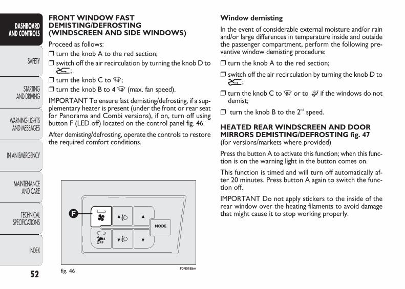
FRONT WINDOW FAST DEMISTING/DEFROSTING (WINDSCREEN AND SIDE WINDOWS)
Proceed as follows:❒ turn the knob A to the red section;❒ switch off the air recirculation by turning the knob D toÚ ;
❒ turn the knob C to -;❒ turn the knob B to 4 - (max. fan speed).
IMPORTANT To ensure fast demisting/defrosting, if a sup-plementary heater is present (under the front or rear seatfor Panorama and Combi versions), if on, turn off usingbutton F (LED off) located on the control panel fig. 46.
After demisting/defrosting, operate the controls to restorethe required comfort conditions.
037-122 DUCATO LUM EN 11-02-2010 14:26 Pagina 52

53
DASHBOARD AND CONTROLS
SAFETY
STARTING AND DRIVING
WARNING LIGHTSAND MESSAGES
IN AN EMERGENCY
MAINTENANCE AND CARE
TECHNICAL SPECIFICATIONS
INDEX
F0N0043mfig. 47
MANUAL CLIMATE CONTROL (for versions/markets where provided)
CONTROLS fig. 48
Air temperature adjustment rotating wheel A (mixing hot/cold air)
Red section = hot air
Blue section = cold air
Knob B activates/adjusts the fan
p 0 = fan off
1-2-3 = ventilation speed
4- = maximum fan speed
INTERNAL air internal recirculation ACTIVATION
Turn the knob D to Ò .
It is advisable to switch the internal air internal recircula-tion on while standing in queues or in tunnels to preventthe introduction of polluted air. Do not use the functionfor a long time, particularly if there are many passengerson board, to prevent the windows from misting up.
IMPORTANT The air recirculation system makes it pos-sible to reach the required heating or cooling conditionsfaster.
Do not use the air recirculation function on rainy/cold daysas it would considerably increase the possibility of the win-dows misting up.
F0N0833mfig. 48
037-122 DUCATO LUM EN 11-02-2010 14:26 Pagina 53

54
DASHBOARD AND CONTROLS
SAFETY
STARTING AND DRIVING
WARNING LIGHTSAND MESSAGES
IN AN EMERGENCY
MAINTENANCE AND CARE
TECHNICAL SPECIFICATIONS
INDEX
Air distribution rotating wheel C
∂ to direct air to the centre and side vents;
ß to send air to the feet and direct cooler air to the dash-board vents, in intermediate temperature conditions;
© for heating when the outside temperature is very low:to direct as much air as possible to the feet;
® to warm the feet and, at the same time, demist thewindscreen;
- for quick windscreen demisting.
Air recirculation on/off knob D
Press the button (button LED on) to turn the air internalrecirculation on.
Press the button again (button LED off) to turn the airinternal recirculation off.
Button E turns climate control system on/off
Press the button (button LED on) to turn the climate con-trol system on.
Press the button again (button LED off) to turn the climatecontrol system off.
PASSENGER COMPARTMENT VENTILATION
To ventilate the passenger compartment properly, proceedas follows:
❒ turn the ring nut A to the blue section;
❒ switch off the air recirculation by turning the knob D toÚ ;
❒ turn the ring nut C to ∂;
❒ turn the knob B to the required speed.
CLIMATE CONTROL (cooling)
For fast cooling of the passenger compartment, proceedas follows:
❒ turn the ring nut A to the blue section;
❒ switch on the air recirculation by turning the knob Dto Ò ;
❒ turn the ring nut C to ∂;
❒ press the button E to turn the climate control systemon; the LED in the button E will come on;
❒ turn the knob B to 4- (max. fan speed).
037-122 DUCATO LUM EN 11-02-2010 14:26 Pagina 54
55
DASHBOARD AND CONTROLS
SAFETY
STARTING AND DRIVING
WARNING LIGHTSAND MESSAGES
IN AN EMERGENCY
MAINTENANCE AND CARE
TECHNICAL SPECIFICATIONS
INDEX
❒ turn the ring nut C to ©;
❒ turn the knob B to 4- (max. fan speed).
Then use the controls to maintain the required comfortconditions and turn the knob D to Ú to turn the air re-circulation off (button LED off).
IMPORTANT With the engine cold you have to wait fora few minutes to let the system fluid reach the optimumoperating temperature.
FRONT WINDOW FAST DEMISTING/DEFROSTING (WINDSCREEN AND SIDE WINDOWS)
Proceed as follows:
❒ turn the knob A to the red section;
❒ turn the knob B to 4- (max. fan speed).
❒ turn the knob C to -;
❒ switch off the air recirculation by turning the knob D toÚ .
Cooling adjustment
❒ turn the knob A to the right to increase the tempera-ture;
❒ switch off the air recirculation by turning the knob D toÚ ;
❒ turn the knob B to reduce the fan speed.
IMPORTANT When the air conditioner compressor but-ton E is pressed, the function is only activated if at leastthe first fan speed is selected (knob B).
PASSENGER COMPARTMENT HEATING
Proceed as follows:
❒ turn the knob A to the red section;
❒ turn the knob C to the required symbol;
❒ turn the knob B to the required speed.
RAPID PASSENGER COMPARTMENT HEATING
For the rapid heating of the passenger compartment, pro-ceed as follows:
❒ turn the knob A to the red section;
❒ turn the air recirculation on by turning the knob D toÒ;
037-122 DUCATO LUM EN 11-02-2010 14:26 Pagina 55
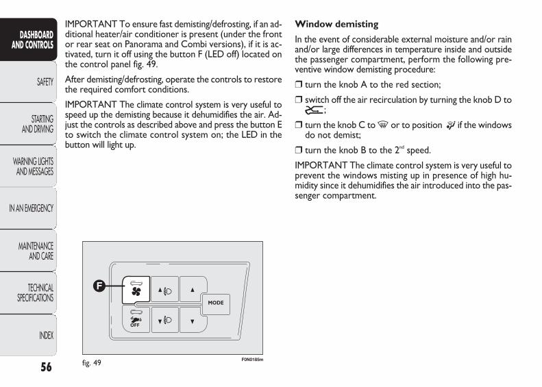
56
DASHBOARD AND CONTROLS
SAFETY
STARTING AND DRIVING
WARNING LIGHTSAND MESSAGES
IN AN EMERGENCY
MAINTENANCE AND CARE
TECHNICAL SPECIFICATIONS
INDEX
F0N0185mfig. 49
Window demisting
In the event of considerable external moisture and/or rainand/or large differences in temperature inside and outsidethe passenger compartment, perform the following pre-ventive window demisting procedure:
❒ turn the knob A to the red section;
❒ switch off the air recirculation by turning the knob D toÚ ;
❒ turn the knob C to - or to position ® if the windowsdo not demist;
❒ turn the knob B to the 2nd speed.
IMPORTANT The climate control system is very useful toprevent the windows misting up in presence of high hu-midity since it dehumidifies the air introduced into the pas-senger compartment.
IMPORTANT To ensure fast demisting/defrosting, if an ad-ditional heater/air conditioner is present (under the frontor rear seat on Panorama and Combi versions), if it is ac-tivated, turn it off using the button F (LED off) located onthe control panel fig. 49.
After demisting/defrosting, operate the controls to restorethe required comfort conditions.
IMPORTANT The climate control system is very useful tospeed up the demisting because it dehumidifies the air. Ad-just the controls as described above and press the button Eto switch the climate control system on; the LED in thebutton will light up.
037-122 DUCATO LUM EN 11-02-2010 14:26 Pagina 56
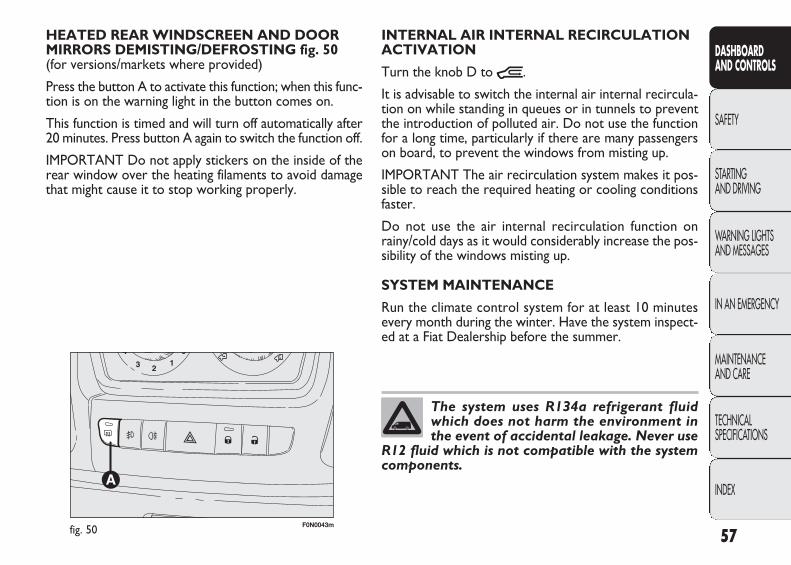
57
DASHBOARD AND CONTROLS
SAFETY
STARTING AND DRIVING
WARNING LIGHTSAND MESSAGES
IN AN EMERGENCY
MAINTENANCE AND CARE
TECHNICAL SPECIFICATIONS
INDEX
F0N0043mfig. 50
INTERNAL AIR INTERNAL RECIRCULATIONACTIVATION
Turn the knob D to Ò.
It is advisable to switch the internal air internal recircula-tion on while standing in queues or in tunnels to preventthe introduction of polluted air. Do not use the functionfor a long time, particularly if there are many passengerson board, to prevent the windows from misting up.
IMPORTANT The air recirculation system makes it pos-sible to reach the required heating or cooling conditionsfaster.
Do not use the air internal recirculation function onrainy/cold days as it would considerably increase the pos-sibility of the windows misting up.
SYSTEM MAINTENANCE
Run the climate control system for at least 10 minutesevery month during the winter. Have the system inspect-ed at a Fiat Dealership before the summer.
HEATED REAR WINDSCREEN AND DOORMIRRORS DEMISTING/DEFROSTING fig. 50 (for versions/markets where provided)
Press the button A to activate this function; when this func-tion is on the warning light in the button comes on.
This function is timed and will turn off automatically after20 minutes. Press button A again to switch the function off.
IMPORTANT Do not apply stickers on the inside of therear window over the heating filaments to avoid damagethat might cause it to stop working properly.
The system uses R134a refrigerant fluidwhich does not harm the environment inthe event of accidental leakage. Never use
R12 fluid which is not compatible with the systemcomponents.
037-122 DUCATO LUM EN 11-02-2010 14:26 Pagina 57
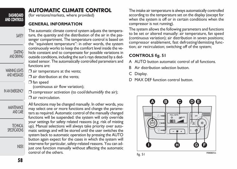
58
DASHBOARD AND CONTROLS
SAFETY
STARTING AND DRIVING
WARNING LIGHTSAND MESSAGES
IN AN EMERGENCY
MAINTENANCE AND CARE
TECHNICAL SPECIFICATIONS
INDEX
The intake air temperature is always automatically controlledaccording to the temperature set on the display (except forwhen the system is off or in certain conditions when thecompressor is not running).The system allows the following parameters and functionsto be set or altered manually: air temperature, fan speed(continuous variation); air distribution in seven positions;compressor enablement, fast defrosting/demisting func-tion; air recirculation; switching off of the system;
CONTROLS fig. 51A AUTO button automatic control of all functions.B Air distribution selection button.C Display. D MAX DEF function control button.
AUTOMATIC CLIMATE CONTROL (for versions/markets, where provided)
GENERAL INFORMATION
The automatic climate control system adjusts the tempera-ture, the quantity and the distribution of the air in the pas-senger compartment. The temperature control is based onthe “equivalent temperature”: in other words, the systemcontinuously works to keep the comfort level inside the ve-hicle constant and to compensate for possible variations inoutside conditions, including the sun’s rays detected by a ded-icated sensor. The automatically controlled parameters andfunctions are:❒ air temperature at the vents;❒ air distribution at the vents;❒ fan speed
(continuous air flow variation);❒ compressor activation (to cool/dehumidify the air);❒ air recirculation.
All functions may be changed manually. In other words, youmay select one or more functions and change the parame-ters as required. Automatic control of the manually changedfunctions will be suspended: the system will only overrideyour settings for safety related reasons (e.g. risk of mistingup). Manual selections will always take priority over auto-matic settings and will be stored until the user switches thesystem back to automatic operation by pressing the AUTObutton again expect for the cases in which the system willintervene for particular, safety-related reasons. You can ad-just one function manually without affecting the automaticcontrol of the others. F0N0831mfig. 51
037-122 DUCATO LUM EN 11-02-2010 14:26 Pagina 58
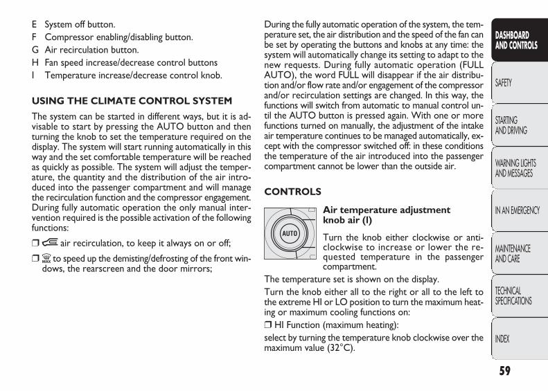
59
DASHBOARD AND CONTROLS
SAFETY
STARTING AND DRIVING
WARNING LIGHTSAND MESSAGES
IN AN EMERGENCY
MAINTENANCE AND CARE
TECHNICAL SPECIFICATIONS
INDEX
E System off button.F Compressor enabling/disabling button.G Air recirculation button.H Fan speed increase/decrease control buttonsI Temperature increase/decrease control knob.
USING THE CLIMATE CONTROL SYSTEM
The system can be started in different ways, but it is ad-visable to start by pressing the AUTO button and thenturning the knob to set the temperature required on thedisplay. The system will start running automatically in thisway and the set comfortable temperature will be reachedas quickly as possible. The system will adjust the temper-ature, the quantity and the distribution of the air intro-duced into the passenger compartment and will managethe recirculation function and the compressor engagement.During fully automatic operation the only manual inter-vention required is the possible activation of the followingfunctions:
❒Ò air recirculation, to keep it always on or off;
❒Z to speed up the demisting/defrosting of the front win-dows, the rearscreen and the door mirrors;
During the fully automatic operation of the system, the tem-perature set, the air distribution and the speed of the fan canbe set by operating the buttons and knobs at any time: thesystem will automatically change its setting to adapt to thenew requests. During fully automatic operation (FULL AUTO), the word FULL will disappear if the air distribu-tion and/or flow rate and/or engagement of the compressorand/or recirculation settings are changed. In this way, thefunctions will switch from automatic to manual control un-til the AUTO button is pressed again. With one or morefunctions turned on manually, the adjustment of the intakeair temperature continues to be managed automatically, ex-cept with the compressor switched off: in these conditionsthe temperature of the air introduced into the passengercompartment cannot be lower than the outside air.
CONTROLS
Air temperature adjustment knob air (l)
Turn the knob either clockwise or anti-clockwise to increase or lower the re-quested temperature in the passengercompartment.
The temperature set is shown on the display.Turn the knob either all to the right or all to the left tothe extreme HI or LO position to turn the maximum heat-ing or maximum cooling functions on:❒ HI Function (maximum heating):select by turning the temperature knob clockwise over themaximum value (32°C).
037-122 DUCATO LUM EN 11-02-2010 14:26 Pagina 59

Air distribution buttons (B)
Press these buttons to manually set one ofthe seven air distribution settings:
▲ Air flow to the windscreen and front side window ventsto demist or defrost them.
˙ Air flow to the centre and side dashboard vents to ven-tilate the chest and the face during the hot season.
▼ Air flow to the front and rear footwell vents. Thanksto the natural tendency of hot air to rise upwards, thisdistribution pattern allows the passenger compartmentto warm up as quickly as possible, providing an imme-diate feeling of warmth.
˙▼
Air flow distribution between footwell vents (hotterair) and centre and side dashboard vents (cooler air).This distribution mode is particularly useful in springand autumn on sunny days.
▲▼
Air flow distributed between the footwell vents andthe windscreen and front side window defrost-ing/demisting vents. This allows an adequate warmingof the passenger compartment and prevents the win-dows from misting up.
This function may be used to heat up the passenger com-partment exploiting the system potential to the maximum.In this condition, the system stops controlling the tem-perature automatically and sets the air mixing to maximumheating. The air speed and distribution are fixed.
In particular, if the heating fluid is not sufficiently hot, themaximum fan speed does not come on straight away inorder to limit the intake of insufficiently hot air into thepassenger compartment.
All manual settings will be allowed when this function is on.
To switch the function off, simply turn the temperatureknob anticlockwise and set the required temperature.
❒ LO function (maximum cooling):
select by turning the temperature knob anticlockwise un-der the minimum value (16°C).
This function may be used to cool down the passengercompartment exploiting the system potential to the max-imum. In this condition, the system stops controlling thetemperature automatically and sets the air mixing to max-imum cooling. The air speed and distribution are fixed. Allmanual settings will be allowed when this function is on.
To switch the function off, simply turn the temperatureknob anticlockwise and set the required temperature.
60
DASHBOARD AND CONTROLS
SAFETY
STARTING AND DRIVING
WARNING LIGHTSAND MESSAGES
IN AN EMERGENCY
MAINTENANCE AND CARE
TECHNICAL SPECIFICATIONS
INDEX
037-122 DUCATO LUM EN 11-02-2010 14:26 Pagina 60
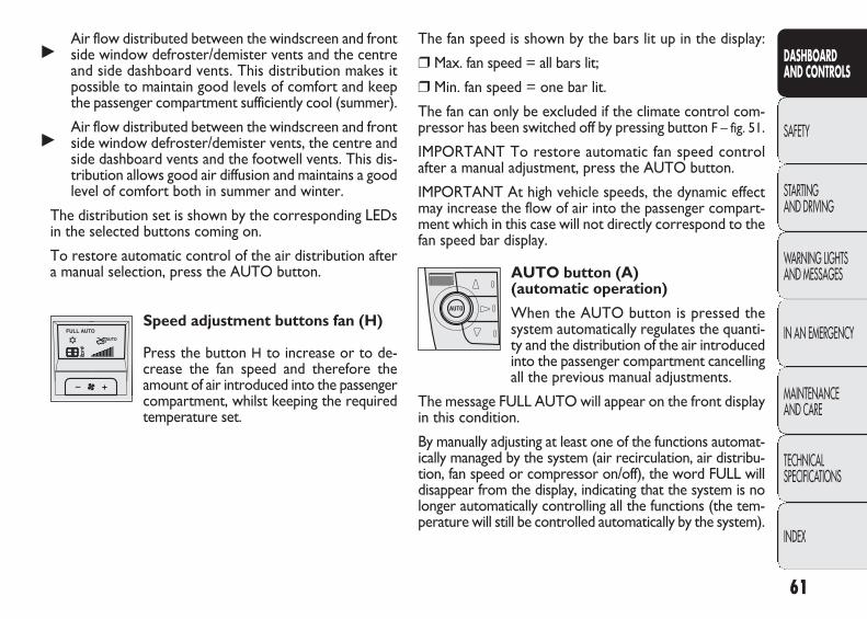
61
DASHBOARD AND CONTROLS
SAFETY
STARTING AND DRIVING
WARNING LIGHTSAND MESSAGES
IN AN EMERGENCY
MAINTENANCE AND CARE
TECHNICAL SPECIFICATIONS
INDEX
The fan speed is shown by the bars lit up in the display:
❒ Max. fan speed = all bars lit;
❒ Min. fan speed = one bar lit.
The fan can only be excluded if the climate control com-pressor has been switched off by pressing button F – fig. 51.
IMPORTANT To restore automatic fan speed control after a manual adjustment, press the AUTO button.
IMPORTANT At high vehicle speeds, the dynamic effectmay increase the flow of air into the passenger compart-ment which in this case will not directly correspond to thefan speed bar display.
AUTO button (A)(automatic operation)
When the AUTO button is pressed thesystem automatically regulates the quanti-ty and the distribution of the air introducedinto the passenger compartment cancellingall the previous manual adjustments.
The message FULL AUTO will appear on the front displayin this condition.
By manually adjusting at least one of the functions automat-ically managed by the system (air recirculation, air distribu-tion, fan speed or compressor on/off), the word FULL willdisappear from the display, indicating that the system is nolonger automatically controlling all the functions (the tem-perature will still be controlled automatically by the system).
˙Air flow distributed between the windscreen and frontside window defroster/demister vents and the centreand side dashboard vents. This distribution makes itpossible to maintain good levels of comfort and keepthe passenger compartment sufficiently cool (summer).
˙Air flow distributed between the windscreen and frontside window defroster/demister vents, the centre andside dashboard vents and the footwell vents. This dis-tribution allows good air diffusion and maintains a goodlevel of comfort both in summer and winter.
The distribution set is shown by the corresponding LEDsin the selected buttons coming on.
To restore automatic control of the air distribution aftera manual selection, press the AUTO button.
Speed adjustment buttons fan (H)
Press the button H to increase or to de-crease the fan speed and therefore theamount of air introduced into the passengercompartment, whilst keeping the requiredtemperature set.
037-122 DUCATO LUM EN 11-02-2010 14:26 Pagina 61

It is however inadvisable to use it on rainy/cold days as itwould considerably increase the possibility of the windowsmisting up, especially if the climate control compressor isoff.
The recirculation is forced off (i.e. air is introduced fromthe outside) when the the outside temperature is cold toprevent misting up.
It is advisable not to use the air recirculation function whenthe outside temperature is low to prevent the windowsfrom rapidly misting up.
Climate control compressor enabling/disabling button (F)
Pressing the √ button switches the climatecontrol compressor off, it if was on previ-ously and the logo in the display goes out.
Press the button when the LED is off to automatically re-store system control and use of the compressor. The iconwill light up in the display in this case.
The system will switch the recirculation off when the com-pressor is switched off to prevent the windows misting up.Although the system is capable of maintaining the requiredtemperature, the word FULL will disappear from the display.If the system is no longer able to maintain the temperature,the figures will flash and the message AUTO will go off.
IMPORTANT Should the system (after manual settings)no longer be able to guarantee the required temperatureset in the passenger compartment, the set temperaturevalue will start flashing to indicate the difficulties the sys-tem is experiencing and then the word AUTO will go out.
To restore system automatic control at any time, after oneor more manual adjustments, press the AUTO button.
Air recirculation on/off button (G)
The Air recirculation works according tothe following operating logics:
❒ override on (air recirculation always on), indicated bythe LED in button G being on and symbol í in the dis-play;
❒ override off (air recirculation always off and introduc-tion of outside air), indicated by the fact that the LEDin the button goes off and symbol êwill appear on thedisplay.
These operating conditions are obtained by pressing airrecirculation button G in sequence.
IMPORTANT The engagement of the air recirculation sys-tem makes it possible to reach the required heating orcooling conditions faster.
62
DASHBOARD AND CONTROLS
SAFETY
STARTING AND DRIVING
WARNING LIGHTSAND MESSAGES
IN AN EMERGENCY
MAINTENANCE AND CARE
TECHNICAL SPECIFICATIONS
INDEX
037-122 DUCATO LUM EN 11-02-2010 14:26 Pagina 62
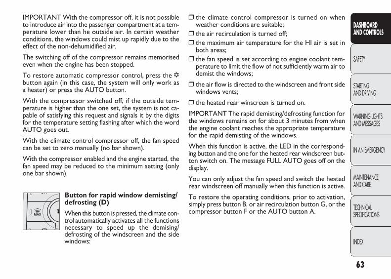
63
DASHBOARD AND CONTROLS
SAFETY
STARTING AND DRIVING
WARNING LIGHTSAND MESSAGES
IN AN EMERGENCY
MAINTENANCE AND CARE
TECHNICAL SPECIFICATIONS
INDEX
IMPORTANT With the compressor off, it is not possibleto introduce air into the passenger compartment at a tem-perature lower than he outside air. In certain weatherconditions, the windows could mist up rapidly due to theeffect of the non-dehumidified air.
The switching off of the compressor remains memorisedeven when the engine has been stopped.
To restore automatic compressor control, press the √button again (in this case, the system will only work as a heater) or press the AUTO button.
With the compressor switched off, if the outside tem-perature is higher than the one set, the system is not ca-pable of satisfying this request and signals it by the digitsfor the temperature setting flashing after which the wordAUTO goes out.
With the climate control compressor off, the fan speedcan be set to zero manually (no bar shown).
With the compressor enabled and the engine started, thefan speed may be reduced to the minimum setting (onlyone bar shown).
Button for rapid window demisting/defrosting (D)
When this button is pressed, the climate con-trol automatically activates all the functions necessary to speed up the demising/ defrosting of the windscreen and the sidewindows:
❒ the climate control compressor is turned on whenweather conditions are suitable;
❒ the air recirculation is turned off;❒ the maximum air temperature for the HI air is set in
both areas;❒ the fan speed is set according to engine coolant tem-
perature to limit the flow of not sufficiently warm air todemist the windows;
❒ the air flow is directed to the windscreen and front sidewindows vents;
❒ the heated rear winscreen is turned on.
IMPORTANT The rapid demisting/defrosting function forthe windows remains on for about 3 minutes from whenthe engine coolant reaches the appropriate temperaturefor the rapid demisting of the windows.
When this function is active, the LED in the correspond-ing button and the one for the heated rear windscreen but-ton switch on. The message FULL AUTO goes off on thedisplay.
You can only adjust the fan speed and switch the heatedrear windscreen off manually when this function is active.
To restore the operating conditions, prior to activation,simply press button B, or air recirculation button G, or thecompressor button F or the AUTO button A.
037-122 DUCATO LUM EN 11-02-2010 14:26 Pagina 63

F0N0185mfig. 52
IMPORTANT To ensure rapid demisting/defrosting, ifthere is an additional heater/air conditioner (under thefront or rear seat on Panorama and Combi versions), if ac-tivated, deactivate it by pressing button F (LED off) locat-ed on the control panel fig. 52.
Switching the system OFF (E)
The climate control system is switched offby pressing button E and the display goesout as a result.
With the system off, the climate control system conditionsare as follows: display off, temperature setting not dis-play, air recirculation on thereby insulating the passengercompartment from the outside (recirculation LED on), cli-mate control compressor off, fan off. Press the AUTO but-ton to switch the the climate control system back on inautomatic mode.
64
DASHBOARD AND CONTROLS
SAFETY
STARTING AND DRIVING
WARNING LIGHTSAND MESSAGES
IN AN EMERGENCY
MAINTENANCE AND CARE
TECHNICAL SPECIFICATIONS
INDEX
F0N0185mfig. 53
ADDITIONAL HEATER (for versions/markets where provided)
On some versions, an additional heater is also present be-neath the driver’s seat. The fan for this heater is operat-ed by means of the button F located on the control panelfig. 53.
037-122 DUCATO LUM EN 11-02-2010 14:26 Pagina 64

65
DASHBOARD AND CONTROLS
SAFETY
STARTING AND DRIVING
WARNING LIGHTSAND MESSAGES
IN AN EMERGENCY
MAINTENANCE AND CARE
TECHNICAL SPECIFICATIONS
INDEX
INDEPENDENT ADDITIONAL HEATER (for versions/markets where provided)
The vehicle is available, on request, with two different in-dependent heaters: one fully automatic, the other whichcan be programmed.
AUTOMATIC VERSION
The additional heater is turned on in automatic mode whenthe engine is started and the required outside tempera-ture and coolant conditions are present. Deactivation isalways automatic.
IMPORTANT During periods with low outdoor temper-atures when the device cuts in, check that the fuel levelis always higher than the reserve level. Otherwise the de-vice could lock and require the assistance of a Fiat Deal-ership.
The heater burns fuel in the same way asthe engine, though to a lesser extent. To
prevent poisoning and asphyxiation, the supple-mentary heater must never be turned on, even forshort periods, in closed environments such as agarage or workshops without extraction fans forthe exhaust gases.
WARNING
PROGRAMMABLE VERSION
The additional heater operates completely independentlyof engine operation and allows the following:
❒ heating the vehicle passenger compartment with the en-gine off;
❒ defrosting the windows;
❒ heating the engine coolant and consequently the actu-al engine prior to starting.
The system consists of:
❒ a diesel burner to heat the water with an exhaust si-lencer for the combustion gases;
❒ a metering pump connected to the vehicle tank pipes,to supply the burner;
❒ a heat exchanger connected to the engine cooling sys-tem pipes;
❒ a control unit connected to the passenger compartmentheating/ventilation system to allow automatic operation;
❒ an electronic control unit for control and operation ofthe burner in the heater;
❒ a digital timer A-fig. 54 for turning the heater on man-ually or programming the time it comes on.
037-122 DUCATO LUM EN 11-02-2010 14:26 Pagina 65

F0N0150mfig. 54
(In winter) the additional heater provides heat, maintainsthe temperature and circulates the engine coolant for thepreset time in order to ensure the optimum temperatureconditions of the engine and the passenger compartmentwhen the engine is started up.
The heater can operate automatically when programmedwith a digital timer or manually by pressing the ‘immedi-ate heating’ button on the timer.
After heater activation, either programmed or manual, theelectronic control unit operates the liquid circulation pumpand ignites the burner in accordance with the preset, con-trolled procedures.
The circulation pump output is also controlled by the elec-tronic control unit in order to minimise the initial heat-ing time.
66
DASHBOARD AND CONTROLS
SAFETY
STARTING AND DRIVING
WARNING LIGHTSAND MESSAGES
IN AN EMERGENCY
MAINTENANCE AND CARE
TECHNICAL SPECIFICATIONS
INDEX
When the system operates, the control unit turns on thepassenger compartment heater unit fan at the secondspeed.
The thermal power of the boiler is regulated automaticallyby the electronic control unit depending on the temper-ature of the engine coolant.
IMPORTANT If heater is equipped with a thermal limiterthat cuts off combustion in the case of overheating dueto insufficient coolant/coolant leaks. In this case, after re-pairing the fault in the cooling system and/or topping upthe fluid, press the program selection button before turn-ing the heater back on.
The heater can turn off spontaneously due to misfiringafter start-up or because the flame goes out during oper-ation. In this case, carry out the turning off procedureand try to turn the heater back on. If it still does not work,consult a Fiat Dealership.
Activation of the heating system
When an automatic climate control system is present, thecontrol unit sets the air temperature and distribution whenthe heater is turned on from the park position. When a manual heater/climate control is present, to obtain max-imum heater efficiency, check that the passenger com-partment heating/ventilation temperature adjustment knobis in the ‘hot air’ position.
To prioritise passenger compartment pre-heating, set theair distribution knob to the © position.
037-122 DUCATO LUM EN 11-02-2010 14:26 Pagina 66
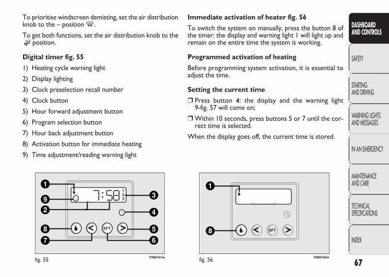
67
DASHBOARD AND CONTROLS
SAFETY
STARTING AND DRIVING
WARNING LIGHTSAND MESSAGES
IN AN EMERGENCY
MAINTENANCE AND CARE
TECHNICAL SPECIFICATIONS
INDEX
F0N0151mfig. 55
To prioritise windscreen demisting, set the air distributionknob to the – position -.
To get both functions, set the air distribution knob to the® position.
Digital timer fig. 55
1) Heating cycle warning light
2) Display lighting
3) Clock preselection recall number
4) Clock button
5) Hour forward adjustment button
6) Program selection button
7) Hour back adjustment button
8) Activation button for immediate heating
9) Time adjustment/reading warning light
F0N0152mfig. 56
Immediate activation of heater fig. 56
To switch the system on manually, press the button 8 ofthe timer: the display and warning light 1 will light up andremain on the entire time the system is working.
Programmed activation of heating
Before programming system activation, it is essential toadjust the time.
Setting the current time
❒ Press button 4: the display and the warning light 9-fig. 57 will come on;
❒ Within 10 seconds, press buttons 5 or 7 until the cor-rect time is selected.
When the display goes off, the current time is stored.
037-122 DUCATO LUM EN 11-02-2010 14:26 Pagina 67
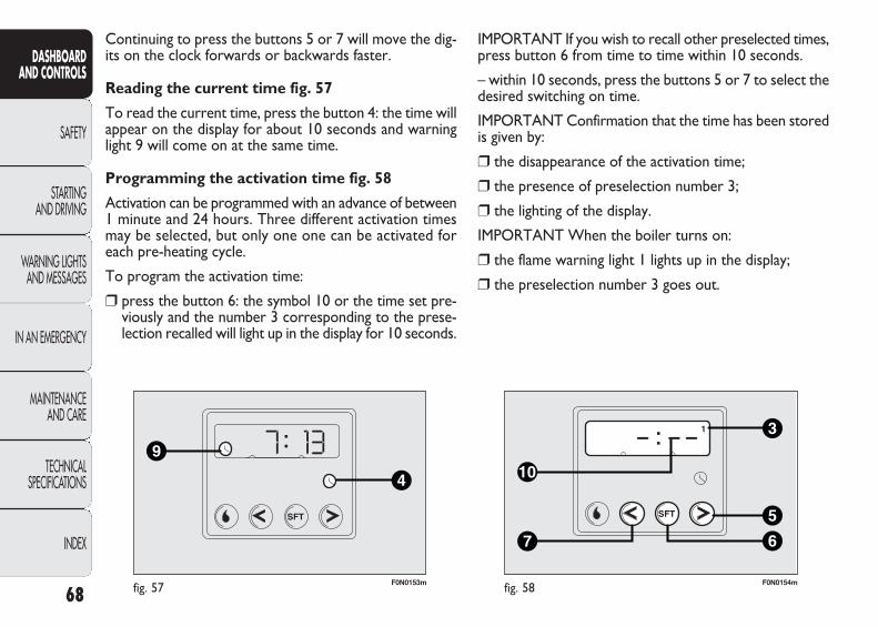
F0N0153mfig. 57
Continuing to press the buttons 5 or 7 will move the dig-its on the clock forwards or backwards faster.
Reading the current time fig. 57
To read the current time, press the button 4: the time willappear on the display for about 10 seconds and warninglight 9 will come on at the same time.
Programming the activation time fig. 58
Activation can be programmed with an advance of between1 minute and 24 hours. Three different activation timesmay be selected, but only one one can be activated foreach pre-heating cycle.
To program the activation time:
❒ press the button 6: the symbol 10 or the time set pre-viously and the number 3 corresponding to the prese-lection recalled will light up in the display for 10 seconds.
68
DASHBOARD AND CONTROLS
SAFETY
STARTING AND DRIVING
WARNING LIGHTSAND MESSAGES
IN AN EMERGENCY
MAINTENANCE AND CARE
TECHNICAL SPECIFICATIONS
INDEX
F0N0154mfig. 58
IMPORTANT If you wish to recall other preselected times,press button 6 from time to time within 10 seconds.
– within 10 seconds, press the buttons 5 or 7 to select thedesired switching on time.
IMPORTANT Confirmation that the time has been storedis given by:
❒ the disappearance of the activation time;
❒ the presence of preselection number 3;
❒ the lighting of the display.
IMPORTANT When the boiler turns on:
❒ the flame warning light 1 lights up in the display;
❒ the preselection number 3 goes out.
037-122 DUCATO LUM EN 11-02-2010 14:26 Pagina 68
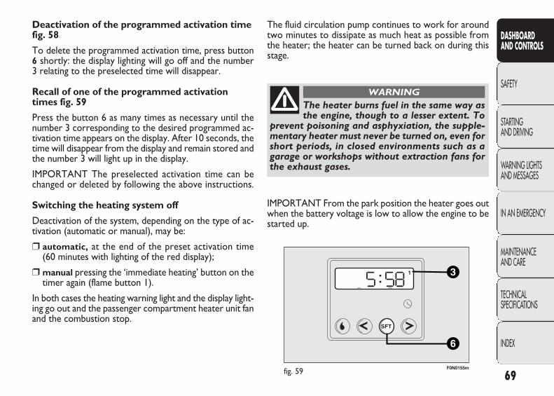
69
DASHBOARD AND CONTROLS
SAFETY
STARTING AND DRIVING
WARNING LIGHTSAND MESSAGES
IN AN EMERGENCY
MAINTENANCE AND CARE
TECHNICAL SPECIFICATIONS
INDEX
Deactivation of the programmed activation timefig. 58
To delete the programmed activation time, press button6 shortly: the display lighting will go off and the number 3 relating to the preselected time will disappear.
Recall of one of the programmed activationtimes fig. 59
Press the button 6 as many times as necessary until thenumber 3 corresponding to the desired programmed ac-tivation time appears on the display. After 10 seconds, thetime will disappear from the display and remain stored andthe number 3 will light up in the display.
IMPORTANT The preselected activation time can bechanged or deleted by following the above instructions.
Switching the heating system off
Deactivation of the system, depending on the type of ac-tivation (automatic or manual), may be:
❒ automatic, at the end of the preset activation time (60 minutes with lighting of the red display);
❒ manual pressing the ‘immediate heating’ button on thetimer again (flame button 1).
In both cases the heating warning light and the display light-ing go out and the passenger compartment heater unit fanand the combustion stop.
F0N0155mfig. 59
The fluid circulation pump continues to work for aroundtwo minutes to dissipate as much heat as possible fromthe heater; the heater can be turned back on during thisstage.
The heater burns fuel in the same way asthe engine, though to a lesser extent. To
prevent poisoning and asphyxiation, the supple-mentary heater must never be turned on, even forshort periods, in closed environments such as agarage or workshops without extraction fans forthe exhaust gases.
WARNING
IMPORTANT From the park position the heater goes outwhen the battery voltage is low to allow the engine to bestarted up.
037-122 DUCATO LUM EN 11-02-2010 14:26 Pagina 69
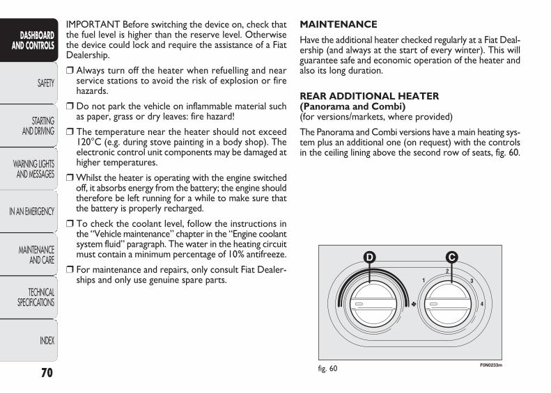
IMPORTANT Before switching the device on, check thatthe fuel level is higher than the reserve level. Otherwisethe device could lock and require the assistance of a FiatDealership.
❒ Always turn off the heater when refuelling and nearservice stations to avoid the risk of explosion or firehazards.
❒ Do not park the vehicle on inflammable material suchas paper, grass or dry leaves: fire hazard!
❒ The temperature near the heater should not exceed120°C (e.g. during stove painting in a body shop). Theelectronic control unit components may be damaged athigher temperatures.
❒ Whilst the heater is operating with the engine switchedoff, it absorbs energy from the battery; the engine shouldtherefore be left running for a while to make sure thatthe battery is properly recharged.
❒ To check the coolant level, follow the instructions inthe “Vehicle maintenance” chapter in the “Engine coolantsystem fluid” paragraph. The water in the heating circuitmust contain a minimum percentage of 10% antifreeze.
❒ For maintenance and repairs, only consult Fiat Dealer-ships and only use genuine spare parts.
70
DASHBOARD AND CONTROLS
SAFETY
STARTING AND DRIVING
WARNING LIGHTSAND MESSAGES
IN AN EMERGENCY
MAINTENANCE AND CARE
TECHNICAL SPECIFICATIONS
INDEX
F0N0233mfig. 60
MAINTENANCE
Have the additional heater checked regularly at a Fiat Deal-ership (and always at the start of every winter). This willguarantee safe and economic operation of the heater andalso its long duration.
REAR ADDITIONAL HEATER (Panorama and Combi) (for versions/markets, where provided)
The Panorama and Combi versions have a main heating sys-tem plus an additional one (on request) with the controlsin the ceiling lining above the second row of seats, fig. 60.
037-122 DUCATO LUM EN 11-02-2010 14:26 Pagina 70
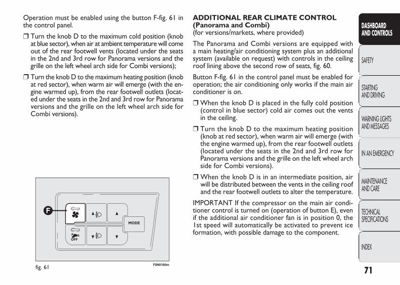
71
DASHBOARD AND CONTROLS
SAFETY
STARTING AND DRIVING
WARNING LIGHTSAND MESSAGES
IN AN EMERGENCY
MAINTENANCE AND CARE
TECHNICAL SPECIFICATIONS
INDEX
Operation must be enabled using the button F-fig. 61 inthe control panel.
❒ Turn the knob D to the maximum cold position (knobat blue sector), when air at ambient temperature will comeout of the rear footwell vents (located under the seatsin the 2nd and 3rd row for Panorama versions and thegrille on the left wheel arch side for Combi versions);
❒ Turn the knob D to the maximum heating position (knobat red sector), when warm air will emerge (with the en-gine warmed up), from the rear footwell outlets (locat-ed under the seats in the 2nd and 3rd row for Panoramaversions and the grille on the left wheel arch side forCombi versions).
F0N0185mfig. 61
ADDITIONAL REAR CLIMATE CONTROL (Panorama and Combi) (for versions/markets, where provided)
The Panorama and Combi versions are equipped with a main heating/air conditioning system plus an additionalsystem (available on request) with controls in the ceilingroof lining above the second row of seats, fig. 60.
Button F-fig. 61 in the control panel must be enabled foroperation; the air conditioning only works if the main airconditioner is on.
❒ When the knob D is placed in the fully cold position(control in blue sector) cold air comes out the ventsin the ceiling.
❒ Turn the knob D to the maximum heating position(knob at red sector), when warm air will emerge (withthe engine warmed up), from the rear footwell outlets(located under the seats in the 2nd and 3rd row forPanorama versions and the grille on the left wheel archside for Combi versions).
❒ When the knob D is in an intermediate position, airwill be distributed between the vents in the ceiling roofand the rear footwell outlets to alter the temperature.
IMPORTANT If the compressor on the main air condi-tioner control is turned on (operation of button E), evenif the additional air conditioner fan is in position 0, the1st speed will automatically be activated to prevent iceformation, with possible damage to the component.
037-122 DUCATO LUM EN 11-02-2010 14:26 Pagina 71
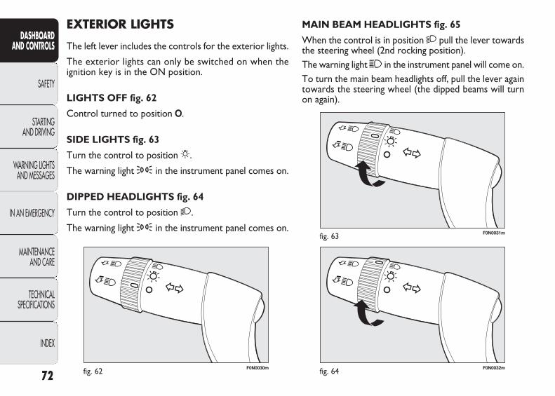
F0N0030mfig. 62 F0N0032mfig. 64
F0N0031mfig. 63
MAIN BEAM HEADLIGHTS fig. 65
When the control is in position 2 pull the lever towardsthe steering wheel (2nd rocking position).The warning light 1 in the instrument panel will come on.To turn the main beam headlights off, pull the lever againtowards the steering wheel (the dipped beams will turnon again).
EXTERIOR LIGHTS
The left lever includes the controls for the exterior lights.
The exterior lights can only be switched on when theignition key is in the ON position.
LIGHTS OFF fig. 62
Control turned to position O.
SIDE LIGHTS fig. 63
Turn the control to position 6.
The warning light 3 in the instrument panel comes on.
DIPPED HEADLIGHTS fig. 64
Turn the control to position 2.
The warning light 3 in the instrument panel comes on.
72
DASHBOARD AND CONTROLS
SAFETY
STARTING AND DRIVING
WARNING LIGHTSAND MESSAGES
IN AN EMERGENCY
MAINTENANCE AND CARE
TECHNICAL SPECIFICATIONS
INDEX
037-122 DUCATO LUM EN 11-02-2010 14:26 Pagina 72

F0N0033mfig. 65
F0N0034mfig. 66
Warning light F or D start flashing in the instrumentpanel.
Direction indicators are switched off automatically whenthe steering wheel of the vehicle is straightened.
FLASHING fig. 66
Pull the lever towards the steering wheel (1st rocking po-sition) regardless of the position of the control. The warn-ing light 1 in the instrument panel will come on.
PARKING LIGHTS
These lights can only be turned on with ignition key inthe STOP position or removed, by moving the left levercontrol first to O and then to 6 or 2.
The warning light 3 in the instrument panel comes on.
DIRECTION INDICATORS fig. 67
Put the stalk in the permanent position:
❒ up (position 1): activation of right direction indicator;
❒ down (position 2): activation of left direction indicator.
73
DASHBOARD AND CONTROLS
SAFETY
STARTING AND DRIVING
WARNING LIGHTSAND MESSAGES
IN AN EMERGENCY
MAINTENANCE AND CARE
TECHNICAL SPECIFICATIONS
INDEX
F0N0035mfig. 67
037-122 DUCATO LUM EN 11-02-2010 14:26 Pagina 73
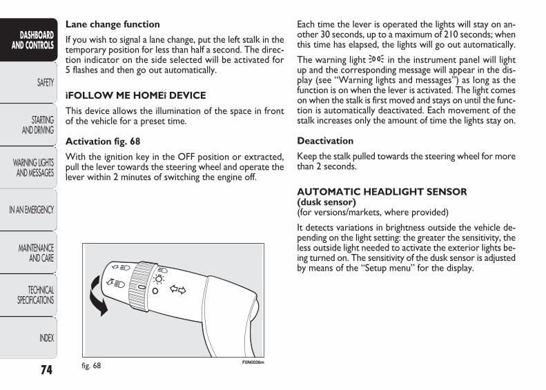
F0N0036mfig. 68
Each time the lever is operated the lights will stay on an-other 30 seconds, up to a maximum of 210 seconds; whenthis time has elapsed, the lights will go out automatically.
The warning light 3 in the instrument panel will lightup and the corresponding message will appear in the dis-play (see “Warning lights and messages”) as long as thefunction is on when the lever is activated. The light comeson when the stalk is first moved and stays on until the func-tion is automatically deactivated. Each movement of thestalk increases only the amount of time the lights stay on.
Deactivation
Keep the stalk pulled towards the steering wheel for morethan 2 seconds.
AUTOMATIC HEADLIGHT SENSOR (dusk sensor) (for versions/markets, where provided)
It detects variations in brightness outside the vehicle de-pending on the light setting: the greater the sensitivity, theless outside light needed to activate the exterior lights be-ing turned on. The sensitivity of the dusk sensor is adjustedby means of the “Setup menu” for the display.
Lane change function
If you wish to signal a lane change, put the left stalk in thetemporary position for less than half a second. The direc-tion indicator on the side selected will be activated for 5 flashes and then go out automatically.
ìFOLLOW ME HOMEî DEVICE
This device allows the illumination of the space in frontof the vehicle for a preset time.
Activation fig. 68
With the ignition key in the OFF position or extracted,pull the lever towards the steering wheel and operate thelever within 2 minutes of switching the engine off.
74
DASHBOARD AND CONTROLS
SAFETY
STARTING AND DRIVING
WARNING LIGHTSAND MESSAGES
IN AN EMERGENCY
MAINTENANCE AND CARE
TECHNICAL SPECIFICATIONS
INDEX
037-122 DUCATO LUM EN 11-02-2010 14:26 Pagina 74
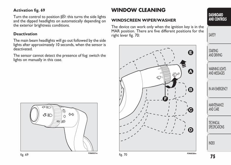
F0N0037mfig. 69
WINDOW CLEANING
WINDSCREEN WIPER/WASHER
The device can work only when the ignition key is in theMAR position. There are five different positions for theright lever fig. 70:
Activation fig. 69
Turn the control to position 2A : this turns the side lightsand the dipped headlights on automatically depending onthe exterior brightness conditions.
Deactivation
The main beam headlights will go out followed by the sidelights after approximately 10 seconds, when the sensor isdeactivated.
The sensor cannot detect the presence of fog: switch thelights on manually in this case.
75
DASHBOARD AND CONTROLS
SAFETY
STARTING AND DRIVING
WARNING LIGHTSAND MESSAGES
IN AN EMERGENCY
MAINTENANCE AND CARE
TECHNICAL SPECIFICATIONS
INDEX
fig. 70 F0N0038m
037-122 DUCATO LUM EN 11-02-2010 14:26 Pagina 75
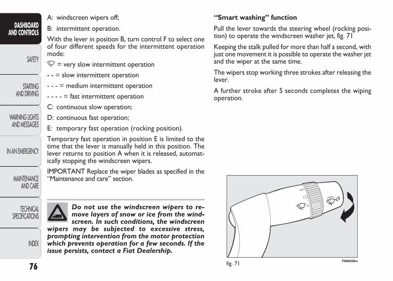
F0N0039mfig. 71
“Smart washing” function
Pull the lever towards the steering wheel (rocking posi-tion) to operate the windscreen washer jet, fig. 71
Keeping the stalk pulled for more than half a second, withjust one movement it is possible to operate the washer jetand the wiper at the same time.
The wipers stop working three strokes after releasing thelever.
A further stroke after 5 seconds completes the wipingoperation.
A: windscreen wipers off;
B: intermittent operation.
With the lever in position B, turn control F to select oneof four different speeds for the intermittent operationmode:
, = very slow intermittent operation
- - = slow intermittent operation
- - - = medium intermittent operation
- - - - = fast intermittent operation
C: continuous slow operation;
D: continuous fast operation;
E: temporary fast operation (rocking position).
Temporary fast operation in position E is limited to thetime that the lever is manually held in this position. Thelever returns to position A when it is released, automat-ically stopping the windscreen wipers.
IMPORTANT Replace the wiper blades as specified in the“Maintenance and care” section.
76
DASHBOARD AND CONTROLS
SAFETY
STARTING AND DRIVING
WARNING LIGHTSAND MESSAGES
IN AN EMERGENCY
MAINTENANCE AND CARE
TECHNICAL SPECIFICATIONS
INDEX
Do not use the windscreen wipers to re-move layers of snow or ice from the wind-screen. In such conditions, the windscreen
wipers may be subjected to excessive stress,prompting intervention from the motor protectionwhich prevents operation for a few seconds. If theissue persists, contact a Fiat Dealership.
037-122 DUCATO LUM EN 11-02-2010 14:26 Pagina 76
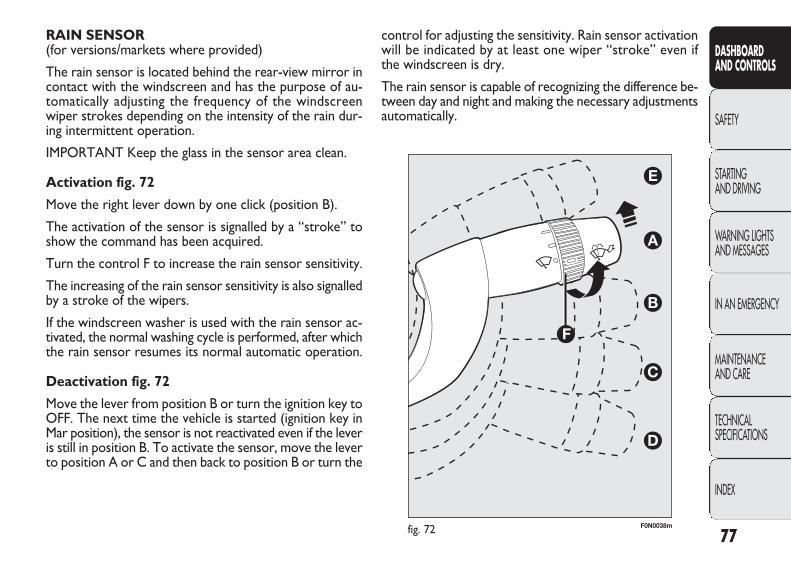
control for adjusting the sensitivity. Rain sensor activationwill be indicated by at least one wiper “stroke” even ifthe windscreen is dry.
The rain sensor is capable of recognizing the difference be-tween day and night and making the necessary adjustmentsautomatically.
RAIN SENSOR (for versions/markets where provided)
The rain sensor is located behind the rear-view mirror incontact with the windscreen and has the purpose of au-tomatically adjusting the frequency of the windscreenwiper strokes depending on the intensity of the rain dur-ing intermittent operation.
IMPORTANT Keep the glass in the sensor area clean.
Activation fig. 72
Move the right lever down by one click (position B).
The activation of the sensor is signalled by a “stroke” toshow the command has been acquired.
Turn the control F to increase the rain sensor sensitivity.
The increasing of the rain sensor sensitivity is also signalledby a stroke of the wipers.
If the windscreen washer is used with the rain sensor ac-tivated, the normal washing cycle is performed, after whichthe rain sensor resumes its normal automatic operation.
Deactivation fig. 72
Move the lever from position B or turn the ignition key toOFF. The next time the vehicle is started (ignition key inMar position), the sensor is not reactivated even if the leveris still in position B. To activate the sensor, move the leverto position A or C and then back to position B or turn the
77
DASHBOARD AND CONTROLS
SAFETY
STARTING AND DRIVING
WARNING LIGHTSAND MESSAGES
IN AN EMERGENCY
MAINTENANCE AND CARE
TECHNICAL SPECIFICATIONS
INDEX
fig. 72 F0N0038m
037-122 DUCATO LUM EN 11-02-2010 14:26 Pagina 77

F0N0040mfig. 73
CRUISE CONTROL (for versions/markets where provided)
This is an electronic driving aid that allows you to driveat a speed of above 30 km/h on long and straight dry roads(e.g. motorways) with few driving changes at a preset speedwithout having to press the accelerator pedal. It is there-fore not recommended to use this device on country roadswith traffic. Do not use it in town.
DEVICE ACTIVATION fig. 73
Turn the control A to the ON position.
The Cruise Control cannot be engaged in 1st or reversegear. It is advisable to engage it in 4th or higher gears.
78
DASHBOARD AND CONTROLS
SAFETY
STARTING AND DRIVING
WARNING LIGHTSAND MESSAGES
IN AN EMERGENCY
MAINTENANCE AND CARE
TECHNICAL SPECIFICATIONS
INDEX
HEADLIGHT WASHERS (for versions/markets where provided)
The headlight washers are “retractable”, i.e. they are lo-cated inside the front bumper and they are activated when(with dipped beams on) the windscreen washer is oper-ated.
IMPORTANT Check the correct operation and cleanli-ness of the jets at regular intervals.
Streaks of water may cause unnecessaryblade movements.
WARNING
037-122 DUCATO LUM EN 11-02-2010 14:26 Pagina 78
INCREASING THE MEMORISED SPEED
This can be done in two ways:
❒ by pressing the accelerator and then memorising thenew speed reached;
or
❒ by moving the lever upwards (+).
Each movement of the stalk will correspond to an increasein speed of about 1 km/h, while keeping the stalk held up-wards will continuously increase the speed.
REDUCING THE MEMORISED SPEED
This can be done in two ways:
❒ by turning the device off and then storing a new speed;
or
❒ by moving the lever downwards (–) until reaching thenew speed which will be memorised automatically.
Each movement of the stalk will correspond to a reduc-tion in speed of about 1 km/h, while keeping the stalk helddownwards will continuously reduce the speed.
When travelling downhill with the device engaged, the ve-hicle speed may slightly exceed the memorised one.
When the device is activated the warning light Ü comeson together with the relevant message on the instrumentpanel.
STORING VEHICLE SPEED
Proceed as follows:
❒ turn control Ax to ON and press the accelerator pedalso that the vehicle reaches the desired speed;
❒ move the levers upwards (+) for at least one second,then release it. The car speed is memorised and it istherefore possible to release the accelerator pedal.
If necessary (when overtaking for instance) acceleration ispossible by simply pressing the accelerator pedal: releas-ing the accelerator pedal, the car will return to the speedmemorised previously.
RESTORING THE MEMORISED SPEED
If the device has been switched off, for example by press-ing the brake or clutch pedal, the memorised speed canbe restored as follows:
❒ accelerate gradually until reaching a speed approach-ing the memorised speed;
❒ engage the gear selected at the time of speed memo-rising;
❒ press the button RES B.
79
DASHBOARD AND CONTROLS
SAFETY
STARTING AND DRIVING
WARNING LIGHTSAND MESSAGES
IN AN EMERGENCY
MAINTENANCE AND CARE
TECHNICAL SPECIFICATIONS
INDEX
037-122 DUCATO LUM EN 11-02-2010 14:26 Pagina 79
SWITCHING THE DEVICE OFF
The device can be switched off by the driver in the fol-lowing ways:
❒ turning the control A to the OFF position;
❒ turning the engine off;
❒ pressing the brake pedal or operating the handbrake;
❒ pressing the clutch pedal;
❒ requesting a gear shift with an automatic transmissionin sequential mode;
❒ with vehicle speed below the set limit;
❒ by pressing the accelerator pedal; in this case the sys-tem is not really switched off but the request for ac-celeration takes priority over the system. The cruisecontrol is, however, active and it will not be necessaryto press the RES button to restore the previous con-ditions after the acceleration is over.
The device is automatically switched off in the followingcases:
❒ if the ABS or ESP systems cut-in;
❒ if there is a system failure.
80
DASHBOARD AND CONTROLS
SAFETY
STARTING AND DRIVING
WARNING LIGHTSAND MESSAGES
IN AN EMERGENCY
MAINTENANCE AND CARE
TECHNICAL SPECIFICATIONS
INDEX
While travelling with the device engaged,do not place the gear lever in neutral.
WARNING
In case of malfunctioning or if the deviceis faulty, turn the control A to OFF and
contact a Fiat Dealership, after checking thatthe protective fuse has not blown.
WARNING
037-122 DUCATO LUM EN 11-02-2010 14:26 Pagina 80
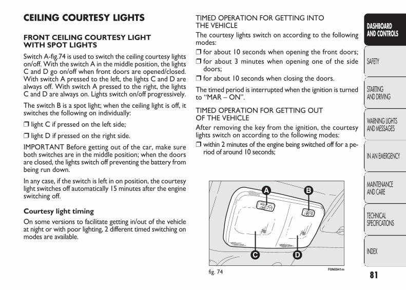
F0N0041mfig. 74
TIMED OPERATION FOR GETTING INTO THE VEHICLEThe courtesy lights switch on according to the followingmodes:❒ for about 10 seconds when opening the front doors;❒ for about 3 minutes when opening one of the side
doors;❒ for about 10 seconds when closing the doors.
The timed period is interrupted when the ignition is turnedto “MAR – ON”.
TIMED OPERATION FOR GETTING OUT OF THE VEHICLEAfter removing the key from the ignition, the courtesylights switch on according to the following modes:❒ within 2 minutes of the engine being switched off for a pe-
riod of around 10 seconds;
CEILING COURTESY LIGHTS
FRONT CEILING COURTESY LIGHT WITH SPOT LIGHTS
Switch A-fig.74 is used to switch the ceiling courtesy lightson/off. With the switch A in the middle position, the lightsC and D go on/off when front doors are opened/closed.With switch A pressed to the left, the lights C and D arealways off. With switch A pressed to the right, the lightsC and D are always on. Lights switch on/off progressively.
The switch B is a spot light; when the ceiling light is off, itswitches the following on individually:
❒ light C if pressed on the left side;
❒ light D if pressed on the right side.
IMPORTANT Before getting out of the car, make sureboth switches are in the middle position; when the doorsare closed, the lights switch off preventing the battery frombeing run down.
In any case, if the switch is left in on position, the courtesylight switches off automatically 15 minutes after the engineswitching off.
Courtesy light timing On some versions to facilitate getting in/out of the vehicleat night or with poor lighting, 2 different timed switching onmodes are available.
81
DASHBOARD AND CONTROLS
SAFETY
STARTING AND DRIVING
WARNING LIGHTSAND MESSAGES
IN AN EMERGENCY
MAINTENANCE AND CARE
TECHNICAL SPECIFICATIONS
INDEX
037-122 DUCATO LUM EN 11-02-2010 14:26 Pagina 81
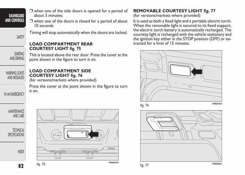
F0N0042mfig. 75 F0N0220mfig. 77
F0N0219mfig. 76
REMOVABLE COURTESY LIGHT fig. 77 (for versions/markets where provided)It is used as both a fixed light and a portable electric torch.When the removable light is secured to its fixed support,the electric torch battery is automatically recharged. Thecourtesy light is recharged with the vehicle stationary andthe ignition key either in the STOP position (OFF) or ex-tracted for a limit of 15 minutes.
❒ when one of the side doors is opened for a period ofabout 3 minutes;
❒ when one of the doors is closed for a period of about10 seconds.
Timing will stop automatically when the doors are locked.
LOAD COMPARTMENT REAR COURTESY LIGHT fig. 75This is located above the rear door. Press the cover at thepoint shown in the figure to turn it on.
LOAD COMPARTMENT SIDE COURTESY LIGHT fig. 76(for versions/markets where provided)Press the cover at the point shown in the figure to turnit on.
82
DASHBOARD AND CONTROLS
SAFETY
STARTING AND DRIVING
WARNING LIGHTSAND MESSAGES
IN AN EMERGENCY
MAINTENANCE AND CARE
TECHNICAL SPECIFICATIONS
INDEX
037-122 DUCATO LUM EN 11-02-2010 14:26 Pagina 82
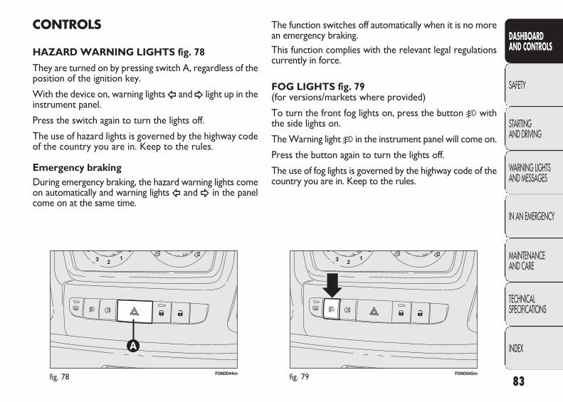
F0N0044mfig. 78 F0N0045mfig. 79
The function switches off automatically when it is no morean emergency braking. This function complies with the relevant legal regulationscurrently in force.
FOG LIGHTS fig. 79 (for versions/markets where provided)
To turn the front fog lights on, press the button 5 withthe side lights on.
The Warning light 5 in the instrument panel will come on.
Press the button again to turn the lights off.
The use of fog lights is governed by the highway code of thecountry you are in. Keep to the rules.
CONTROLS
HAZARD WARNING LIGHTS fig. 78
They are turned on by pressing switch A, regardless of theposition of the ignition key.
With the device on, warning lights Î and ¥ light up in theinstrument panel.
Press the switch again to turn the lights off.
The use of hazard lights is governed by the highway codeof the country you are in. Keep to the rules.
Emergency brakingDuring emergency braking, the hazard warning lights comeon automatically and warning lights Î and ¥ in the panelcome on at the same time.
83
DASHBOARD AND CONTROLS
SAFETY
STARTING AND DRIVING
WARNING LIGHTSAND MESSAGES
IN AN EMERGENCY
MAINTENANCE AND CARE
TECHNICAL SPECIFICATIONS
INDEX
037-122 DUCATO LUM EN 11-02-2010 14:26 Pagina 83
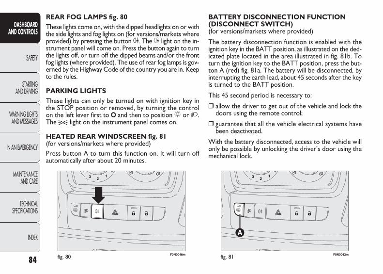
F0N0046mfig. 80 F0N0043mfig. 81
BATTERY DISCONNECTION FUNCTION(DISCONNECT SWITCH) (for versions/markets where provided)
The battery disconnection function is enabled with theignition key in the BATT position, as illustrated on the ded-icated plate located in the area illustrated in fig. 81b. Toturn the ignition key to the BATT position, press the but-ton A (red) fig. 81a. The battery will be disconnected, byinterrupting the earth lead, about 45 seconds after the keyis turned to the BATT position.
This 45 second period is necessary to:
❒ allow the driver to get out of the vehicle and lock thedoors using the remote control;
❒ guarantee that all the vehicle electrical systems havebeen deactivated.
With the battery disconnected, access to the vehicle willonly be possible by unlocking the driver’s door using themechanical lock.
REAR FOG LAMPS fig. 80These lights come on, with the dipped headlights on or withthe side lights and fog lights on (for versions/markets whereprovided) by pressing the button 4. The 4 light on the in-strument panel will come on. Press the button again to turnthe lights off, or turn off the dipped beams and/or the frontfog lights (where provided). The use of rear fog lamps is gov-erned by the Highway Code of the country you are in. Keepto the rules.
PARKING LIGHTSThese lights can only be turned on with ignition key inthe STOP position or removed, by turning the controlon the left lever first to O and then to position 6 or 2.The 3 light on the instrument panel comes on.
HEATED REAR WINDSCREEN fig. 81(for versions/markets where provided)Press button A to turn this function on. It will turn offautomatically after about 20 minutes.
84
DASHBOARD AND CONTROLS
SAFETY
STARTING AND DRIVING
WARNING LIGHTSAND MESSAGES
IN AN EMERGENCY
MAINTENANCE AND CARE
TECHNICAL SPECIFICATIONS
INDEX
037-122 DUCATO LUM EN 11-02-2010 14:26 Pagina 84
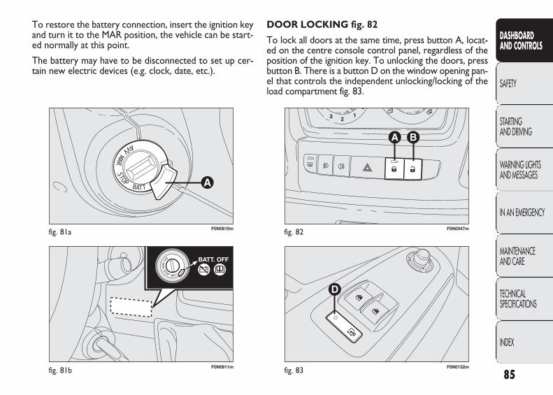
F0N0811mfig. 81b
F0N0810mfig. 81a
F0N0132mfig. 83
F0N0047mfig. 82
DOOR LOCKING fig. 82
To lock all doors at the same time, press button A, locat-ed on the centre console control panel, regardless of theposition of the ignition key. To unlocking the doors, pressbutton B. There is a button D on the window opening pan-el that controls the independent unlocking/locking of theload compartment fig. 83.
To restore the battery connection, insert the ignition keyand turn it to the MAR position, the vehicle can be start-ed normally at this point.
The battery may have to be disconnected to set up cer-tain new electric devices (e.g. clock, date, etc.).
85
DASHBOARD AND CONTROLS
SAFETY
STARTING AND DRIVING
WARNING LIGHTSAND MESSAGES
IN AN EMERGENCY
MAINTENANCE AND CARE
TECHNICAL SPECIFICATIONS
INDEX
037-122 DUCATO LUM EN 11-02-2010 14:26 Pagina 85

F0N0048mfig. 84
ELECTRICAL POWER SUPPLY AND FUEL CUT OFF SWITCH
The vehicle is fitted with a safety switch that, in the eventof a crash, comes into operation by cutting off the fuel sup-ply and turning off the engine as a consequence. When theinertia switch cuts in, this cuts off the fuel supply and alsoactivates the hazard warning lights, side lights and courtesylights while releasing all the doors and displaying a mes-sage; they are deactivated by pressing button A. An addi-tional safety switch is also present that is activated in theevent of impact to cut off the electrical supply. In this way,fuel is prevented from escaping if the pipes are broken tostop the formation of sparks or electrical discharges fol-lowing damage to the vehicle electrical components.
IMPORTANT After an accident, remember to remove thekey from the ignition device to prevent draining the bat-tery. If no fuel leaks or damage to vehicle electrical devices(e.g. headlights) are detected after the impact and the ve-hicle is able to set off again, reactivate the automatic fuelcut off and electrical supply switches (for versions/marketswhere provided) following the procedure described below.
86
DASHBOARD AND CONTROLS
SAFETY
STARTING AND DRIVING
WARNING LIGHTSAND MESSAGES
IN AN EMERGENCY
MAINTENANCE AND CARE
TECHNICAL SPECIFICATIONS
INDEX
If, after a crash, you smell fuel or see leaksfrom the fuel system, do not reset the
switches to avoid the risk of fire.
WARNING
Reactivating the fuel cut-off switch fig. 84
Press the button A to reactivate the fuel cut off switch.
Reactivating the electrical supply cut-off switch(School bus/Minibus) fig. 85
The switch is located on the battery positive terminal. Toreactivate the electrical supply switch, proceed as follows:
❒ press the button A to reset the fuel cut off switch;
❒ press button B to reset the electrical supply switch.
037-122 DUCATO LUM EN 11-02-2010 14:26 Pagina 86
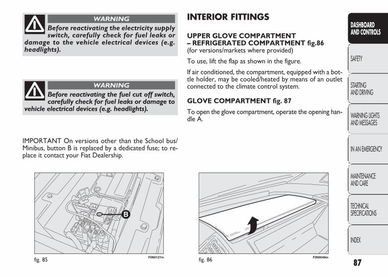
F0N0127mfig. 85
IMPORTANT On versions other than the School bus/Minibus, button B is replaced by a dedicated fuse; to re-place it contact your Fiat Dealership.
87
DASHBOARD AND CONTROLS
SAFETY
STARTING AND DRIVING
WARNING LIGHTSAND MESSAGES
IN AN EMERGENCY
MAINTENANCE AND CARE
TECHNICAL SPECIFICATIONS
INDEX
Before reactivating the electricity supplyswitch, carefully check for fuel leaks or
damage to the vehicle electrical devices (e.g.headlights).
WARNING
Before reactivating the fuel cut off switch,carefully check for fuel leaks or damage to
vehicle electrical devices (e.g. headlights).
WARNING
F0N0049mfig. 86
INTERIOR FITTINGS
UPPER GLOVE COMPARTMENT – REFRIGERATED COMPARTMENT fig.86 (for versions/markets where provided)
To use, lift the flap as shown in the figure.
If air conditioned, the compartment, equipped with a bot-tle holder, may be cooled/heated by means of an outletconnected to the climate control system.
GLOVE COMPARTMENT fig. 87
To open the glove compartment, operate the opening han-dle A.
037-122 DUCATO LUM EN 11-02-2010 14:26 Pagina 87
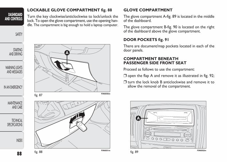
F0N0051mfig. 88
F0N0050mfig. 87
LOCKABLE GLOVE COMPARTMENT fig. 88
Turn the key clockwise/anticlockwise to lock/unlock thelock. To open the glove compartment, use the opening han-dle. The compartment is big enough to hold a laptop computer.
F0N0052mfig. 89
GLOVE COMPARTMENT
The glove compartment A-fig. 89 is located in the middleof the dashboard.
The glove compartment B-fig. 90 is located on the rightof the dashboard above the glove compartment.
DOOR POCKETS fig. 91
There are document/map pockets located in each of thedoor panels.
COMPARTMENT BENEATH PASSENGER SIDE FRONT SEAT
Proceed as follows to use the compartment:
❒ open the flap A and remove it as illustrated in fig. 92;
❒ turn the lock knob B anticlockwise and remove it toallow the removal of the compartment.
88
DASHBOARD AND CONTROLS
SAFETY
STARTING AND DRIVING
WARNING LIGHTSAND MESSAGES
IN AN EMERGENCY
MAINTENANCE AND CARE
TECHNICAL SPECIFICATIONS
INDEX
037-122 DUCATO LUM EN 11-02-2010 14:26 Pagina 88
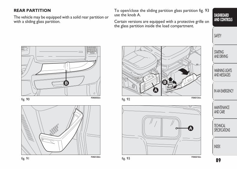
F0N0128mfig. 91
F0N0053mfig. 90
REAR PARTITION
The vehicle may be equipped with a solid rear partition orwith a sliding glass partition.
F0N0218mfig. 93
F0N0134mfig. 92
To open/close the sliding partition glass partition fig. 93use the knob A.
Certain versions are equipped with a protective grille onthe glass partition inside the load compartment.
89
DASHBOARD AND CONTROLS
SAFETY
STARTING AND DRIVING
WARNING LIGHTSAND MESSAGES
IN AN EMERGENCY
MAINTENANCE AND CARE
TECHNICAL SPECIFICATIONS
INDEX
037-122 DUCATO LUM EN 11-02-2010 14:26 Pagina 89
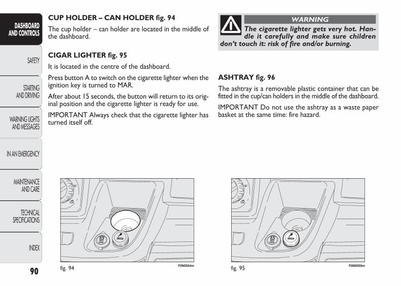
F0N0054mfig. 94 F0N0055mfig. 95
ASHTRAY fig. 96
The ashtray is a removable plastic container that can befitted in the cup/can holders in the middle of the dashboard.
IMPORTANT Do not use the ashtray as a waste paperbasket at the same time: fire hazard.
CUP HOLDER – CAN HOLDER fig. 94
The cup holder – can holder are located in the middle ofthe dashboard.
CIGAR LIGHTER fig. 95
It is located in the centre of the dashboard.
Press button A to switch on the cigarette lighter when theignition key is turned to MAR.
After about 15 seconds, the button will return to its orig-inal position and the cigarette lighter is ready for use.
IMPORTANT Always check that the cigarette lighter hasturned itself off.
90
DASHBOARD AND CONTROLS
SAFETY
STARTING AND DRIVING
WARNING LIGHTSAND MESSAGES
IN AN EMERGENCY
MAINTENANCE AND CARE
TECHNICAL SPECIFICATIONS
INDEX
The cigarette lighter gets very hot. Han-dle it carefully and make sure children
don’t touch it: risk of fire and/or burning.
WARNING
037-122 DUCATO LUM EN 11-02-2010 14:26 Pagina 90
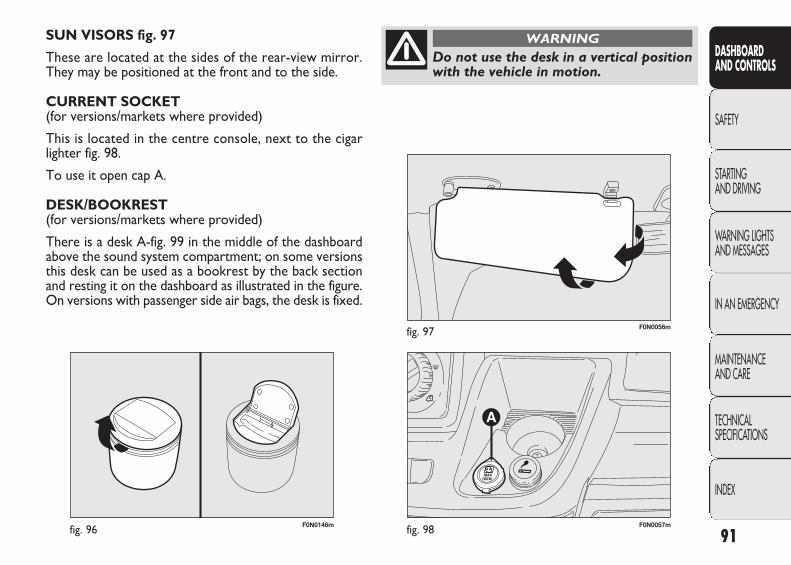
F0N0146mfig. 96 F0N0057mfig. 98
F0N0056mfig. 97
SUN VISORS fig. 97
These are located at the sides of the rear-view mirror.They may be positioned at the front and to the side.
CURRENT SOCKET (for versions/markets where provided)
This is located in the centre console, next to the cigarlighter fig. 98.
To use it open cap A.
DESK/BOOKREST(for versions/markets where provided)
There is a desk A-fig. 99 in the middle of the dashboardabove the sound system compartment; on some versionsthis desk can be used as a bookrest by the back sectionand resting it on the dashboard as illustrated in the figure.On versions with passenger side air bags, the desk is fixed.
91
DASHBOARD AND CONTROLS
SAFETY
STARTING AND DRIVING
WARNING LIGHTSAND MESSAGES
IN AN EMERGENCY
MAINTENANCE AND CARE
TECHNICAL SPECIFICATIONS
INDEX
Do not use the desk in a vertical positionwith the vehicle in motion.
WARNING
037-122 DUCATO LUM EN 11-02-2010 14:26 Pagina 91
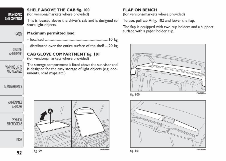
F0N0058mfig. 99 F0N0191mfig. 101
F0N0190mfig. 100
FLAP ON BENCH (for versions/markets where provided)
To use, pull tab A-fig. 102 and lower the flap.
The flap is equipped with two cup holders and a supportsurface with a paper holder clip.
SHELF ABOVE THE CAB fig. 100 (for versions/markets where provided)
This is located above the driver’s cab and is designed tostore light objects.
Maximum permitted load:
– localised .........................................................................10 kg
– distributed over the entire surface of the shelf ....20 kg
CAB GLOVE COMPARTMENT fig. 101 (for versions/markets where provided)
The storage compartment is fitted above the sun visor andis designed for the easy storage of light objects (e.g. doc-uments, road maps etc.).
92
DASHBOARD AND CONTROLS
SAFETY
STARTING AND DRIVING
WARNING LIGHTSAND MESSAGES
IN AN EMERGENCY
MAINTENANCE AND CARE
TECHNICAL SPECIFICATIONS
INDEX
037-122 DUCATO LUM EN 11-02-2010 14:26 Pagina 92
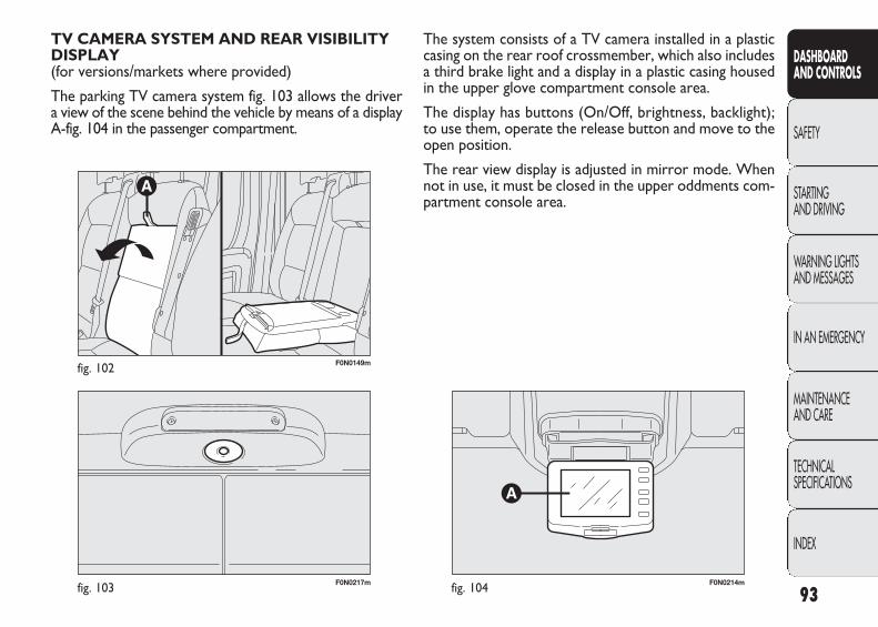
F0N0217mfig. 103
F0N0149mfig. 102
F0N0214mfig. 104
The system consists of a TV camera installed in a plasticcasing on the rear roof crossmember, which also includesa third brake light and a display in a plastic casing housedin the upper glove compartment console area.
The display has buttons (On/Off, brightness, backlight);to use them, operate the release button and move to theopen position.
The rear view display is adjusted in mirror mode. Whennot in use, it must be closed in the upper oddments com-partment console area.
TV CAMERA SYSTEM AND REAR VISIBILITYDISPLAY(for versions/markets where provided)
The parking TV camera system fig. 103 allows the driver a view of the scene behind the vehicle by means of a displayA-fig. 104 in the passenger compartment.
93
DASHBOARD AND CONTROLS
SAFETY
STARTING AND DRIVING
WARNING LIGHTSAND MESSAGES
IN AN EMERGENCY
MAINTENANCE AND CARE
TECHNICAL SPECIFICATIONS
INDEX
037-122 DUCATO LUM EN 11-02-2010 14:26 Pagina 93

F0N0215mfig. 105
Notes on use
To clean the TV camera, it is advisable to use a non-abra-sive cloth when the protective glass is dirty or iced over(on the outside). It is absolutely necessary to avoid usingany tool for cleaning as this could scratch the glass.
It is also advisable to use a dry non-abrasive cloth whencleaning the display. The dust that settles on the displaymay be removed with special brushes. Avoid using any de-tergent for cleaning.
The display glass could break in the event of impact. In thiscase, do not touch the liquid crystal that emerges from thedisplay. If this occurs, quickly wash the contaminated partswith soap and water.
ACTIVATION
The system is activated with the ignition on and reverseengaged or by means of a dedicated button. If the vehicleis in motion, e.g. during a reversing manoeuvre, the sys-tem will operate up to a speed of 15 km/h and go off whena speed of approximately 18 km/h is exceeded. When re-verse is deactivated, the image will appear on the displayfor a further 5 seconds.
GENERAL WARNINGS
Area of visibility
The area of visibility may vary according to the vehicle po-sition (full load condition included), according to the vehi-cle specification and according to weather conditions (highbrightness, rain, snow and fog). Visibility may be reducedduring poor lighting or full load conditions.
The area covered by the TV camera is approximately 3 min length and approximately a maximum of 5.5 m in widthfig. 105.
94
DASHBOARD AND CONTROLS
SAFETY
STARTING AND DRIVING
WARNING LIGHTSAND MESSAGES
IN AN EMERGENCY
MAINTENANCE AND CARE
TECHNICAL SPECIFICATIONS
INDEX
037-122 DUCATO LUM EN 11-02-2010 14:26 Pagina 94
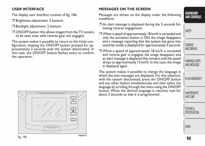
F0N0216mfig. 106
MESSAGES ON THE SCREEN
Messages are shown on the display under the followingconditions:
❒ An alert message is displayed during the 5 seconds fol-lowing reverse engagement.
❒ When a speed of approximately 18 km/h is exceeded andonly the activation button is ON, the image disappearsand a message reporting that the system has gone intostand-by mode is displayed for approximately 5 seconds.
❒ When a speed of approximately 18 km/h is exceededand reverse gear is engaged, the image disappears andan alert message is displayed that remains until the speeddrops to approximately 15 km/h. In this case, the imageis displayed again.
The system makes it possible to change the language inwhich the text messages are displayed. For this selection,with the system deactivated, press the ON/OFF buttonand any other button simultaneously and then select thelanguage by scrolling through the menu using the ON/OFFbutton. When the desired language is reached, wait forabout 3 seconds so that it is programmed.
USER INTERFACE
The display user interface consists of fig. 106:
❒ Brightness adjustment: 2 buttons
❒ Backlight adjustment: 2 buttons
❒ ON/OFF button: this allows images from the TV camerato be seen even with reverse gear not engaged.
The system makes it possible to return to the initial con-figuration, keeping the ON/OFF button pressed for ap-proximately 3 seconds with the system deactivated. Inthis case, the ON/OFF button flashes twice to confirmthe operation.
95
DASHBOARD AND CONTROLS
SAFETY
STARTING AND DRIVING
WARNING LIGHTSAND MESSAGES
IN AN EMERGENCY
MAINTENANCE AND CARE
TECHNICAL SPECIFICATIONS
INDEX
037-122 DUCATO LUM EN 11-02-2010 14:26 Pagina 95
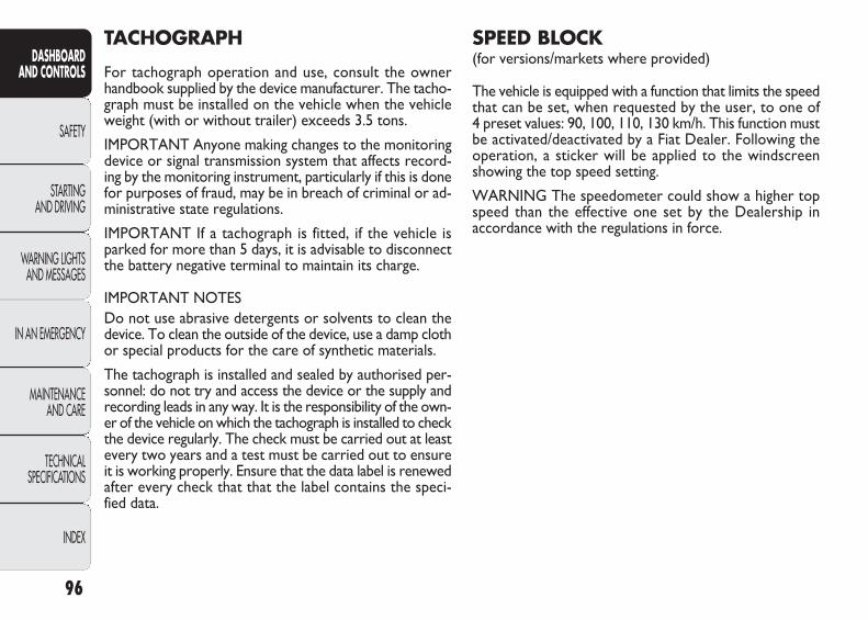
SPEED BLOCK (for versions/markets where provided)
The vehicle is equipped with a function that limits the speedthat can be set, when requested by the user, to one of 4 preset values: 90, 100, 110, 130 km/h. This function mustbe activated/deactivated by a Fiat Dealer. Following theoperation, a sticker will be applied to the windscreenshowing the top speed setting.
WARNING The speedometer could show a higher topspeed than the effective one set by the Dealership in accordance with the regulations in force.
TACHOGRAPH
For tachograph operation and use, consult the ownerhandbook supplied by the device manufacturer. The tacho-graph must be installed on the vehicle when the vehicleweight (with or without trailer) exceeds 3.5 tons.
IMPORTANT Anyone making changes to the monitoringdevice or signal transmission system that affects record-ing by the monitoring instrument, particularly if this is donefor purposes of fraud, may be in breach of criminal or ad-ministrative state regulations.
IMPORTANT If a tachograph is fitted, if the vehicle isparked for more than 5 days, it is advisable to disconnectthe battery negative terminal to maintain its charge.
IMPORTANT NOTESDo not use abrasive detergents or solvents to clean thedevice. To clean the outside of the device, use a damp clothor special products for the care of synthetic materials.
The tachograph is installed and sealed by authorised per-sonnel: do not try and access the device or the supply andrecording leads in any way. It is the responsibility of the own-er of the vehicle on which the tachograph is installed to checkthe device regularly. The check must be carried out at leastevery two years and a test must be carried out to ensureit is working properly. Ensure that the data label is renewedafter every check that that the label contains the speci-fied data.
96
DASHBOARD AND CONTROLS
SAFETY
STARTING AND DRIVING
WARNING LIGHTSAND MESSAGES
IN AN EMERGENCY
MAINTENANCE AND CARE
TECHNICAL SPECIFICATIONS
INDEX
037-122 DUCATO LUM EN 11-02-2010 14:26 Pagina 96

F0N0800mfig. 107 F0N0059mfig. 109
F0N0801mfig. 108
activation of the interior courtesy lights and a double signalfrom the direction indicators. All the doors are unlockedby turning the metal insert in the door lock on the driver’sside fig. 109 anticlockwise. With the battery disconnected,access to the vehicle will only be possible by unlocking thedriver’s door using the mechanical lock.
DOORSCENTRAL DOOR LOCKING/UNLOCKING SYSTEM
Locking the doors from the outside
With the doors shut, press button Á on the remote con-trol fig. 107 or slide the metal insert into the lock of thedoor on the driver’s side and turn it clockwise. The doorswill be locked only if all doors are shut. If one or moredoors are open after pressing button Á on the remotecontrol fig. 107, the direction indicators and the LED inthe button A-fig. 110 flash quickly for approximately 3 sec-onds. The Buttons A and B fig. 110 are disabled with thefunction activated. Pressing the button Á in the remotecontrol fig. 107 twice quickly activates the dead lock (see“Dead lock” paragraph).
Door unlocking from the outside
Press the button Q fig. 107 or Ë fig. 108 briefly, dependingon the version, to release the front doors remotely, for timed
97
DASHBOARD AND CONTROLS
SAFETY
STARTING AND DRIVING
WARNING LIGHTSAND MESSAGES
IN AN EMERGENCY
MAINTENANCE AND CARE
TECHNICAL SPECIFICATIONS
INDEX
037-122 DUCATO LUM EN 11-02-2010 14:26 Pagina 97

F0N0047mfig. 110
IMPORTANT With the central locking engaged, pullingthe opening lever for one of the front doors switches offthe central locking function. Individual doors can be un-locked by pulling the internal handle of one of the reardoors.
If a power supply is not present (blown fuse, battery dis-connected, etc.) it is, however, possible to lock the doorsmanually.
After exceeding 20 km/h, all the doors will be locked au-tomatically if the setup menu function has been selected(see ìMultifunction displayî paragraph in this section).
LOAD COMPARTMENT BUTTON fig. 111
Lock activation is indicated by the LED in the button.
The LED comes on in the following cases:
❒ after each door lock command generated by the actu-al button or by button Á in the dashboard;
❒ when the instrument panel is activated;
❒ upon opening of one of the front doors;
❒ when the door is locked at 20 km/h (if activated fromthe menu).
The lock is turned off when one of the load compartmentdoors is opened or on a door release request (load com-partment or centralised) or an unlocking request from theremote control/door catch.
Door locking/unlocking from the inside
Press the button A-fig. 110 to lock the doors, press but-ton B to unlock the doors. The locking/unlocking actionstake place centrally (front and rear). When the doors arelocked, the LED in the button A is on and pressing but-ton B brings about central unlocking of all the doors andturns off the warning light. When the doors are unlocked,the LED is off and pressing the button brings about cen-tral locking of all the doors. The doors will be lockedonly if all the doors are properly shut.
Following the locking of the doors using:
❒ remote control;
❒ door catch.
it will not be possible to unlock the doors using button A-fig. 110 located in the controls in the dashboard.
98
DASHBOARD AND CONTROLS
SAFETY
STARTING AND DRIVING
WARNING LIGHTSAND MESSAGES
IN AN EMERGENCY
MAINTENANCE AND CARE
TECHNICAL SPECIFICATIONS
INDEX
037-122 DUCATO LUM EN 11-02-2010 14:27 Pagina 98
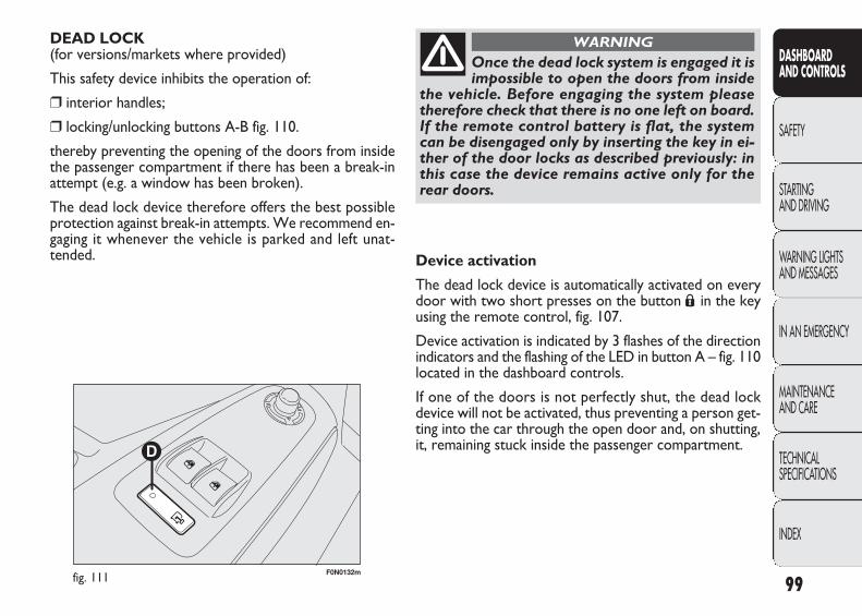
DEAD LOCK(for versions/markets where provided)
This safety device inhibits the operation of:
❒ interior handles;
❒ locking/unlocking buttons A-B fig. 110.
thereby preventing the opening of the doors from insidethe passenger compartment if there has been a break-inattempt (e.g. a window has been broken).
The dead lock device therefore offers the best possibleprotection against break-in attempts. We recommend en-gaging it whenever the vehicle is parked and left unat-tended.
F0N0132mfig. 111 99
DASHBOARD AND CONTROLS
SAFETY
STARTING AND DRIVING
WARNING LIGHTSAND MESSAGES
IN AN EMERGENCY
MAINTENANCE AND CARE
TECHNICAL SPECIFICATIONS
INDEX
Once the dead lock system is engaged it isimpossible to open the doors from inside
the vehicle. Before engaging the system pleasetherefore check that there is no one left on board.If the remote control battery is flat, the systemcan be disengaged only by inserting the key in ei-ther of the door locks as described previously: inthis case the device remains active only for therear doors.
WARNING
Device activation
The dead lock device is automatically activated on everydoor with two short presses on the button Á in the keyusing the remote control, fig. 107.
Device activation is indicated by 3 flashes of the directionindicators and the flashing of the LED in button A – fig. 110located in the dashboard controls.
If one of the doors is not perfectly shut, the dead lockdevice will not be activated, thus preventing a person get-ting into the car through the open door and, on shutting,it, remaining stuck inside the passenger compartment.
037-122 DUCATO LUM EN 11-02-2010 14:27 Pagina 99
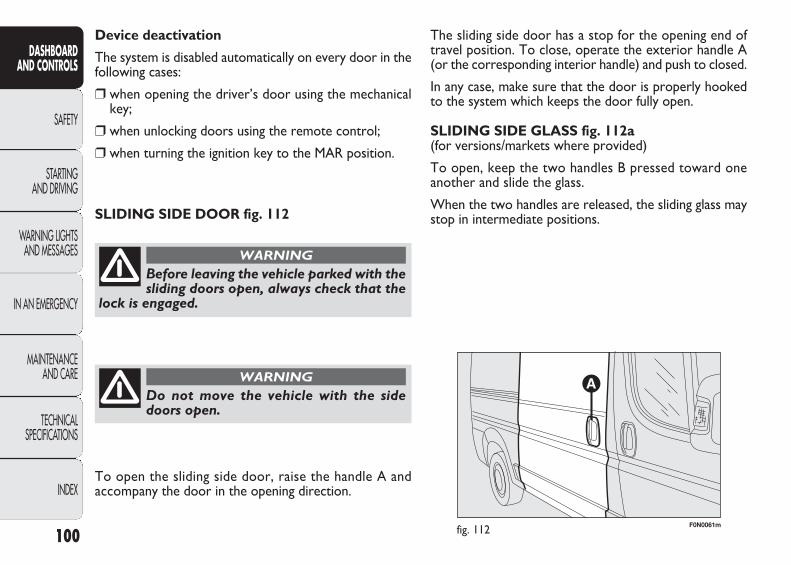
The sliding side door has a stop for the opening end oftravel position. To close, operate the exterior handle A(or the corresponding interior handle) and push to closed.
In any case, make sure that the door is properly hookedto the system which keeps the door fully open.
SLIDING SIDE GLASS fig. 112a (for versions/markets where provided)
To open, keep the two handles B pressed toward oneanother and slide the glass.
When the two handles are released, the sliding glass maystop in intermediate positions.
Device deactivation
The system is disabled automatically on every door in thefollowing cases:
❒ when opening the driver’s door using the mechanicalkey;
❒ when unlocking doors using the remote control;
❒ when turning the ignition key to the MAR position.
100
DASHBOARD AND CONTROLS
SAFETY
STARTING AND DRIVING
WARNING LIGHTSAND MESSAGES
IN AN EMERGENCY
MAINTENANCE AND CARE
TECHNICAL SPECIFICATIONS
INDEX
Before leaving the vehicle parked with thesliding doors open, always check that the
lock is engaged.
WARNING
Do not move the vehicle with the sidedoors open.
WARNING
SLIDING SIDE DOOR fig. 112
F0N0061mfig. 112
To open the sliding side door, raise the handle A and accompany the door in the opening direction.
037-122 DUCATO LUM EN 11-02-2010 14:27 Pagina 100

F0N0240mfig. 112a F0N0176mfig. 113
MOVING FOOTBOARD fig. 113 (for versions/markets where provided)
When the side door of the passenger compartment or lug-gage compartment is opened, a footboard emerges fromthe lower part of the floorpan to make it easier to boardthe vehicle.
101
DASHBOARD AND CONTROLS
SAFETY
STARTING AND DRIVING
WARNING LIGHTSAND MESSAGES
IN AN EMERGENCY
MAINTENANCE AND CARE
TECHNICAL SPECIFICATIONS
INDEX
Before setting off after parking or beforemoving the vehicle in any way, ensure the
footboard is fully stowed away. Because the move-ment of the footboard is controlled by that of thesliding side door, incomplete stowing of the foot-board or non-closure of the rear doors is indicat-ed by a warning light ´ in the instrument panel.
WARNING
REAR SWING DOORS (TWO)
Manual opening of the first swing door from the outside
Turn the key anticlockwise fig. 109 or press button ∞ onthe remote control and operate the handle A-fig. 114 inthe arrow direction.
Manual closure of the first swing door from the inside fig. 115(for versions/markets where provided)
Pull handle B in the arrowed direction.
Manual closure of the first swing door from the outside
Turn the key clockwise or press button Á on the key withremote control. Close the left door first, followed by theright door.
037-122 DUCATO LUM EN 11-02-2010 14:27 Pagina 101

F0N0130mfig. 115
F0N0129mfig. 114
F0N0132mfig. 117
F0N0131mfig. 116
Electrical closure from inside fig. 117
Close the two rear swing doors (first the left, then theright) and press button D located in the window controlpanel.
Manual opening of the second swing door, fig. 116
Pull handle C in the arrowed direction.
The rear swing doors are equipped with a spring loadedsystem that locks them at an approx. angle of 90 degreesduring opening.
102
DASHBOARD AND CONTROLS
SAFETY
STARTING AND DRIVING
WARNING LIGHTSAND MESSAGES
IN AN EMERGENCY
MAINTENANCE AND CARE
TECHNICAL SPECIFICATIONS
INDEX
037-122 DUCATO LUM EN 11-02-2010 14:27 Pagina 102
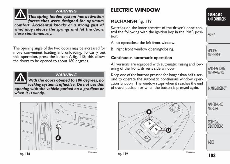
F0N0188mfig. 118 F0N0062mfig. 119
ELECTRIC WINDOW
MECHANISM fig. 119
Switches on the inner armrest of the driver’s door con-trol the following with the ignition key in the MAR posi-tion:
A to open/close the left front window;
B right front window opening/closing.
Continuous automatic operation
All versions are equipped with automatic raising and low-ering of the front, driver’s side window.
Keep one of the buttons pressed for longer than half a sec-ond to operate the automatic continuous window oper-ation function . The window stops when it reaches the endof travel position or when the button is pressed again.
The opening angle of the two doors may be increased formore convenient loading and unloading. To carry out this operation, press the button A-fig. 118; this allows the doors to be opened to about 180 degrees.
103
DASHBOARD AND CONTROLS
SAFETY
STARTING AND DRIVING
WARNING LIGHTSAND MESSAGES
IN AN EMERGENCY
MAINTENANCE AND CARE
TECHNICAL SPECIFICATIONS
INDEX
This spring loaded system has activationforces that were designed for optimum
comfort. Accidental knocks or a strong gust ofwind may release the springs and let the doorsclose spontaneously.
WARNING
With the doors opened to 180 degrees, nolocking system is effective. Do not use this
opening with the vehicle parked on a gradient orwhen it is windy.
WARNING
037-122 DUCATO LUM EN 11-02-2010 14:27 Pagina 103
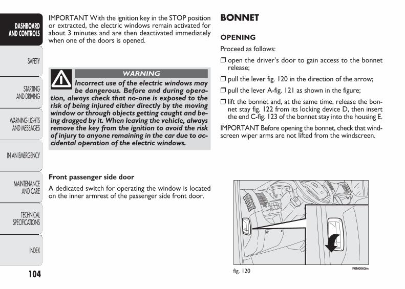
F0N0063mfig. 120
BONNET
OPENING
Proceed as follows:
❒ open the driver’s door to gain access to the bonnetrelease;
❒ pull the lever fig. 120 in the direction of the arrow;
❒ pull the lever A-fig. 121 as shown in the figure;
❒ lift the bonnet and, at the same time, release the bon-net stay fig. 122 from its locking device D, then insertthe end C-fig. 123 of the bonnet stay into the housing E.
IMPORTANT Before opening the bonnet, check that wind-screen wiper arms are not lifted from the windscreen.
IMPORTANT With the ignition key in the STOP positionor extracted, the electric windows remain activated forabout 3 minutes and are then deactivated immediatelywhen one of the doors is opened.
104
DASHBOARD AND CONTROLS
SAFETY
STARTING AND DRIVING
WARNING LIGHTSAND MESSAGES
IN AN EMERGENCY
MAINTENANCE AND CARE
TECHNICAL SPECIFICATIONS
INDEX
Incorrect use of the electric windows maybe dangerous. Before and during opera-
tion, always check that no-one is exposed to therisk of being injured either directly by the movingwindow or through objects getting caught and be-ing dragged by it. When leaving the vehicle, alwaysremove the key from the ignition to avoid the riskof injury to anyone remaining in the car due to ac-cidental operation of the electric windows.
WARNING
Front passenger side door
A dedicated switch for operating the window is locatedon the inner armrest of the passenger side front door.
037-122 DUCATO LUM EN 11-02-2010 14:27 Pagina 104
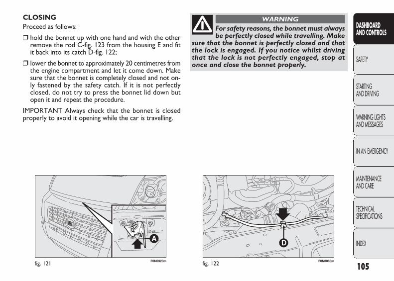
F0N0323mfig. 121 F0N0065mfig. 122
CLOSING Proceed as follows:
❒ hold the bonnet up with one hand and with the otherremove the rod C-fig. 123 from the housing E and fit it back into its catch D-fig. 122;
❒ lower the bonnet to approximately 20 centimetres fromthe engine compartment and let it come down. Makesure that the bonnet is completely closed and not on-ly fastened by the safety catch. If it is not perfectlyclosed, do not try to press the bonnet lid down butopen it and repeat the procedure.
IMPORTANT Always check that the bonnet is closedproperly to avoid it opening while the car is travelling.
105
DASHBOARD AND CONTROLS
SAFETY
STARTING AND DRIVING
WARNING LIGHTSAND MESSAGES
IN AN EMERGENCY
MAINTENANCE AND CARE
TECHNICAL SPECIFICATIONS
INDEX
For safety reasons, the bonnet must alwaysbe perfectly closed while travelling. Make
sure that the bonnet is perfectly closed and thatthe lock is engaged. If you notice whilst drivingthat the lock is not perfectly engaged, stop atonce and close the bonnet properly.
WARNING
037-122 DUCATO LUM EN 11-02-2010 14:27 Pagina 105
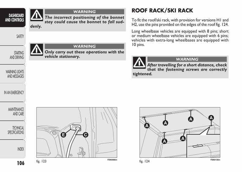
F0N0066mfig. 123 F0N0138mfig. 124
ROOF RACK/SKI RACK
To fit the roof/ski rack, with provision for versions H1 andH2, use the pins provided on the edges of the roof fig. 124.
Long wheelbase vehicles are equipped with 8 pins; shortor medium wheelbase vehicles are equipped with 6 pins;vehicles with extra-long wheelbases are equipped with10 pins.
106
DASHBOARD AND CONTROLS
SAFETY
STARTING AND DRIVING
WARNING LIGHTSAND MESSAGES
IN AN EMERGENCY
MAINTENANCE AND CARE
TECHNICAL SPECIFICATIONS
INDEX
Only carry out these operations with thevehicle stationary.
WARNING
The incorrect positioning of the bonnetstay could cause the bonnet to fall sud-
denly.
WARNING
After travelling for a short distance, checkthat the fastening screws are correctly
tightened.
WARNING
037-122 DUCATO LUM EN 11-02-2010 14:27 Pagina 106

HEADLIGHTS
LIGHT BEAM DIRECTION
The correct direction of the headlights is essential for thecomfort and safety of the driver and other road users.To ensure the best visibility conditions when travelling withthe headlights on the headlight alignment must be correct.Contact a Fiat Dealership to have the direction checkedand, if necessary, adjusted.
HEADLIGHT ALIGNMENT CORRECTOR
This device works with the key in the MAR position andthe dipped headlights on. The vehicle tilts backwards whenit is laden raising the beam. The beams must therefore beaimed again in this case.
Headlight alignment adjustment, fig. 125
Press buttons Ò and in the control panel for the adjustment.
The display located on the instrument panel provides thevisual indication of the positions during the adjustmentoperation.
IMPORTANT Check the beam alignment every time theload transported changes.
IMPORTANT Follow the instructions contained in the as-sembly kit carefully. Assembly must be performed by qual-ified personnel.
107
DASHBOARD AND CONTROLS
SAFETY
STARTING AND DRIVING
WARNING LIGHTSAND MESSAGES
IN AN EMERGENCY
MAINTENANCE AND CARE
TECHNICAL SPECIFICATIONS
INDEX
Respect the regulations in force concerningmaximum clearance.
Distribute the load evenly and when dri-ving, bear in mind the increased sensitivi-
ty of the vehicle to side wind.
WARNING
Never exceed the permitted weight (see“Technical data” section).
037-122 DUCATO LUM EN 11-02-2010 14:27 Pagina 107
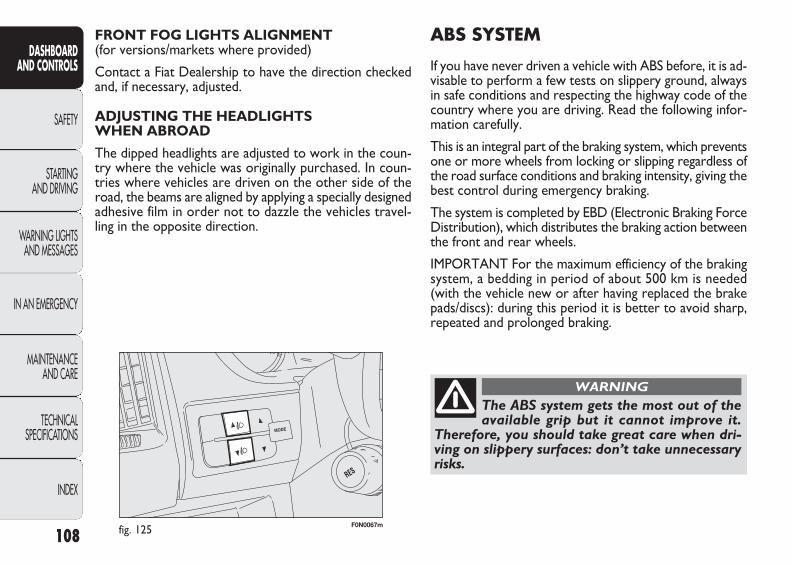
F0N0067mfig. 125
ABS SYSTEM
If you have never driven a vehicle with ABS before, it is ad-visable to perform a few tests on slippery ground, alwaysin safe conditions and respecting the highway code of thecountry where you are driving. Read the following infor-mation carefully.
This is an integral part of the braking system, which preventsone or more wheels from locking or slipping regardless ofthe road surface conditions and braking intensity, giving thebest control during emergency braking.
The system is completed by EBD (Electronic Braking ForceDistribution), which distributes the braking action betweenthe front and rear wheels.
IMPORTANT For the maximum efficiency of the brakingsystem, a bedding in period of about 500 km is needed(with the vehicle new or after having replaced the brakepads/discs): during this period it is better to avoid sharp,repeated and prolonged braking.
FRONT FOG LIGHTS ALIGNMENT (for versions/markets where provided)
Contact a Fiat Dealership to have the direction checkedand, if necessary, adjusted.
ADJUSTING THE HEADLIGHTS WHEN ABROAD
The dipped headlights are adjusted to work in the coun-try where the vehicle was originally purchased. In coun-tries where vehicles are driven on the other side of theroad, the beams are aligned by applying a specially designedadhesive film in order not to dazzle the vehicles travel-ling in the opposite direction.
108
DASHBOARD AND CONTROLS
SAFETY
STARTING AND DRIVING
WARNING LIGHTSAND MESSAGES
IN AN EMERGENCY
MAINTENANCE AND CARE
TECHNICAL SPECIFICATIONS
INDEX
The ABS system gets the most out of theavailable grip but it cannot improve it.
Therefore, you should take great care when dri-ving on slippery surfaces: don’t take unnecessaryrisks.
WARNING
037-122 DUCATO LUM EN 11-02-2010 14:27 Pagina 108
FAILURE INDICATIONS
ABS failure
ABS failure is indicated by the > warning light in the in-strument panel together with the dedicated message in themultifunction display (for versions/markets where provid-ed) coming on (see “Warning lights and messages” section).
In this case, the braking system will work as normal, butwithout the extra capacity offered by the ABS system. Drive carefully to the nearest Fiat Dealership to have thesystem checked.
SYSTEM INTERVENTION
The driver can tell the ABS system has come into actionbecause the brake pedal pulsates slightly and the systemgets noisier: it means that the vehicle speed should be altered to suit the type of road surface.
109
DASHBOARD AND CONTROLS
SAFETY
STARTING AND DRIVING
WARNING LIGHTSAND MESSAGES
IN AN EMERGENCY
MAINTENANCE AND CARE
TECHNICAL SPECIFICATIONS
INDEX
If the ABS cuts in, it is a sign that the gripbetween tyre and the road surface has
reached the limit: you must slow down to matchthe speed to the road grip available.
WARNING
EBD failure
ABS failure is indicated by the > and x warning lightsin the instrument panel together with the dedicated mes-sage in the multifunction display (for versions/marketswhere provided)coming on (see “Warning lights and mes-sages” section).
In this case, the rear wheels may suddenly lock and the ve-hicle may swerve when braking sharply. Drive carefullyto the nearest Fiat Dealership to have the system checked.
If only the x warning light in the instru-ment panel lights up (together with a mes-
sage in the multifunction display, for versions/ mar-kets where provided) stop the vehicle immediate-ly and go to the nearest Fiat Dealership. Fluid leak-ing from the hydraulic system will compromise theoperation of the braking system, whether it is ofthe conventional type or with ABS.
WARNING
037-122 DUCATO LUM EN 11-02-2010 14:27 Pagina 109

ESP SYSTEM (Electronic Stability Program) (for versions/markets where provided)
This is an electronic system that controls vehicle stabilityin the event of tyre grip loss, helping to maintain direc-tional control.
The ESP system is therefore particularly useful when thegrip conditions of road surfaces change.
The MSR system (adjustment of the engine braking torqueduring gear changes) and the HBA system (automatic in-crease in the braking pressure during emergency brak-ing) are present with ESP, ASR and Hill Holder systems(for versions/markets where provided).
SYSTEM INTERVENTION
This is signalled by the flashing of warning light á in theinstrument panel, to inform the driver that the vehicle isin critical stability and grip conditions.
SYSTEM ACTIVATION
The ESP system is automatically activated when the vehi-cle is started and cannot be de-activated.
BRAKE ASSIST (integrated ESP emergency braking assistance) (for versions/markets where provided)
This system (which cannot be switched off) recognisesemergency braking (according to the speed of operationof the brake pedal) and provides additional hydraulic brak-ing pressure to support that applied by the driver. Thisallows faster and more powerful operation of the brak-ing system.
The Brake Assist is deactivated on versions equipped withESP, in the event of an ESP system failure (indicated bywarning light á switching on together with the messagein the multifunctional display, for versions/markets whereprovided).
110
DASHBOARD AND CONTROLS
SAFETY
STARTING AND DRIVING
WARNING LIGHTSAND MESSAGES
IN AN EMERGENCY
MAINTENANCE AND CARE
TECHNICAL SPECIFICATIONS
INDEX
When the ABS cuts in, and you feel thebrake pedal pulsating, do not remove your
foot, but keep it pressed; in doing so you will stopin the shortest distance possible under the roadconditions at the time.
WARNING
037-122 DUCATO LUM EN 11-02-2010 14:27 Pagina 110
❒ downhill: vehicle stationary on a road with a gradienthigher than 5%, engine running, clutch and brake pedalpressed and reverse gear engaged.
At pickup the ESP system control unit will maintain thebraking pressure at the wheels until the necessary torquefor starting is reached or, in any case, for a maximum of2 seconds in order to move easily from the brake pedal tothe accelerator pedal. When 2 seconds have elapsed, with-out any departure having taken place, the system is au-tomatically deactivated, gradually releasing the brakingpressure.
During this release stage, the typical brake disengagementnoise indicating that the vehicle is going to move immi-nently will be heard.
Failure indications
The á warning light in the instrument panel will comeon in the event of a failure (see “Warning lights and mes-sages” section).
IMPORTANT The Hill Holder system is not a parkingbrake; therefore, never leave the vehicle without havingengaged the handbrake, turned the engine off and engagedfirst gear.
FAILURE INDICATIONS
In the event of a failure, the ESP will be automaticallyswitched off and the á warning light will come on con-stantly in the instrument panel along with a message in themultifunctional display (for versions/markets where pro-vided) (see “Warning lights and messages” section). TheLED in the ASR OFF button will light up. Contact a FiatDealership as soon as possible.
111
DASHBOARD AND CONTROLS
SAFETY
STARTING AND DRIVING
WARNING LIGHTSAND MESSAGES
IN AN EMERGENCY
MAINTENANCE AND CARE
TECHNICAL SPECIFICATIONS
INDEX
Do not take unnecessary risks, even if yourvehicle is fitted with an ESP system. Your
driving style must always be suited to the roadconditions, visibility and traffic. The driver is al-ways ultimately responsible for road safety.
WARNING
HILL HOLDER SYSTEM
This system is an integral part of the ESP system and it isprovided to facilitate starting on hills.
It is automatically activated in the following conditions:
❒ uphill: vehicle stationary on a road with a gradient high-er than 5%, engine running, clutch and brake pedalpressed, gearbox in neutral or gear other than reverseengaged;
For the correct operation of the ESP andASR systems, the tyres must be the same
make and type on all wheels, in perfect conditionand, above all, of the type, make and size recom-mended.
WARNING
037-122 DUCATO LUM EN 11-02-2010 14:27 Pagina 111
MSR system (engine braking torque control)
This is an integral part of the ASR system that, in the eventof a sudden gear down shift, cuts in and provides torqueto the engine thus preventing excessive drive wheel dri-ve which, especially in poor grip conditions, can lead to a loss of stability.
Switching the system on/off, fig. 126
The ASR system switches on automatically each time theengine is started.
When travelling, the ASR can be switched off and on againpressing button A located among the controls in the dash-board, fig. 126.
The switching off is shown by the LED in the actual switchcoming on together with a message shown in the multi-function display, for versions/markets where provided.
On versions with an ASR system only, when it is switchedoff (ASR OFF) the Vwarning light remains on constantly.
ASR SYSTEM (Anti-slip Regulator)The ASR function controls vehicle drive and cuts inautomatically every time one or both drive wheels slip.
Depending on how skiddy the road is, two different con-trol systems are activated:
❒ if the slipping involves both drive wheels, the ASR func-tion intervenes by reducing the power transmitted bythe engine;
❒ if the skidding involves only one driving wheel, theASR system cuts in by automatically braking the wheelthat is sliding.
The action of the ASR is particularly helpful in the fol-lowing circumstances:
❒ slipping of the inner wheel when cornering due tothe effect of dynamic load changes or excessiveacceleration;
❒ too much power transmitted to the wheels also inrelation to the conditions of the road surface;
❒ acceleration on slippery, snowy or icy surfaces;
❒ in the case of loss of grip on a wet surface (aquaplaning).
112
DASHBOARD AND CONTROLS
SAFETY
STARTING AND DRIVING
WARNING LIGHTSAND MESSAGES
IN AN EMERGENCY
MAINTENANCE AND CARE
TECHNICAL SPECIFICATIONS
INDEX
For the correct operation of the ESP andASR systems, the tyres must be the same
make and type on all wheels, in perfect conditionand, above all, of the type, make and size recom-mended.
WARNING
037-122 DUCATO LUM EN 11-02-2010 14:27 Pagina 112
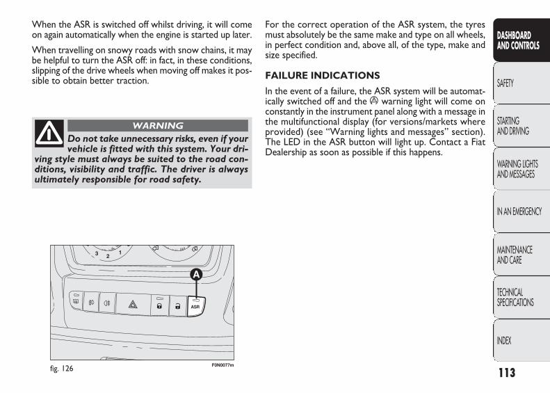
For the correct operation of the ASR system, the tyresmust absolutely be the same make and type on all wheels,in perfect condition and, above all, of the type, make andsize specified.
FAILURE INDICATIONS
In the event of a failure, the ASR system will be automat-ically switched off and the á warning light will come onconstantly in the instrument panel along with a message inthe multifunctional display (for versions/markets whereprovided) (see “Warning lights and messages” section).The LED in the ASR button will light up. Contact a FiatDealership as soon as possible if this happens.
When the ASR is switched off whilst driving, it will comeon again automatically when the engine is started up later.
When travelling on snowy roads with snow chains, it maybe helpful to turn the ASR off: in fact, in these conditions,slipping of the drive wheels when moving off makes it pos-sible to obtain better traction.
F0N0077mfig. 126 113
DASHBOARD AND CONTROLS
SAFETY
STARTING AND DRIVING
WARNING LIGHTSAND MESSAGES
IN AN EMERGENCY
MAINTENANCE AND CARE
TECHNICAL SPECIFICATIONS
INDEX
Do not take unnecessary risks, even if yourvehicle is fitted with this system. Your dri-
ving style must always be suited to the road con-ditions, visibility and traffic. The driver is alwaysultimately responsible for road safety.
WARNING
037-122 DUCATO LUM EN 11-02-2010 14:27 Pagina 113
EOBD SYSTEM
The EOBD system (European On Board Diagnosis) allowscontinuous diagnosis of emission-related components onthe vehicle.
It also alerts the driver, by turning on the Uwarning lighton the instrument panel (together with a relevant messagein the multifunction display, for versions/markets whereprovided) (see “Warning lights and messages” section),when these components are no longer in peak condition.
The goal of the system is to:
❒ keep the system efficiency under control;
❒ warn about increased emissions due to a vehicle mal-function;
❒ warn of the need to replace non-performing compo-nents.
The system also has a connector that can be interfacedwith appropriate equipment, which makes it possible toread the error codes stored in the control unit, togetherwith a series of specific parameters for engine operationand diagnosis. This check can also be carried out by trafficpolice.
IMPORTANT After eliminating the problem, to checkthe system completely, Fiat Dealerships run a bench testand, if necessary, road tests which may also call for a longjourney.
114
DASHBOARD AND CONTROLS
SAFETY
STARTING AND DRIVING
WARNING LIGHTSAND MESSAGES
IN AN EMERGENCY
MAINTENANCE AND CARE
TECHNICAL SPECIFICATIONS
INDEX
If, when the ignition key is turned to theMAR position, the U warning light eitherdoes not come on or, when driving, it comes
on constantly or flashing (along with a message inthe multidirection display, for versions/markets whereprovided) contact a Fiat Dealership as soon as pos-sible. The operation of the Uwarning light may bechecked by the traffic authorities using specific de-vices. Respect the regulations in force in the coun-try where you are driving.
037-122 DUCATO LUM EN 11-02-2010 14:27 Pagina 114
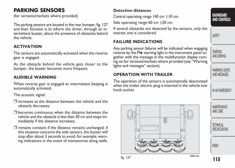
F0N0119mfig. 127
Detection distancesCentral operating range 140 cm ±10 cm.Side operating range 60 cm ±20 cm.If several obstacles are detected by the sensors, only thenearest one is considered.
FAILURE INDICATIONS
Any parking sensor failures will be indicated when engagingreverse by the t warning light in the instrument panel to-gether with the message in the multifunction display com-ing on for versions/markets where provided (see “Warninglights and messages” section).
OPERATION WITH TRAILER
The operation of the sensors is automatically deactivatedwhen the trailer electric plug is inserted in the vehicle towhook socket.
PARKING SENSORS (for versions/markets where provided)
The parking sensors are located in the rear bumper, fig. 127and their function is to inform the driver, through an in-termittent buzzer, about the presence of obstacles behindthe vehicle.
ACTIVATION
The sensors are automatically activated when the reversegear is engaged.
As the obstacle behind the vehicle gets closer to thebumper, the buzzer becomes more frequent.
AUDIBLE WARNING
When reverse gear is engaged an intermittent beeping isautomatically activated.
The acoustic signal:
❒ increases as the distance between the vehicle and theobstacle decreases;
❒ becomes continuous when the distance between thevehicle and the obstacle is less than 30 cm and stops im-mediately if the distance increases;
❒ remains constant if the distance remains unchanged; ifthis situation concerns the side sensors, the buzzer willstop after about 3 seconds to avoid, for example, warn-ing indications in the event of manoeuvres along walls.
115
DASHBOARD AND CONTROLS
SAFETY
STARTING AND DRIVING
WARNING LIGHTSAND MESSAGES
IN AN EMERGENCY
MAINTENANCE AND CARE
TECHNICAL SPECIFICATIONS
INDEX
037-122 DUCATO LUM EN 11-02-2010 14:27 Pagina 115
The sensors are automatically reactivated when the plugis removed.
IMPORTANT If you wish to leave the tow hook fittedwithout towing a trailer, it is advisable to contact a FiatDealership for the relevant system update operations be-cause the tow hook could be detected as an obstacle bythe central sensors.
When using special washing equipment such as high pres-sure jets or steam cleaning, clean the sensors very quicklykeeping the jet more than 10 cm away.
116
DASHBOARD AND CONTROLS
SAFETY
STARTING AND DRIVING
WARNING LIGHTSAND MESSAGES
IN AN EMERGENCY
MAINTENANCE AND CARE
TECHNICAL SPECIFICATIONS
INDEX
The driver always has ultimate responsi-bility for parking and other dangerous ma-
noeuvres. When parking, make sure that noone isstanding in the area, especially children or ani-mals. The parking sensors are designed to assistdrivers: in all cases, you must always pay the ut-most attention during potentially dangerous manoeuvres, even when carried out at low speed.
WARNING
The sensor must be clean of mud, dirt, snowor ice in order for the system to work. Becareful not to scratch or damage the sen-
sors while cleaning them. Avoid using dry, rough orhard cloths. The sensors should be washed withclean water, possibly with some car shampoo.
GENERAL WARNINGS
❒ When parking, take the utmost care over obstacles thatmay be above or below the sensors.
❒ Objects close to the vehicle, in certain circumstancesare not detected and could therefore cause damage tothe vehicle or be damaged.
The following conditions may influence the performanceof the parking sensor system:
❒ Reduced sensor sensitivity and a reduction in the park-ing assistance system performance could be due to thepresence on the surface of the sensor of: ice, snow,mud, thick paint;
037-122 DUCATO LUM EN 11-02-2010 14:27 Pagina 116

F0N0157mfig. 128
CAR RADIO (for versions/markets, where provided)
For radio operation, consult the Supplement attached tothis Owner Handbook.
SOUND SYSTEM CAPABILITY (for versions/markets where provided)
The system consists of:❒ sound system power cables;❒ front speaker connection cables;❒ aerial power cable;❒ 2 tweeters A on the front pillars (30 W max power
each), fig. 128;❒ 2 mid-woofers B in the front doors (165 mm diame-
ter, 40 W max power each) fig. 129;❒ radio aerial lead.
❒ The sensor may detect a non-existent obstacle (echonoise) due to mechanical noises, for example whenwashing the vehicle, in case of rain, strong wind, hail;
❒ The signals sent by the sensors can also be altered bythe presence of ultrasound devices (e.g. pneumaticbrake systems or pneumatic drills) near the vehicle;
❒ The performance of the parking assistance system mayalso be affected by the position of the sensors. For ex-ample by a change in the ride setting (caused by thewear of the shock absorbers, suspension), changing thetyres, overloading the vehicle and carrying out specifictuning operations that require the vehicle to be low-ered;
❒ Detection of obstacles in the upper part of the vehicle(particularly in the case of vans or chassis cabs) may notbe guaranteed because the system detects obstacles thatcould strike the lower part of the vehicle.
117
DASHBOARD AND CONTROLS
SAFETY
STARTING AND DRIVING
WARNING LIGHTSAND MESSAGES
IN AN EMERGENCY
MAINTENANCE AND CARE
TECHNICAL SPECIFICATIONS
INDEX
037-122 DUCATO LUM EN 11-02-2010 14:27 Pagina 117
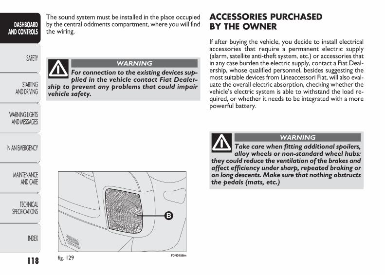
F0N0158mfig. 129
ACCESSORIES PURCHASED BY THE OWNER
If after buying the vehicle, you decide to install electricalaccessories that require a permanent electric supply(alarm, satellite anti-theft system, etc.) or accessories thatin any case burden the electric supply, contact a Fiat Deal-ership, whose qualified personnel, besides suggesting themost suitable devices from Lineaccessori Fiat, will also eval-uate the overall electric absorption, checking whether thevehicle’s electric system is able to withstand the load re-quired, or whether it needs to be integrated with a morepowerful battery.
The sound system must be installed in the place occupiedby the central oddments compartment, where you will findthe wiring.
118
DASHBOARD AND CONTROLS
SAFETY
STARTING AND DRIVING
WARNING LIGHTSAND MESSAGES
IN AN EMERGENCY
MAINTENANCE AND CARE
TECHNICAL SPECIFICATIONS
INDEX
For connection to the existing devices sup-plied in the vehicle contact Fiat Dealer-
ship to prevent any problems that could impairvehicle safety.
WARNING
Take care when fitting additional spoilers,alloy wheels or non-standard wheel hubs:
they could reduce the ventilation of the brakes andaffect efficiency under sharp, repeated braking oron long descents. Make sure that nothing obstructsthe pedals (mats, etc.)
WARNING
037-122 DUCATO LUM EN 11-02-2010 14:27 Pagina 118
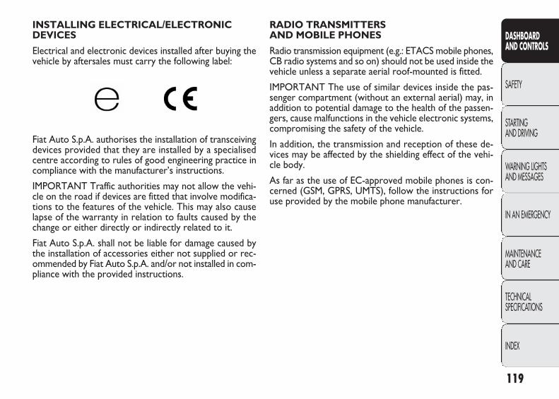
RADIO TRANSMITTERS AND MOBILE PHONES
Radio transmission equipment (e.g.: ETACS mobile phones,CB radio systems and so on) should not be used inside thevehicle unless a separate aerial roof-mounted is fitted.
IMPORTANT The use of similar devices inside the pas-senger compartment (without an external aerial) may, inaddition to potential damage to the health of the passen-gers, cause malfunctions in the vehicle electronic systems,compromising the safety of the vehicle.
In addition, the transmission and reception of these de-vices may be affected by the shielding effect of the vehi-cle body.
As far as the use of EC-approved mobile phones is con-cerned (GSM, GPRS, UMTS), follow the instructions foruse provided by the mobile phone manufacturer.
INSTALLING ELECTRICAL/ELECTRONIC DEVICES
Electrical and electronic devices installed after buying thevehicle by aftersales must carry the following label:
Fiat Auto S.p.A. authorises the installation of transceivingdevices provided that they are installed by a specialisedcentre according to rules of good engineering practice incompliance with the manufacturer’s instructions.
IMPORTANT Traffic authorities may not allow the vehi-cle on the road if devices are fitted that involve modifica-tions to the features of the vehicle. This may also causelapse of the warranty in relation to faults caused by thechange or either directly or indirectly related to it.
Fiat Auto S.p.A. shall not be liable for damage caused bythe installation of accessories either not supplied or rec-ommended by Fiat Auto S.p.A. and/or not installed in com-pliance with the provided instructions.
119
DASHBOARD AND CONTROLS
SAFETY
STARTING AND DRIVING
WARNING LIGHTSAND MESSAGES
IN AN EMERGENCY
MAINTENANCE AND CARE
TECHNICAL SPECIFICATIONS
INDEX
037-122 DUCATO LUM EN 11-02-2010 14:27 Pagina 119
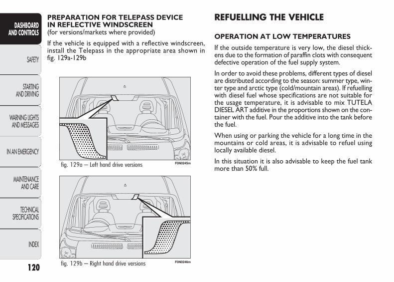
F0N0246mfig. 129b – Right hand drive versions
F0N0245mfig. 129a – Left hand drive versions
REFUELLING THE VEHICLE
OPERATION AT LOW TEMPERATURES
If the outside temperature is very low, the diesel thick-ens due to the formation of paraffin clots with consequentdefective operation of the fuel supply system.
In order to avoid these problems, different types of dieselare distributed according to the season: summer type, win-ter type and arctic type (cold/mountain areas). If refuellingwith diesel fuel whose specifications are not suitable forthe usage temperature, it is advisable to mix TUTELADIESEL ART additive in the proportions shown on the con-tainer with the fuel. Pour the additive into the tank beforethe fuel.
When using or parking the vehicle for a long time in themountains or cold areas, it is advisable to refuel using locally available diesel.
In this situation it is also advisable to keep the fuel tankmore than 50% full.
PREPARATION FOR TELEPASS DEVICE IN REFLECTIVE WINDSCREEN (for versions/markets where provided)
If the vehicle is equipped with a reflective windscreen,install the Telepass in the appropriate area shown in fig. 129a-129b
120
DASHBOARD AND CONTROLS
SAFETY
STARTING AND DRIVING
WARNING LIGHTSAND MESSAGES
IN AN EMERGENCY
MAINTENANCE AND CARE
TECHNICAL SPECIFICATIONS
INDEX
037-122 DUCATO LUM EN 11-02-2010 14:27 Pagina 120
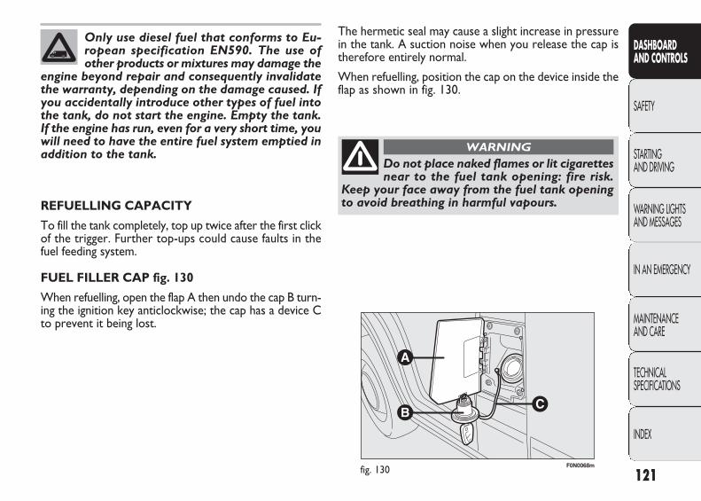
F0N0068mfig. 130
The hermetic seal may cause a slight increase in pressurein the tank. A suction noise when you release the cap istherefore entirely normal.
When refuelling, position the cap on the device inside theflap as shown in fig. 130.
REFUELLING CAPACITY
To fill the tank completely, top up twice after the first clickof the trigger. Further top-ups could cause faults in thefuel feeding system.
FUEL FILLER CAP fig. 130
When refuelling, open the flap A then undo the cap B turn-ing the ignition key anticlockwise; the cap has a device Cto prevent it being lost.
121
DASHBOARD AND CONTROLS
SAFETY
STARTING AND DRIVING
WARNING LIGHTSAND MESSAGES
IN AN EMERGENCY
MAINTENANCE AND CARE
TECHNICAL SPECIFICATIONS
INDEX
Only use diesel fuel that conforms to Eu-ropean specification EN590. The use ofother products or mixtures may damage the
engine beyond repair and consequently invalidatethe warranty, depending on the damage caused. Ifyou accidentally introduce other types of fuel intothe tank, do not start the engine. Empty the tank.If the engine has run, even for a very short time, youwill need to have the entire fuel system emptied inaddition to the tank.
Do not place naked flames or lit cigarettesnear to the fuel tank opening: fire risk.
Keep your face away from the fuel tank openingto avoid breathing in harmful vapours.
WARNING
037-122 DUCATO LUM EN 11-02-2010 14:27 Pagina 121
DIESEL PARTICULATE FILTER (DPF)
The Diesel Particulate Filter is a mechanical filter, inte-gral to the exhaust system, that physically traps particu-lates present in the exhaust gases of diesel engines.
It is needed to eliminate almost all particulates in compli-ance with current/future legislation.
During normal use of the vehicle, the engine control unitrecords a set of data (e.g. travel time, type of route, tem-peratures, etc.) and it will then calculate how much par-ticulate has been trapped by the filter.
Since this filter physically traps particulate, it should beregenerated (cleaned) at regular intervals by burning thecarbon particles.
The regeneration procedure is handled automatically bythe engine control unit according to the filter conditionsand vehicle use conditions.
During regeneration, the following may occur: a limited in-crease in the engine speed, activation of the fan, a limitedincrease in fumes and high temperatures at the exhaust.These are not faults; they do not impair vehicle perfor-mance or damage the environment.
If the dedicated message is displayed, refer to the “Warn-ing lights and messages” section.
PROTECTING THE ENVIRONMENT
The following devices are used for reducing diesel fuel en-gine emissions:
❒ oxidising catalytic converter;
❒ exhaust gas recirculation system (E.G.R.);
❒ diesel particulate filter (DPF).
122
DASHBOARD AND CONTROLS
SAFETY
STARTING AND DRIVING
WARNING LIGHTSAND MESSAGES
IN AN EMERGENCY
MAINTENANCE AND CARE
TECHNICAL SPECIFICATIONS
INDEX
The diesel particulate filter (DPF) reacheshigh temperatures during operation. There-
fore do not therefore park the vehicle on inflam-mable materials (grass, dry leaves, pine needles,etc.): fire hazard.
WARNING
The catalytic converter also reaches hightemperatures during normal operation.
Do not park the on grass, dry leaves, pine needlesor other flammable material: fire hazard.
WARNING
037-122 DUCATO LUM EN 11-02-2010 14:27 Pagina 122

F0N0069mfig. 131
Through the reel, the belt automatically adapts to the bodyof the passenger wearing it, allowing freedom of movement.
The reel may block when the vehicle is parked on a steepslope: this is perfectly normal. Furthermore, the reel mecha-nism locks the belt if it is pulled and in the event of suddenbraking, collisions and on high speed bends.
SAFETY BELTS
USING THE SEAT BELTS fig. 131
The belt should be worn keeping the chest straight andrested against the seat back.
To fasten the seat belts, hold the tongue A and insert it in-to the buckle B, until the locking click is heard.
On removal, if it jams, let it rewind for a short stretch,then pull it out again without jerking.
To unfasten the seat belts, press button C. Guide the seatbelt with your hand while it is rewinding, to prevent it fromtwisting.
123
DASHBOARD AND CONTROLS
SAFETY
STARTING AND DRIVING
WARNING LIGHTSAND MESSAGES
IN AN EMERGENCY
MAINTENANCE AND CARE
TECHNICAL SPECIFICATIONS
INDEX
SAFETY
Never press button C-fig. 131 when trav-elling.
WARNING
HEIGHT ADJUSTMENT fig. 132
The height of the seat belts must be ad-justed with the vehicle at a standstill.
WARNING
To adjust, use button A-fig. 132 to raise or lower handleB-fig. 132.
Always adjust the seat belt height to the passenger’s body:this precaution may considerably reduce the risk of in-jury in the event of a collision.
123-140 DUCATO LUM EN 11-02-2010 14:33 Pagina 123
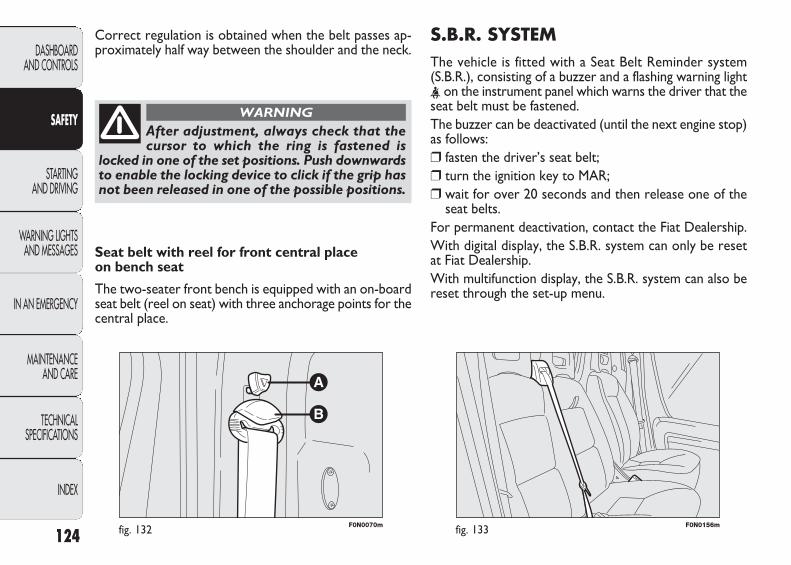
S.B.R. SYSTEMThe vehicle is fitted with a Seat Belt Reminder system(S.B.R.), consisting of a buzzer and a flashing warning light< on the instrument panel which warns the driver that theseat belt must be fastened. The buzzer can be deactivated (until the next engine stop)as follows:❒ fasten the driver’s seat belt; ❒ turn the ignition key to MAR;❒ wait for over 20 seconds and then release one of the
seat belts.For permanent deactivation, contact the Fiat Dealership.With digital display, the S.B.R. system can only be resetat Fiat Dealership.With multifunction display, the S.B.R. system can also bereset through the set-up menu.
F0N0070mfig. 132 F0N0156mfig. 133
Seat belt with reel for front central place on bench seat
The two-seater front bench is equipped with an on-boardseat belt (reel on seat) with three anchorage points for thecentral place.
Correct regulation is obtained when the belt passes ap-proximately half way between the shoulder and the neck.
124
DASHBOARD AND CONTROLS
SAFETY
STARTING AND DRIVING
WARNING LIGHTSAND MESSAGES
IN AN EMERGENCY
MAINTENANCE AND CARE
TECHNICAL SPECIFICATIONS
INDEX
After adjustment, always check that thecursor to which the ring is fastened is
locked in one of the set positions. Push downwardsto enable the locking device to click if the grip hasnot been released in one of the possible positions.
WARNING
123-140 DUCATO LUM EN 11-02-2010 14:33 Pagina 124
PRETENSIONERS
To increase the efficiency of the seat belts, the vehicle isfitted with pretensioners. These devices, in the event ofa violent crash, rewind the seat belts a few centimetres. Inthis way they ensure that the seat belt adheres perfectlyto the wearer before the restraining action begins.
The seat belt locks to indicate that the device has inter-vened; the seat belt cannot be drawn back up even whenguiding it manually.
IMPORTANT To obtain the highest degree of protectionfrom the action of the pretensioning device, wear the seatbelt keeping it firmly close to the chest and pelvis.
A slight amount of smoke may be detected during opera-tion of the pretensioners. This smoke is not harmful anddoes not indicate a fire.
The pretensioner does not require any maintenance orlubrication.
Anything that modifies its original conditions invalidates itsefficiency.
If unusual natural events (floods, sea storms, etc.) havecaused the device to be contaminated by water and mud,it must be replaced.
125
DASHBOARD AND CONTROLS
SAFETY
STARTING AND DRIVING
WARNING LIGHTSAND MESSAGES
IN AN EMERGENCY
MAINTENANCE AND CARE
TECHNICAL SPECIFICATIONS
INDEX
The pretensioner can only be used once.Contact a Fiat Dealership to have it re-
placed after is has been deployed. The device ex-piry date is shown on the plate in the glove com-partment: contact the FIAT Dealership when it’stime to replace the device.
WARNING
Operations which lead to knocks, vibrationsor localised heating (over 100°C for a max-imum of 6 hours) in the area around the
pretensioners may cause damage or trigger them.These devices are not affected by vibrations causedby irregularities of the road surface or low obsta-cles such as kerbs, etc. Contact a Fiat Dealershipfor any assistance.
LOAD LIMITERS
To increase passenger’s safety, the front seat belt reelscontain a load limiter which allows controlled sag in sucha way as to dose the force acting on the chest and shouldersduring the belt restraining action in case of front crash.
123-140 DUCATO LUM EN 11-02-2010 14:33 Pagina 125

F0N0121mfig. 135F0N0120mfig. 134126
DASHBOARD AND CONTROLS
SAFETY
STARTING AND DRIVING
WARNING LIGHTSAND MESSAGES
IN AN EMERGENCY
MAINTENANCE AND CARE
TECHNICAL SPECIFICATIONS
INDEX
GENERAL INSTRUCTIONS FOR USING THE SEAT BELTS
The driver is responsible for respecting (and ensuring thatall the other vehicle passengers also respect) the local lawsin force regarding the use of seat belts. Always fasten theseat belts before starting off.
Seat belts are also to be worn by expectant mothers: therisk of injury in the case of accident is greatly reduced forthem and the unborn child if they are wearing a seat belt.
Of course they must position the lower part of the belt verylow down so that it passes under the abdomen, see 134.
The belt must not be twisted. The upperpart must cross the shoulder and the chest
diagonally. The lower part must adhere to the hips fig. 135 not to the abdomen. Do not use devices(clips, clamps, etc.) that prevent the belts from be-ing snug to the passengers’ body.
WARNING
Maximum protection is obtained if thebackrest is kept straight: the passenger’s
back must lean against the backrest and the seatbelt must be tight on the chest and hips. Always fas-ten the seat belts on both the front and the rearseats. Travelling without seat belts fastened in-creases the risk of serious injuries or even death inthe event of a crash.
WARNING
123-140 DUCATO LUM EN 11-02-2010 14:33 Pagina 126

F0N0122mfig. 136 127
DASHBOARD AND CONTROLS
SAFETY
STARTING AND DRIVING
WARNING LIGHTSAND MESSAGES
IN AN EMERGENCY
MAINTENANCE AND CARE
TECHNICAL SPECIFICATIONS
INDEX
Under no circumstances should the seatbelt and pretensioner components be re-
moved or tampered with. All interventions mustbe performed by qualified and authorised per-sonnel only. Always go to a Fiat Dealership
WARNING
If the belt has been subjected to a heavystress, for example after an accident, it
should be changed completely together with theanchors, anchor fastening screws and the pre-tensioner. In fact, even if the belt has no visibledefects, it could have lost its resilience.
WARNING
Each seat belt must be worn by one per-son only; do not carry children on your
lap with one seat belt protecting both. In gen-eral, do not place any objects between the per-son and belt.
WARNING
HOW TO KEEP THE SEAT BELTS ALWAYSIN EFFICIENT CONDITIONS
Observe the following precautions for correct seat beltmaintenance:
❒ always use the belts with the tap well stretched andnever twisted; make sure that it is free to run withoutimpediments;
❒ replace the belt after an accident of a certain severityeven if it does not appear damaged. Always replace thebelt if the pretensioners were deployed;
❒ to clean the belt, wash by hand with water and mildsoap, rinse and leave to dry in the shade. Do not usestrong detergents, bleach, paints or any other substancewhich could damage the belt fibres;
❒ prevent the reels from getting wet: their correct op-eration is only guaranteed if water does not get inside;
❒ replace the seat belt when showing significant wear orcut signs.
123-140 DUCATO LUM EN 11-02-2010 14:33 Pagina 127
Over 1.50 m in height, from the point of view of restraintsystems, children are considered as adults and wear theseat belts normally.
CARRYING CHILDREN SAFELY
For optimum protection in the event of a crash, all pas-sengers must be seated and wearing adequate restraintsystems. This is even more important for children. Thisprescription is compulsory in all EC countries accordingto EC Directive 2003/20/EC.
A child’s head is larger and heavier in proportion to itsbody and the child’s muscular and bone structures are notfully developed. For this reason, they require restraint sys-tems which are different from those used by adults to pro-tect them in the event of an accident. The results of re-search in relation to the best protection for children is illustrated in European Regulation CEE-R44, which dividesthe restraint systems into five groups in addition to mak-ing their use compulsory:
Group 0 up to 10 kg of weight
Group 0+ up to 13 kg of weight
Group 1 9 – 18 kg of weight
Group 2 15 – 25 kg of weight
Group 3 22 – 36 kg of weight
As it may be noted, the groups overlap partly and in fact,in commerce it is possible to find devices that cover morethan one weight group. All restraint devices must bear thecertification data, together with the control brand, on asolidly fixed label which must absolutely never be removed.
128
DASHBOARD AND CONTROLS
SAFETY
STARTING AND DRIVING
WARNING LIGHTSAND MESSAGES
IN AN EMERGENCY
MAINTENANCE AND CARE
TECHNICAL SPECIFICATIONS
INDEX
Do not place a cradle seat facing back-wards on the front seat if the passenger
side airbag is on. Deployment of the airbag in anaccident could cause fatal injuries to the baby re-gardless of the severity of the collision. It is ad-visable to carry children in dedicated child seatson the rear seat, which is the most protected po-sition in the event of an accident.
WARNING
SERIOUS HAZARD Should it be absolute-ly necessary to carry a child on the frontseat in a cradle seat facing away from thedirection of travel, the passenger’s front airbag and Side Bag (for versions/markets
where provided) should be deactivated by using theSet-Up Menu. Deactivation can be verified bychecking the F warning light in the instrument panel. Move the passenger’s seat as far back as pos-sible to avoid contact between the child seat andthe dashboard.
WARNING
123-140 DUCATO LUM EN 11-02-2010 14:33 Pagina 128
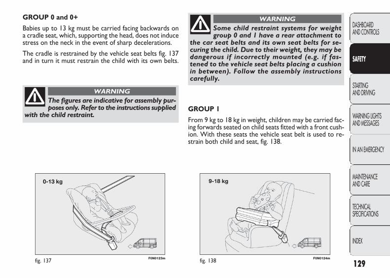
F0N0123mfig. 137 129
DASHBOARD AND CONTROLS
SAFETY
STARTING AND DRIVING
WARNING LIGHTSAND MESSAGES
IN AN EMERGENCY
MAINTENANCE AND CARE
TECHNICAL SPECIFICATIONS
INDEX
GROUP 0 and 0+
Babies up to 13 kg must be carried facing backwards on a cradle seat, which, supporting the head, does not inducestress on the neck in the event of sharp decelerations.
The cradle is restrained by the vehicle seat belts fig. 137and in turn it must restrain the child with its own belts.
The figures are indicative for assembly pur-poses only. Refer to the instructions supplied
with the child restraint.
WARNING
F0N0124mfig. 138
GROUP 1
From 9 kg to 18 kg in weight, children may be carried fac-ing forwards seated on child seats fitted with a front cush-ion. With these seats the vehicle seat belt is used to re-strain both child and seat, fig. 138.
Some child restraint systems for weightgroup 0 and 1 have a rear attachment to
the car seat belts and its own seat belts for se-curing the child. Due to their weight, they may bedangerous if incorrectly mounted (e.g. if fas-tened to the vehicle seat belts placing a cushionin between). Follow the assembly instructionscarefully.
WARNING
123-140 DUCATO LUM EN 11-02-2010 14:33 Pagina 129
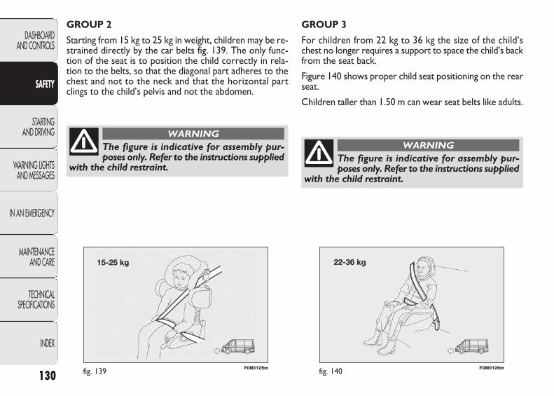
F0N0125mfig. 139 F0M0126mfig. 140
GROUP 3
For children from 22 kg to 36 kg the size of the child’schest no longer requires a support to space the child’s backfrom the seat back.
Figure 140 shows proper child seat positioning on the rearseat.
Children taller than 1.50 m can wear seat belts like adults.
130
DASHBOARD AND CONTROLS
SAFETY
STARTING AND DRIVING
WARNING LIGHTSAND MESSAGES
IN AN EMERGENCY
MAINTENANCE AND CARE
TECHNICAL SPECIFICATIONS
INDEX
GROUP 2
Starting from 15 kg to 25 kg in weight, children may be re-strained directly by the car belts fig. 139. The only func-tion of the seat is to position the child correctly in rela-tion to the belts, so that the diagonal part adheres to thechest and not to the neck and that the horizontal partclings to the child’s pelvis and not the abdomen.
The figure is indicative for assembly pur-poses only. Refer to the instructions supplied
with the child restraint.
WARNING
The figure is indicative for assembly pur-poses only. Refer to the instructions supplied
with the child restraint.
WARNING
123-140 DUCATO LUM EN 11-02-2010 14:33 Pagina 130
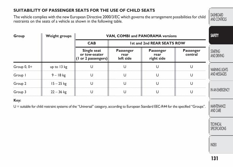
131
DASHBOARD AND CONTROLS
SAFETY
STARTING AND DRIVING
WARNING LIGHTSAND MESSAGES
IN AN EMERGENCY
MAINTENANCE AND CARE
TECHNICAL SPECIFICATIONS
INDEX
SUITABILITY OF PASSENGER SEATS FOR THE USE OF CHILD SEATS
The vehicle complies with the new European Directive 2000/3/EC which governs the arrangement possibilities for childrestraints on the seats of a vehicle as shown in the following table.
Group Weight groups VAN, COMBI and PANORAMA versions
CAB 1st and 2nd REAR SEATS ROW
Single seat Passenger Passenger Passenger or tow-seater rear rear central
(1 or 2 passengers) left side right side
Group 0, 0+ up to 13 kg U U U U
Group 1 9 – 18 kg U U U U
Group 2 15 – 25 kg U U U U
Group 3 22 – 36 kg U U U U
Key:
U = suitable for child restraint systems of the “Universal” category, according to European Standard EEC-R44 for the specified “Groups”.
123-140 DUCATO LUM EN 11-02-2010 14:33 Pagina 131
Below is a summary of the rules of safety to be followed for carrying children:
1) The recommended position for installing child seats ison the rear seat, as it is the most protected area in theevent of a crash.
2) If the passenger’s air bag is deactivated always checkthe amber warning light on the control panel to make surethat it has actually been deactivated.
3) Carefully follow the instructions supplied with the childrestraint system which are mandatory by law. Keep the in-structions in the vehicle along with the other papers andthis handbook. Do not use second-hand child seats with-out instructions.
4) Always check the seat belt is well fastened by pullingthe webbing.
5) Only one child is to be strapped into each retainingsystem; never carry two children using one child seat.
6) Always check the seat belts do not fit around the child’sthroat.
7) While travelling, do not let the child sit incorrectly orrelease the belts.
8) Never carry children on your lap, even newborns. No-one, however strong, can hold a child in the case of anaccident.
9) In case of an accident, replace the child’s seat with a new one.
132
DASHBOARD AND CONTROLS
SAFETY
STARTING AND DRIVING
WARNING LIGHTSAND MESSAGES
IN AN EMERGENCY
MAINTENANCE AND CARE
TECHNICAL SPECIFICATIONS
INDEX
Do not place a cradle seat facing back-wards on the front seat if the passenger
side airbag is on. Deployment of the airbag in anaccident could cause fatal injuries to the baby re-gardless of the severity of the collision. It is ad-visable to carry children in an appropriate re-straint system on the rear seat which is the mostprotected position in the event of an accident.
WARNING
“UNIVERSAL ISOFIX” CHILD RESTRAINT ASSEMBLY SETUP
Provision has been made on the vehicle to fit a UniversalIsofix child restraint system, a new European standardisedsystem for carrying children safely. An example of a childseat is shown in fig. 141. Due to its different anchoring sys-tem, the Universal Isofix child’s seat shall be anchored tothe proper lower metal rings A-fig. 142, set between rearseat back and cushion. The upper belt (provided with thechild’s seat) must be then secured to ring B-fig. 143 seton the rear at child’s seat level. It is possible to mount atthe same time both the traditional restraint system andthe “Universal Isofix” one.
Remember that in case of Universal Isofix child’s seat, youcan only use all those seats approved with the marking EKE R44/03 “Universal Isofix”.
123-140 DUCATO LUM EN 11-02-2010 14:33 Pagina 132

F0N0236mfig. 141 F0N0235mfig. 143
F0N0234mfig. 142
133
DASHBOARD AND CONTROLS
SAFETY
STARTING AND DRIVING
WARNING LIGHTSAND MESSAGES
IN AN EMERGENCY
MAINTENANCE AND CARE
TECHNICAL SPECIFICATIONS
INDEX
Fit the child seat when the vehicle is sta-tionary. The child seat is correctly an-
chored to the brackets when you hear the click.
WARNING
Follow the instructions for assembly, dis-assembly and positioning that the manu-
facturer must supply with the child seat.
WARNING
123-140 DUCATO LUM EN 11-02-2010 14:33 Pagina 133

134
DASHBOARD AND CONTROLS
SAFETY
STARTING AND DRIVING
WARNING LIGHTSAND MESSAGES
IN AN EMERGENCY
MAINTENANCE AND CARE
TECHNICAL SPECIFICATIONS
INDEX
PASSENGER SEAT COMPLIANCE WITH REGULATIONS ON UNIVERSAL ISOFIX CHILD SEAT USE
The table below shows the different installation possibilities of Isofix restraint systems on seats fitted with UniversalIsofix fasteners in compliance with European standard ECE 16.
Weight group Direction Class Isofix positions seat Isofix size rear side 1st row
PANORAMA COMBI
Portable cradle
Group 0 0 to 10 kg
Group 0+ up to 13 kg
Group I from 9up to 18 kg
Facing forwards
Facing forwards
Facing forwards
Facing forwards
Facing forwards
Facing forwards
Facing forwards
Facing forwards
Facing forwards
Facing forwards
F
G
E
E
D
C
D
C
B1
A
IUF
IUF
IUF
IUF
IUF
IUF
IUF
IUF(*)
IUF
IUF
IUF
IUF
IUF
IUF
IUF
IUF(*)
IUF
IUF(*)
IUF
IUF
(*) Not with two-seater front bench.
IUF: suitable for Isofix child restraint systems to be set facing forwards, universal class (fitted with third upper fastener), approvedfor the weight group.
123-140 DUCATO LUM EN 11-02-2010 14:33 Pagina 134
The front air bags may not be activated in the following sit-uations:
❒ during collisions against highly deformable objects thatdo not affect the vehicle front surface (e.g. bumper col-lision against guard rail, heaps of gravel, etc.);
❒ jamming of the vehicle underneath other vehicles orprotective barriers (e.g. underneath a truck or a guardrail); in this case, the bags would offer no additional pro-tection with respect to the seat belt and their deploy-ment is unnecessary. No deployment in such cases isconsequently not the sign of a fault.
FRONT AIRBAGS
The vehicle is provided with front airbags for the driverand the passenger.
The front driver/passenger air bags have been designed toprotect the occupants in the event of head-on crashes ofmedium-high severity, by placing the cushion between theoccupant and the steering wheel or dashboard.
Front air bags are designed to protect car’s occupants inhead-on crashes and therefore non-activation in othertypes of collisions (side collisions, rear shunts, roll-overs,etc.) is not a system malfunction.
An electronic control unit causes the bag to inflate in theevent of a head-on crash. The bag will inflate instantaneous-ly placing itself between the front occupant’s body and thestructures which could cause injury. It will deflate immedi-ately afterwards.
Driver and passenger front airbags are not a replacementof but complementary to the belts, which you are recom-mended to always wear, as specified by law in Europe andmost non-European countries.
The volume of front air bags at max. inflation fills most ofthe space between the steering wheel and the driver andbetween the dashboard and the passenger.
In the event of an impact, someone not wearing a seat beltwill move forward and come into contact with the bagwhich is still in the opening stage. The protection offeredby the bag is reduced in such a case.
135
DASHBOARD AND CONTROLS
SAFETY
STARTING AND DRIVING
WARNING LIGHTSAND MESSAGES
IN AN EMERGENCY
MAINTENANCE AND CARE
TECHNICAL SPECIFICATIONS
INDEX
Do not apply stickers or other objects onthe steering wheel, passenger side airbag
cover or side upholstery on roof. Do not place ob-jects on the passenger side dashboard becausethese could interfere with the correct opening ofthe airbag (e.g. mobile phones) and cause severeinjury to occupants.
WARNING
The airbags are not deployed in the event of collisions oflow severity (for which the withholding action of the seatbelts is sufficient). For this reason, the seat belt must beworn at all times. In the case of side collisions, the seatbelts hold occupants in the correct position and preventbeing thrown out of the car by a very violent collision.
123-140 DUCATO LUM EN 11-02-2010 14:33 Pagina 135

F0N0072mfig. 145
F0N0324mfig. 144
PASSENGER’S FRONT AIR BAG fig. 145(for versions/markets where provided)
This consists of an instant inflating bag contained in a spe-cial recess in the dashboard: this bag has a larger volumethan that of the driver’s.
DRIVER’S FRONT AIR BAG fig. 144
This consists of an instant inflating bag contained in a spe-cial recess in the centre of the steering wheel.
136
DASHBOARD AND CONTROLS
SAFETY
STARTING AND DRIVING
WARNING LIGHTSAND MESSAGES
IN AN EMERGENCY
MAINTENANCE AND CARE
TECHNICAL SPECIFICATIONS
INDEX
SEVERE DANGER: do not arrange cradlechild restraints facing backwards if the pas-senger’s airbag is on. Deployment of theairbag in an accident could cause fatal in-juries to the baby. Always deactivate the
passenger air bag when placing a child seat on thefront seat. Move the passenger’s seat as far backas possible to avoid contact between the cradle andthe dashboard. Although this is not mandatory bylaw, the air bag should be immediately reactivatedwhen children are no longer carried to ensure bet-ter protection for adults.
WARNING
123-140 DUCATO LUM EN 11-02-2010 14:33 Pagina 136

SIDE AIRBAGS The vehicle is fitted with front side bags for driver and pas-senger (for versions/markets where provided) for pro-tecting the chest and window bags (for versions/marketswhere provided) for protecting front and rear passengers’head.
Side bags (for versions/markets where provided) protectvehicle occupants from side crashes of medium-highseverity, by placing the bag between the occupant andthe internal parts of the side structure of the vehicle.
Non-activation of side bags in other types of collisions(front collisions, rear shunts, roll-overs, etc...) is not a sys-tem malfunction.
An electronic control unit causes the bags to inflate inthe event of a frontal crash. The bags inflate instantaneouslyplacing themselves between the front occupant’s body andthe structures which could cause injury. They deflate im-mediately afterwards.
Side bags (for versions/markets where provided) are nota replacement of but complementary to the belts, whichyou are recommended to always wear, as specified by lawin Europe and most non-European countries.
FRONT SIDE BAGS – CHEST AND PELVIS ZONE fig. 146 (for versions/markets where provided)
Front side bags are housed in the seat back rests, they con-sist of an instantly inflating bag designed to increase pro-tection of the occupants’ chest and pelvis zone in the eventof a side crash of medium-high severity.
MANUAL DEACTIVATION OF PASSENGER’S FRONT AIR BAG AND SIDE BAG CHEST PROTECTION (for versions/markets where provided)
Whenever a child needs to be carried on the front seat,the passenger’s front airbag and the Side Bag chest pro-tection (for versions/markets where provided) must bedeactivated.
The instrument panel warning light F will stay on glow-ing steadily until reactivating the passenger’s front air bagand the Side Bag chest protection (for versions/marketswhere provided).
137
DASHBOARD AND CONTROLS
SAFETY
STARTING AND DRIVING
WARNING LIGHTSAND MESSAGES
IN AN EMERGENCY
MAINTENANCE AND CARE
TECHNICAL SPECIFICATIONS
INDEX
To deactivate the passenger’s front air bagand the Side Bag chest protection (for ver-
sions/markets where provided) , refer to paragraphs“Digital display” and “Multifunction display” insection “Dashboard and controls”.
WARNING
123-140 DUCATO LUM EN 11-02-2010 14:33 Pagina 137

F0N0140mfig. 146 F0N0133mfig. 147
IMPORTANT A small amount of dust will be releasedwhen the airbags are deployed. The dust is not harmfuland does not indicate the beginning of a fire. Furthermore,the surface of the deployed bag and the interior of thevehicle may be covered with residual dust. This dust canirritate skin and eyes. Wash with mild soap and water inthe event of exposure.
The expiry date of the explosive charge and the clock wireare shown on a specific label contained in the oddmentcompartment. Contact a Fiat Dealership to have the de-vices replaced when the expiry date approaches.
IMPORTANT Should an accident occur in which any ofthe safety devices is activated, take the car to a Fiat Deal-ership to have the devices activated replaced and to havethe system checked.
Every control, repair and replacement operations con-cerning the air bags must only be carried out c/o FiatDealership.
SIDE WINDOW BAGS – HEAD PROTECTION fig. 147 (for versions/markets where provided)
They consist of two curtain bags, one on the right andthe other on the left side of the vehicle, located behind the side coverings of the roof and covered by proper finishing. Window bags have been designed for protecting the headof front and rear occupants in the event of side crash,thanks to the wide bag inflation surface.IMPORTANT In the event of side crash, you can obtainthe best protection by the system keeping a correct po-sition on the seat, allowing thus a correct window bagunfolding.IMPORTANT The front air bags and/or side bags may bedeployed if the vehicle is subject to heavy knocks or acci-dents involving the underbody area, such as for exampleviolent shocks, against steps, kerbs or low obstacles, ve-hicle falling into big pot holes or depressions in the road.
138
DASHBOARD AND CONTROLS
SAFETY
STARTING AND DRIVING
WARNING LIGHTSAND MESSAGES
IN AN EMERGENCY
MAINTENANCE AND CARE
TECHNICAL SPECIFICATIONS
INDEX
123-140 DUCATO LUM EN 11-02-2010 14:33 Pagina 138

GENERAL WARNINGSIf you are having the vehicle scrapped, have the air bag sys-tem deactivated at a Fiat Dealership first. If the vehiclechanges ownership, the new owner must be informed ofthe method of use of air bags and the above warnings andalso be given this “Owner’s Handbook”.
IMPORTANT Pretensioners, front airbags and front sidebags are deployed according to different logics on the ba-sic of the type of collision. Non-deployment of one of thedevices does not necessarily indicate a system malfunction.
139
DASHBOARD AND CONTROLS
SAFETY
STARTING AND DRIVING
WARNING LIGHTSAND MESSAGES
IN AN EMERGENCY
MAINTENANCE AND CARE
TECHNICAL SPECIFICATIONS
INDEX
Never rest head, arms and elbows on thedoor, on the windows and in the window
bag area to prevent possible injuries during infla-tion phase.
WARNING
Never lean head, arms and elbows out ofwindow.
WARNING
If when turning the key to MAR the warn-ing light ¬ does not turn on or if it stays
on when travelling (together with the message onthe multifunction display, for versions/markets,where provided) there could be a failure in safetysystems; in this event air bags or pretensionerscould not trigger in case of impact or, in a minornumber of cases, they could trigger accidentally.Contact Fiat Dealership immediately to have thesystem checked before driving off.
WARNING
Do not cover the front and rear seat back-rest with upholstery or seat covers that
hinder deployment of the side bag.
WARNING
Do not travel with objects in your lap, infront of your chest, or keeping between
your lips pipes, pencils, etc.. In the event of crashwith airbag activation, you may be seriously in-jured.
WARNING
123-140 DUCATO LUM EN 11-02-2010 14:33 Pagina 139

140
DASHBOARD AND CONTROLS
SAFETY
STARTING AND DRIVING
WARNING LIGHTSAND MESSAGES
IN AN EMERGENCY
MAINTENANCE AND CARE
TECHNICAL SPECIFICATIONS
INDEX
With ignition key inserted, on MAR, evenif the engine is off, the air bags can acti-
vate also with the vehicle stopped, if it is hit byanother vehicle. For this reason, children must nev-er sit on the front seat, even if the vehicle is notmoving. On the other hand, whenever the key ispositioned on STOP, the safety devices (airbagsor pretensioners) do not deploy after a collision.In this case non-deployment of these devices doesnot indicate a system malfunction.
WARNING
If the vehicle has been subject to theft ora theft attempt or if it has been affected
by vandalism, flooding or inundation, have the airbag system checked at a Fiat Dealership.
WARNING
Turning the ignition key to MAR, thewarning light F (airbag on passenger’s
side enabled) goes on and flashes for a few sec-onds, thus reminding the passenger that the airbagon his/her side will deploy in the event of a colli-sion. After this time, the light goes off.
WARNING
Do not wash the car seats with water orpressurised steam (both by hand or at au-
tomatic washing stations).
WARNING
The front airbag is deployed in the eventof collisions having a more severe nature
than those required to activate the pretensioners.For collisions in the range between the two acti-vation thresholds, the fact that only the preten-sioners activate is normal.
WARNING
Always drive keeping your hands on thesteering wheel crown so that, in the event
of airbag activation, it can inflate without findingobstacles. Do not drive with your body bent for-ward. Keep the backrest in straight position, rest-ing correctly your back on it.
WARNING
Do not hook rigid objects to cloth hangersand to the support handles.
The air bag does not replace seat belts but increasestheir efficiency. Furthermore, since front airbags arenot deployed in low speed collisions, side collisions,rear-end shunts or roll-overs, the occupants are on-ly protected by the seat belts which must be fas-tened at all times.
WARNING
123-140 DUCATO LUM EN 11-02-2010 14:33 Pagina 140
PROCEDURE Proceed as follows:❒ apply the handbrake;❒ put the gear lever into neutral;❒ turn the ignition key to MAR: the warning lights m andY on the instrument panel will turn on;
❒ Wait for the warning lights Y and m to turn off. Thehotter the engine is, the quicker this will happen;
❒ press the clutch pedal all the way down without touch-ing the accelerator;
❒ turn the ignition key to AVV as soon as the warning lightm turns off. Waiting too long will waste the workdone by the glow plugs. Release the key as soon as theengine starts.
If the engine does not start at the first attempt, returnthe ignition key to STOP before repeating starting.
STARTING THE ENGINE
The vehicle is fitted with an electronic engine lock device:if the engine fails to start, see the paragraph “The FiatCODE system” in section “Dashboard and controls”.
141
DASHBOARD AND CONTROLS
SAFETY
STARTING AND DRIVING
WARNING LIGHTSAND MESSAGES
IN AN EMERGENCY
MAINTENANCE AND CARE
TECHNICAL SPECIFICATIONS
INDEX
STARTING AND DRIVING
It is dangerous to let the engine run in en-closed spaces. The engine depletes the
oxygen and discharges carbon dioxide, carbonmonoxide and other toxic gases.
WARNING
In the first period of use, we recommendavoiding excessive stress for the car (for in-stance excessive accelerations, extended
travel at maximum speed, sudden braking etc.).
When the engine is switched off neverleave the key into the ignition switch toprevent pointless current absorption from
draining the battery.
Remember that the brake booster andpower steering are not operational until
the engine has been started, therefore much ef-fort than usual is required on the brake pedal andsteering wheel.
WARNING
141-154 DUCATO LUM EN 12-02-2010 8:52 Pagina 141
If, when the ignition key is at MAR the warning light Yremains on together with warning light m, turn the keyto STOP and then back to MAR; if the warning lights re-main on, try with the other keys provided with the car.
IMPORTANT If the instrument panel warning light Ystays on glowing steadily, contact immediately Fiat Deal-ership.
IMPORTANT Never leave the ignition key to MAR whenthe engine is off.
142
DASHBOARD AND CONTROLS
SAFETY
STARTING AND DRIVING
WARNING LIGHTSAND MESSAGES
IN AN EMERGENCY
MAINTENANCE AND CARE
TECHNICAL SPECIFICATIONS
INDEX
Warning light m will blink for 60 secondsafter starting or during prolonged crank-ing to indicate a fault to the glow plug heat-
ing system. Use the vehicle normally if the enginestarts, but contact the Fiat Dealership as soon aspossible.
Remember that the servo brake and pow-er steering are not operational until the en-gine has been started, therefore more ef-
fort than usual is required on the brake pedal andsteering wheel.
Avoid jump starting the engine by pushing,towing or driving downhill. This could causea flow of fuel into the catalytic converter
and damage it beyond repair.
HOW TO WARM UP THE ENGINE AFTER ITHAS JUST STARTED
Proceed as follows:
❒ drive off slowly, letting the engine turn at medium speed.Do not accelerate abruptly;
❒ do not demand maximum performance for the first fewkilometres. Wait until the engine coolant gauge startsmoving.
STOPPING THE ENGINE
Turn the ignition key to STOP while the engine is idling.
IMPORTANT After a taxing drive, you should allow theengine to “catch its breath” before turning it off by lettingit idle to allow the temperature in the engine compartmentto fall.
A quick burst on the accelerator beforeturning off the engine serves absolutely nopractical purpose, it wastes fuel and is
damaging especially to turbocharged engines.
141-154 DUCATO LUM EN 12-02-2010 8:52 Pagina 142
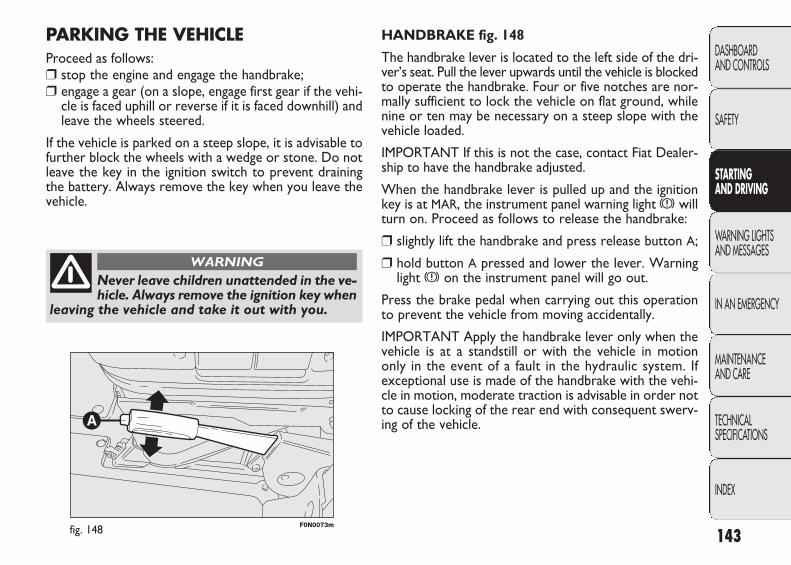
F0N0073mfig. 148
HANDBRAKE fig. 148
The handbrake lever is located to the left side of the dri-ver’s seat. Pull the lever upwards until the vehicle is blockedto operate the handbrake. Four or five notches are nor-mally sufficient to lock the vehicle on flat ground, whilenine or ten may be necessary on a steep slope with thevehicle loaded.
IMPORTANT If this is not the case, contact Fiat Dealer-ship to have the handbrake adjusted.
When the handbrake lever is pulled up and the ignitionkey is at MAR, the instrument panel warning light x willturn on. Proceed as follows to release the handbrake:
❒ slightly lift the handbrake and press release button A;
❒ hold button A pressed and lower the lever. Warninglight x on the instrument panel will go out.
Press the brake pedal when carrying out this operationto prevent the vehicle from moving accidentally.
IMPORTANT Apply the handbrake lever only when thevehicle is at a standstill or with the vehicle in motiononly in the event of a fault in the hydraulic system. Ifexceptional use is made of the handbrake with the vehi-cle in motion, moderate traction is advisable in order notto cause locking of the rear end with consequent swerv-ing of the vehicle.
PARKING THE VEHICLEProceed as follows:❒ stop the engine and engage the handbrake;❒ engage a gear (on a slope, engage first gear if the vehi-
cle is faced uphill or reverse if it is faced downhill) andleave the wheels steered.
If the vehicle is parked on a steep slope, it is advisable tofurther block the wheels with a wedge or stone. Do notleave the key in the ignition switch to prevent drainingthe battery. Always remove the key when you leave thevehicle.
143
DASHBOARD AND CONTROLS
SAFETY
STARTING AND DRIVING
WARNING LIGHTSAND MESSAGES
IN AN EMERGENCY
MAINTENANCE AND CARE
TECHNICAL SPECIFICATIONS
INDEX
Never leave children unattended in the ve-hicle. Always remove the ignition key when
leaving the vehicle and take it out with you.
WARNING
141-154 DUCATO LUM EN 12-02-2010 8:52 Pagina 143

F0N0074mfig. 149
USING THE MANUAL GEARBOX
To engage the gears, press the clutch pedal fully and shiftthe gear lever into one of the required positions (the di-agram is shown on the knob, fig. 149).
To engage 6th gear (where provided), operate the leverby pressing it towards the right in order to avoid engag-ing 4th gear by mistake. The same applies to the shift from6th to 5th gear.
IMPORTANT Reverse may only be engaged when the ve-hicle is at a standstill. With the engine running, wait forat least 2 seconds with the clutch pedal fully pressed be-fore engaging reverse to prevent damage to the gears andgrating.
To engage reverse R from neutral, proceed as follows:raise ring A under the knob and at the same time movethe gear lever to the right and then backwards.
144
DASHBOARD AND CONTROLS
SAFETY
STARTING AND DRIVING
WARNING LIGHTSAND MESSAGES
IN AN EMERGENCY
MAINTENANCE AND CARE
TECHNICAL SPECIFICATIONS
INDEX
Press the clutch pedal fully to changegears correctly. For this reason, there must
be no obstacles on the floor under the pedals: en-sure that rubber mats (if any) are correctly po-sitioned, not interfering with the pedals.
WARNING
Do not drive with your hand resting on thegear lever, because this pressure, even iflight, over time can wear out the gearbox
inner components.
141-154 DUCATO LUM EN 12-02-2010 8:52 Pagina 144
IMPORTANT For versions with right and left side flaps,it is advisable to reposition the release lever in the closedposition before lowering the sides.
LOAD ADVICE
The Fiat Ducato version used by you has been designedand type approved on the basis of certain maximumweights (see “Weights” table in the “Technical Data” sec-tion): kerb weight, payload, total weight, maximum weighton front axle, maximum weight on rear axle, towableweight.
145
DASHBOARD AND CONTROLS
SAFETY
STARTING AND DRIVING
WARNING LIGHTSAND MESSAGES
IN AN EMERGENCY
MAINTENANCE AND CARE
TECHNICAL SPECIFICATIONS
INDEX
Each of these must be strictly observedand MUST NEVER BE EXCEEDED in any
case. In particular, ensure that you never exceedthe maximum permitted weights on the front andrear axles when arranging the load on the vehicle(particularly if the vehicle is equipped with a spe-cific version).
WARNING
IMPORTANT The maximum permitted load on the floorfastenings is 500 kg; the maximum permitted load on theside panel is 150 kg.
Irregular trajectories and abrupt brakingmay cause sudden movements of the load
with consequent situations of hazard for the dri-ver and passengers: before setting off, secure theload tightly using the appropriate hooks on thefloor and use steel cables, ropes or chains strongenough to hold the items to be secured.
WARNING
If a vehicle is parked on a very steep gra-dient or with a side gradient, opening the
rear door or side door could cause any unsecureditems to emerge suddenly.
WARNING
141-154 DUCATO LUM EN 12-02-2010 8:52 Pagina 145

CONTAINING RUNNING COSTS
Here are some suggestions which may help you to keepthe running costs of your vehicle down and lower theamount of toxic emissions released into the atmosphere.
GENERAL CONSIDERATIONS
Vehicle maintenance
Have checks and adjustments carried out in accordancewith the “Scheduled Maintenance Plan”.
Tyres
Check the pressure of the tyres routinely at an intervalof no more than 4 weeks: if the pressure is too low, con-sumption levels increase as resistance to rolling is higher.
Unnecessary loads
Do not travel with an overloaded bonnet. The weight ofthe vehicle (especially when driving in town) and its geom-etry greatly affect fuel consumption and stability.
Roof rack/ski rack
Remove the roof rack or the ski rack from the roof afteruse. These accessories decrease aerodynamic penetra-tion of the vehicle and have a negative effect on fuel con-sumption. It is better to use a trailer, particularly fortransporting bulky objects.
In addition to these general precautions, some simple pre-cautions can improve driving safety, travelling comfort andvehicle durability:
❒ distribute the load evenly over the floor: if it is neces-sary to concentrate it in a single area, choose an areamid-way between both axles;
❒ remember that the lower the load, the lower the ve-hicle centre of gravity, making for a safer drive: there-fore always position the heaviest goods lower down;
❒ lastly, remember that the vehicle’s dynamic behaviouris affected by the weight transported: in particular, thestopping distances are longer, particularly at high speed.
146
DASHBOARD AND CONTROLS
SAFETY
STARTING AND DRIVING
WARNING LIGHTSAND MESSAGES
IN AN EMERGENCY
MAINTENANCE AND CARE
TECHNICAL SPECIFICATIONS
INDEX
If you wish to carry petrol in a reservetank, observe the legal restrictions and on-
ly use a tank that is type approved and properlysecured to the load anchorage eyebolts. Howev-er, the risks in case of collision increase.
WARNING
141-154 DUCATO LUM EN 12-02-2010 8:52 Pagina 146

Unnecessary actions
Avoid revving up when starting at traffic lights or beforestopping the engine. The latter action, like doubling theclutch, is unnecessary and causes increase of consumptionand pollution.
Gear selection
Use a higher gear as soon as traffic and road conditions al-low. Using a low gear for faster acceleration will increaseconsumption. In the same way improper use of a high gearincreases consumption, emissions an engine wear.
Top speed
Fuel consumption considerably increases as speed in-creases. Keep your speed as even as possible, avoiding un-necessary braking and acceleration, which cause excessivefuel consumption and increased emissions.
Acceleration
Accelerating violently increasing the revs will greatly affectconsumption and emissions: acceleration should be gradualand should not exceed the maximum torque.
Electric devices
Use electric devices only for the amount of time needed.Rear heated window, additional headlights, windscreenwipers and heater fan need a considerable amount of en-ergy, therefore increasing the requirement of current in-creases fuel consumption (up to +25% in the urban cycle).
Climate control
The air conditioner is an additional load which greatly af-fects the engine leading to higher consumption (on aver-age up to +20%). When the temperature outside the carpermits it, use the air vents where possible.
Spoilers
The use of non-certified aerodynamic items may adverse-ly affect air drag and consumption levels.
DRIVING STYLE
Starting
Do not warm the engine with the vehicle at a standstillor at idle or high speed: under these conditions the enginewarms up much more slowly, increasing consumption andemissions. It is therefore advisable to move off immedi-ately, slowly, avoiding high speeds. This way the engine willwarm faster.
147
DASHBOARD AND CONTROLS
SAFETY
STARTING AND DRIVING
WARNING LIGHTSAND MESSAGES
IN AN EMERGENCY
MAINTENANCE AND CARE
TECHNICAL SPECIFICATIONS
INDEX
141-154 DUCATO LUM EN 12-02-2010 8:52 Pagina 147
TOWING TRAILERS
IMPORTANT NOTES
The vehicle must be provided with a type-approved towhook and adequate electrical system to tow caravans ortrailers. Installation must be performed by specialised per-sonnel who will issue the required papers for travelling onroads.
Install any specific and/or additional rearview mirrors asspecified by the Highway Code.
Remember that when towing a trailer, steep hills are hard-er to climb, the braking spaces increase and overtakingtakes longer depending on the overall weight.
Engage a low gear when driving downhill, rather than con-stantly using the brake.
The weight of the trailer on the vehicle tow hitch will re-duce the loading capacity of the vehicle by the sameamount. Consider the weight of the vehicle fully laden,including accessories and luggage to make sure you do notexceed the maximum towable weight (shown on the logbook).
Respect the speed limits specific for each country for ve-hicles towing trailers. In all cases, the top speed must notexceed 100 km/h.
Fit a suitable towing stabiliser to the trailer to be towed.
CONDITIONS OF USE
Cold starting
Short distances and frequent cold start-ups will prevent theengine from reaching optimal running temperature. Con-sequently, both consumption (from +15 to +30% on urbancycle ) and emissions will increase.
Traffic and road conditions
Rather high consumption is caused by heavy traffic, forinstance when travelling in a queue with frequent use oflow gears or in cities with many traffic lights. Mountain andrough roads also have a negative effect on consumption.
Traffic hold-ups
During prolonged hold-ups (e.g. level crossings) the engineshould be switched off.
148
DASHBOARD AND CONTROLS
SAFETY
STARTING AND DRIVING
WARNING LIGHTSAND MESSAGES
IN AN EMERGENCY
MAINTENANCE AND CARE
TECHNICAL SPECIFICATIONS
INDEX
141-154 DUCATO LUM EN 12-02-2010 8:52 Pagina 148
the vehicle. For the electrical connection, 7 or 13 pin12VDC connection is to be used (CUNA/UNI and ISO/DIN Standards). Follow the instructions provided by thevehicle manufacturer and/or the tow hitch manufacturer.An electric brake or other device should be supplied di-rectly by the battery through a cable with a cross sectionof no less than 2.5 mm2.
IMPORTANT Electric brake or other device shall be usedwith running engine.
In addition to the electrical branches, the vehicle electricsystem can only be connected to the supply cable for anelectric brake and to the cable for an internal light, thoughnot above 15 W. For connections use the preset controlunit with battery cable no less than 2.5 mm2.
IMPORTANT The trailer tow hook contributes to thelength of the vehicle. When installing on long wheelbaseversions, it is only possible to install removable tow hooksbecause the total vehicle length limit of 6 metres is ex-ceeded.
If no trailer is fitted, the hook must be removed from theattachment base and it must not exceed the vehicle’s orig-inal length.
IMPORTANT If you wish to leave the tow hook fittedwithout towing a trailer, it is advisable to contact a FiatDealership for the relevant system update operations be-cause the tow hook could be detected as an obstacle bythe central sensors.
149
DASHBOARD AND CONTROLS
SAFETY
STARTING AND DRIVING
WARNING LIGHTSAND MESSAGES
IN AN EMERGENCY
MAINTENANCE AND CARE
TECHNICAL SPECIFICATIONS
INDEX
The ABS device with which the vehiclemay be equipped will not control the brak-
ing system of the trailer. Particular caution is re-quired on slippery roads.
WARNING
Never modify the braking system of the ve-hicle to control the trailer brake. The trail-
er braking system must be fully independent fromthe hydraulic system of the vehicle.
WARNING
INSTALLING THE TOW HOOK
The towing device should be fastened to the body by spe-cialised personnel according to any additional and/or inte-grative information supplied by the Manufacturer of the de-vice. The towing device must meet current regulations withreference to 94/20/EC Directive and subsequent amend-ments. For any version the towing device used must matchthe towable weight of the vehicle on which it is to be in-stalled. For the electric connection a standard connectorshould be used which is generally placed on a special brack-et normally fastened to the towing device, and a specialECU for external trailer light control must be installed on
141-154 DUCATO LUM EN 12-02-2010 8:52 Pagina 149
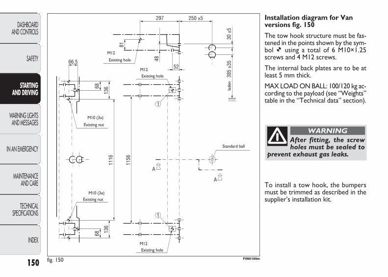
150
DASHBOARD AND CONTROLS
SAFETY
STARTING AND DRIVING
WARNING LIGHTSAND MESSAGES
IN AN EMERGENCY
MAINTENANCE AND CARE
TECHNICAL SPECIFICATIONS
INDEX
Installation diagram for Vanversions fig. 150
The tow hook structure must be fas-tened in the points shown by the sym-bol Ø using a total of 6 M10×1.25screws and 4 M12 screws.
The internal back plates are to be atleast 5 mm thick.
MAX LOAD ON BALL: 100/120 kg ac-cording to the payload (see “Weights”table in the “Technical data” section).
After fitting, the screwholes must be sealed to
prevent exhaust gas leaks.
WARNING
fig. 150 F0N0189m
Existing hole
Existing nut
Existing nut
Existing hole
Existing hole
lade
n
Standard ball
M12
M12
M10 (3x)
M10 (3x)
M12
To install a tow hook, the bumpersmust be trimmed as described in thesupplier’s installation kit.
141-154 DUCATO LUM EN 12-02-2010 8:52 Pagina 150
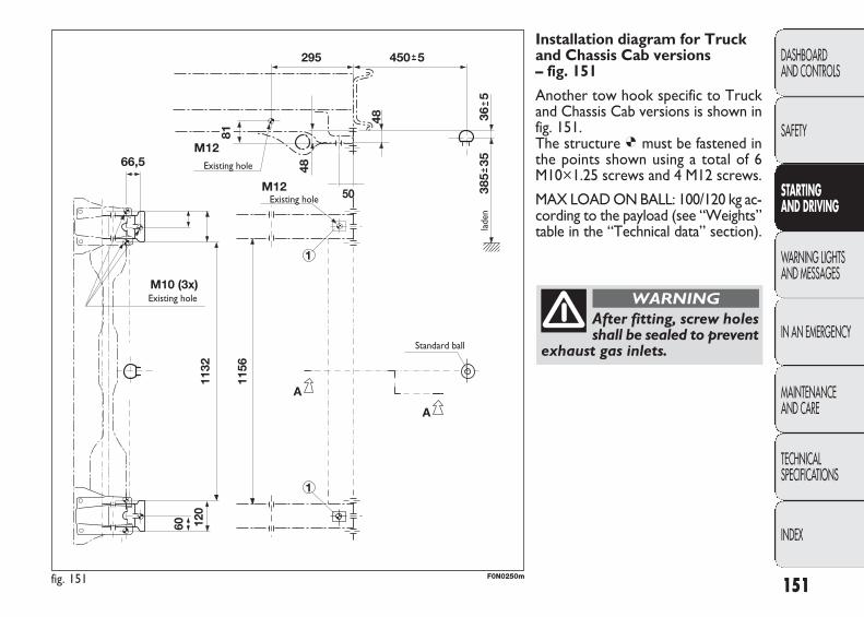
151
DASHBOARD AND CONTROLS
SAFETY
STARTING AND DRIVING
WARNING LIGHTSAND MESSAGES
IN AN EMERGENCY
MAINTENANCE AND CARE
TECHNICAL SPECIFICATIONS
INDEX
Installation diagram for Truckand Chassis Cab versions – fig. 151
Another tow hook specific to Truckand Chassis Cab versions is shown infig. 151. The structure Ø must be fastened inthe points shown using a total of 6M10×1.25 screws and 4 M12 screws.
MAX LOAD ON BALL: 100/120 kg ac-cording to the payload (see “Weights”table in the “Technical data” section).
After fitting, screw holesshall be sealed to prevent
exhaust gas inlets.
WARNING
fig. 151 F0N0250m
Existing hole
Existing hole
Existing hole
Standard ball
lade
n
141-154 DUCATO LUM EN 12-02-2010 8:52 Pagina 151
SNOW CHAINS
The use of snow chains should be in compliance withlocal regulations. The snow chains may be applied onlyonto the front wheel tyres (drive wheels). Use of Lin-eaccessori Fiat snow chains is recommended. Check thetension of the snow chains after the first few metres havebeen driven.
IMPORTANT With snow chains, use the accelerator withextreme care to prevent or to limit as much as possibleslipping of the driving wheels that could cause chain break-ing resulting in damages to the car body or mechanicalcomponents.
IMPORTANT Use low-dimensions snow chains.
SNOW TYRES
Fiat Dealership will be happy to provide advice concern-ing the most suitable type of tyres for the customer’s re-quirements. The performance of these tyres is consid-erably reduced when the tread depth is less than 4 mm.Replace them in this case. Due to their specific features,the performance of snow tyres is much lower than thatof normal types in normal conditions or long motorwaystretches. Limit performance according to the use forwhich they were approved.
IMPORTANT When snow tyres are used with a maxspeed index below the one that can be reached by thevehicle (increased by 5%), place a notice in the passengercompartment, plainly in view, which states the max per-missible speed of the snow tyres (as per EC Directive).
All four tyres should be the same (brand and track) to en-sure greater safety when driving and braking and better dri-veability. Remember that it is inappropriate to change therotation direction of tyres.
152
DASHBOARD AND CONTROLS
SAFETY
STARTING AND DRIVING
WARNING LIGHTSAND MESSAGES
IN AN EMERGENCY
MAINTENANCE AND CARE
TECHNICAL SPECIFICATIONS
INDEX
The max speed for snow tyres with “Q”marking is 160 km/h; 190 km/h for tyres
with “T” marking and 210 km/h for tyres with “H”marking. The Road Traffic Code speed limits must however be always strictly observed.
WARNING
Keep your speed down when snow chainsare fitted. Do not exceed 50 km/h. Avoidpotholes, steps and pavements and alsoavoid driving long distances on roads notcovered with snow in order to prevent
damaging the vehicle and the roadbed.
WARNING
141-154 DUCATO LUM EN 12-02-2010 8:52 Pagina 152
❒ cover the vehicle with a piece of fabric or perforatedplastic sheet. Do not use compact plastic tarpaulins,which prevent humidity from evaporating from the sur-face of the vehicle;
❒ inflate tyres to a pressure of +0.5 bar above the nor-mal specified pressure and check it at intervals;
❒ if you don’t disconnect the battery from the electric sys-tem, check its charge every month and recharge it if theoptical indicator shows a dark colour without the cen-tral green area;
❒ do not drain the engine cooling system.
IMPORTANT If the vehicle is equipped with an alarm,switch off the vehicle alarm with the remote control.
LONG VEHICLE INACTIVITY
If the vehicle needs to be off the road for longer than onemonth, the following precautions must be taken:
❒ park the vehicle indoors in a dry and, possibly, well-ven-tilated place;
❒ engage a gear;
❒ check that the handbrake is not engaged;
❒ disconnect the negative battery terminal and check bat-tery charge. Repeat this check once every three monthsduring storage. Recharge if the optical indicator showsa dark colour without the central green area (see “Bat-tery recharging” in the section “Dashboard and con-trols”); If the vehicle is equipped with a battery discon-nection function (disconnector), see the description ofthe procedure in the “Controls” paragraph in the“Dashboard and controls” section;
❒ clean and protect the painted parts using protectivewax;
❒ clean and protect the shiny metal parts using specialcompounds readily available;
❒ sprinkle talcum powder on the rubber windscreen andrear window wiper blades and lift them off the glass;
❒ slightly open the windows;
153
DASHBOARD AND CONTROLS
SAFETY
STARTING AND DRIVING
WARNING LIGHTSAND MESSAGES
IN AN EMERGENCY
MAINTENANCE AND CARE
TECHNICAL SPECIFICATIONS
INDEX
141-154 DUCATO LUM EN 12-02-2010 8:52 Pagina 153

page intentionally left blank
141-154 DUCATO LUM EN 12-02-2010 8:52 Pagina 154

WARNING LIGHTS AND MESSAGES
GENERAL WARNINGS
Lighting of a warning light is associated to a specific mes-sage and/or buzzer when applicable. These indications arebrief and precautionary and as such must not be consid-ered as exhaustive and/or alternative to the informationcontained in the Owner Handbook, which you are rec-ommended to read carefully in all cases. Always refer tothe information in this chapter in the event of a failure indication.
IMPORTANT Failure indications displayed are divided in-to two categories: very serious and less serious failures.
Serious faults have a repeated signals cycle for a long time.
Less serious faults have a signal cycle for a shorter time.
Press MODE to stop the warning cycle in both cases. The warning light on the instrument panel will stay on until the cause of the fault is eliminated.
For messages relevant to the versions equipped with Du-alogic gearbox, see the attached Supplement.
155
DASHBOARD AND CONTROLS
SAFETY
STARTING AND DRIVING
WARNING LIGHTSAND MESSAGES
IN AN EMERGENCY
MAINTENANCE AND CARE
TECHNICAL SPECIFICATIONS
INDEX
WARNING LIGHTS AND MESSAGES
If the warning light x turns on when trav-elling (on certain versions together with
the message on the display) stop the car imme-diately and contact Fiat Dealership.
WARNING
LOW BRAKE FLUID LEVEL (red)HANDBRAKE ON (red)
When the key is turned to the MAR position the warn-ing light comes on but should go out after a few seconds.
Low brake fluid level
The warning light comes on when the level of the brakefluid in the reservoir falls below the minimum level due toa possible leak in the circuit.
On some versions the display shows the dedicated message.
x
Handbrake on
The warning light turns on when the handbrake is on.
On certain versions, if the vehicle is moving the buzzer willalso sound.
IMPORTANT If the warning light turns on when travel-ling, check that the handbrake is not engaged.
155-164 DUCATO LUM EN 12-02-2010 8:53 Pagina 155

156
DASHBOARD AND CONTROLS
SAFETY
STARTING AND DRIVING
WARNING LIGHTSAND MESSAGES
IN AN EMERGENCY
MAINTENANCE AND CARE
TECHNICAL SPECIFICATIONS
INDEX
AIRBAG FAILURE (red)
When the key is turned to the MAR position the warninglight comes on but should go out after a few seconds.
The warning light stays on constantly if there is a failurein the air bag system.
On some versions the display shows the dedicated message.
¬
If when turning the key to MAR the warn-ing light ¬ does not turn on or if it stays
on when travelling (together with the message onthe multifunction display, where provided) therecould be a failure in safety systems; in this eventair bags or pretensioners may not be deployed incase of impact or, in a minor number of cases, theybe deployed accidentally. Contact a Fiat Dealer-ship immediately to have the system checked.
WARNING
HOT ENGINE COOLANT (red)
When the key is turned to the MAR position the warn-ing light comes on but should go out after a few seconds.
The warning light turns on when the engine is overheated.
ç
If the warning light comes on, proceed as follows:
❒ normal driving conditions: stop the car, switch off theengine and check whether the water level in the reser-voir is not below the MIN mark. In this case, wait for a few minutes for the engine to cool down, then slow-ly and carefully open the cap, top-up with coolant andcheck that the level is between the MIN and MAX ref-erences on the vessel itself Also check for fluid leaks.Contact a Fiat Dealershipa Fiat Dealership if the warn-ing should come on when the engine is started again;
❒ vehicle heavy duty (e.g.: towing trailer uphill of fully ladencar): decrease speed and if the warning light stays on,stop the vehicle. Stand for 2 or 3 minutes with the en-gine running and slightly accelerated to promote a bet-ter circulation of coolant. Then stop the engine. Checkcorrect liquid level as described above.
IMPORTANT Over demanding routes, it is advisable tokeep the engine on and slightly accelerated for a few min-utes before switching it off.
On some versions the display shows the dedicated message.
155-164 DUCATO LUM EN 12-02-2010 8:53 Pagina 156
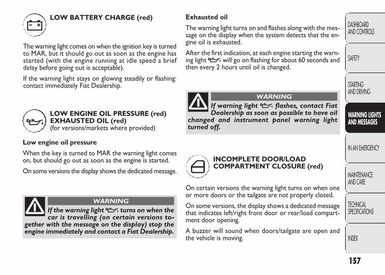
Exhausted oil
The warning light turns on and flashes along with the mes-sage on the display when the system detects that the en-gine oil is exhausted.
After the first indication, at each engine starting the warn-ing light v will go on flashing for about 60 seconds andthen every 2 hours until oil is changed.
157
DASHBOARD AND CONTROLS
SAFETY
STARTING AND DRIVING
WARNING LIGHTSAND MESSAGES
IN AN EMERGENCY
MAINTENANCE AND CARE
TECHNICAL SPECIFICATIONS
INDEX
LOW BATTERY CHARGE (red)
The warning light comes on when the ignition key is turnedto MAR, but it should go out as soon as the engine hasstarted (with the engine running at idle speed a brief delay before going out is acceptable).
If the warning light stays on glowing steadily or flashing:contact immediately Fiat Dealership.
w
LOW ENGINE OIL PRESSURE (red)EXHAUSTED OIL (red) (for versions/markets where provided)
Low engine oil pressure
When the key is turned to MAR the warning light comeson, but should go out as soon as the engine is started.
On some versions the display shows the dedicated message.
v
If the warning light v turns on when thecar is travelling (on certain versions to-
gether with the message on the display) stop theengine immediately and contact a Fiat Dealership.
WARNING
If warning light v flashes, contact FiatDealership as soon as possible to have oil
changed and instrument panel warning lightturned off.
WARNING
INCOMPLETE DOOR/LOAD COMPARTMENT CLOSURE (red)
On certain versions the warning light turns on when oneor more doors or the tailgate are not properly closed.
On some versions, the display shows a dedicated messagethat indicates left/right front door or rear/load compart-ment door opening.
A buzzer will sound when doors/tailgate are open andthe vehicle is moving.
´
155-164 DUCATO LUM EN 12-02-2010 8:53 Pagina 157

158
DASHBOARD AND CONTROLS
SAFETY
STARTING AND DRIVING
WARNING LIGHTSAND MESSAGES
IN AN EMERGENCY
MAINTENANCE AND CARE
TECHNICAL SPECIFICATIONS
INDEX
FRONT PASSENGER’S AIR BAG DEACTIVATED (amber) (for versions/markets, where provided)
Warning light F comes on when front passenger’s airbag is deactivated.
With front passenger air bag on, when the ignition key isturned to MAR the F warning light comes on constant-ly for about 4 seconds, flashes for another 4 seconds andthen should go out.
INEFFICIENT EBD ELECTRONIC BRAKING DISTRIBUTOR (red) (amber)
Warning lights x and > lit at the same time with theengine running, indicates an EBD system failure or that thesystem is not available. Early locking of the rear wheelsmay occur in the event of violent braking causing the carto swerve. Drive very carefully to a Fiat Dealership to havethe system inspected.
On some versions the display shows the dedicated message.
>
SEAT BELT NOT FASTENED (red)
The warning light on the display will light up when thevehicle is moving and the driver’s seat belt is not correctlyfastened. The warning light will blink and a buzzer willsound if the front seat belts are not correctly fastened.The buzzer of the S.B.R. (Seat Belt Reminder) system mayonly be switched off by a Fiat Dealership. On some ver-sions the system may be reactivated from the setup menu.
<
x
INJECTION SYSTEM FAILURE (amber)
In normal conditions, when the ignition key is moved toMAR, the warning light turns on and should go off afterengine start-up.
If the warning light stays on or turns on when travelling,means a fault in the supply/ignition system which couldcause high emissions at the exhaust, possible lack of per-formance, poor handling and high consumption levels.
On some versions the display shows the dedicated message.
In these conditions, you may continue travelling at mod-erate speed without demanding excessive effort from theengine. Contact a Fiat Dealershipa Fiat Dealership as soonas possible.
U
F
155-164 DUCATO LUM EN 12-02-2010 8:53 Pagina 158

159
DASHBOARD AND CONTROLS
SAFETY
STARTING AND DRIVING
WARNING LIGHTSAND MESSAGES
IN AN EMERGENCY
MAINTENANCE AND CARE
TECHNICAL SPECIFICATIONS
INDEX
FUEL RESERVE (amber)
This warning light comes on when the ignition key is turnedto MAR, but it should go off after a few seconds. The warning light turns on when about 10 to 12 litres offuel are left in the tank (depending on the version).IMPORTANT The warning light will blink to indicate a sys-tem failure. If this is the case, contact a Fiat Dealership tohave the system checked.
Warning light F indicates failure of warn-ing light ¬. This condition is indicated by
intermittent blinking of warning light “ for longerthan 4 seconds. In this case, warning light ¬maynot indicate fault to the system. Contact a FiatDealership immediately to have the systemchecked.
WARNING
ç
ABS SYSTEM FAILURE (amber)
When the key is turned to the MAR position the warninglight comes on but should go out after a few seconds.
The warning light will light up when the system is eithernot working or not available. Under these circumstancesthe braking system will work as normal without the extraperformance offered by the ABS system. Drive carefullyand contact a Fiat Dealership as soon as possible.
On some versions the display shows the dedicated message.
>GLOW PLUG WARMING (Multijet versions – amber)
GLOW PLUG HEATING FAILURE(Multijet versions – amber)
Glow plugs
This warning light comes on when the key is turned toMAR. It will go out as soon as the heater plugs havereached a preset temperature. Start the engine as soon asthe warning light goes out.IMPORTANT At high ambient temperatures the warn-ing light stays on for an extremely short time.
Glow plug warming failure
The warning light flashes if there is a fault in the preheat-ing system. Contact a Fiat Dealershipa Fiat Dealership assoon as possible. On some versions the display shows the dedicated message.
m
155-164 DUCATO LUM EN 12-02-2010 8:53 Pagina 159
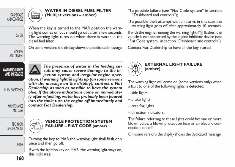
160
DASHBOARD AND CONTROLS
SAFETY
STARTING AND DRIVING
WARNING LIGHTSAND MESSAGES
IN AN EMERGENCY
MAINTENANCE AND CARE
TECHNICAL SPECIFICATIONS
INDEX
The presence of water in the feeding cir-cuit may cause severe damage to the in-jection system and irregular engine oper-
ation. If warning light c lights up (on some versionswith the message on the display), contact a FiatDealership as soon as possible to have the systembled. If the above indications come on immediate-ly after refuelling, water has probably been pouredinto the tank: turn the engine off immediately andcontact Fiat Dealership.
WATER IN DIESEL FUEL FILTER (Multijet versions – amber)
When the key is turned to the MAR position the warn-ing light comes on but should go out after a few seconds. The warning light turns on when there is water in thediesel fuel filter.
On some versions the display shows the dedicated message.
c
VEHICLE PROTECTION SYSTEMFAILURE – FIAT CODE (amber)
Turning the key to MAR the warning light shall flash onlyonce and then go off.
If with the ignition key on MAR, the warning light stays on,this indicates:
Y
EXTERNAL LIGHT FAILURE(amber)
The warning light will come on (some versions only) whena fault to one of the following lights is detected:
– side lights
– brake lights
– rear fog lights
– direction indicators.
The failure referring to these lights could be: one or moreblown bulbs, a blown protection fuse or an electric con-nection cut-off.
On some versions the display shows the dedicated message.
W
❒ a possible failure (see “Fiat Code system” in section“Dashboard and controls”);
❒ a possible theft attempt with an alarm; in this case thewarning light goes off after approximately 10 seconds.
If with the engine running the warning light Y flashes, thevehicle is not protected by the engine inhibitor device (see“Fiat Code system” in section “Dashboard and controls”).
Contact Fiat Dealership to have all the key stored.
155-164 DUCATO LUM EN 12-02-2010 8:53 Pagina 160
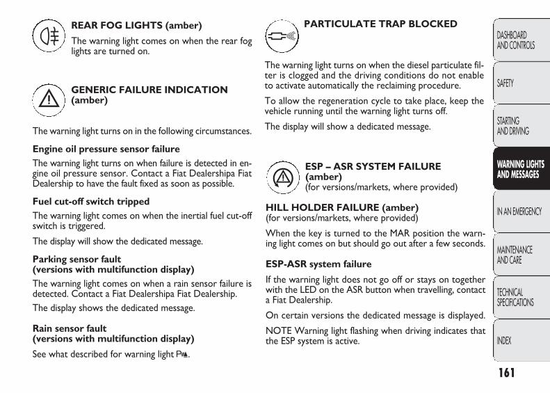
161
DASHBOARD AND CONTROLS
SAFETY
STARTING AND DRIVING
WARNING LIGHTSAND MESSAGES
IN AN EMERGENCY
MAINTENANCE AND CARE
TECHNICAL SPECIFICATIONS
INDEX
REAR FOG LIGHTS (amber)
The warning light comes on when the rear foglights are turned on.
4
GENERIC FAILURE INDICATION (amber)
The warning light turns on in the following circumstances.
Engine oil pressure sensor failureThe warning light turns on when failure is detected in en-gine oil pressure sensor. Contact a Fiat Dealershipa FiatDealership to have the fault fixed as soon as possible.
Fuel cut-off switch trippedThe warning light comes on when the inertial fuel cut-offswitch is triggered.
The display will show the dedicated message.
Parking sensor fault(versions with multifunction display)The warning light comes on when a rain sensor failure isdetected. Contact a Fiat Dealershipa Fiat Dealership.The display shows the dedicated message.
Rain sensor fault(versions with multifunction display)
See what described for warning light t.
è
PARTICULATE TRAP BLOCKED
The warning light turns on when the diesel particulate fil-ter is clogged and the driving conditions do not enableto activate automatically the reclaiming procedure.
To allow the regeneration cycle to take place, keep thevehicle running until the warning light turns off.
The display will show a dedicated message.
ESP – ASR SYSTEM FAILURE (amber) (for versions/markets, where provided)
HILL HOLDER FAILURE (amber) (for versions/markets, where provided)
When the key is turned to the MAR position the warn-ing light comes on but should go out after a few seconds.
ESP-ASR system failure
If the warning light does not go off or stays on togetherwith the LED on the ASR button when travelling, contacta Fiat Dealership.
On certain versions the dedicated message is displayed.
NOTE Warning light flashing when driving indicates thatthe ESP system is active.
á
h
155-164 DUCATO LUM EN 12-02-2010 8:53 Pagina 161
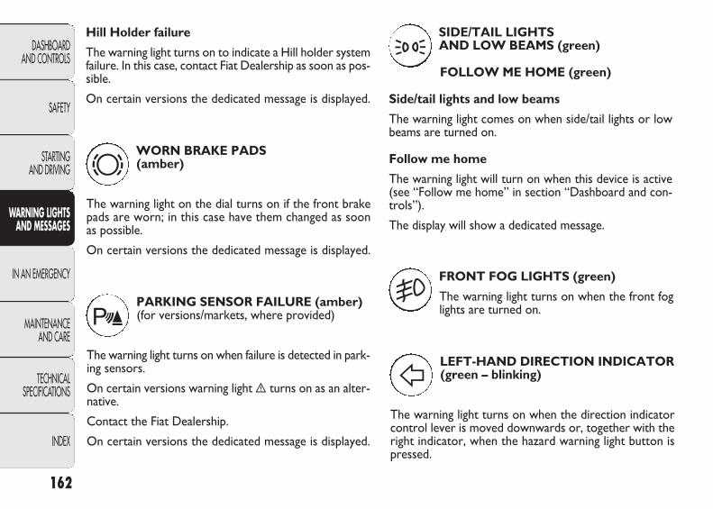
162
DASHBOARD AND CONTROLS
SAFETY
STARTING AND DRIVING
WARNING LIGHTSAND MESSAGES
IN AN EMERGENCY
MAINTENANCE AND CARE
TECHNICAL SPECIFICATIONS
INDEX
WORN BRAKE PADS (amber)
The warning light on the dial turns on if the front brakepads are worn; in this case have them changed as soonas possible.
On certain versions the dedicated message is displayed.
d
Hill Holder failure
The warning light turns on to indicate a Hill holder systemfailure. In this case, contact Fiat Dealership as soon as pos-sible.
On certain versions the dedicated message is displayed.
PARKING SENSOR FAILURE (amber) (for versions/markets, where provided)
The warning light turns on when failure is detected in park-ing sensors.
On certain versions warning light è turns on as an alter-native.
Contact the Fiat Dealership.
On certain versions the dedicated message is displayed.
t
FRONT FOG LIGHTS (green)
The warning light turns on when the front foglights are turned on.
5
LEFT-HAND DIRECTION INDICATOR(green – blinking)
The warning light turns on when the direction indicatorcontrol lever is moved downwards or, together with theright indicator, when the hazard warning light button ispressed.
F
SIDE/TAIL LIGHTS AND LOW BEAMS (green)
FOLLOW ME HOME (green)
Side/tail lights and low beams
The warning light comes on when side/tail lights or lowbeams are turned on.
Follow me home
The warning light will turn on when this device is active(see “Follow me home” in section “Dashboard and con-trols”).
The display will show a dedicated message.
3
155-164 DUCATO LUM EN 12-02-2010 8:53 Pagina 162
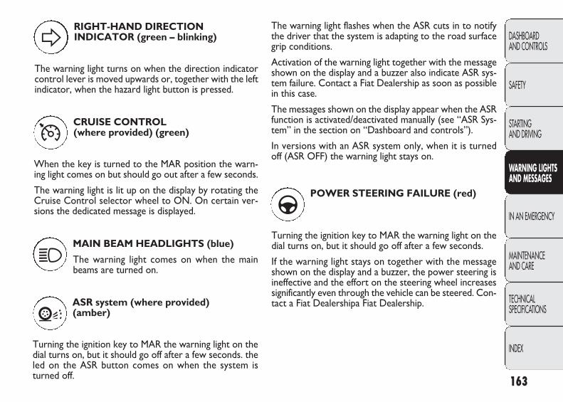
163
DASHBOARD AND CONTROLS
SAFETY
STARTING AND DRIVING
WARNING LIGHTSAND MESSAGES
IN AN EMERGENCY
MAINTENANCE AND CARE
TECHNICAL SPECIFICATIONS
INDEX
CRUISE CONTROL(where provided) (green)
When the key is turned to the MAR position the warn-ing light comes on but should go out after a few seconds.
The warning light is lit up on the display by rotating theCruise Control selector wheel to ON. On certain ver-sions the dedicated message is displayed.
Ü
RIGHT-HAND DIRECTION INDICATOR (green – blinking)
The warning light turns on when the direction indicatorcontrol lever is moved upwards or, together with the leftindicator, when the hazard light button is pressed.
D
MAIN BEAM HEADLIGHTS (blue)
The warning light comes on when the mainbeams are turned on.
1
ASR system (where provided)(amber)
Turning the ignition key to MAR the warning light on thedial turns on, but it should go off after a few seconds. theled on the ASR button comes on when the system isturned off.
V
The warning light flashes when the ASR cuts in to notifythe driver that the system is adapting to the road surfacegrip conditions.
Activation of the warning light together with the messageshown on the display and a buzzer also indicate ASR sys-tem failure. Contact a Fiat Dealership as soon as possiblein this case.
The messages shown on the display appear when the ASRfunction is activated/deactivated manually (see “ASR Sys-tem” in the section on “Dashboard and controls”).
In versions with an ASR system only, when it is turnedoff (ASR OFF) the warning light stays on.
POWER STEERING FAILURE (red)
Turning the ignition key to MAR the warning light on thedial turns on, but it should go off after a few seconds.
If the warning light stays on together with the messageshown on the display and a buzzer, the power steering isineffective and the effort on the steering wheel increasessignificantly even through the vehicle can be steered. Con-tact a Fiat Dealershipa Fiat Dealership.
g
155-164 DUCATO LUM EN 12-02-2010 8:53 Pagina 163

164
DASHBOARD AND CONTROLS
SAFETY
STARTING AND DRIVING
WARNING LIGHTSAND MESSAGES
IN AN EMERGENCY
MAINTENANCE AND CARE
TECHNICAL SPECIFICATIONS
INDEX
The warning light on the dial comes on steady (along withthe display of the message and a buzzer) to indicate thatthe automatic transmission oil temperature is too high.
POSSIBLE ICE ON ROAD
This indication starts flashing when the outside tempera-ture reaches or falls below 3°C to warn the driver of thepossible presence of ice on the road.
The display will show the dedicated message (only for ver-sions with a multifunction display).
LIMITED RANGE(versions with multifunction display)
The display will show the dedicated message to warn thedriver that the cruising range is less than 50 km.
SPEED LIMIT EXCEEDED
The display shows the dedicated message when the vehi-cle exceeds the set speed limit (see “Multifunction Dis-play” in section “Dashboard and controls”).
SCHEDULED MAINTENANCE (for versions/markets where provided)
This warning light comes on at the scheduled service warn-ings and stays on with a fixed light when the deadline isreached. The warning light goes off after the service hasbeen carried out at a Fiat Dealership or once 1000 kmhave been covered at the service deadline.
õ
AUTOMATIC TRANSMISSION FAILURE/MAXIMUM TRANSMISSIONOIL TEMPERATURE (red)(for versions/markets where provided)
Turning the ignition key to MAR the warning light on thedial turns on, but it should go off after a few seconds.
The warning light on the dial comes on blinking (along withthe display of the message and a buzzer) when a trans-mission failure is detected.
SELF-LEVELLING SUSPENSION FAILURE (red) (for versions/markets where provided)
This warning light comes on when the ignition key isturned to MAR, but it should go off after a few seconds.
The warning light goes on when a fault is present in theself-levelling suspension system.
Œ
t
155-164 DUCATO LUM EN 12-02-2010 8:53 Pagina 164
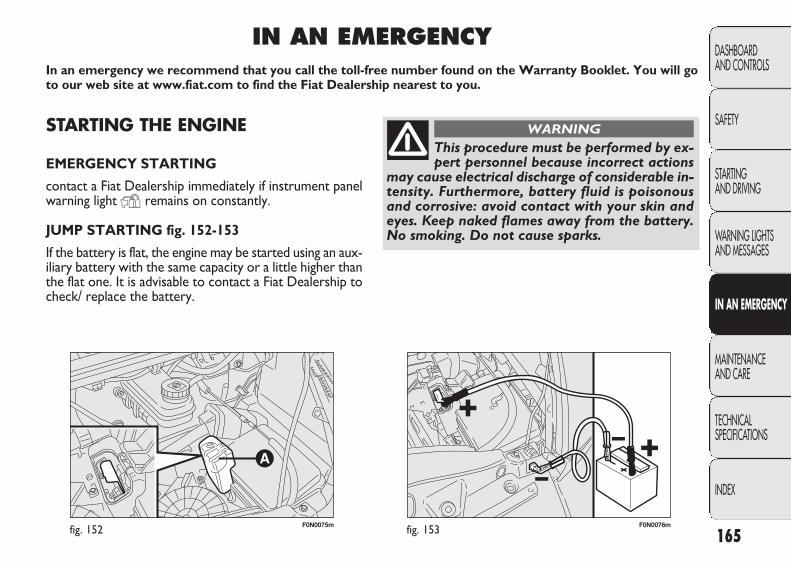
F0N0075mfig. 152 F0N0076mfig. 153 165
DASHBOARD AND CONTROLS
SAFETY
STARTING AND DRIVING
WARNING LIGHTSAND MESSAGES
IN AN EMERGENCY
MAINTENANCE AND CARE
TECHNICAL SPECIFICATIONS
INDEX
STARTING THE ENGINE
EMERGENCY STARTING
contact a Fiat Dealership immediately if instrument panelwarning light Y remains on constantly.
JUMP STARTING fig. 152-153
If the battery is flat, the engine may be started using an aux-iliary battery with the same capacity or a little higher thanthe flat one. It is advisable to contact a Fiat Dealership tocheck/ replace the battery.
IN AN EMERGENCYIn an emergency we recommend that you call the toll-free number found on the Warranty Booklet. You will goto our web site at www.fiat.com to find the Fiat Dealership nearest to you.
This procedure must be performed by ex-pert personnel because incorrect actions
may cause electrical discharge of considerable in-tensity. Furthermore, battery fluid is poisonousand corrosive: avoid contact with your skin andeyes. Keep naked flames away from the battery.No smoking. Do not cause sparks.
WARNING
165-198 DUCATO LUM EN 12-02-2010 8:43 Pagina 165

REPLACING A WHEEL
GENERAL INSTRUCTIONS
Wheel changing and correct use of the jack and sparewheel (for versions/markets, where provided) call for someprecautions as listed below.
Proceed as follows to start the car:
❒ raise the flap A to gain access to the battery positiveterminal fig. 152.
❒ connect the positive terminals (+ sign near terminal) ofboth batteries using a lead;
❒ connect a second cable to the negative terminal (–) ofthe auxiliary battery to the earth point as shown infig. 153;
❒ start the engine;
❒ when the engine has been started, follow the sequenceabove in reverse order to remove the leads.
If after a few attempts the engine does not start, do notinsist but contact the nearest Fiat Dealership.
IMPORTANT Do not directly connect the negative terminalsof the two batteries: sparks could ignite the flammable gas fromthe battery. If the auxiliary battery is installed on another ve-hicle, avoid any metal parts on the latter and the vehicle withthe flat battery from accidentally coming into contact.
BUMP STARTING
Never bump start the engine by pushing, towing or drivingdownhill. This could cause a flow of fuel into the catalyticconverter and damage it beyond repair.
IMPORTANT Remember that the brake servo and thepower steering system are not activated until the engineis started, a greater effort will therefore be required topress the brake pedal or turn the steering wheel.
166
DASHBOARD AND CONTROLS
SAFETY
STARTING AND DRIVING
WARNING LIGHTSAND MESSAGES
IN AN EMERGENCY
MAINTENANCE AND CARE
TECHNICAL SPECIFICATIONS
INDEX
Indicate that the vehicle is stationary ac-cording to the regulations in force: emer-
gency lights, refracting warning triangle, etc. Pas-sengers should leave the vehicle, particularly if itis very loaded, and wait for the wheel to bechanged away from on-coming traffic. Apply thehandbrake.
WARNING
The spare wheel (for versions/markets,where provided) (where provided) is spe-
cific for your vehicle. Therefore, it must not beused on vehicles of a different model. Do not usespare wheels of different models on your vehicle.Wheel bolts are specific to your vehicle: do notuse them on other models and do not use boltsof other models.
WARNING
165-198 DUCATO LUM EN 12-02-2010 8:43 Pagina 166
Important notes:
❒ the jack weight is 4.5 kg;
❒ the jack requires no adjustment;
❒ the jack cannot be repaired. If it breaks it must be re-placed with a new jack;
❒ no tool other than its cranking device may be fitted onthe jack.
167
DASHBOARD AND CONTROLS
SAFETY
STARTING AND DRIVING
WARNING LIGHTSAND MESSAGES
IN AN EMERGENCY
MAINTENANCE AND CARE
TECHNICAL SPECIFICATIONS
INDEX
Repair and refit the standard wheel assoon as possible. Do not apply grease to
the bolt threading before assembly: they mightcome unscrewed.
WARNING
The jack may only be used to replacewheels on the car which it equips or oth-
er cars of the same model. Never use the jack forother purposes, such as lifting other car models.Never use the jack to carry out repairs under thevehicle. Incorrect positioning of the jack maycause the lifted vehicle to fall. Do not use the jackfor loads higher than those shown on the label.
WARNING
Never tamper with the inflation valve.Never introduce tools of any kind between
rim and tyre. Check tyre and spare wheel pressureregularly referring to the values shown in the“Technical Specifications” section.
WARNING
No tools other than the crank providedshould be used with the spare wheel lift-
ing device; it should be operated by hand, only.
WARNING
To change a wheel proceed as follows:❒ stop the vehicle in a position so that it is not a danger
for on-coming traffic in a location where you can re-place the wheel safely. The ground must be flat andcompact;
❒ turn the engine off and pull up the handbrake;❒ engage first gear or reverse;❒ wear the reflecting safety jacket (compulsory by law in
certain countries) before getting out of the vehicle;
165-198 DUCATO LUM EN 12-02-2010 8:43 Pagina 167
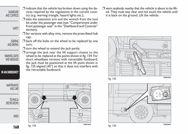
F0N0193mfig. 154 F0N0390mfig. 156
F0N0194mfig. 155
❒ warn anybody nearby that the vehicle is about to be lift-ed. They must stay clear and not touch the vehicle untilit is back on the ground. Lift the vehicle.
❒ indicate that the vehicle has broken down using the de-vices required by the regulations in the current coun-try (e.g. warning triangle, hazard lights etc.);
❒ take the extension arm and the wrench from the toolkit under the passenger seat (see “Compartment underfront passenger seat” in the “Dashboard and Controls”section);
❒ for versions with alloy rims, remove the press-fitted hubcap;
❒ back off the bolts on the wheel to be replaced by oneturn;
❒ turn the wheel to extend the jack partly;❒ arrange the jack near the lift support closest to the
wheel to be replaced at the points shown in fig. 154. Forshort wheelbase versions with retractable footboard,the jack must be positioned at the lift point shown infig. 155 aligned (45°) so that it does not interfere withthe retractable footboard;
168
DASHBOARD AND CONTROLS
SAFETY
STARTING AND DRIVING
WARNING LIGHTSAND MESSAGES
IN AN EMERGENCY
MAINTENANCE AND CARE
TECHNICAL SPECIFICATIONS
INDEX
165-198 DUCATO LUM EN 12-02-2010 8:43 Pagina 168
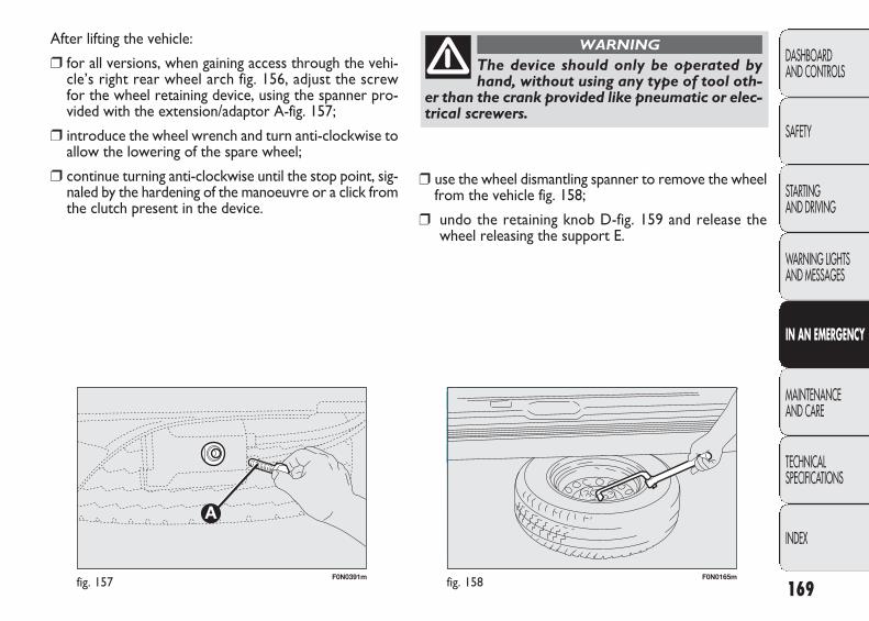
A
F0N0391mfig. 157 F0N0165mfig. 158
❒ use the wheel dismantling spanner to remove the wheelfrom the vehicle fig. 158;
❒ undo the retaining knob D-fig. 159 and release thewheel releasing the support E.
After lifting the vehicle:
❒ for all versions, when gaining access through the vehi-cle’s right rear wheel arch fig. 156, adjust the screwfor the wheel retaining device, using the spanner pro-vided with the extension/adaptor A-fig. 157;
❒ introduce the wheel wrench and turn anti-clockwise toallow the lowering of the spare wheel;
❒ continue turning anti-clockwise until the stop point, sig-naled by the hardening of the manoeuvre or a click fromthe clutch present in the device.
169
DASHBOARD AND CONTROLS
SAFETY
STARTING AND DRIVING
WARNING LIGHTSAND MESSAGES
IN AN EMERGENCY
MAINTENANCE AND CARE
TECHNICAL SPECIFICATIONS
INDEX
The device should only be operated byhand, without using any type of tool oth-
er than the crank provided like pneumatic or elec-trical screwers.
WARNING
165-198 DUCATO LUM EN 12-02-2010 8:43 Pagina 169
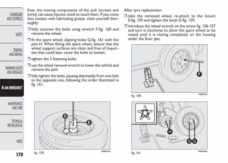
F0N0370mfig. 159 F0N0168mfig. 161
F0N0167mfig. 160
After tyre replacement:❒ take the removed wheel, re-attach to the mount
E-fig. 159 and tighten the knob D-fig. 159;❒ introduce the wheel wrench on the screw fig. 156-157
and turn it clockwise to allow the spare wheel to beraised until it is resting completely on the housing under the floor pan.
Even the moving components of the jack (screws andjoints) can cause injuries: avoid to touch them. If you comeinto contact with lubricating grease, clean yourself thor-oughly;
❒ fully unscrew the bolts using wrench F-fig. 160 and remove the wheel;
❒ fit the spare wheel, aligning holes G-fig. 161 with thepins H. When fitting the spare wheel, ensure that thewheel support surfaces are clean and free of impuri-ties that could later cause the bolts to loosen;
❒ tighten the 5 fastening bolts;
❒ use the wheel removal wrench to lower the vehicle andremove the jack;
❒ fully tighten the bolts, passing alternately from one boltto the opposite one, following the order illustrated infig. 161.
170
DASHBOARD AND CONTROLS
SAFETY
STARTING AND DRIVING
WARNING LIGHTSAND MESSAGES
IN AN EMERGENCY
MAINTENANCE AND CARE
TECHNICAL SPECIFICATIONS
INDEX
165-198 DUCATO LUM EN 12-02-2010 8:43 Pagina 170

F0N0251mfig. 163F0N0223mfig. 162
For vehicles with allow rims, proceed as follows:
– take the kit from the tool box;
– fit plate A-fig. 163 to the alloy wheel, securing withscrews B-fig. 163 provided with the wrench;
171
DASHBOARD AND CONTROLS
SAFETY
STARTING AND DRIVING
WARNING LIGHTSAND MESSAGES
IN AN EMERGENCY
MAINTENANCE AND CARE
TECHNICAL SPECIFICATIONS
INDEX
At the end of the operation of raising/locking the spare wheel, the key must be
extracted, taking care not to turn it in the wrongdirection when trying to facilitate the extractionof the actual key, to prevent the attachment de-vice from being released and the wheel assemblynot being securely retained fig. 162.
WARNING – refit the wheel to the mount and turn to the end of theslot (as shown in fig. 164) and tighten the knob D-fig. 164;
– introduce the wheel removal wrench on the screw fig.156 and turn it clockwise to allow the spare wheel to beraised.
❒ Check that it is correctly positioned in the dedicatedhousing under the floor pan (the lifting system has anend of travel clutch which, if incorrectly positioned, willbe unsafe);
❒ place the removal spanner back in the tool box;❒ place the tool box in its housing under the passenger seat.
165-198 DUCATO LUM EN 12-02-2010 8:43 Pagina 171

F0N0371mfig. 164
E
F0N0825mfig. 165
QUICK TYRE REPAIR KIT – Automatic FIX & GO(for versions/markets, where provided)
The automatic tyre Fix & Go repair kit is positioned at thefront of the vehicle passenger compartment and includes:
❒ bottle A containing sealer and fitted with:
– a transparent filler pipe B;
– a black pressure restore pipe E;
– an adhesive label C with the message “max. 80 km/h”to be apply in a position clearly visible by the driver(on the dashboard) after repairing the tyre;
❒ informative leaflet (see fig. 166), used to ensure the cor-rect use of the quick tyre repair kit and then given tothe personnel who will handle the treated tyre;
172
DASHBOARD AND CONTROLS
SAFETY
STARTING AND DRIVING
WARNING LIGHTSAND MESSAGES
IN AN EMERGENCY
MAINTENANCE AND CARE
TECHNICAL SPECIFICATIONS
INDEX
Each time the spare wheel is moved, checkthat it is correctly positioned in its hous-
ing under the floor. If it is not correctly positioned,this could adversely affect safety.
WARNING
165-198 DUCATO LUM EN 12-02-2010 8:43 Pagina 172
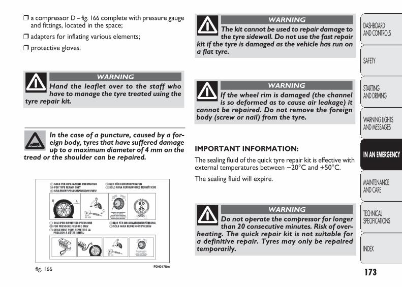
F0N0178mfig. 166
❒ a compressor D – fig. 166 complete with pressure gaugeand fittings, located in the space;
❒ adapters for inflating various elements;
❒ protective gloves.
173
DASHBOARD AND CONTROLS
SAFETY
STARTING AND DRIVING
WARNING LIGHTSAND MESSAGES
IN AN EMERGENCY
MAINTENANCE AND CARE
TECHNICAL SPECIFICATIONS
INDEX
Hand the leaflet over to the staff whohave to manage the tyre treated using the
tyre repair kit.
WARNING
In the case of a puncture, caused by a for-eign body, tyres that have suffered damageup to a maximum diameter of 4 mm on the
tread or the shoulder can be repaired.
The kit cannot be used to repair damage tothe tyre sidewall. Do not use the fast repair
kit if the tyre is damaged as the vehicle has run ona flat tyre.
WARNING
If the wheel rim is damaged (the channelis so deformed as to cause air leakage) it
cannot be repaired. Do not remove the foreignbody (screw or nail) from the tyre.
WARNING
IMPORTANT INFORMATION:
The sealing fluid of the quick tyre repair kit is effective withexternal temperatures between −20°C and +50°C.
The sealing fluid will expire.
Do not operate the compressor for longerthan 20 consecutive minutes. Risk of over-
heating. The quick repair kit is not suitable for a definitive repair. Tyres may only be repairedtemporarily.
WARNING
165-198 DUCATO LUM EN 12-02-2010 8:43 Pagina 173
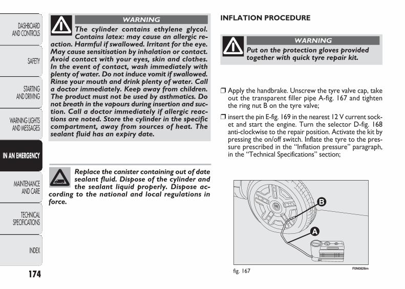
F0N0826mfig. 167
INFLATION PROCEDURE
174
DASHBOARD AND CONTROLS
SAFETY
STARTING AND DRIVING
WARNING LIGHTSAND MESSAGES
IN AN EMERGENCY
MAINTENANCE AND CARE
TECHNICAL SPECIFICATIONS
INDEX
The cylinder contains ethylene glycol.Contains latex: may cause an allergic re-
action. Harmful if swallowed. Irritant for the eye.May cause sensitisation by inhalation or contact.Avoid contact with your eyes, skin and clothes.In the event of contact, wash immediately withplenty of water. Do not induce vomit if swallowed.Rinse your mouth and drink plenty of water. Calla doctor immediately. Keep away from children.The product must not be used by asthmatics. Donot breath in the vapours during insertion and suc-tion. Call a doctor immediately if allergic reac-tions are noted. Store the cylinder in the specificcompartment, away from sources of heat. Thesealant fluid has an expiry date.
WARNING
Replace the canister containing out of datesealant fluid. Dispose of the cylinder andthe sealant liquid properly. Dispose ac-
cording to the national and local regulations inforce.
Put on the protection gloves providedtogether with quick tyre repair kit.
WARNING
❒ Apply the handbrake. Unscrew the tyre valve cap, takeout the transparent filler pipe A-fig. 167 and tighten the ring nut B on the tyre valve;
❒ insert the pin E-fig. 169 in the nearest 12 V current sock-et and start the engine. Turn the selector D-fig. 168 anti-clockwise to the repair position. Activate the kit bypressing the on/off switch. Inflate the tyre to the pres-sure prescribed in the “Inflation pressure” paragraph,in the “Technical Specifications” section;
165-198 DUCATO LUM EN 12-02-2010 8:43 Pagina 174
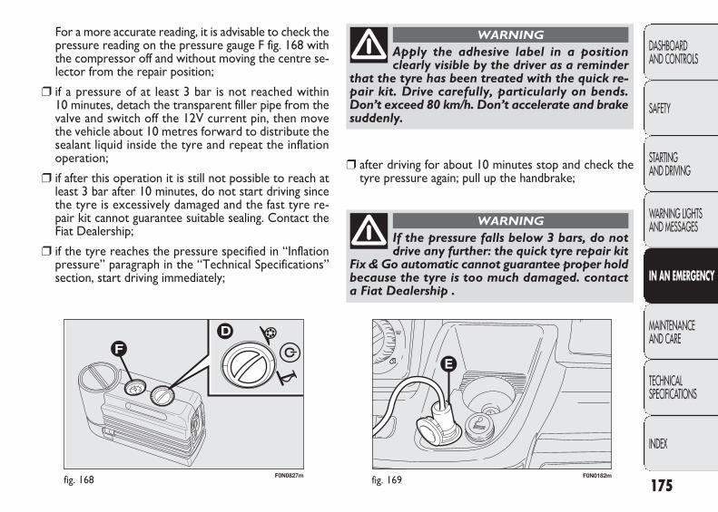
F0N0182mfig. 169F0N0827mfig. 168
For a more accurate reading, it is advisable to check thepressure reading on the pressure gauge F fig. 168 withthe compressor off and without moving the centre se-lector from the repair position;
❒ if a pressure of at least 3 bar is not reached within 10 minutes, detach the transparent filler pipe from thevalve and switch off the 12V current pin, then movethe vehicle about 10 metres forward to distribute thesealant liquid inside the tyre and repeat the inflationoperation;
❒ if after this operation it is still not possible to reach atleast 3 bar after 10 minutes, do not start driving sincethe tyre is excessively damaged and the fast tyre re-pair kit cannot guarantee suitable sealing. Contact theFiat Dealership;
❒ if the tyre reaches the pressure specified in “Inflationpressure” paragraph in the “Technical Specifications”section, start driving immediately;
175
DASHBOARD AND CONTROLS
SAFETY
STARTING AND DRIVING
WARNING LIGHTSAND MESSAGES
IN AN EMERGENCY
MAINTENANCE AND CARE
TECHNICAL SPECIFICATIONS
INDEX
Apply the adhesive label in a positionclearly visible by the driver as a reminder
that the tyre has been treated with the quick re-pair kit. Drive carefully, particularly on bends.Don’t exceed 80 km/h. Don’t accelerate and brakesuddenly.
WARNING
❒ after driving for about 10 minutes stop and check thetyre pressure again; pull up the handbrake;
If the pressure falls below 3 bars, do notdrive any further: the quick tyre repair kit
Fix & Go automatic cannot guarantee proper holdbecause the tyre is too much damaged. contacta Fiat Dealership .
WARNING
165-198 DUCATO LUM EN 12-02-2010 8:43 Pagina 175
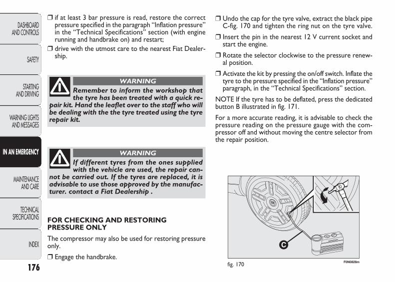
F0N0828mfig. 170
❒ if at least 3 bar pressure is read, restore the correctpressure specified in the paragraph “Inflation pressure”in the “Technical Specifications” section (with enginerunning and handbrake on) and restart;
❒ drive with the utmost care to the nearest Fiat Dealer-ship.
176
DASHBOARD AND CONTROLS
SAFETY
STARTING AND DRIVING
WARNING LIGHTSAND MESSAGES
IN AN EMERGENCY
MAINTENANCE AND CARE
TECHNICAL SPECIFICATIONS
INDEX
Remember to inform the workshop thatthe tyre has been treated with a quick re-
pair kit. Hand the leaflet over to the staff who willbe dealing with the the tyre treated using the tyrerepair kit.
WARNING
If different tyres from the ones suppliedwith the vehicle are used, the repair can-
not be carried out. If the tyres are replaced, it isadvisable to use those approved by the manufac-turer. contact a Fiat Dealership .
WARNING
❒ Undo the cap for the tyre valve, extract the black pipeC-fig. 170 and tighten the ring nut on the tyre valve.
❒ Insert the pin in the nearest 12 V current socket andstart the engine.
❒ Rotate the selector clockwise to the pressure renew-al position.
❒ Activate the kit by pressing the on/off switch. Inflate thetyre to the pressure specified in the “Inflation pressure”paragraph, in the “Technical Specifications” section.
NOTE If the tyre has to be deflated, press the dedicatedbutton B illustrated in fig. 171.
For a more accurate reading, it is advisable to check thepressure reading on the pressure gauge with the com-pressor off and without moving the centre selector fromthe repair position.
FOR CHECKING AND RESTORING PRESSURE ONLY
The compressor may also be used for restoring pressureonly.
❒ Engage the handbrake.
165-198 DUCATO LUM EN 12-02-2010 8:43 Pagina 176

B
F0N0830mfig. 171
F0N0829mfig. 172
WHEN NEEDING TO CHANGE A BULB
GENERAL INSTRUCTIONS
❒ When a light is not working, check that the corre-sponding fuse is intact before changing a bulb. For thelocation of fuses, refer to the paragraph “If a fuse blows”in this section;
❒ before changing a bulb check the contacts for oxidation;
❒ burnt bulbs must be replaced by others of the same typeand power;
❒ always check the height of the headlight beam afterchanging a bulb.
CYLINDER REPLACEMENT PROCEDURE
To replace the cylinder, proceed as follows:
❒ press button A – fig. 172 to release the replacementpart;
❒ fit the new cylinder and press until it is automatically engaged.
177
DASHBOARD AND CONTROLS
SAFETY
STARTING AND DRIVING
WARNING LIGHTSAND MESSAGES
IN AN EMERGENCY
MAINTENANCE AND CARE
TECHNICAL SPECIFICATIONS
INDEX
Halogen lamps must be handled holdingthe metallic part only. Touching the trans-parent part of the bulb with your fingers
may reduce the intensity of the emitted light andeven compromise duration of the bulb itself. In theevent of accidental contact, rub the bulb with a clothdampened with alcohol and let it dry.
165-198 DUCATO LUM EN 12-02-2010 8:43 Pagina 177
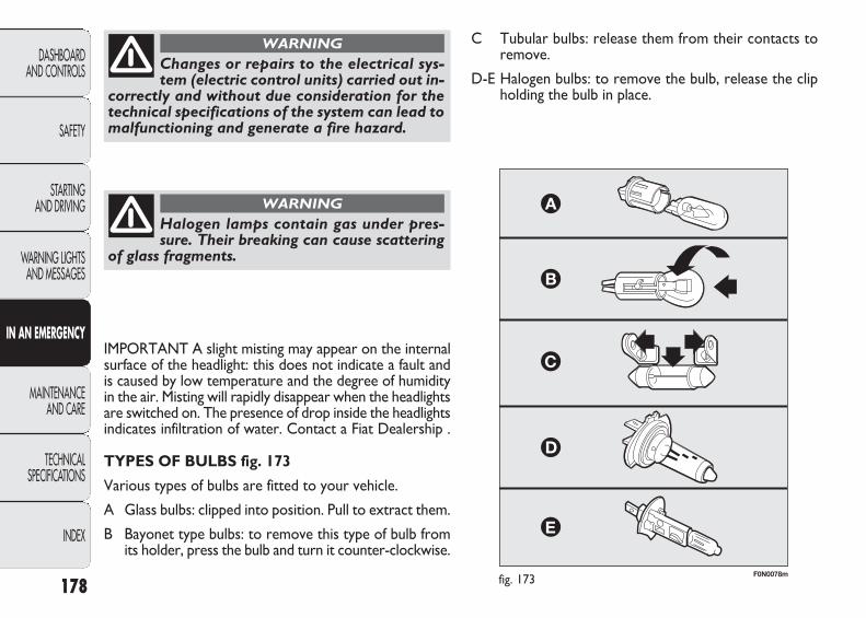
F0N0078mfig. 173
Changes or repairs to the electrical sys-tem (electric control units) carried out in-
correctly and without due consideration for thetechnical specifications of the system can lead tomalfunctioning and generate a fire hazard.
WARNING
Halogen lamps contain gas under pres-sure. Their breaking can cause scattering
of glass fragments.
WARNING
IMPORTANT A slight misting may appear on the internalsurface of the headlight: this does not indicate a fault andis caused by low temperature and the degree of humidityin the air. Misting will rapidly disappear when the headlightsare switched on. The presence of drop inside the headlightsindicates infiltration of water. Contact a Fiat Dealership .
TYPES OF BULBS fig. 173
Various types of bulbs are fitted to your vehicle.
A Glass bulbs: clipped into position. Pull to extract them.
B Bayonet type bulbs: to remove this type of bulb fromits holder, press the bulb and turn it counter-clockwise.
C Tubular bulbs: release them from their contacts toremove.
D-E Halogen bulbs: to remove the bulb, release the clipholding the bulb in place.
178
DASHBOARD AND CONTROLS
SAFETY
STARTING AND DRIVING
WARNING LIGHTSAND MESSAGES
IN AN EMERGENCY
MAINTENANCE AND CARE
TECHNICAL SPECIFICATIONS
INDEX
165-198 DUCATO LUM EN 12-02-2010 8:43 Pagina 178

D
D
A
–
B
A
B
A
B
B
B
–
–
–
A
C
C
H1
H7
W5W
H1
PY21W
W16WF(*)/WY5W(▼)
PY21W
W5W
P21/5W
P21/5W
P21W
P21W
P21W
P21W
C5W
12V10W
12V10W
55 W
55 W
5 W
55 W
21 W
16 W(*)/5 W(▼)
21 W
5 W
5 W
5 W
21W
21 W
21 W
21 W
5 W
10 W
10 W
Bulbs Rif. fig. 173 Type Power
Main beam headlamps
Dipped headlamps
Front side lights
Front fog lights (where provided)
Front direction indicators
Side turn signal indicators
Rear direction indicators
Side marker lights
Side/taillights
Brake lights
Third brake light (additional brake light)
Reversing lights
Rear fog lights
Rear fog lights (Heavy van)
Number plate lights
Front ceiling light with movable lens
Rear ceiling light
(*) XL and recreational versions(▼) all other versions
179
DASHBOARD AND CONTROLS
SAFETY
STARTING AND DRIVING
WARNING LIGHTSAND MESSAGES
IN AN EMERGENCY
MAINTENANCE AND CARE
TECHNICAL SPECIFICATIONS
INDEX
165-198 DUCATO LUM EN 12-02-2010 8:43 Pagina 179

F0N0079mfig. 174 F0N0080mfig. 175
To replace the dipped beam/side light bulb, remove plugB-fig. 175.
To replace the direction indicator bulb, remove bulb hold-er C-fig. 175.
After replacement, refit the covers correctly, ensuring thatthey are locked in place.
SIDE LIGHTS fig. 176
To change the bulb, proceed as follows:
❒ remove protection cover B-fig. 175 by turning anti-clockwise;
❒ remove snap-fitted bulb holder A, remove the bulb Band replace it;
❒ refit the snap-fitted bulb holder A;
❒ refit protective cover/bulb holder B-fig. 175 by turningit clockwise and locking it properly.
REPLACING EXTERIOR BULBS
For the type of bulb and power rating, see “When need-ing to change a bulb”.
FRONT LIGHT CLUSTERS fig. 174
The front light clusters contain side lights, dipped beam,main beam and direction indicator bulbs.
The bulbs are arranged inside the light cluster as follows:
A direction indicators
B side lights/dipped beams (double light)
C main beam headlights
To replace the main beam bulb, remove cap A-fig. 175.
180
DASHBOARD AND CONTROLS
SAFETY
STARTING AND DRIVING
WARNING LIGHTSAND MESSAGES
IN AN EMERGENCY
MAINTENANCE AND CARE
TECHNICAL SPECIFICATIONS
INDEX
165-198 DUCATO LUM EN 12-02-2010 8:43 Pagina 180
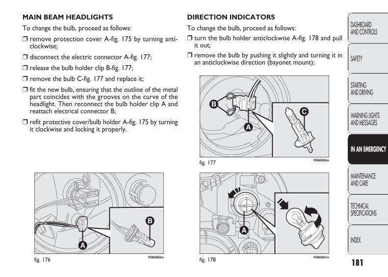
F0N0082mfig. 176 F0N0081mfig. 178
F0N0083mfig. 177
DIRECTION INDICATORS
To change the bulb, proceed as follows:❒ turn the bulb holder anticlockwise A-fig. 178 and pull
it out; ❒ remove the bulb by pushing it slightly and turning it in
an anticlockwise direction (bayonet mount);
MAIN BEAM HEADLIGHTS
To change the bulb, proceed as follows:
❒ remove protection cover A-fig. 175 by turning anti-clockwise;
❒ disconnect the electric connector A-fig. 177;
❒ release the bulb holder clip B-fig. 177;
❒ remove the bulb C-fig. 177 and replace it;
❒ fit the new bulb, ensuring that the outline of the metalpart coincides with the grooves on the curve of theheadlight. Then reconnect the bulb holder clip A andreattach electrical connector B;
❒ refit protective cover/bulb holder A-fig. 175 by turningit clockwise and locking it properly.
181
DASHBOARD AND CONTROLS
SAFETY
STARTING AND DRIVING
WARNING LIGHTSAND MESSAGES
IN AN EMERGENCY
MAINTENANCE AND CARE
TECHNICAL SPECIFICATIONS
INDEX
165-198 DUCATO LUM EN 12-02-2010 8:43 Pagina 181

F0N0084mfig. 179 F0N0169mfig. 180
❒ fit the new bulb, ensuring that the outline of the metalpart coincides with the grooves on the curve of theheadlight. Then reconnect the electrical connector Aand reattach the bulb holding clip B;
❒ refit the protective cover by turning it clockwise andlocking it properly.
SIDE LIGHTS fig. 180-181
To change the bulb, proceed as follows:
❒ move the mirror manually to access the two fixingscrews A;
❒ using a Philips screwdriver, undo the screws and extractthe bulb holder releasing it from the teeth;
❒ undo the bulb and replace bulb B by turning it in an an-ticlockwise direction.
❒ replace the bulb;
❒ refit the bulb holder by turning it clockwise and lock-ing it properly.
DIPPED HEADLAMPS
With incandescent bulbs
To change the bulb, proceed as follows:
❒ remove protection cover B-fig. 175 by turning anti-clockwise;
❒ disconnect the electric connector A-fig. 179;
❒ release the bulb holder clip B-fig. 179;
❒ remove the bulb C-fig. 179 and replace it;
182
DASHBOARD AND CONTROLS
SAFETY
STARTING AND DRIVING
WARNING LIGHTSAND MESSAGES
IN AN EMERGENCY
MAINTENANCE AND CARE
TECHNICAL SPECIFICATIONS
INDEX
165-198 DUCATO LUM EN 12-02-2010 8:43 Pagina 182

F0N0170mfig. 181
F0N0339mfig. 182
FOG LIGHTS (where provided)
To replace the front fog light bulbs A-fig. 182 proceed as follows:
❒ steer fully to the left;
❒ open the flap on the front wheel compartment guard,unscrewing the self-tapping screw;
❒ remove the bayonet cap;
❒ disconnect the connector;
❒ release the bulb holding clip;
❒ remove the bulb and replace it;
❒ fit the new bulb, ensuring that the outline of the metalpart coincides with the grooves on the curve of theheadlight. Then reconnect the bulb holder clip and reat-tach electrical connector;
❒ refit the bayonet cap.
183
DASHBOARD AND CONTROLS
SAFETY
STARTING AND DRIVING
WARNING LIGHTSAND MESSAGES
IN AN EMERGENCY
MAINTENANCE AND CARE
TECHNICAL SPECIFICATIONS
INDEX
F0N0086mfig. 183
165-198 DUCATO LUM EN 12-02-2010 8:43 Pagina 183
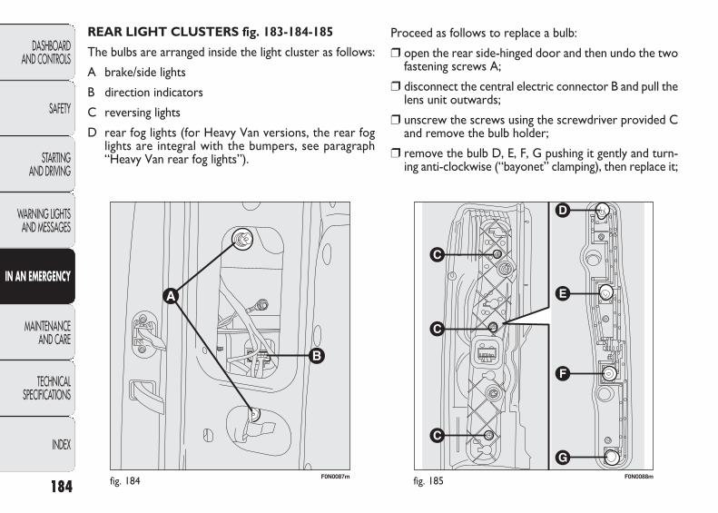
REAR LIGHT CLUSTERS fig. 183-184-185
The bulbs are arranged inside the light cluster as follows:
A brake/side lights
B direction indicators
C reversing lights
D rear fog lights (for Heavy Van versions, the rear foglights are integral with the bumpers, see paragraph“Heavy Van rear fog lights”).
184
DASHBOARD AND CONTROLS
SAFETY
STARTING AND DRIVING
WARNING LIGHTSAND MESSAGES
IN AN EMERGENCY
MAINTENANCE AND CARE
TECHNICAL SPECIFICATIONS
INDEX
F0N0087mfig. 184 F0N0088mfig. 185
Proceed as follows to replace a bulb:
❒ open the rear side-hinged door and then undo the twofastening screws A;
❒ disconnect the central electric connector B and pull thelens unit outwards;
❒ unscrew the screws using the screwdriver provided Cand remove the bulb holder;
❒ remove the bulb D, E, F, G pushing it gently and turn-ing anti-clockwise (“bayonet” clamping), then replace it;
165-198 DUCATO LUM EN 12-02-2010 8:43 Pagina 184
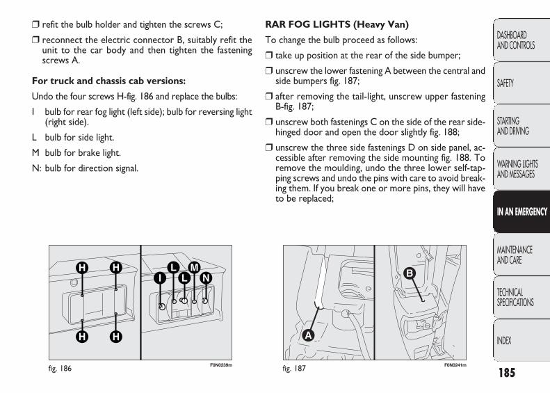
F0N0239mfig. 186 F0N0241mfig. 187
RAR FOG LIGHTS (Heavy Van)
To change the bulb proceed as follows:
❒ take up position at the rear of the side bumper;
❒ unscrew the lower fastening A between the central andside bumpers fig. 187;
❒ after removing the tail-light, unscrew upper fastening B-fig. 187;
❒ unscrew both fastenings C on the side of the rear side-hinged door and open the door slightly fig. 188;
❒ unscrew the three side fastenings D on side panel, ac-cessible after removing the side mounting fig. 188. Toremove the moulding, undo the three lower self-tap-ping screws and undo the pins with care to avoid break-ing them. If you break one or more pins, they will haveto be replaced;
❒ refit the bulb holder and tighten the screws C;
❒ reconnect the electric connector B, suitably refit theunit to the car body and then tighten the fasteningscrews A.
For truck and chassis cab versions:
Undo the four screws H-fig. 186 and replace the bulbs:
I bulb for rear fog light (left side); bulb for reversing light(right side).
L bulb for side light.
M bulb for brake light.
N: bulb for direction signal.
185
DASHBOARD AND CONTROLS
SAFETY
STARTING AND DRIVING
WARNING LIGHTSAND MESSAGES
IN AN EMERGENCY
MAINTENANCE AND CARE
TECHNICAL SPECIFICATIONS
INDEX
165-198 DUCATO LUM EN 12-02-2010 8:43 Pagina 185
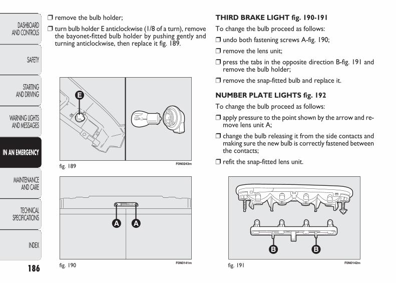
F0N0141mfig. 190
F0N0243mfig. 189
F0N0142mfig. 191
THIRD BRAKE LIGHT fig. 190-191
To change the bulb proceed as follows:
❒ undo both fastening screws A-fig. 190;
❒ remove the lens unit;
❒ press the tabs in the opposite direction B-fig. 191 andremove the bulb holder;
❒ remove the snap-fitted bulb and replace it.
NUMBER PLATE LIGHTS fig. 192
To change the bulb proceed as follows:
❒ apply pressure to the point shown by the arrow and re-move lens unit A;
❒ change the bulb releasing it from the side contacts andmaking sure the new bulb is correctly fastened betweenthe contacts;
❒ refit the snap-fitted lens unit.
❒ remove the bulb holder;
❒ turn bulb holder E anticlockwise (1/8 of a turn), removethe bayonet-fitted bulb holder by pushing gently andturning anticlockwise, then replace it fig. 189.
186
DASHBOARD AND CONTROLS
SAFETY
STARTING AND DRIVING
WARNING LIGHTSAND MESSAGES
IN AN EMERGENCY
MAINTENANCE AND CARE
TECHNICAL SPECIFICATIONS
INDEX
165-198 DUCATO LUM EN 12-02-2010 8:44 Pagina 186
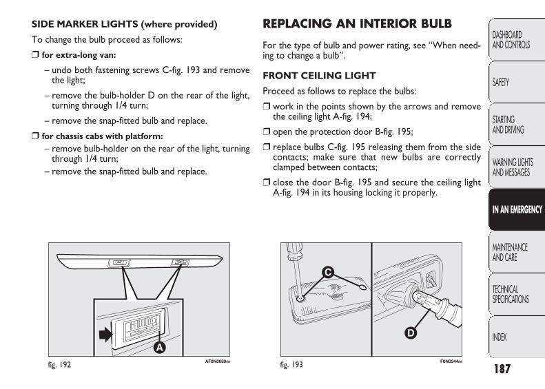
AF0N0089mfig. 192 F0N0244mfig. 193
REPLACING AN INTERIOR BULB
For the type of bulb and power rating, see “When need-ing to change a bulb”.
FRONT CEILING LIGHT
Proceed as follows to replace the bulbs:
❒ work in the points shown by the arrows and removethe ceiling light A-fig. 194;
❒ open the protection door B-fig. 195;
❒ replace bulbs C-fig. 195 releasing them from the sidecontacts; make sure that new bulbs are correctlyclamped between contacts;
❒ close the door B-fig. 195 and secure the ceiling lightA-fig. 194 in its housing locking it properly.
SIDE MARKER LIGHTS (where provided)
To change the bulb proceed as follows:
❒ for extra-long van:
– undo both fastening screws C-fig. 193 and removethe light;
– remove the bulb-holder D on the rear of the light,turning through 1/4 turn;
– remove the snap-fitted bulb and replace.
❒ for chassis cabs with platform:– remove bulb-holder on the rear of the light, turning
through 1/4 turn;– remove the snap-fitted bulb and replace.
187
DASHBOARD AND CONTROLS
SAFETY
STARTING AND DRIVING
WARNING LIGHTSAND MESSAGES
IN AN EMERGENCY
MAINTENANCE AND CARE
TECHNICAL SPECIFICATIONS
INDEX
165-198 DUCATO LUM EN 12-02-2010 8:44 Pagina 187
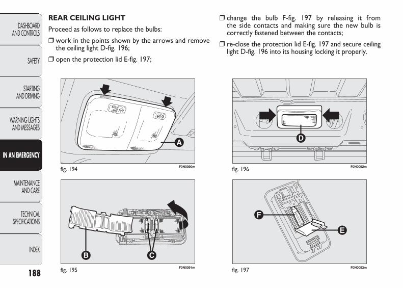
F0N0091mfig. 195
F0N0090mfig. 194
F0N0093mfig. 197
F0N0092mfig. 196
❒ change the bulb F-fig. 197 by releasing it from the side contacts and making sure the new bulb is correctly fastened between the contacts;
❒ re-close the protection lid E-fig. 197 and secure ceilinglight D-fig. 196 into its housing locking it properly.
REAR CEILING LIGHT
Proceed as follows to replace the bulbs:
❒ work in the points shown by the arrows and removethe ceiling light D-fig. 196;
❒ open the protection lid E-fig. 197;
188
DASHBOARD AND CONTROLS
SAFETY
STARTING AND DRIVING
WARNING LIGHTSAND MESSAGES
IN AN EMERGENCY
MAINTENANCE AND CARE
TECHNICAL SPECIFICATIONS
INDEX
165-198 DUCATO LUM EN 12-02-2010 8:44 Pagina 188
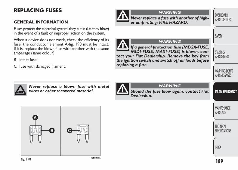
F0N0094mfig. 198
REPLACING FUSES
GENERAL INFORMATION
Fuses protect the electrical system: they cut in (i.e. they blow)in the event of a fault or improper action on the system.
When a device does not work, check the efficiency of itsfuse: the conductor element A-fig. 198 must be intact. If it is, replace the blown fuse with another with the sameamperage (same colour).
B intact fuse;
C fuse with damaged filament.
189
DASHBOARD AND CONTROLS
SAFETY
STARTING AND DRIVING
WARNING LIGHTSAND MESSAGES
IN AN EMERGENCY
MAINTENANCE AND CARE
TECHNICAL SPECIFICATIONS
INDEX
Never replace a blown fuse with metalwires or other recovered material.
Never replace a fuse with another of high-er amp rating; FIRE HAZARD.
WARNING
If a general protection fuse (MEGA-FUSE,MIDI-FUSE, MAXI-FUSE) is blown, con-
tact your Fiat Dealership. Remove the key fromthe ignition switch and switch off all loads beforereplacing a fuse.
WARNING
Should the fuse blow again, contact FiatDealership.
WARNING
165-198 DUCATO LUM EN 12-02-2010 8:44 Pagina 189
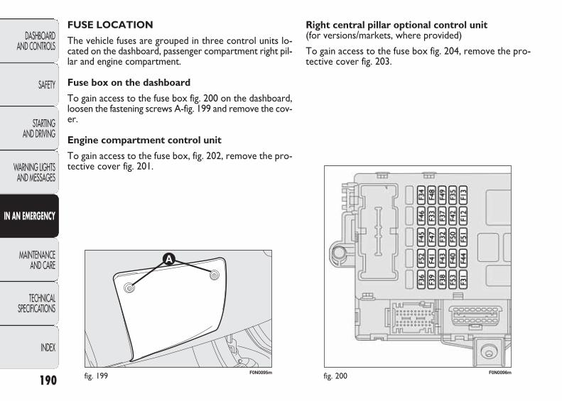
F0N0095mfig. 199 F0N0096mfig. 200
Right central pillar optional control unit (for versions/markets, where provided)
To gain access to the fuse box fig. 204, remove the pro-tective cover fig. 203.
FUSE LOCATION
The vehicle fuses are grouped in three control units lo-cated on the dashboard, passenger compartment right pil-lar and engine compartment.
Fuse box on the dashboard
To gain access to the fuse box fig. 200 on the dashboard,loosen the fastening screws A-fig. 199 and remove the cov-er.
Engine compartment control unit
To gain access to the fuse box, fig. 202, remove the pro-tective cover fig. 201.
190
DASHBOARD AND CONTROLS
SAFETY
STARTING AND DRIVING
WARNING LIGHTSAND MESSAGES
IN AN EMERGENCY
MAINTENANCE AND CARE
TECHNICAL SPECIFICATIONS
INDEX
165-198 DUCATO LUM EN 12-02-2010 8:44 Pagina 190
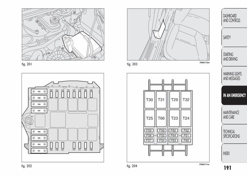
fig. 201
fig. 202
F0N0172mfig. 203
F0N0171mfig. 204 191
DASHBOARD AND CONTROLS
SAFETY
STARTING AND DRIVING
WARNING LIGHTSAND MESSAGES
IN AN EMERGENCY
MAINTENANCE AND CARE
TECHNICAL SPECIFICATIONS
INDEX
165-198 DUCATO LUM EN 12-02-2010 8:44 Pagina 191
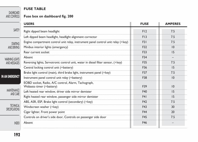
192
DASHBOARD AND CONTROLS
SAFETY
STARTING AND DRIVING
WARNING LIGHTSAND MESSAGES
IN AN EMERGENCY
MAINTENANCE AND CARE
TECHNICAL SPECIFICATIONS
INDEX
FUSE TABLE
Fuse box on dashboard fig. 200
USERS FUSE AMPERES
Right dipped beam headlight F12 7.5
Left dipped beam headlight, headlight alignment corrector F13 7.5
Engine compartment control unit relay, instrument panel control unit relay (+key) F31 7.5
Minibus interior lights (emergency) F32 10
Rear current socket F33 15
Absent F34 –
Reversing lights, Servotronic control unit, water in diesel filter sensor, (+key) F35 7.5
Central locking control unit (+battery) F36 15
Brake light control (main), third brake light, instrument panel (+key) F37 7.5
Instrument panel control unit relay (+battery) F38 10
EOBD socket, Radio, A/C control, Alarm, Tachograph, Webasto timer (+battery) F39 10
Left heated rear window, driver side mirror demister F40 15
Right heated rear window, passenger side mirror demister F41 15
ABS, ASR, ESP, Brake light control (secondary) (+key) F42 7.5
Windscreen washer (+key) F43 30
Cigar lighter, Front power point F44 20
Controls on driver’s side door, Controls on passenger side door F45 7.5
Absent F46 –
165-198 DUCATO LUM EN 12-02-2010 8:44 Pagina 192
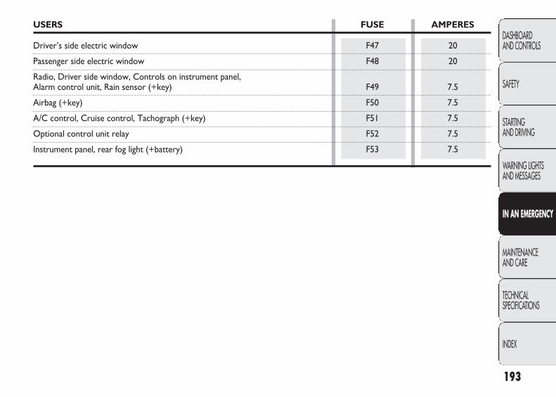
193
DASHBOARD AND CONTROLS
SAFETY
STARTING AND DRIVING
WARNING LIGHTSAND MESSAGES
IN AN EMERGENCY
MAINTENANCE AND CARE
TECHNICAL SPECIFICATIONS
INDEX
USERS FUSE AMPERES
Driver’s side electric window F47 20
Passenger side electric window F48 20
Radio, Driver side window, Controls on instrument panel, Alarm control unit, Rain sensor (+key) F49 7.5
Airbag (+key) F50 7.5
A/C control, Cruise control, Tachograph (+key) F51 7.5
Optional control unit relay F52 7.5
Instrument panel, rear fog light (+battery) F53 7.5
165-198 DUCATO LUM EN 12-02-2010 8:44 Pagina 193

194
DASHBOARD AND CONTROLS
SAFETY
STARTING AND DRIVING
WARNING LIGHTSAND MESSAGES
IN AN EMERGENCY
MAINTENANCE AND CARE
TECHNICAL SPECIFICATIONS
INDEX
Engine compartment control unit fig. 202
USERS FUSE AMPERES
ABS pump (+battery) F01 40Preheating glow plugs (+battery) F02 50Ignition switch (+battery) F03 30Webasto control unit (+battery) F04 20Passenger compartment ventilation with Webasto (+battery) F05 20Engine cooling high speed fan (+battery) F06 40/60Engine cooling low speed fan (+battery) F07 40/50Passenger compartment fan (+key) F08 40Windscreen washer pump F09 20Horn F10 15i.e. system (secondary services) F11 15Right main beam headlamp F14 7.5Left main beam headlamp F15 7.5i.e. system (+key) F16 7.5i.e. system (primary services) F17 10Engine management control unit (+battery) F18 7.5Air climate control compressor F19 7.5Headlamp washer pump F20 30Fuel pump F21 15i.e. system (primary services) F22 20ABS solenoid valves F23 30Automatic transmission 8 (+key) F24 15Fog lights F30 15
165-198 DUCATO LUM EN 12-02-2010 8:44 Pagina 194

195
DASHBOARD AND CONTROLS
SAFETY
STARTING AND DRIVING
WARNING LIGHTSAND MESSAGES
IN AN EMERGENCY
MAINTENANCE AND CARE
TECHNICAL SPECIFICATIONS
INDEX
Right central pillar optional control unit fig. 204
USERS FUSE AMPERES
Absent F54 –Heated seats F55 15Rear passenger current socket F56 15Additional heater under the seat F57 10Side lights F58 10Self-levelling suspension (+battery) F59 7.5Absent F60 –Absent F61 –Absent F62 –Additional passenger heater control F63 10Absent F64 –Additional passenger heater fan F65 30
165-198 DUCATO LUM EN 12-02-2010 8:44 Pagina 195
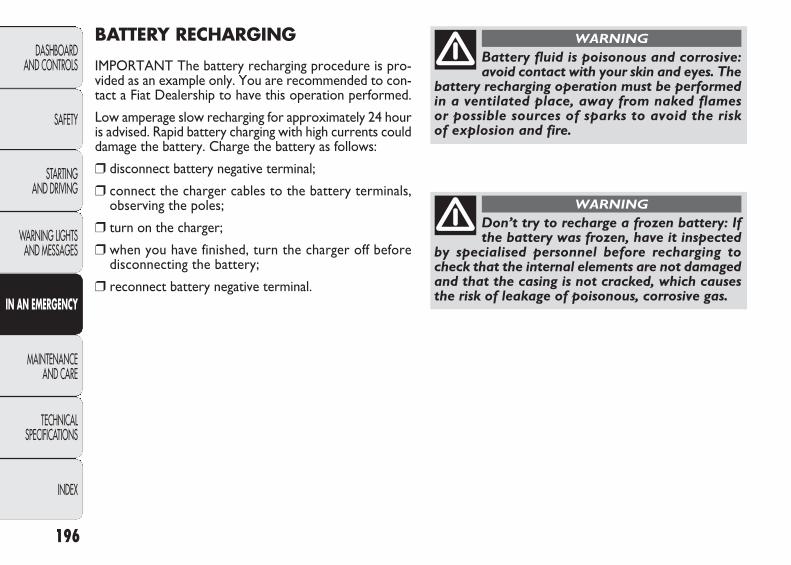
BATTERY RECHARGING
IMPORTANT The battery recharging procedure is pro-vided as an example only. You are recommended to con-tact a Fiat Dealership to have this operation performed.
Low amperage slow recharging for approximately 24 houris advised. Rapid battery charging with high currents coulddamage the battery. Charge the battery as follows:
❒ disconnect battery negative terminal;
❒ connect the charger cables to the battery terminals,observing the poles;
❒ turn on the charger;
❒ when you have finished, turn the charger off beforedisconnecting the battery;
❒ reconnect battery negative terminal.
196
DASHBOARD AND CONTROLS
SAFETY
STARTING AND DRIVING
WARNING LIGHTSAND MESSAGES
IN AN EMERGENCY
MAINTENANCE AND CARE
TECHNICAL SPECIFICATIONS
INDEX
Battery fluid is poisonous and corrosive:avoid contact with your skin and eyes. The
battery recharging operation must be performedin a ventilated place, away from naked flamesor possible sources of sparks to avoid the riskof explosion and fire.
WARNING
Don’t try to recharge a frozen battery: Ifthe battery was frozen, have it inspected
by specialised personnel before recharging tocheck that the internal elements are not damagedand that the casing is not cracked, which causesthe risk of leakage of poisonous, corrosive gas.
WARNING
165-198 DUCATO LUM EN 12-02-2010 8:44 Pagina 196
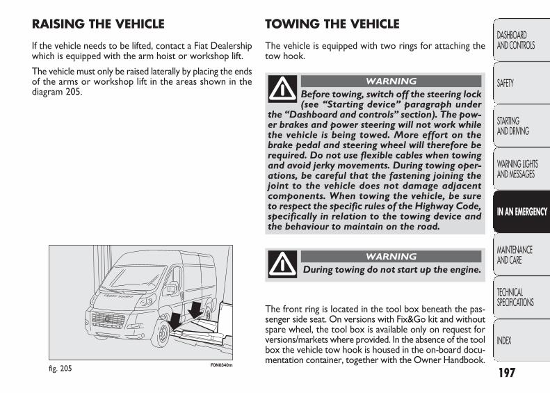
F0N0340mfig. 205
RAISING THE VEHICLE
If the vehicle needs to be lifted, contact a Fiat Dealershipwhich is equipped with the arm hoist or workshop lift.
The vehicle must only be raised laterally by placing the endsof the arms or workshop lift in the areas shown in thediagram 205.
197
DASHBOARD AND CONTROLS
SAFETY
STARTING AND DRIVING
WARNING LIGHTSAND MESSAGES
IN AN EMERGENCY
MAINTENANCE AND CARE
TECHNICAL SPECIFICATIONS
INDEX
During towing do not start up the engine.
WARNING
Before towing, switch off the steering lock(see “Starting device” paragraph under
the “Dashboard and controls” section). The pow-er brakes and power steering will not work whilethe vehicle is being towed. More effort on thebrake pedal and steering wheel will therefore berequired. Do not use flexible cables when towingand avoid jerky movements. During towing oper-ations, be careful that the fastening joining thejoint to the vehicle does not damage adjacentcomponents. When towing the vehicle, be sureto respect the specific rules of the Highway Code,specifically in relation to the towing device andthe behaviour to maintain on the road.
WARNING
TOWING THE VEHICLE
The vehicle is equipped with two rings for attaching thetow hook.
The front ring is located in the tool box beneath the pas-senger side seat. On versions with Fix&Go kit and withoutspare wheel, the tool box is available only on request forversions/markets where provided. In the absence of the toolbox the vehicle tow hook is housed in the on-board docu-mentation container, together with the Owner Handbook.
165-198 DUCATO LUM EN 12-02-2010 8:44 Pagina 197

F0N0117mfig. 209F0N0135mfig. 207
F0N0136mfig. 208
❒ take the provided screwdriver from the box and priseup at the point shown to raise the cap C-fig. 208;
❒ take the tow ring D from the box and screw it onto thethreaded pin fig. 208.
The rear ring B-fig 209 is located at the point shown in thediagram.
198
DASHBOARD AND CONTROLS
SAFETY
STARTING AND DRIVING
WARNING LIGHTSAND MESSAGES
IN AN EMERGENCY
MAINTENANCE AND CARE
TECHNICAL SPECIFICATIONS
INDEX
For activation/deactivation, proceed as follows:❒ open the flap A and remove it as illustrated in fig. 206;❒ turn the lock knob B anticlockwise and remove it
fig. 206 to allow the removal of the box fig. 207;
F0N0134mfig. 206
165-198 DUCATO LUM EN 12-02-2010 8:44 Pagina 198
199
DASHBOARD AND CONTROLS
SAFETY
STARTING AND DRIVING
WARNING LIGHTSAND MESSAGES
IN AN EMERGENCY
MAINTENANCE AND CARE
TECHNICAL SPECIFICATIONS
INDEX
MAINTENANCE AND CARE
SCHEDULED MAINTENANCE
Correct maintenance is a decisive factor in guaranteeinga long life for the vehicle in optimum conditions.
This is why Fiat has planned a series of checks and main-tenance operations every 40,000/45,000 km.
The scheduled maintenance programme does not, how-ever, cover all the vehicle requirements; during the initialperiod, before the 40,000/45,000 kilometre service andlater on, between services, routine operations must becarried out like systematically checking and topping upfluid levels, checking the tyre inflation pressure, etc.
IMPORTANT Scheduled Maintenance services are re-quired by the manufacturer. Failure to carry out these services may invalidate the warranty.
The services can be carried out by any Fiat Dealer at theappointed times.
If there is the need for further replacements or repairsduring any operation in addition to those planned, prior consent of the Customer must be obtained first.
IMPORTANT It is advisable to inform a Fiat Dealership ofany small operating irregularities without waiting for thenext service.
If your vehicle is used frequently for trailer towing, theinterval between scheduled maintenance services must bereduced.
199-222 DUCATO LUM EN 12-02-2010 12:14 Pagina 199
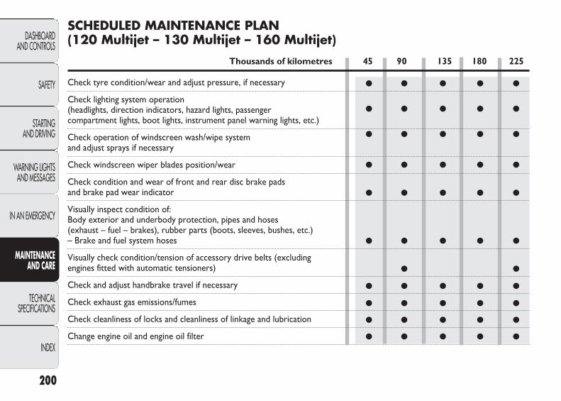
● ● ● ● ●
● ● ● ● ●
● ● ● ● ●
● ● ● ● ●
● ● ● ● ●
● ● ● ● ●
● ●
● ● ● ● ●
● ● ● ● ●
● ● ● ● ●
● ● ● ● ●
200
DASHBOARD AND CONTROLS
SAFETY
STARTING AND DRIVING
WARNING LIGHTSAND MESSAGES
IN AN EMERGENCY
MAINTENANCE AND CARE
TECHNICAL SPECIFICATIONS
INDEX
SCHEDULED MAINTENANCE PLAN (120 Multijet – 130 Multijet – 160 Multijet)
Thousands of kilometres 45 90 135 180 225
Check tyre condition/wear and adjust pressure, if necessary
Check lighting system operation (headlights, direction indicators, hazard lights, passenger compartment lights, boot lights, instrument panel warning lights, etc.)
Check operation of windscreen wash/wipe system and adjust sprays if necessary
Check windscreen wiper blades position/wear
Check condition and wear of front and rear disc brake pads and brake pad wear indicator
Visually inspect condition of:Body exterior and underbody protection, pipes and hoses (exhaust – fuel – brakes), rubber parts (boots, sleeves, bushes, etc.) – Brake and fuel system hoses
Visually check condition/tension of accessory drive belts (excluding engines fitted with automatic tensioners)
Check and adjust handbrake travel if necessary
Check exhaust gas emissions/fumes
Check cleanliness of locks and cleanliness of linkage and lubrication
Change engine oil and engine oil filter
199-222 DUCATO LUM EN 12-02-2010 12:14 Pagina 200

● ● ● ● ●
● ● ● ● ●
● ● ● ● ●
●
●
●
● ● ● ● ●
● ●
● ● ● ● ●
201
DASHBOARD AND CONTROLS
SAFETY
STARTING AND DRIVING
WARNING LIGHTSAND MESSAGES
IN AN EMERGENCY
MAINTENANCE AND CARE
TECHNICAL SPECIFICATIONS
INDEX
Thousands of kilometres 45 90 135 180 225
Replace fuel filter
Replace air filter cartridge (▼)
Check and top up, if required, fluid levels (engine coolant, brake fluid, windscreen washer fluid, battery fluid, etc);
Check timing belt (120 – 130 Multijet versions)
Replace auxiliary drive belt
Check timing drive belt (120 – 130 Multijet versions)
Check operation of engine management systems (using diagnostic socket)
Change brake fluid (or every 24 months)
Replace pollen filter (or every 24 months)
(*) Or every 4 years for heavy-duty use (cold climates, town use with long periods spent idling, use on particularly dustyroads or roads spread with sand and/or salt). Or every 5 years, regardless of the distance.
(▼) If the vehicle is equipped with a special air filter for dusty areas: – every 20,000 km check and clean filter; – every 40,000 km replace filter.
199-222 DUCATO LUM EN 12-02-2010 12:14 Pagina 201
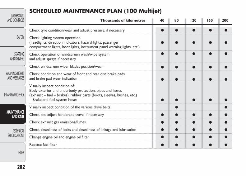
202
DASHBOARD AND CONTROLS
SAFETY
STARTING AND DRIVING
WARNING LIGHTSAND MESSAGES
IN AN EMERGENCY
MAINTENANCE AND CARE
TECHNICAL SPECIFICATIONS
INDEX
● ● ● ● ●
● ● ● ● ●
● ● ● ● ●
● ● ● ● ●
● ● ● ● ●
● ● ● ● ●
● ●
● ● ● ● ●
● ● ● ● ●
● ● ● ● ●
● ● ● ● ●
● ● ● ● ●
SCHEDULED MAINTENANCE PLAN (100 Multijet)
Thousands of kilometres 40 80 120 160 200
Check tyre condition/wear and adjust pressure, if necessary
Check lighting system operation (headlights, direction indicators, hazard lights, passenger compartment lights, boot lights, instrument panel warning lights, etc.)
Check operation of windscreen wash/wipe system and adjust sprays if necessary
Check windscreen wiper blades position/wear
Check condition and wear of front and rear disc brake pads and brake pad wear indication
Visually inspect condition of:Body exterior and underbody protection, pipes and hoses (exhaust – fuel – brakes), rubber parts (boots, sleeves, bushes, etc.) – Brake and fuel system hoses
Visually inspect condition of the various drive belts
Check and adjust handbrake travel if necessary
Check exhaust gas emissions/fumes
Check cleanliness of locks and cleanliness of linkage and lubrication
Change engine oil and engine oil filter
Replace fuel filter
199-222 DUCATO LUM EN 12-02-2010 12:14 Pagina 202
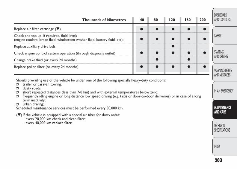
203
DASHBOARD AND CONTROLS
SAFETY
STARTING AND DRIVING
WARNING LIGHTSAND MESSAGES
IN AN EMERGENCY
MAINTENANCE AND CARE
TECHNICAL SPECIFICATIONS
INDEX
● ● ● ● ●
● ● ● ● ●
●
● ● ● ● ●
● ●
● ● ● ● ●
Thousands of kilometres 40 80 120 160 200
Replace air filter cartridge (▼)
Check and top up, if required, fluid levels (engine coolant, brake fluid, windscreen washer fluid, battery fluid, etc);
Replace auxiliary drive belt
Check engine control system operation (through diagnosis outlet)
Change brake fluid (or every 24 months)
Replace pollen filter (or every 24 months)
Should prevailing use of the vehicle be under one of the following specially heavy-duty conditions:❒ trailer or caravan towing;❒ dusty roads;❒ short repeated distances (less than 7-8 km) and with external temperatures below zero;❒ frequently idling engine or long distance low speed driving (e.g. taxis or door-to-door deliveries) or in case of a long
term inactivity;❒ urban driving;Scheduled maintenance services must be performed every 30,000 km.
(▼) If the vehicle is equipped with a special air filter for dusty areas: – every 20,000 km check and clean filter; – every 40,000 km replace filter.
199-222 DUCATO LUM EN 12-02-2010 12:14 Pagina 203
204
DASHBOARD AND CONTROLS
SAFETY
STARTING AND DRIVING
WARNING LIGHTSAND MESSAGES
IN AN EMERGENCY
MAINTENANCE AND CARE
TECHNICAL SPECIFICATIONS
INDEX
HEAVY USAGE OF THE VEHICLE
If the vehicle is mostly used in one of the following par-ticularly harsh conditions:❒ trailer or caravan towing;❒ dusty roads;❒ short repeated distances (less than 7-8 km) and with
external temperatures below zero;❒ frequently idling engine or long distance low speed dri-
ving (e.g. taxis or door-to-door deliveries) or in caseof a long term inactivity;
❒ urban driving;the following checks must be carried out more often thanindicated in the Planned Maintenance Programme:❒ check front disk brake pad conditions and wear;❒ check cleanliness of bonnet and boot locks and lever
cleanliness and lubrication;❒ sight inspect the conditions of: engine, gearbox, trans-
mission, pipes and hoses (exhaust – fuel – brakes), rub-ber parts (boots, sleeves, bushes, etc.);
❒ check battery charge and liquid level (electrolyte);❒ visual check on various drive belt conditions;❒ check pollen filter and replace it, if required;❒ check air cleaner and replace it, if required.
PERIODIC CHECKS
Every 1,000 km or before long journeys, check and, if nec-essary, restore the following:
❒ engine coolant fluid level;
❒ brake fluid level;
❒ windscreen washer fluid level;
❒ tyre pressure and conditions;
❒ operation of lights (headlights, direction indicators,emergency lights, etc.);
❒ operation of the windscreen wiper/washer system, po-sition and wear of the windscreen and rear windowwiper blades.
Every 3,000 km check and top up if required: engine oillevel.
You are recommended to use PETRONAS LUBRI-CANTS products, designed and produced specifically forFiat cars (see table “Capacities” in section “Technical Spec-ifications”).
199-222 DUCATO LUM EN 12-02-2010 12:14 Pagina 204
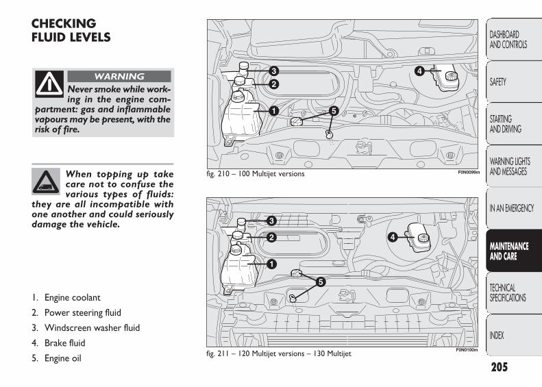
205
DASHBOARD AND CONTROLS
SAFETY
STARTING AND DRIVING
WARNING LIGHTSAND MESSAGES
IN AN EMERGENCY
MAINTENANCE AND CARE
TECHNICAL SPECIFICATIONS
INDEX
CHECKING FLUID LEVELS
fig. 210 – 100 Multijet versions
fig. 211 – 120 Multijet versions – 130 Multijet
Never smoke while work-ing in the engine com-
partment: gas and inflammablevapours may be present, with therisk of fire.
WARNING
When topping up takecare not to confuse thevarious types of fluids:
they are all incompatible withone another and could seriouslydamage the vehicle.
1. Engine coolant
2. Power steering fluid
3. Windscreen washer fluid
4. Brake fluid
5. Engine oil
F0N0099m
F0N0100m
199-222 DUCATO LUM EN 12-02-2010 12:14 Pagina 205
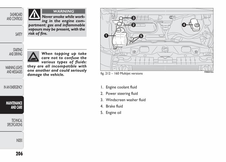
206
DASHBOARD AND CONTROLS
SAFETY
STARTING AND DRIVING
WARNING LIGHTSAND MESSAGES
IN AN EMERGENCY
MAINTENANCE AND CARE
TECHNICAL SPECIFICATIONS
INDEX
When topping up takecare not to confuse thevarious types of fluids:
they are all incompatible withone another and could seriouslydamage the vehicle.
1. Engine coolant fluid
2. Power steering fluid
3. Windscreen washer fluid
4. Brake fluid
5. Engine oil
fig. 212 – 160 Multijet versions
Never smoke while work-ing in the engine com-
partment: gas and inflammablevapours may be present, with therisk of fire.
WARNING
F0N0210m
199-222 DUCATO LUM EN 12-02-2010 12:14 Pagina 206

207
DASHBOARD AND CONTROLS
SAFETY
STARTING AND DRIVING
WARNING LIGHTSAND MESSAGES
IN AN EMERGENCY
MAINTENANCE AND CARE
TECHNICAL SPECIFICATIONS
INDEX
F0N0101mfig. 213 – 100 Multijet versions
F0N0211mfig. 215 – 160 Multijet versions
F0N0102mfig. 214 – 120 – 130 Multijet versions
ENGINE OIL CONSUMPTION
The maximum engine oil consumption is usually 400 gramsevery 1000 km.
When the vehicle is new, the engine needs to be runin, therefore the engine oil consumption can only be considered stabilised after the first 5,000÷6,000 km.
ENGINE OIL fig. 213-214-215
Check the oil level a few minutes (about 5) after the en-gine has stopped, with the vehicle parked on level ground.
The oil level should be between the MIN and MAX markson the dipstick B.
The range between the MIN and MAX marks correspondsto about 1 litre of oil.
If the oil level is near or under the MIN line, add oil throughthe filler A to reach the MAX line.
The oil level should never exceed the MAX line.
199-222 DUCATO LUM EN 12-02-2010 12:14 Pagina 207
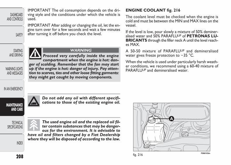
208
DASHBOARD AND CONTROLS
SAFETY
STARTING AND DRIVING
WARNING LIGHTSAND MESSAGES
IN AN EMERGENCY
MAINTENANCE AND CARE
TECHNICAL SPECIFICATIONS
INDEX
F0N0103mfig. 216
ENGINE COOLANT fig. 216
The coolant level must be checked when the engine iscold and must be between the MIN and MAX lines on thevessel.
If the level is low, pour slowly a mixture of 50% deminer-alised water and 50% PARAFLUUP of PETRONAS LU-BRICANTS through the filler neck A until the level reach-es MAX.
A 50-50 mixture of PARAFLUUP and demineralised water gives freeze protection to −35 °C.
When the vehicle is used under particularly harsh weath-er conditions, we recommend using a 60-40 mixture ofPARAFLUUP and demineralised water.
IMPORTANT The oil consumption depends on the dri-ving style and the conditions under which the vehicle isused.
IMPORTANT After adding or changing the oil, let the en-gine turn over for a few seconds and wait a few minutesafter turning it off before you check the level.
Proceed very carefully inside the enginecompartment when the engine is hot: dan-
ger of scalding. Remember that the fan may startup if the engine is hot: danger of injury. Pay atten-tion to scarves, ties and other loose fitting garments:they might get caught by moving components.
WARNING
Do not add any oil with different specifi-cations to those of the existing engine oil.
The used engine oil and the replaced oil fil-ter contain substances that may be danger-ous for the environment. It is advisable to
have oil and filters changed by a Fiat Dealershipwhere they will be disposed of according to the law.
199-222 DUCATO LUM EN 12-02-2010 12:14 Pagina 208
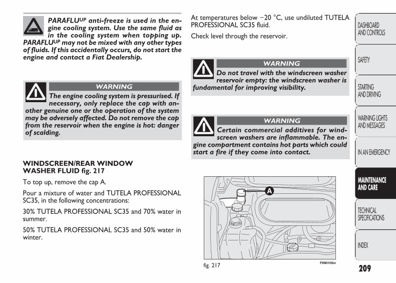
209
DASHBOARD AND CONTROLS
SAFETY
STARTING AND DRIVING
WARNING LIGHTSAND MESSAGES
IN AN EMERGENCY
MAINTENANCE AND CARE
TECHNICAL SPECIFICATIONS
INDEX
F0N0105mfig. 217
At temperatures below −20 °C, use undiluted TUTELAPROFESSIONAL SC35 fluid.
Check level through the reservoir.
PARAFLUUP anti-freeze is used in the en-gine cooling system. Use the same fluid asin the cooling system when topping up.
PARAFLUUP may not be mixed with any other typesof fluids. If this accidentally occurs, do not start theengine and contact a Fiat Dealership.
The engine cooling system is pressurised. Ifnecessary, only replace the cap with an-
other genuine one or the operation of the systemmay be adversely affected. Do not remove the capfrom the reservoir when the engine is hot: dangerof scalding.
WARNING
WINDSCREEN/REAR WINDOW WASHER FLUID fig. 217
To top up, remove the cap A.
Pour a mixture of water and TUTELA PROFESSIONALSC35, in the following concentrations:
30% TUTELA PROFESSIONAL SC35 and 70% water insummer.
50% TUTELA PROFESSIONAL SC35 and 50% water inwinter.
Do not travel with the windscreen washerreservoir empty: the windscreen washer is
fundamental for improving visibility.
WARNING
Certain commercial additives for wind-screen washers are inflammable. The en-
gine compartment contains hot parts which couldstart a fire if they come into contact.
WARNING
199-222 DUCATO LUM EN 12-02-2010 12:14 Pagina 209
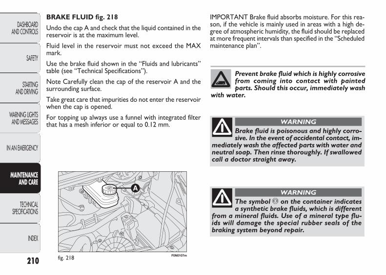
210
DASHBOARD AND CONTROLS
SAFETY
STARTING AND DRIVING
WARNING LIGHTSAND MESSAGES
IN AN EMERGENCY
MAINTENANCE AND CARE
TECHNICAL SPECIFICATIONS
INDEX
F0N0107mfig. 218
IMPORTANT Brake fluid absorbs moisture. For this rea-son, if the vehicle is mainly used in areas with a high de-gree of atmospheric humidity, the fluid should be replacedat more frequent intervals than specified in the “Scheduledmaintenance plan”.
BRAKE FLUID fig. 218
Undo the cap A and check that the liquid contained in thereservoir is at the maximum level.
Fluid level in the reservoir must not exceed the MAXmark.
Use the brake fluid shown in the “Fluids and lubricants”table (see “Technical Specifications”).
Note Carefully clean the cap of the reservoir A and thesurrounding surface.
Take great care that impurities do not enter the reservoirwhen the cap is opened.
For topping up always use a funnel with integrated filterthat has a mesh inferior or equal to 0.12 mm.
Prevent brake fluid which is highly corrosivefrom coming into contact with paintedparts. Should this occur, immediately wash
with water.
Brake fluid is poisonous and highly corro-sive. In the event of accidental contact, im-
mediately wash the affected parts with water andneutral soap. Then rinse thoroughly. If swallowedcall a doctor straight away.
WARNING
The symbol π on the container indicatesa synthetic brake fluids, which is different
from a mineral fluids. Use of a mineral type flu-ids will damage the special rubber seals of thebraking system beyond repair.
WARNING
199-222 DUCATO LUM EN 12-02-2010 12:14 Pagina 210

211
DASHBOARD AND CONTROLS
SAFETY
STARTING AND DRIVING
WARNING LIGHTSAND MESSAGES
IN AN EMERGENCY
MAINTENANCE AND CARE
TECHNICAL SPECIFICATIONS
INDEX
F0N0109mfig. 219
POWER STEERING FLUID fig. 219
Check that the liquid contained in the tank is at the max-imum level. This operation must be carried out with thevehicle level and with the engine off and cold. Check thatthe fluid level is up to the MAX mark on the dipstick at-tached to the fuel cap (use the level shown on the 20 °Cside of the dipstick to check when cold).
If the level of the fluid in the tank is lower than the spec-ified level, top up using only one of the products indicat-ed in the “Fluid and lubricants” table in the “Technicalspecifications” section, proceeding as follows:
❒ Start the engine and wait for the level of fluid in thetank to stabilise.
Power steering fluid consumption is verylow. If the fluid needs topping up a shorttime after the last top-up, have the system
checked by a Fiat Dealership to ensure there are noleaks.
Do not press the power steering end of trav-el lock for longer than 8 consecutive sec-onds with the engine running because it will
cause noise and risk damaging the system.
❒ With the engine running, turn the steering wheel fromright to left fully, several times.
❒ Top up the fuel to the MAX level and then retightenthe cap.
Prevent power steering fluid from com-ing into contact with hot engine parts:
the liquid is flammable.
WARNING
199-222 DUCATO LUM EN 12-02-2010 12:14 Pagina 211
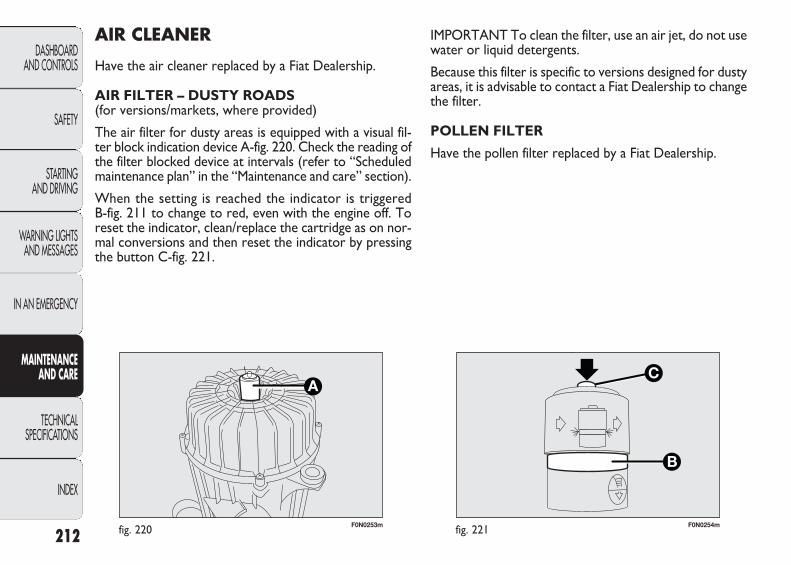
212
DASHBOARD AND CONTROLS
SAFETY
STARTING AND DRIVING
WARNING LIGHTSAND MESSAGES
IN AN EMERGENCY
MAINTENANCE AND CARE
TECHNICAL SPECIFICATIONS
INDEX
F0N0253mfig. 220 F0N0254mfig. 221
IMPORTANT To clean the filter, use an air jet, do not usewater or liquid detergents.
Because this filter is specific to versions designed for dustyareas, it is advisable to contact a Fiat Dealership to changethe filter.
POLLEN FILTER
Have the pollen filter replaced by a Fiat Dealership.
AIR CLEANER
Have the air cleaner replaced by a Fiat Dealership.
AIR FILTER – DUSTY ROADS (for versions/markets, where provided)
The air filter for dusty areas is equipped with a visual fil-ter block indication device A-fig. 220. Check the reading ofthe filter blocked device at intervals (refer to “Scheduledmaintenance plan” in the “Maintenance and care” section).
When the setting is reached the indicator is triggered B-fig. 211 to change to red, even with the engine off. Toreset the indicator, clean/replace the cartridge as on nor-mal conversions and then reset the indicator by pressingthe button C-fig. 221.
199-222 DUCATO LUM EN 12-02-2010 12:14 Pagina 212
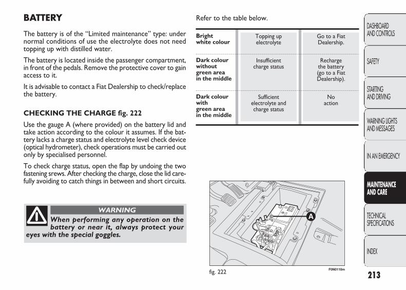
213
DASHBOARD AND CONTROLS
SAFETY
STARTING AND DRIVING
WARNING LIGHTSAND MESSAGES
IN AN EMERGENCY
MAINTENANCE AND CARE
TECHNICAL SPECIFICATIONS
INDEX
F0N0110mfig. 222
BATTERY
The battery is of the “Limited maintenance” type: undernormal conditions of use the electrolyte does not needtopping up with distilled water.
The battery is located inside the passenger compartment,in front of the pedals. Remove the protective cover to gainaccess to it.
It is advisable to contact a Fiat Dealership to check/replacethe battery.
CHECKING THE CHARGE fig. 222
Use the gauge A (where provided) on the battery lid andtake action according to the colour it assumes. If the bat-tery lacks a charge status and electrolyte level check device(optical hydrometer), check operations must be carried outonly by specialised personnel.
To check charge status, open the flap by undoing the twofastening srews. After checking the charge, close the lid care-fully avoiding to catch things in between and short circuits.
Topping up electrolyte
Insufficient charge status
Sufficient electrolyte and charge status
Go to a Fiat Dealership.
Recharge the battery (go to a Fiat Dealership).
No action
When performing any operation on thebattery or near it, always protect your
eyes with the special goggles.
WARNING
Refer to the table below.
Bright white colour
Dark colour without green area in the middle
Dark colour with green area in the middle
199-222 DUCATO LUM EN 12-02-2010 12:14 Pagina 213
214
DASHBOARD AND CONTROLS
SAFETY
STARTING AND DRIVING
WARNING LIGHTSAND MESSAGES
IN AN EMERGENCY
MAINTENANCE AND CARE
TECHNICAL SPECIFICATIONS
INDEX
Incorrect assembly of electric and electronicdevices may cause severe damage to yourvehicle. Contact a Fiat Dealership if you
want to install accessories (alarms, radiophone,etc.): they will suggest the most suitable devices andadvise you if a higher capacity battery needs to beinstalled.
If the vehicle needs to be off the road fora long period under conditions of intensecold, remove the battery and take it to a
heated place, otherwise it may freeze.
Batteries contain very dangerous sub-stances for the environment. You are rec-ommended to contact a Fiat Dealership to
have the battery replaced where the old battery willbe disposed of respecting both the environment andthe laws in force.
Battery liquid is poisonous and corrosive.Avoid contact with the skin and eyes. Keep
naked flames or possible sources of sparks awayfrom the battery: risk of explosion or fire.
WARNING
Using the battery when the fluid is too lowcan damage it irreparably and generate
a risk of explosion.
WARNING
CHANGING THE BATTERY
If required, replace the battery with a genuine spare parthaving the same specifications.
If a battery with different specifications is fitted, the ser-vice intervals given in the “Scheduled Maintenance Plan”in this section will no longer be valid.
Follow the battery manufacturer’s instructions for main-tenance.
199-222 DUCATO LUM EN 12-02-2010 12:14 Pagina 214
215
DASHBOARD AND CONTROLS
SAFETY
STARTING AND DRIVING
WARNING LIGHTSAND MESSAGES
IN AN EMERGENCY
MAINTENANCE AND CARE
TECHNICAL SPECIFICATIONS
INDEX
❒ before performing any operation on the electrical system, disconnect the battery negative cable;
❒ battery terminals shall always be perfectly tightened.
IMPORTANT A battery which is kept at a charge of lessthan 50% (optical indicator with dark colour without greenarea in the middle) for any length of time will be damagedby sulphating leading to a reduction in cranking power.
The battery will also be more at risk of freezing (e.g. al-ready at −10 °C). Refer to the paragraph “Vehicle inac-tivity” in “Starting and driving” if the car is left parked fora long time.
If, after buying the vehicle, you want to install electric ac-cessories which require permanent electric supply (alarm,etc.) contact the Fiat Dealership whose qualified person-nel, in addition to suggesting the most suitable devices ofthe Lineaccessori Fiat, will evaluate the overall electric ab-sorption, checking whether the vehicle electric system iscapable of withstanding the load required, or whether itshould be integrated with a more powerful battery.
Since these devices continue absorbing energy even whenthe ignition key is off, they gradually run down the battery.
IMPORTANT Check the battery charge once a year,preferably before the beginning of the winter, to preventfreezing of the electrolyte. This check should be carriedout more often if the vehicle is mainly used for shortjournies or if it is equipped with consumers that perma-nently absorb energy with the ignition off, especially if theyhave been fitted in the after market.
IMPORTANT If a tachograph is fitted, if the vehicle isparked up for a long period of 5 days, it is advisable todisconnect the battery negative terminal to maintain itscharge.
If the vehicle is equipped with a battery disconnectionfunction (disconnector), see the description of the pro-cedure in the “Controls” paragraph in the “Dashboardand controls” section.
USEFUL ADVICE FOR LENGTHENING THE LIFE OF YOUR BATTERY
To avoid draining your battery and make it last longer, observe the following instructions:
❒ when you park the vehicle, ensure the doors, tail-gate and bonnet are closed properly to avoid that theceiling lights remain on;
❒ the ceiling lights must be off. The vehicle is howeverprovided with an automatic system for switching offinternal lights;
❒ with the engine off, do not leave devices on for longperiods (e.g. radio, hazard lights etc.);
199-222 DUCATO LUM EN 12-02-2010 12:14 Pagina 215

216
DASHBOARD AND CONTROLS
SAFETY
STARTING AND DRIVING
WARNING LIGHTSAND MESSAGES
IN AN EMERGENCY
MAINTENANCE AND CARE
TECHNICAL SPECIFICATIONS
INDEX
F0N0111mfig. 223
IMPORTANT NOTES
❒ Avoid braking suddenly, burning starts and violentknocks against the curb, potholes or other obstaclesif possible. Long distances on rough roads may damagethe tyres;
❒ Check the tyres regularly for cuts on the sides, swellingor irregular tread wear. Contact a Fiat Dealership ifrequired;
❒ Avoid overloading the car when travelling: this maycause serious damage to the wheels and tyres;
❒ If a tyre is punctured, stop the vehicle immediatelyand change it to avoid damage to the tyre, the rim,the suspensions and the steering system;
❒ A tyre will age even if it is not used much. Cracks inthe tread and on the sidewalls are a sign of ageing. Havethe tyres checked by specialised personnel if they havebeen fitted for longer than 6 years. Remember to checkalso the spare wheel very carefully;
❒ In case of replacement, always fit new tyres, avoidingthose with an unknown origin;
❒ If a tyre is replaced, also change the inflation valve;
❒ To allow an even wear between the front and rear tyres,it is advisable to change them over every 10-15 thou-sand kilometres, keeping them on the same side of thevehicle so as not to reverse the direction of rotation.
WHEELS AND TYRES
Check the pressure of each tyre, including the spare, everytwo weeks and before long journeys. The pressure shouldbe checked with the tyre rested and cold. It is normalfor the pressure to increase when the vehicle is used;for the correct tyre inflation pressure, see “Wheels” in“Technical specifications” section. Incorrect pressurecauses abnormal tyre wear fig. 223:
A normal pressure: tread evenly worn.
B low pressure: tread particularly worn at the edges.
C high pressure: tread particularly worn in the centre.
The tyres must be replaced when the tread is less than1.6 mm thick. In all cases, follow the laws in force in thecountry where you are driving.
199-222 DUCATO LUM EN 12-02-2010 12:14 Pagina 216

217
DASHBOARD AND CONTROLS
SAFETY
STARTING AND DRIVING
WARNING LIGHTSAND MESSAGES
IN AN EMERGENCY
MAINTENANCE AND CARE
TECHNICAL SPECIFICATIONS
INDEX
RUBBER HOSES
As far as the brake system and fuel rubber hoses are con-cerned, follow the “Scheduled Maintenance Plan” in thissection carefully.
Ozone, high temperatures and prolonged lack of fluid inthe system may cause hardening and cracking of the hoses,with possible leaks.
Careful inspections are therefore necessary.
Remember that the road holding qualitiesof your vehicle also depend on the correct
inflation pressure of the tyres.
WARNING
If the pressure is too low the tyre will get overheated, with the risk of serious
damages.
WARNING
Avoid moving the tyres from the right sideof the vehicle to the left side and vice
versa. Do not repaint alloy wheel rims which needtemperatures higher than 150°C. The mechanicalcharacteristics of the wheels might be disrupted.
WARNING
199-222 DUCATO LUM EN 12-02-2010 12:14 Pagina 217

218
DASHBOARD AND CONTROLS
SAFETY
STARTING AND DRIVING
WARNING LIGHTSAND MESSAGES
IN AN EMERGENCY
MAINTENANCE AND CARE
TECHNICAL SPECIFICATIONS
INDEX
F0N0137mfig. 224
Replacing the windscreen wiper blades fig. 224
Proceed as follows:
❒ lift the arm A of the wiper and position the blade sothat it forms an angle of 90° with the arm;
❒ remove from arm A the press-fitted blade B;
❒ insert the new blade making sure it is locked.
SPRAY NOZZLES
Windscreen washer fig. 225
If the jet of fluid is inadequate, firstly check that there isfluid in the reservoir (see “Checking fluid levels” in thissection).
WINDSCREEN WIPER
BLADES
Periodically clean the rubber part using special products;TUTELA PROFESSIONAL SC 35 is recommended.
Replace the blades if the rubber edge is deformed or worn.In all cases, it is advisable to replace them approximatelyonce a year.
A few simple precautions can reduce the possibility of damage to the blades:
❒ make sure that the rubber part is not stuck to the wind-screen at sub-zero temperatures. Use an antifreezeproduct to release it if required;
❒ remove any snow from the glass: in addition to pro-tecting the blades, this prevents effort on the motorand overheating;
❒ do not operate the windscreen wipers on dry glass.
Driving with worn wiper blades is a serioushazard, because visibility is reduced in bad
weather.
WARNING
199-222 DUCATO LUM EN 12-02-2010 12:14 Pagina 218
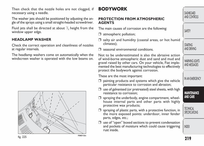
219
DASHBOARD AND CONTROLS
SAFETY
STARTING AND DRIVING
WARNING LIGHTSAND MESSAGES
IN AN EMERGENCY
MAINTENANCE AND CARE
TECHNICAL SPECIFICATIONS
INDEX
F0N0112mfig. 225
BODYWORK
PROTECTION FROM ATMOSPHERICAGENTS
The main causes of corrosion are the following:
❒ atmospheric pollution;
❒ salty air and humidity (coastal areas, or hot humid climates);
❒ seasonal environmental conditions.
Not to be underestimated is also the abrasive actionof wind-borne atmospheric dust and sand and mud andgravel raised by other cars. On your vehicle, Fiat imple-mented the best manufacturing technologies to effectivelyprotect the bodywork against corrosion.
These are the most important:❒ painting products and systems which give the vehicle
particular resistance to corrosion and abrasion;❒ use of galvanised (or pretreated) steel sheets, with high
resistance to corrosion;❒ spraying the underbody, engine compartment, wheel-
house internal parts and other parts with highly protective wax products;
❒ spraying of plastic parts, with a protective function, inthe more exposed points: underdoor, inner fenderparts, edges, etc.;
❒ use of “open” boxed sections to prevent condensationand pockets of moisture which could cause triggeringrust inside.
Then check that the nozzle holes are not clogged, if necessary using a needle.
The washer jets should be positioned by adjusting the an-gle of the sprays using a small straight-headed screwdriver.
Fluid jets shall be directed at about 1/3 height from thewindow upper edge.
HEADLAMP WASHER
Check the correct operation and cleanliness of nozzlesat regular intervals.
The headlamp washers come on automatically when thewindscreen washer is operated with the low beams on.
199-222 DUCATO LUM EN 12-02-2010 12:14 Pagina 219
220
DASHBOARD AND CONTROLS
SAFETY
STARTING AND DRIVING
WARNING LIGHTSAND MESSAGES
IN AN EMERGENCY
MAINTENANCE AND CARE
TECHNICAL SPECIFICATIONS
INDEX
❒ wipe a sponge with a slightly soapy solution over thebodywork, frequently rinsing with the sponge;
❒ rinse well with water and dry with a jet of air ora chamois leather.
Dry the less visible parts particularly carefully, such as thedoor frames, bonnet and the headlight frames, where wa-ter may stagnate more easily. It is a good idea to leavethe vehicle outdoors for a while after washing it to givewater time to evaporate.
Do not wash the vehicle after it has been left in the sunor with the bonnet hot: this may alter the shine of thepaintwork.
Exterior plastic parts must be cleaned in the same way asthe rest of the vehicle.
Where possible, do not park the vehicle under trees; theresinous substance released by many species give the painta dull appearance and increase the possibility of triggeringrust processes.
To protect the paint more effectively, polish occasionallywith special protective waxes; when the paint tends tocloud because of a build-up of smog, polish with slightlyabrasive protective waxes.
IMPORTANT Bird droppings must be washed off immediately and thoroughly as the acid they contain isparticularly aggressive.
VEHICLE BODY AND UNDERBODY WARRANTY
Your vehicle is covered by warranty against perforationdue to rust of any original element of the structure orbody.
For the general terms of this warranty, refer to Fiat Warranty Booklet.
ADVICE FOR PRESERVING THE BODYWORK
Paint
Paintwork does not only serve an aesthetic purpose, butalso protects the underlying sheet metal. Touch up abra-sions and scratches immediately to prevent rust forma-tion. Only use genuine spare paint products for touch-ups(see “Bodywork paint identification plate” in the “Tech-nical Specifications” section). Normal maintenance of paint-work consists in washing the car: the frequency dependson the conditions and environment where the car is used.For example, it is advisable to wash the vehicle more of-ten in areas with a high environmental pollution or onroads sprinkled with salt.
To correctly wash the vehicle proceed as follows:
❒ remove the aerial from the roof to prevent damageto it if the vehicle is washed in an automatic system;
❒ wash the body using a low pressure jet of water;
199-222 DUCATO LUM EN 12-02-2010 12:14 Pagina 220
221
DASHBOARD AND CONTROLS
SAFETY
STARTING AND DRIVING
WARNING LIGHTSAND MESSAGES
IN AN EMERGENCY
MAINTENANCE AND CARE
TECHNICAL SPECIFICATIONS
INDEX
INTERIORS
Periodically check that water is not trapped under the mats(due to water dripping off shoes, umbrellas, etc.) whichcould cause oxidisation of the sheet metal.
Detergents pollute the environment. Thevehicle should be washed in areas equippedfor collecting and purifying the liquid used
in the washing process.
Glasses
Use specific window cleaner products. Also use cleancloths to avoid scratching the glass or damaging thetransparency.
IMPORTANT Wipe the rear window inside gently witha cloth in the direction of the filaments to avoid damagingthe heating device.
Engine compartment
Wash the engine compartment carefully after the end ofthe winter. Be careful not to direct the jet of water ontoelectronic control units. Adequately protect the upper airvents to prevent damage to the windscreen wiper motor.Have this operation performed at a specialised workshop.
IMPORTANT The washing should take place with the en-gine cold and the ignition key in the STOP position. Af-ter the washing operation, make sure that the various pro-tections (e.g. rubber caps and guards) have not beenremoved or damaged.
Front headlights
IMPORTANT Never use aromatic substances (e.g.: petrol)or ketenes (e.g.: acetone) for cleaning front headlight plastic lens.
Never use flammable products, such aspetrol, ether or rectified petrol, to clean
the vehicle interior. The electrostatic charges whichare generated by rubbing during the cleaning operation may cause a fire.
WARNING
Do not keep aerosol cans in the vehicle: riskof explosion Aerosol cans must not be ex-
posed to a temperature exceeding 50°C. When thevehicle is exposed to sunlight, inner temperaturecan greatly exceed this value.
WARNING
199-222 DUCATO LUM EN 12-02-2010 12:14 Pagina 221

222
DASHBOARD AND CONTROLS
SAFETY
STARTING AND DRIVING
WARNING LIGHTSAND MESSAGES
IN AN EMERGENCY
MAINTENANCE AND CARE
TECHNICAL SPECIFICATIONS
INDEX
INTERIOR PLASTIC PARTS
It is advisable to clean interior parts with a moist cloth anda solution of water and mild soap. Use specific productsfor cleaning plastic, without solvents and specifically de-signed to prevent damage to the appearance and colourof the treated parts to remove grease and tough stains.
IMPORTANT Never use spirit or petroleum to clean theinstrument panel.
LEATHER STEERING WHEEL/GEAR KNOB
These components must be cleaned with mild soap andwater only.
Never use spirit and/or alcohol based products.
Before using off-the-shelves products designed for clean-ing car interiors, make sure that they do not contain spir-it and/or alcohol based substances before using them.
If window cleaner accidentally drips onto the steeringwheel or gear lever knob, wipe away immediately and thenwash the concerned area with mild soap and water.
IMPORTANT Be carefully when arranging a steering wheellock device, where applicable, to prevent damaging theleather upholstery by rubbing.
CLEANING SEATS AND FABRIC PARTS
Remove dust with a soft brush or a vacuum cleaner. It isadvisable to use a moist brush on velvet upholstery.
Rub the seats with a sponge moistened with a solution ofwater and neutral detergent.
The fabric upholstery of your vehicle is de-signed to withstand the normal wear andtear of your vehicle for a long time. Some
precautions are however needed. Avoid prolongedrubbing against clothing accessories, such as met-al buckles, Velcro strips and the like, which by ap-plying a high pressure on the fabric in a small areacould cause the breakage of some threads anddamage the upholstery.
199-222 DUCATO LUM EN 12-02-2010 12:14 Pagina 222

223
DASHBOARD AND CONTROLS
SAFETY
STARTING AND DRIVING
WARNING LIGHTSAND MESSAGES
IN AN EMERGENCY
MAINTENANCE AND CARE
TECHNICAL SPECIFICATIONS
INDEX
F0N0333mfig. 226
H Maximum authorised weight on second axle (rear)
I Engine type
L Bodywork version code
M Spares number
N Correct fume coefficient value.
TECHNICAL SPECIFICATIONS
IDENTIFICATION DATA
Take note of the identification codes. The following iden-tification codes are printed and shown on the plates:
❒ Model plate.
❒ Chassis marking.
❒ Bodywork paint identification plate.
❒ Engine marking.
MODEL PLATE fig. 226
This plate is fitted to the engine compartment front cross-member and contains the following identification data:
B Type-approval number
C Vehicle type identification code
D Chassis progressive number
E Maximum authorised weight of vehicle fully laden
F Maximum authorised weight of vehicle fully laden plustrailer
G Maximum authorised weight on first axle (front)
223-276 DUCATO LUM EN 12-02-2010 13:09 Pagina 223
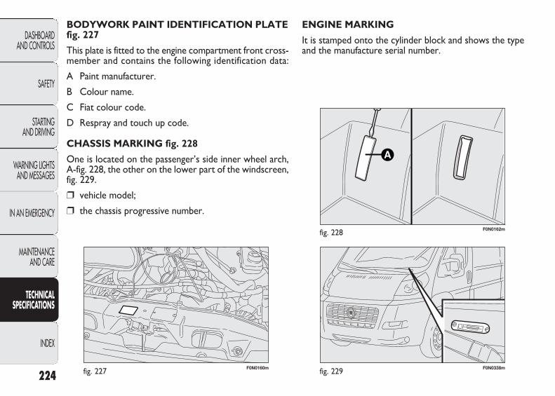
224
DASHBOARD AND CONTROLS
SAFETY
STARTING AND DRIVING
WARNING LIGHTSAND MESSAGES
IN AN EMERGENCY
MAINTENANCE AND CARE
TECHNICAL SPECIFICATIONS
INDEX
F0N0160mfig. 227 F0N0338mfig. 229
F0N0162mfig. 228
ENGINE MARKING
It is stamped onto the cylinder block and shows the typeand the manufacture serial number.
BODYWORK PAINT IDENTIFICATION PLATEfig. 227
This plate is fitted to the engine compartment front cross-member and contains the following identification data:
A Paint manufacturer.
B Colour name.
C Fiat colour code.
D Respray and touch up code.
CHASSIS MARKING fig. 228
One is located on the passenger’s side inner wheel arch,A-fig. 228, the other on the lower part of the windscreen,fig. 229.
❒ vehicle model;
❒ the chassis progressive number.
223-276 DUCATO LUM EN 12-02-2010 13:09 Pagina 224

225
DASHBOARD AND CONTROLS
SAFETY
STARTING AND DRIVING
WARNING LIGHTSAND MESSAGES
IN AN EMERGENCY
MAINTENANCE AND CARE
TECHNICAL SPECIFICATIONS
INDEX
ENGINE CODES – BODYWORK VERSIONS
Versions Engine code
100 Multijet 4HV
120 Multijet SOFIM F1AE0481D
130 Multijet SOFIM F1AE0481N
160 Multijet SOFIM F1CE0481D
There is an example of the bodywork version codes below by way of explanation with the key which is valid for allbodywork version codes:
Key 250 A A M F A AX
MODEL
PAYLOAD
ENGINE
ENGINE TRANSMISSION/AXLES
BODYWORK
WHEELBASE
VERSION
PAYLOADA 3000 kgB 3300 kgC 3500 kg LIGHTD 3500 kg HEAVYE 4005 kg
TRANSMISSION UNITM Manual gearboxA Automatic
transmission
ENGINEA 100 MultijetC 120 MultijetD 160 MultijetE 130 Multijet
WHEELBASEA Short wheelbaseB Medium wheelbaseC Long wheelbaseD Medium-long
wheelbase
BODYWORKA Chassis cab frameB Platform frame without drive cabC Platform chassis cabD Flatbed truckE Primary school busF VanG Long cab trailerH Long cab frameL Secondary school busM Minibus P PanoramaR 6/9 seater crew cabU Chassis without “floor” cab
223-276 DUCATO LUM EN 12-02-2010 13:09 Pagina 225

100 Multijet
4HV
Diesel
4 in line
86 × 94.6
2198
17.5
74100
2900
250
1500
120 Multijet
Sofim F1AE0481D
Diesel
4 in line
88 × 94
2287
19 ± 0.5
88120
3600
320
2000
130 Multijet
Sofim F1AE0481N
Diesel
4 in line
88 × 94
2287
19 ± 0.5
95.5130
3600
320
2000
160 Multijet
Sofim F1CE0481D
Diesel
4 in line
95.8 × 10⁴
2999
19
115.5157
3500
400
1600
ENGINE
GENERAL INFORMATION
Engine code
Cycle
Cylinder number and position
Piston bore and stroke mm
Total displacement cm3
Compression ratio:
Max power (EEC) kW
HP corresponding speed rpm
Maximum torque (EEC) Nm
corresponding speed rpm
Fuel
226
DASHBOARD AND CONTROLS
SAFETY
STARTING AND DRIVING
WARNING LIGHTSAND MESSAGES
IN AN EMERGENCY
MAINTENANCE AND CARE
TECHNICAL SPECIFICATIONS
INDEX Diesel for automotive engines (Specification EN590)
223-276 DUCATO LUM EN 12-02-2010 13:09 Pagina 226
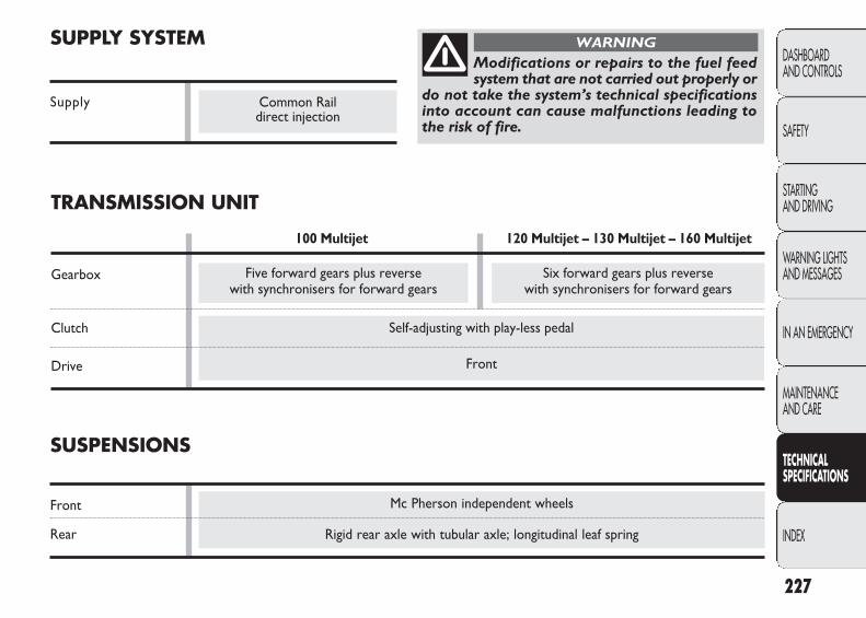
Mc Pherson independent wheels
Rigid rear axle with tubular axle; longitudinal leaf spring
Self-adjusting with play-less pedal
Front
SUPPLY SYSTEM
Supply system
227
DASHBOARD AND CONTROLS
SAFETY
STARTING AND DRIVING
WARNING LIGHTSAND MESSAGES
IN AN EMERGENCY
MAINTENANCE AND CARE
TECHNICAL SPECIFICATIONS
INDEX
Modifications or repairs to the fuel feedsystem that are not carried out properly or
do not take the system’s technical specificationsinto account can cause malfunctions leading tothe risk of fire.
WARNING
Five forward gears plus reverse with synchronisers for forward gears
Six forward gears plus reverse with synchronisers for forward gears
Common Rail direct injection
SUSPENSIONS
Front
Rear
TRANSMISSION UNIT
100 Multijet 120 Multijet – 130 Multijet – 160 Multijet
Gearbox
Clutch
Drive
223-276 DUCATO LUM EN 12-02-2010 13:09 Pagina 227
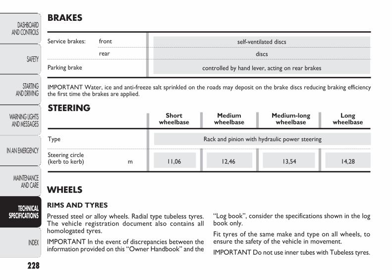
self-ventilated discs
discs
controlled by hand lever, acting on rear brakes
BRAKES
Service brakes: front
rear
Parking brake
IMPORTANT Water, ice and anti-freeze salt sprinkled on the roads may deposit on the brake discs reducing braking efficiencythe first time the brakes are applied.
WHEELS
RIMS AND TYRES
Pressed steel or alloy wheels. Radial type tubeless tyres.The vehicle registration document also contains all homologated tyres.
IMPORTANT In the event of discrepancies between theinformation provided on this “Owner Handbook” and the
“Log book”, consider the specifications shown in the logbook only.
Fit tyres of the same make and type on all wheels, toensure the safety of the vehicle in movement.
IMPORTANT Do not use inner tubes with Tubeless tyres.
228
DASHBOARD AND CONTROLS
SAFETY
STARTING AND DRIVING
WARNING LIGHTSAND MESSAGES
IN AN EMERGENCY
MAINTENANCE AND CARE
TECHNICAL SPECIFICATIONS
INDEX
STEERINGShort Medium Medium-long Long
wheelbase wheelbase wheelbase wheelbase
Type
Steering circle (kerb to kerb) m 11,06 12,46 13,54 14,28
Rack and pinion with hydraulic power steering
223-276 DUCATO LUM EN 12-02-2010 13:09 Pagina 228
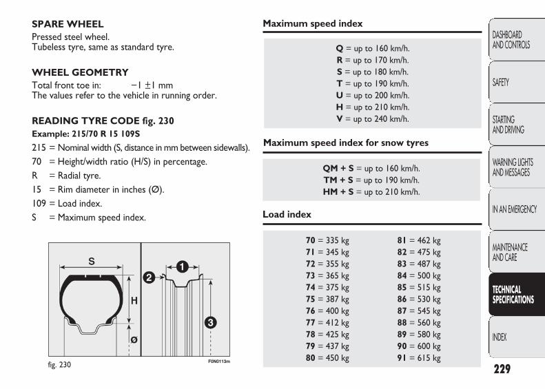
229
DASHBOARD AND CONTROLS
SAFETY
STARTING AND DRIVING
WARNING LIGHTSAND MESSAGES
IN AN EMERGENCY
MAINTENANCE AND CARE
TECHNICAL SPECIFICATIONS
INDEX
F0N0113mfig. 230
SPARE WHEELPressed steel wheel. Tubeless tyre, same as standard tyre.
WHEEL GEOMETRYTotal front toe in: −1 ±1 mmThe values refer to the vehicle in running order.
READING TYRE CODE fig. 230Example: 215/70 R 15 109S
215 = Nominal width (S, distance in mm between sidewalls).70 = Height/width ratio (H/S) in percentage.R = Radial tyre.15 = Rim diameter in inches (Ø).109 = Load index.S = Maximum speed index.
70 = 335 kg 81 = 462 kg 71 = 345 kg 82 = 475 kg 72 = 355 kg 83 = 487 kg 73 = 365 kg 84 = 500 kg 74 = 375 kg 85 = 515 kg 75 = 387 kg 86 = 530 kg 76 = 400 kg 87 = 545 kg 77 = 412 kg 88 = 560 kg 78 = 425 kg 89 = 580 kg 79 = 437 kg 90 = 600 kg 80 = 450 kg 91 = 615 kg
Q = up to 160 km/h.R = up to 170 km/h.S = up to 180 km/h.T = up to 190 km/h.U = up to 200 km/h.H = up to 210 km/h.V = up to 240 km/h.
QM + S = up to 160 km/h.TM + S = up to 190 km/h.HM + S = up to 210 km/h.
Maximum speed index
Maximum speed index for snow tyres
Load index
223-276 DUCATO LUM EN 12-02-2010 13:09 Pagina 229
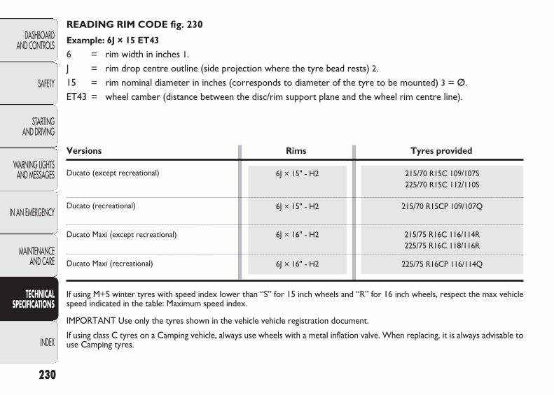
READING RIM CODE fig. 230
Example: 6J × 15 ET43
6 = rim width in inches 1.J = rim drop centre outline (side projection where the tyre bead rests) 2.15 = rim nominal diameter in inches (corresponds to diameter of the tyre to be mounted) 3 = Ø.ET43 = wheel camber (distance between the disc/rim support plane and the wheel rim centre line).
230
DASHBOARD AND CONTROLS
SAFETY
STARTING AND DRIVING
WARNING LIGHTSAND MESSAGES
IN AN EMERGENCY
MAINTENANCE AND CARE
TECHNICAL SPECIFICATIONS
INDEX
215/70 R15C 109/107S225/70 R15C 112/110S
215/70 R15CP 109/107Q
215/75 R16C 116/114R225/75 R16C 118/116R
225/75 R16CP 116/114Q
6J × 15" - H2
6J × 15" - H2
6J × 16" - H2
6J × 16" - H2
Versions Rims Tyres provided
Ducato (except recreational)
Ducato (recreational)
Ducato Maxi (except recreational)
Ducato Maxi (recreational)
If using M+S winter tyres with speed index lower than “S” for 15 inch wheels and “R” for 16 inch wheels, respect the max vehiclespeed indicated in the table: Maximum speed index.
IMPORTANT Use only the tyres shown in the vehicle vehicle registration document.
If using class C tyres on a Camping vehicle, always use wheels with a metal inflation valve. When replacing, it is always advisable touse Camping tyres.
223-276 DUCATO LUM EN 12-02-2010 13:09 Pagina 230
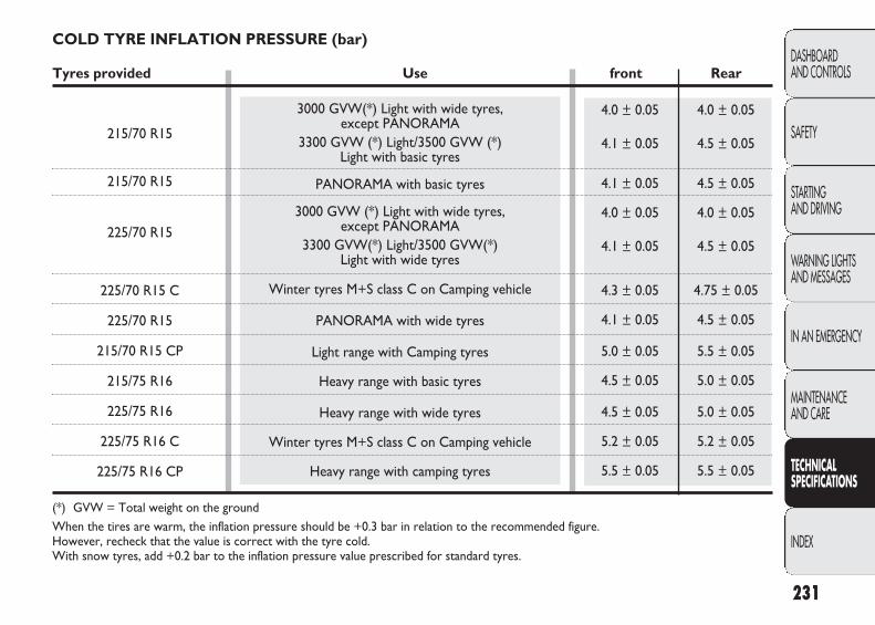
3000 GVW(*) Light with wide tyres, except PANORAMA
3300 GVW (*) Light/3500 GVW (*) Light with basic tyres
PANORAMA with basic tyres
3000 GVW (*) Light with wide tyres, except PANORAMA
3300 GVW(*) Light/3500 GVW(*) Light with wide tyres
Winter tyres M+S class C on Camping vehicle
PANORAMA with wide tyres
Light range with Camping tyres
Heavy range with basic tyres
Heavy range with wide tyres
Winter tyres M+S class C on Camping vehicle
Heavy range with camping tyres
4.0 ± 0.05 4.0 ± 0.05
4.1 ± 0.05 4.5 ± 0.05
4.1 ± 0.05 4.5 ± 0.05
4.0 ± 0.05 4.0 ± 0.05
4.1 ± 0.05 4.5 ± 0.05
4.3 ± 0.05 4.75 ± 0.05
4.1 ± 0.05 4.5 ± 0.05
5.0 ± 0.05 5.5 ± 0.05
4.5 ± 0.05 5.0 ± 0.05
4.5 ± 0.05 5.0 ± 0.05
5.2 ± 0.05 5.2 ± 0.05
5.5 ± 0.05 5.5 ± 0.05
COLD TYRE INFLATION PRESSURE (bar)
Tyres provided Use front Rear
215/70 R15
215/70 R15
225/70 R15
225/70 R15 C
225/70 R15
215/70 R15 CP
215/75 R16
225/75 R16
225/75 R16 C
225/75 R16 CP
(*) GVW = Total weight on the groundWhen the tires are warm, the inflation pressure should be +0.3 bar in relation to the recommended figure. However, recheck that the value is correct with the tyre cold. With snow tyres, add +0.2 bar to the inflation pressure value prescribed for standard tyres.
231
DASHBOARD AND CONTROLS
SAFETY
STARTING AND DRIVING
WARNING LIGHTSAND MESSAGES
IN AN EMERGENCY
MAINTENANCE AND CARE
TECHNICAL SPECIFICATIONS
INDEX
223-276 DUCATO LUM EN 12-02-2010 13:09 Pagina 231
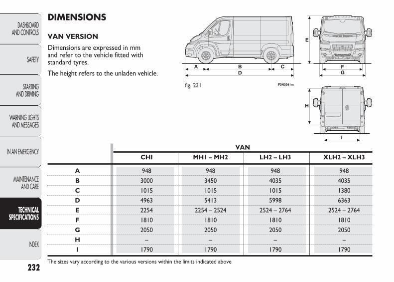
DIMENSIONS
VAN VERSION
Dimensions are expressed in mm and refer to the vehicle fitted withstandard tyres.
The height refers to the unladen vehicle.
232
DASHBOARD AND CONTROLS
SAFETY
STARTING AND DRIVING
WARNING LIGHTSAND MESSAGES
IN AN EMERGENCY
MAINTENANCE AND CARE
TECHNICAL SPECIFICATIONS
INDEX
fig. 231 F0N0341m
VAN
CHI MH1 – MH2 LH2 – LH3 XLH2 – XLH3
A 948 948 948 948
B 3000 3450 4035 4035
C 1015 1015 1015 1380
D 4963 5413 5998 6363
E 2254 2254 – 2524 2524 – 2764 2524 – 2764
F 1810 1810 1810 1810
G 2050 2050 2050 2050
H – – – –
I 1790 1790 1790 1790
The sizes vary according to the various versions within the limits indicated above
223-276 DUCATO LUM EN 12-02-2010 13:09 Pagina 232

233
DASHBOARD AND CONTROLS
SAFETY
STARTING AND DRIVING
WARNING LIGHTSAND MESSAGES
IN AN EMERGENCY
MAINTENANCE AND CARE
TECHNICAL SPECIFICATIONS
INDEX
BOX CHASSIS CAB
CHI MH1 LH1 XLH1 CHI MH1-MLH1 LH1 XLH1
A 948 948 948 948 948 948 948 948
B 3000 3450 4035 4035 3000 3450-3800 4035 4035
C 1345 1345 1345 1710 960 960 960 1325
D 5293 5743 6328 6693 4908 5358-5708 5943 6308
E 2798 3248 3833 4198 – – – –
F 2254 2254 2254 2254 2254 2254 2254 2254
G 1810 1810 1810 1810 1810 1810 1810 1810
H 1790 1790 1790 1790 1790÷1980 1790÷1980 1790÷1980 1790÷1980
L 2100 2100 2100 2100 2050 2050 2050 2050
The sizes vary according to the various versions within the limits indicated above
TRUCK VERSION
Dimensions are expressed in mm and refer to the vehicle fitted withstandard tyres.
The height refers to the unladen vehicle.
fig. 232 F0N0342m
223-276 DUCATO LUM EN 12-02-2010 13:09 Pagina 233

234
DASHBOARD AND CONTROLS
SAFETY
STARTING AND DRIVING
WARNING LIGHTSAND MESSAGES
IN AN EMERGENCY
MAINTENANCE AND CARE
TECHNICAL SPECIFICATIONS
INDEX
CHASSIS COWL SPECIAL CHASSIS CAB
CHI MH1-MLH1 LH1 XLH1 CHI MH1-MLH1 LH1 XLH1
A 925 925 925 925 948 948 948 948
B 3000 3450-3800 4035 4035 3000 3450-3800 4035 4035
C 860 860 860 1225 880 880 880 1245
D 4785 5235-5585 5820 6125 4828 5278-5628 5863 6228
E – – – – – – – –
F – – – – 2254 2254 2254 2254
G 1810 1810 1810 1810 1810 1810 1810 1810
H 1790÷1980 1790÷1980 1790÷1980 1790÷1980 1790÷1980 1790÷1980 1790÷1980 1790÷1980
L 2050 2050 2050 2050 2050 2050 2050 2050
The sizes vary according to the various versions within the limits indicated above
SPECIAL CHASSIS COWL
CHI MH1-MLH1 LH1 XLH1
A 925 925 925 925
B 3000 3450-3800 4035 4035
C 880 880 880 1245
D 4805 5255-5605 5840 6205
G 1810 1810 1810 1810
H 1790÷1980 1790÷1980 1790÷1980 1790÷1980
L 2050 2050 2050 2050
The sizes vary according to the various versions within the limits indicated above
223-276 DUCATO LUM EN 12-02-2010 13:09 Pagina 234

235
DASHBOARD AND CONTROLS
SAFETY
STARTING AND DRIVING
WARNING LIGHTSAND MESSAGES
IN AN EMERGENCY
MAINTENANCE AND CARE
TECHNICAL SPECIFICATIONS
INDEX
PERFORMANCES
Top admitted speed after initial vehicle use in km/h.
100 Multijet 120 Multijet 130 Multijet 160 Multijet
CH1-MH1 140 155 – 165
VAN MH2-LH2 135 150 – 160XLH2
LH3-XLH3 130 145 – 155
CH1 140 155 160 161(*) - 165 (▼)
TRUCKS MHI-MLHI 140 155 160 161(*) - 165 (▼)
LH1-XLH1 140 155 160 161(*) - 165 (▼)
(*) Heavy Range(▼) Light Range
223-276 DUCATO LUM EN 12-02-2010 13:09 Pagina 235

236
DASHBOARD AND CONTROLS
SAFETY
STARTING AND DRIVING
WARNING LIGHTSAND MESSAGES
IN AN EMERGENCY
MAINTENANCE AND CARE
TECHNICAL SPECIFICATIONS
INDEX
120 Multijet
1860÷1925
1075÷1140
163016503000
2500750
100
150
160 Multijet
1910÷1975
1025÷1090
163016503000
2500750
100
150
VAN WEIGHTS
3000 kg payload versions (***)
Unladen weight (with all fluids, fuel tank filled to 90% and without optional equipment): kg
Payload (*) including the driver: kg
Maximum permitted loads (**)– front axle: kg– rear axle: kg– total: kg
Towable loads– braked trailer: kg– non braked trailer: kg
Maximum load on the ball joint (braked trailer): kg
Maximum load on roof (evenly distributed): kg
(*) If special equipment is fitted (sunroof, tow hitch, etc.) the unladen vehicle weight increases, thus reducing the specifiedpayload.
(**) Loads not to be exceeded. The user is responsible for arranging goods in the luggage compartment and/on load carryingplatform within the maximum permitted loads.
(***) The values indicated refer to panel and glazed Vans and in medium and short wheelbases with high and low sides.
100 Multijet
1845÷1910
1090÷1155
163016503000
2000750
100
150
223-276 DUCATO LUM EN 12-02-2010 13:09 Pagina 236
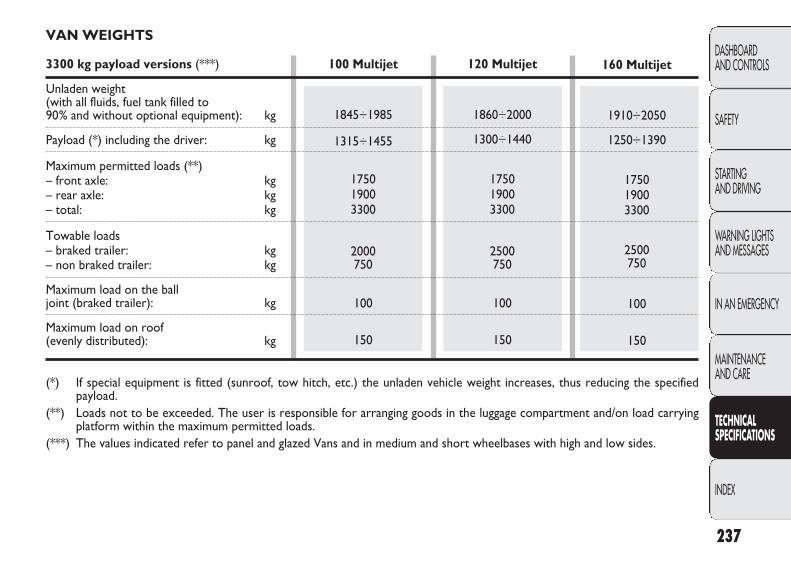
237
DASHBOARD AND CONTROLS
SAFETY
STARTING AND DRIVING
WARNING LIGHTSAND MESSAGES
IN AN EMERGENCY
MAINTENANCE AND CARE
TECHNICAL SPECIFICATIONS
INDEX
120 Multijet
1860÷2000
1300÷1440
175019003300
2500750
100
150
160 Multijet
1910÷2050
1250÷1390
175019003300
2500750
100
150
100 Multijet
1845÷1985
1315÷1455
175019003300
2000750
100
150
VAN WEIGHTS
3300 kg payload versions (***)
Unladen weight (with all fluids, fuel tank filled to 90% and without optional equipment): kg
Payload (*) including the driver: kg
Maximum permitted loads (**)– front axle: kg– rear axle: kg– total: kg
Towable loads– braked trailer: kg– non braked trailer: kg
Maximum load on the ball joint (braked trailer): kg
Maximum load on roof (evenly distributed): kg
(*) If special equipment is fitted (sunroof, tow hitch, etc.) the unladen vehicle weight increases, thus reducing the specifiedpayload.
(**) Loads not to be exceeded. The user is responsible for arranging goods in the luggage compartment and/on load carryingplatform within the maximum permitted loads.
(***) The values indicated refer to panel and glazed Vans and in medium and short wheelbases with high and low sides.
223-276 DUCATO LUM EN 12-02-2010 13:09 Pagina 237
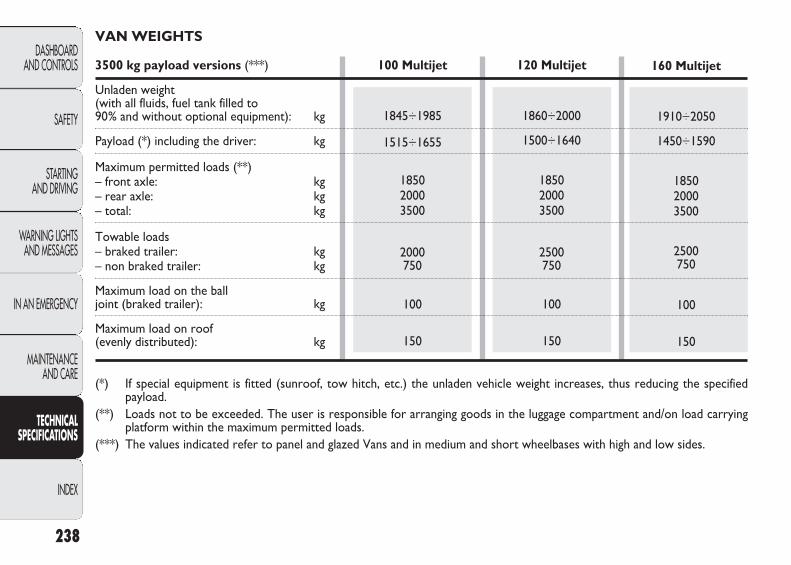
238
DASHBOARD AND CONTROLS
SAFETY
STARTING AND DRIVING
WARNING LIGHTSAND MESSAGES
IN AN EMERGENCY
MAINTENANCE AND CARE
TECHNICAL SPECIFICATIONS
INDEX
VAN WEIGHTS
3500 kg payload versions (***)
Unladen weight (with all fluids, fuel tank filled to 90% and without optional equipment): kg
Payload (*) including the driver: kg
Maximum permitted loads (**)– front axle: kg– rear axle: kg– total: kg
Towable loads– braked trailer: kg– non braked trailer: kg
Maximum load on the ball joint (braked trailer): kg
Maximum load on roof (evenly distributed): kg
(*) If special equipment is fitted (sunroof, tow hitch, etc.) the unladen vehicle weight increases, thus reducing the specifiedpayload.
(**) Loads not to be exceeded. The user is responsible for arranging goods in the luggage compartment and/on load carryingplatform within the maximum permitted loads.
(***) The values indicated refer to panel and glazed Vans and in medium and short wheelbases with high and low sides.
100 Multijet
1845÷1985
1515÷1655
185020003500
2000750
100
150
120 Multijet
1860÷2000
1500÷1640
185020003500
2500750
100
150
160 Multijet
1910÷2050
1450÷1590
185020003500
2500750
100
150
223-276 DUCATO LUM EN 12-02-2010 13:09 Pagina 238

239
DASHBOARD AND CONTROLS
SAFETY
STARTING AND DRIVING
WARNING LIGHTSAND MESSAGES
IN AN EMERGENCY
MAINTENANCE AND CARE
TECHNICAL SPECIFICATIONS
INDEX
120 Multijet
1940÷2090
1410÷1560
210024003500
3000750
120
150
160 Multijet
1990÷2140
1360÷1510
210024003500
3000750
120
150
VAN WEIGHTS (HEAVY versions)
3500 kg payload versions (***)
Unladen weight (with all fluids, fuel tank filled to 90% and without optional equipment): kg
Payload (*) including the driver: kg
Maximum permitted loads (**)– front axle: kg– rear axle: kg– total: kg
Towable loads– braked trailer: kg– non braked trailer: kg
Maximum load on the ball joint (braked trailer): kg
Maximum load on roof (evenly distributed): kg
(*) If special equipment is fitted (sunroof, tow hitch, etc.) the unladen vehicle weight increases, thus reducing the specifiedpayload.
(**) Loads not to be exceeded. The user is responsible for arranging goods in the luggage compartment and/on load carryingplatform within the maximum permitted loads.
(***) The values indicated refer to panel and glazed Vans and in medium and short wheelbases with high and low sides.
223-276 DUCATO LUM EN 12-02-2010 13:09 Pagina 239

240
DASHBOARD AND CONTROLS
SAFETY
STARTING AND DRIVING
WARNING LIGHTSAND MESSAGES
IN AN EMERGENCY
MAINTENANCE AND CARE
TECHNICAL SPECIFICATIONS
INDEX
VAN WEIGHTS (HEAVY versions)
4000 kg payload versions (***)
Unladen weight (with all fluids, fuel tank filled to 90% and without optional equipment): kg
Payload (*) including the driver: kg
Maximum permitted loads (**) – front axle: kg– rear axle: kg– total: kg
Towable loads – braked trailer: kg– non braked trailer: kg
Maximum load on the ball joint (braked trailer): kg
Maximum load on roof (evenly distributed): kg
(*) If special equipment is fitted (sunroof, tow hitch, etc.) the unladen vehicle weight increases, thus reducing the specifiedpayload.
(**) Loads not to be exceeded. The user is responsible for arranging goods in the luggage compartment and/on load carryingplatform within the maximum permitted loads.
(***) The values indicated refer to panel and glazed Vans and in medium and short wheelbases with high and low sides.
120 Multijet
2010÷2135
1865÷1990
210024004000
2500750
100
150
160 Multijet
2060÷2185
1815÷1940
210024004000
2500750
100
150
223-276 DUCATO LUM EN 12-02-2010 13:09 Pagina 240
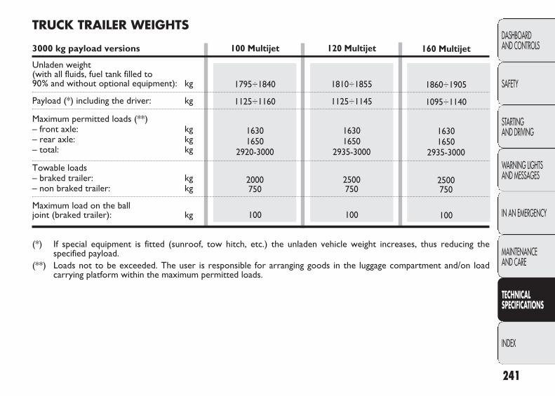
241
DASHBOARD AND CONTROLS
SAFETY
STARTING AND DRIVING
WARNING LIGHTSAND MESSAGES
IN AN EMERGENCY
MAINTENANCE AND CARE
TECHNICAL SPECIFICATIONS
INDEX
120 Multijet
1810÷1855
1125÷1145
16301650
2935-3000
2500750
100
160 Multijet
1860÷1905
1095÷1140
16301650
2935-3000
2500750
100
TRUCK TRAILER WEIGHTS
3000 kg payload versions
Unladen weight (with all fluids, fuel tank filled to 90% and without optional equipment): kg
Payload (*) including the driver: kg
Maximum permitted loads (**)– front axle: kg– rear axle: kg– total: kg
Towable loads– braked trailer: kg– non braked trailer: kg
Maximum load on the ball joint (braked trailer): kg
(*) If special equipment is fitted (sunroof, tow hitch, etc.) the unladen vehicle weight increases, thus reducing thespecified payload.
(**) Loads not to be exceeded. The user is responsible for arranging goods in the luggage compartment and/on loadcarrying platform within the maximum permitted loads.
100 Multijet
1795÷1840
1125÷1160
16301650
2920-3000
2000750
100
223-276 DUCATO LUM EN 12-02-2010 13:09 Pagina 241

242
DASHBOARD AND CONTROLS
SAFETY
STARTING AND DRIVING
WARNING LIGHTSAND MESSAGES
IN AN EMERGENCY
MAINTENANCE AND CARE
TECHNICAL SPECIFICATIONS
INDEX
120 Multijet
1810÷1910
1390÷1435
17501900
3245-3300
2500750
100
160 Multijet
1860÷1960
1340÷1440
17501900
3245-3300
2500750
100
100 Multijet
1795÷1895
1405÷1435
17501900
3230-3300
2000750
100
TRUCK TRAILER WEIGHTS
3300 kg payload versions
Unladen weight (with all fluids, fuel tank filled to 90% and without optional equipment): kg
Payload (*) including the driver: kg
Maximum permitted loads (**)– front axle: kg– rear axle: kg– total: kg
Towable loads– braked trailer: kg– non braked trailer: kg
Maximum load on the ball joint (braked trailer): kg
(*) If special equipment is fitted (sunroof, tow hitch, etc.) the unladen vehicle weight increases, thus reducing the specifiedpayload.
(**) Loads not to be exceeded. The user is responsible for arranging goods in the luggage compartment and/on load carryingplatform within the maximum permitted loads.
223-276 DUCATO LUM EN 12-02-2010 13:09 Pagina 242
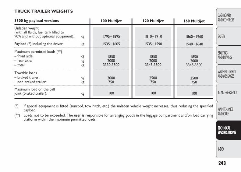
243
DASHBOARD AND CONTROLS
SAFETY
STARTING AND DRIVING
WARNING LIGHTSAND MESSAGES
IN AN EMERGENCY
MAINTENANCE AND CARE
TECHNICAL SPECIFICATIONS
INDEX
120 Multijet
1810÷1910
1535÷1590
18502000
3345-3500
2500750
100
160 Multijet
1860÷1960
1540÷1640
18502000
3345-3500
2500750
100
100 Multijet
1795÷1895
1535÷1605
18502000
3330-3500
2000750
100
TRUCK TRAILER WEIGHTS
3500 kg payload versions
Unladen weight (with all fluids, fuel tank filled to 90% and without optional equipment): kg
Payload (*) including the driver: kg
Maximum permitted loads (**)– front axle: kg– rear axle: kg– total: kg
Towable loads– braked trailer: kg– non braked trailer: kg
Maximum load on the ball joint (braked trailer): kg
(*) If special equipment is fitted (sunroof, tow hitch, etc.) the unladen vehicle weight increases, thus reducing the specifiedpayload.
(**) Loads not to be exceeded. The user is responsible for arranging goods in the luggage compartment and/on load carryingplatform within the maximum permitted loads.
223-276 DUCATO LUM EN 12-02-2010 13:09 Pagina 243

244
DASHBOARD AND CONTROLS
SAFETY
STARTING AND DRIVING
WARNING LIGHTSAND MESSAGES
IN AN EMERGENCY
MAINTENANCE AND CARE
TECHNICAL SPECIFICATIONS
INDEX
120 Multijet
1895÷1985
1515÷1605
210024003500
2500750
120
160 Multijet
1945÷2035
1465÷1555
210024003500
2500750
120
TRAILER TRUCK WEIGHTS (HEAVY versions)
3500 kg payload versions
Unladen weight (with all fluids, fuel tank filled to 90% and without optional equipment): kg
Payload (*) including the driver: kg
Maximum permitted loads (**)– front axle: kg– rear axle: kg– total: kg
Towable loads– braked trailer: kg– non braked trailer: kg
Maximum load on the ball joint (braked trailer): kg
(*) If special equipment is fitted (sunroof, tow hitch, etc.) the unladen vehicle weight increases, thus reducing the specifiedpayload.
(**) Loads not to be exceeded. The user is responsible for arranging goods in the luggage compartment and/on load carryingplatform within the maximum permitted loads.
223-276 DUCATO LUM EN 12-02-2010 13:09 Pagina 244

245
DASHBOARD AND CONTROLS
SAFETY
STARTING AND DRIVING
WARNING LIGHTSAND MESSAGES
IN AN EMERGENCY
MAINTENANCE AND CARE
TECHNICAL SPECIFICATIONS
INDEX
120 Multijet
1895÷1985
2015÷2105
210024004000
2500750
100
160 Multijet
1945÷2035
1965÷2055
210024004000
2500750
100
TRAILER TRUCK WEIGHTS (HEAVY versions)
4000 kg payload versions
Unladen weight (with all fluids, fuel tank filled to 90% and without optional equipment): kg
Payload (*) including the driver: kg
Maximum permitted loads (**)– front axle: kg– rear axle: kg– total: kg
Towable loads– braked trailer: kg– non braked trailer: kg
Maximum load on the ball joint (braked trailer): kg
(*) If special equipment is fitted (sunroof, tow hitch, etc.) the unladen vehicle weight increases, thus reducing the specifiedpayload.
(**) Loads not to be exceeded. The user is responsible for arranging goods in the luggage compartment and/on load carryingplatform within the maximum permitted loads.
223-276 DUCATO LUM EN 12-02-2010 13:09 Pagina 245

246
DASHBOARD AND CONTROLS
SAFETY
STARTING AND DRIVING
WARNING LIGHTSAND MESSAGES
IN AN EMERGENCY
MAINTENANCE AND CARE
TECHNICAL SPECIFICATIONS
INDEX
100 Multijet
1600
163016503000
2000750
100
120 Multijet
1615
163016503000
2500750
100
WEIGHTS OF CHASSIS CAB FRAME WITH PLATFORM
3000 kg payload versions
Unladen weight (with all fluids, fuel tank filled to 90% and without optional equipment): kg
Maximum permitted loads (**)– front axle: kg– rear axle: kg– total: kg
Towable loads– braked trailer: kg– non braked trailer: kg
Maximum load on the ball joint (braked trailer): kg
If special equipment is fitted (sunroof, tow hitch, etc.) the unladen vehicle weight increases, thus reducing the specifiedpayload.(**) Loads not to be exceeded. The user is responsible for arranging goods in the luggage compartment and/on load carrying
platform within the maximum permitted loads.
223-276 DUCATO LUM EN 12-02-2010 13:09 Pagina 246

247
DASHBOARD AND CONTROLS
SAFETY
STARTING AND DRIVING
WARNING LIGHTSAND MESSAGES
IN AN EMERGENCY
MAINTENANCE AND CARE
TECHNICAL SPECIFICATIONS
INDEX
100 Multijet
1580÷1615
175019003300
2000750
100
120 Multijet
1595÷1630
175019003300
2500750
100
WEIGHTS OF CHASSIS CAB FRAME WITH PLATFORM
3300 kg payload versions
Unladen weight (with all fluids, fuel tank filled to 90% and without optional equipment): kg
Maximum permitted loads (**)– front axle: kg– rear axle: kg– total: kg
Towable loads– braked trailer: kg– non braked trailer: kg
Maximum load on the ball joint (braked trailer): kg
If special equipment is fitted (sunroof, tow hitch, etc.) the unladen vehicle weight increases, thus reducing the specifiedpayload.(**) Loads not to be exceeded. The driver is responsible for arranging goods in the luggage compartment and/on load
carrying platform within the maximum permitted loads.
223-276 DUCATO LUM EN 12-02-2010 13:09 Pagina 247

248
DASHBOARD AND CONTROLS
SAFETY
STARTING AND DRIVING
WARNING LIGHTSAND MESSAGES
IN AN EMERGENCY
MAINTENANCE AND CARE
TECHNICAL SPECIFICATIONS
INDEX
100 Multijet
1580÷1615
185020003500
2000750
100
120 Multijet
1595÷1630
185020003500
2500750
100
WEIGHTS OF CHASSIS CAB FRAME WITH PLATFORM
3500 kg payload versions
Unladen weight (with all fluids, fuel tank filled to 90% and without optional equipment): kg
Maximum permitted loads (**)– front axle: kg– rear axle: kg– total: kg
Towable loads– braked trailer: kg– non braked trailer: kg
Maximum load on the ball joint (braked trailer): kg
If special equipment is fitted (sunroof, tow hitch, etc.) the unladen vehicle weight increases, thus reducing the specifiedpayload.(**) Loads not to be exceeded. The driver is responsible for arranging goods in the luggage compartment and/on load
carrying platform within the maximum permitted loads.
223-276 DUCATO LUM EN 12-02-2010 13:09 Pagina 248
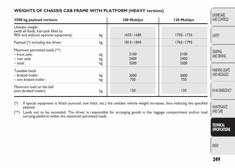
249
DASHBOARD AND CONTROLS
SAFETY
STARTING AND DRIVING
WARNING LIGHTSAND MESSAGES
IN AN EMERGENCY
MAINTENANCE AND CARE
TECHNICAL SPECIFICATIONS
INDEX
100 Multijet
1655÷1685
1815÷1845
210024003500
3000750
120
120 Multijet
1705÷1735
1765÷1795
210024003500
3000750
120
WEIGHTS OF CHASSIS CAB FRAME WITH PLATFORM (HEAVY versions)
3500 kg payload versions
Unladen weight (with all fluids, fuel tank filled to 90% and without optional equipment): kg
Payload (*) including the driver: kg
Maximum permitted loads (**)– front axle: kg– rear axle: kg– total: kg
Towable loads– braked trailer: kg– non braked trailer: kg
Maximum load on the ball joint (braked trailer): kg
(*) If special equipment is fitted (sunroof, tow hitch, etc.) the unladen vehicle weight increases, thus reducing the specifiedpayload.
(**) Loads not to be exceeded. The driver is responsible for arranging goods in the luggage compartment and/on loadcarrying platform within the maximum permitted loads.
223-276 DUCATO LUM EN 12-02-2010 13:09 Pagina 249
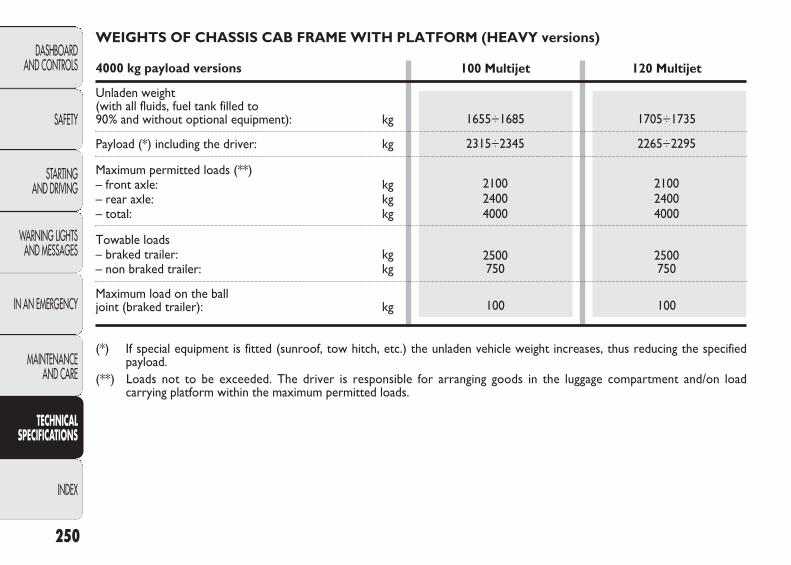
250
DASHBOARD AND CONTROLS
SAFETY
STARTING AND DRIVING
WARNING LIGHTSAND MESSAGES
IN AN EMERGENCY
MAINTENANCE AND CARE
TECHNICAL SPECIFICATIONS
INDEX
100 Multijet
1655÷1685
2315÷2345
210024004000
2500750
100
120 Multijet
1705÷1735
2265÷2295
210024004000
2500750
100
WEIGHTS OF CHASSIS CAB FRAME WITH PLATFORM (HEAVY versions)
4000 kg payload versions
Unladen weight (with all fluids, fuel tank filled to 90% and without optional equipment): kg
Payload (*) including the driver: kg
Maximum permitted loads (**)– front axle: kg– rear axle: kg– total: kg
Towable loads– braked trailer: kg– non braked trailer: kg
Maximum load on the ball joint (braked trailer): kg
(*) If special equipment is fitted (sunroof, tow hitch, etc.) the unladen vehicle weight increases, thus reducing the specifiedpayload.
(**) Loads not to be exceeded. The driver is responsible for arranging goods in the luggage compartment and/on loadcarrying platform within the maximum permitted loads.
223-276 DUCATO LUM EN 12-02-2010 13:09 Pagina 250
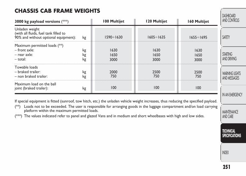
251
DASHBOARD AND CONTROLS
SAFETY
STARTING AND DRIVING
WARNING LIGHTSAND MESSAGES
IN AN EMERGENCY
MAINTENANCE AND CARE
TECHNICAL SPECIFICATIONS
INDEX
120 Multijet
1605÷1635
163016503000
2500750
100
160 Multijet
1655÷1695
163016503000
2500750
100
CHASSIS CAB FRAME WEIGHTS
3000 kg payload versions (***)
Unladen weight (with all fluids, fuel tank filled to 90% and without optional equipment): kg
Maximum permitted loads (**)– front axle: kg– rear axle: kg– total: kg
Towable loads– braked trailer: kg– non braked trailer: kg
Maximum load on the ball joint (braked trailer): kg
If special equipment is fitted (sunroof, tow hitch, etc.) the unladen vehicle weight increases, thus reducing the specified payload.(**) Loads not to be exceeded. The user is responsible for arranging goods in the luggage compartment and/on load carrying
platform within the maximum permitted loads.(***) The values indicated refer to panel and glazed Vans and in medium and short wheelbases with high and low sides.
100 Multijet
1590÷1630
163016503000
2000750
100
223-276 DUCATO LUM EN 12-02-2010 13:09 Pagina 251
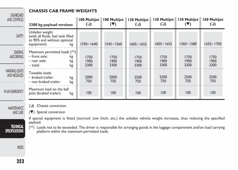
120 Multijet(❏)
1605÷1655
175019003300
2500750
100
100 Multijet(▼)
1545÷1560
175019003300
2000750
100
100 Multijet(❏)
1590÷1640
175019003300
2000750
100
130 Multijet(❏)
1605÷1655
175019003300
2500750
100
130 Multijet(▼)
1560÷1580
175019003300
2500750
100
160 Multijet(❏)
1655÷1705
175019003300
2500750
100
252
DASHBOARD AND CONTROLS
SAFETY
STARTING AND DRIVING
WARNING LIGHTSAND MESSAGES
IN AN EMERGENCY
MAINTENANCE AND CARE
TECHNICAL SPECIFICATIONS
INDEX
CHASSIS CAB FRAME WEIGHTS
3300 kg payload versions
Unladen weight (with all fluids, fuel tank filled to 90% and without optional equipment): kg
Maximum permitted loads (**)– front axle: kg– rear axle: kg– total: kg
Towable loads– braked trailer: kg– non braked trailer: kg
Maximum load on the ball joint (braked trailer): kg
(❏) Chassis conversion
(▼) Special conversion
If special equipment is fitted (sunroof, tow hitch, etc.) the unladen vehicle weight increases, thus reducing the specifiedpayload.(**) Loads not to be exceeded. The driver is responsible for arranging goods in the luggage compartment and/on load carrying
platform within the maximum permitted loads.
223-276 DUCATO LUM EN 12-02-2010 13:09 Pagina 252
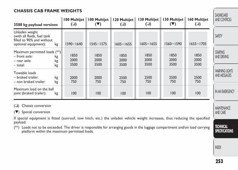
253
DASHBOARD AND CONTROLS
SAFETY
STARTING AND DRIVING
WARNING LIGHTSAND MESSAGES
IN AN EMERGENCY
MAINTENANCE AND CARE
TECHNICAL SPECIFICATIONS
INDEX
120 Multijet(❏)
1605÷1655
185020003500
2500750
100
100 Multijet(▼)
1545÷1575
185020003500
2000750
100
100 Multijet(❏)
1590÷1640
185020003500
2000750
100
130 Multijet(❏)
1605÷1655
185020003500
2500750
100
130 Multijet(▼)
1560÷1590
185020003500
2500750
100
160 Multijet(❏)
1655÷1705
185020003500
2500750
100
CHASSIS CAB FRAME WEIGHTS
3500 kg payload versions
Unladen weight (with all fluids, fuel tank filled to 90% and without optional equipment): kg
Maximum permitted loads (**)– front axle: kg– rear axle: kg– total: kg
Towable loads– braked trailer: kg– non braked trailer: kg
Maximum load on the ball joint (braked trailer): kg
(❏) Chassis conversion
(▼) Special conversion
If special equipment is fitted (sunroof, tow hitch, etc.) the unladen vehicle weight increases, thus reducing the specifiedpayload.(**) Loads not to be exceeded. The driver is responsible for arranging goods in the luggage compartment and/on load carrying
platform within the maximum permitted loads.
223-276 DUCATO LUM EN 12-02-2010 13:09 Pagina 253
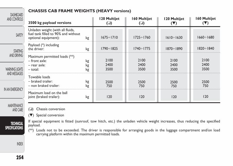
254
DASHBOARD AND CONTROLS
SAFETY
STARTING AND DRIVING
WARNING LIGHTSAND MESSAGES
IN AN EMERGENCY
MAINTENANCE AND CARE
TECHNICAL SPECIFICATIONS
INDEX
120 Multijet(❏)
1675÷1710
1790÷1825
210024003500
2500750
120
160 Multijet(❏)
1725÷1760
1740÷1775
210024003500
2500750
120
120 Multijet(▼)
1610÷1630
1870÷1890
210024003500
2500750
120
160 Multijet(▼)
1660÷1680
1820÷1840
210024003500
2500750
120
CHASSIS CAB FRAME WEIGHTS (HEAVY versions)
3500 kg payload versions
Unladen weight (with all fluids, fuel tank filled to 90% and without optional equipment): kg
Payload (*) including the driver: kg
Maximum permitted loads (**)– front axle: kg– rear axle: kg– total: kg
Towable loads– braked trailer: kg– non braked trailer: kg
Maximum load on the ball joint (braked trailer): kg
(❏) Chassis conversion
(▼) Special conversion
If special equipment is fitted (sunroof, tow hitch, etc.) the unladen vehicle weight increases, thus reducing the specifiedpayload.(**) Loads not to be exceeded. The driver is responsible for arranging goods in the luggage compartment and/on load
carrying platform within the maximum permitted loads.
223-276 DUCATO LUM EN 12-02-2010 13:10 Pagina 254

255
DASHBOARD AND CONTROLS
SAFETY
STARTING AND DRIVING
WARNING LIGHTSAND MESSAGES
IN AN EMERGENCY
MAINTENANCE AND CARE
TECHNICAL SPECIFICATIONS
INDEX
120 Multijet(❏)
1675÷1710
2290÷2325
210024004000
2500750
100
160 Multijet(❏)
1725÷1760
2240÷2275
210024004000
2500750
100
120 Multijet(▼)
1610÷1630
2370÷2390
210024004000
2500750
100
160 Multijet(▼)
1660÷1680
2320÷2340
210024004000
2500750
100
CHASSIS CAB FRAME WEIGHTS (HEAVY versions)
4000 kg payload versions
Unladen weight (with all fluids, fuel tank filled to 90% and without optional equipment): kg
Payload (*) including the driver: kg
Maximum permitted loads (**)– front axle: kg– rear axle: kg– total: kg
Towable loads– braked trailer: kg– non braked trailer: kg
Maximum load on the ball joint (braked trailer): kg
(❏) Chassis conversion
(▼) Special conversion
If special equipment is fitted (sunroof, tow hitch, etc.) the unladen vehicle weight increases, thus reducing the specifiedpayload.(**) Loads not to be exceeded. The driver is responsible for arranging goods in the luggage compartment and/on load
carrying platform within the maximum permitted loads.
223-276 DUCATO LUM EN 12-02-2010 13:10 Pagina 255

256
DASHBOARD AND CONTROLS
SAFETY
STARTING AND DRIVING
WARNING LIGHTSAND MESSAGES
IN AN EMERGENCY
MAINTENANCE AND CARE
TECHNICAL SPECIFICATIONS
INDEX
120 Multijet(❏)
1375÷1410
2090÷2125
210024003500
2500750
120
160 Multijet(❏)
1425÷1460
2040÷2075
210024003500
2500750
120
120 Multijet(▼)
1310÷1330
2170÷2190
210024003500
2500750
120
160 Multijet(▼)
1360÷1380
2120÷2140
210024003500
2500750
120
CHASSIS COWL WEIGHTS (HEAVY versions)
3500 kg payload versions
Unladen weight (with all fluids, fuel tank filled to 90% and without optional equipment): kg
Payload (*) including the driver: kg
Maximum permitted loads (**)– front axle: kg– rear axle: kg– total: kg
Towable loads– braked trailer: kg– non braked trailer: kg
Maximum load on the ball joint (braked trailer): kg
(❏) Chassis conversion
(▼) Special conversion
(*) If special equipment is fitted (sunroof, tow hitch, etc.) the unladen vehicle weight increases, thus reducing the specifiedpayload.
(**) Loads not to be exceeded. The driver is responsible for arranging goods in the luggage compartment and/on loadcarrying platform within the maximum permitted loads.
223-276 DUCATO LUM EN 12-02-2010 13:10 Pagina 256
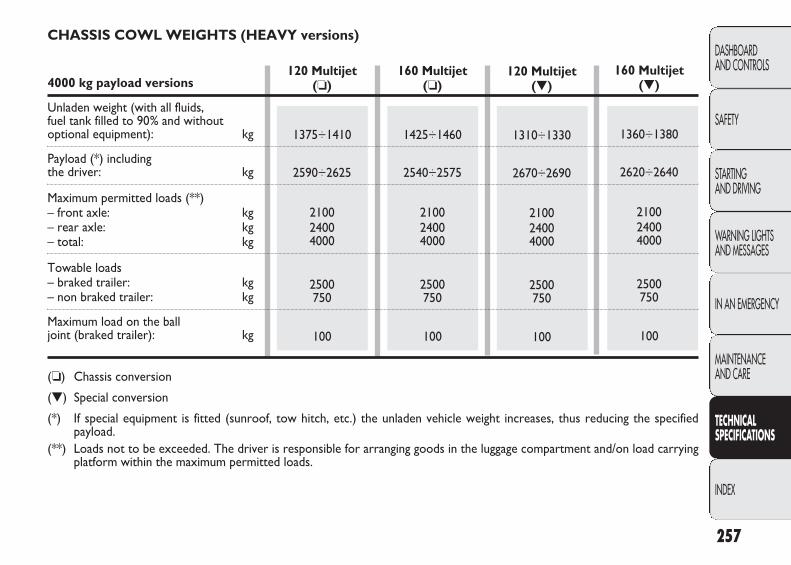
257
DASHBOARD AND CONTROLS
SAFETY
STARTING AND DRIVING
WARNING LIGHTSAND MESSAGES
IN AN EMERGENCY
MAINTENANCE AND CARE
TECHNICAL SPECIFICATIONS
INDEX
120 Multijet(❏)
1375÷1410
2590÷2625
210024004000
2500750
100
160 Multijet(❏)
1425÷1460
2540÷2575
210024004000
2500750
100
120 Multijet(▼)
1310÷1330
2670÷2690
210024004000
2500750
100
160 Multijet(▼)
1360÷1380
2620÷2640
210024004000
2500750
100
CHASSIS COWL WEIGHTS (HEAVY versions)
4000 kg payload versions
Unladen weight (with all fluids, fuel tank filled to 90% and without optional equipment): kg
Payload (*) including the driver: kg
Maximum permitted loads (**)– front axle: kg– rear axle: kg– total: kg
Towable loads– braked trailer: kg– non braked trailer: kg
Maximum load on the ball joint (braked trailer): kg
(❏) Chassis conversion
(▼) Special conversion
(*) If special equipment is fitted (sunroof, tow hitch, etc.) the unladen vehicle weight increases, thus reducing the specifiedpayload.
(**) Loads not to be exceeded. The driver is responsible for arranging goods in the luggage compartment and/on load carryingplatform within the maximum permitted loads.
223-276 DUCATO LUM EN 12-02-2010 13:10 Pagina 257

258
DASHBOARD AND CONTROLS
SAFETY
STARTING AND DRIVING
WARNING LIGHTSAND MESSAGES
IN AN EMERGENCY
MAINTENANCE AND CARE
TECHNICAL SPECIFICATIONS
INDEX
120 Multijet
1965÷2025
1275÷1335
175019003300
2500750
100
160 Multijet
2015÷2075
1225÷1285
175019003300
2500750
100
CREW CAB WEIGHTS
3300 kg payload versions
Unladen weight (with all fluids, fuel tank filled to 90% and without optional equipment): kg
Payload (*) including the driver: kg
Maximum permitted loads (**)– front axle: kg– rear axle: kg– total: kg
Towable loads– braked trailer: kg– non braked trailer: kg
Maximum load on the ball joint (braked trailer): kg
(*) If special equipment is fitted (sunroof, tow hitch, etc.) the unladen vehicle weight increases, thus reducing the specifiedpayload.
(**) Loads not to be exceeded. The driver is responsible for arranging goods in the luggage compartment and/on loadcarrying platform within the maximum permitted loads.
100 Multijet
1950÷2010
1290÷1350
175019003300
2000750
100
223-276 DUCATO LUM EN 12-02-2010 13:10 Pagina 258

259
DASHBOARD AND CONTROLS
SAFETY
STARTING AND DRIVING
WARNING LIGHTSAND MESSAGES
IN AN EMERGENCY
MAINTENANCE AND CARE
TECHNICAL SPECIFICATIONS
INDEX
120 Multijet
1965÷2025
1475÷1535
210024003500
2500750
120
160 Multijet
2015÷2075
1425÷1485
210024003500
2500750
120
100 Multijet
1950÷2010
1490÷1550
210024003500
2500750
120
CREW CAB WEIGHTS
3500 kg payload versions
Unladen weight (with all fluids, fuel tank filled to 90% and without optional equipment): kg
Payload (*) including the driver: kg
Maximum permitted loads (**)– front axle: kg– rear axle: kg– total: kg
Towable loads– braked trailer: kg– non braked trailer: kg
Maximum load on the ball joint (braked trailer): kg
(*) If special equipment is fitted (sunroof, tow hitch, etc.) the unladen vehicle weight increases, thus reducing the specifiedpayload.
(**) Loads not to be exceeded. The driver is responsible for arranging goods in the luggage compartment and/on loadcarrying platform within the maximum permitted loads.
223-276 DUCATO LUM EN 12-02-2010 13:10 Pagina 259

260
DASHBOARD AND CONTROLS
SAFETY
STARTING AND DRIVING
WARNING LIGHTSAND MESSAGES
IN AN EMERGENCY
MAINTENANCE AND CARE
TECHNICAL SPECIFICATIONS
INDEX
120 Multijet
2005÷2105
1395÷1495
210024003500
2500750
120
160 Multijet
2055÷2155
1345÷1445
210024003500
2500750
120
CREW CAB WEIGHTS (HEAVY versions)
3500 kg payload versions
Unladen weight (with all fluids, fuel tank filled to 90% and without optional equipment): kg
Payload (*) including the driver: kg
Maximum permitted loads (**)– front axle: kg– rear axle: kg– total: kg
Towable loads– braked trailer: kg– non braked trailer: kg
Maximum load on the ball joint (braked trailer): kg
(*) If special equipment is fitted (sunroof, tow hitch, etc.) the unladen vehicle weight increases, thus reducing the specifiedpayload.
(**) Loads not to be exceeded. The user is responsible for arranging goods in the luggage compartment and/on load carryingplatform within the maximum permitted loads.
223-276 DUCATO LUM EN 12-02-2010 13:10 Pagina 260

261
DASHBOARD AND CONTROLS
SAFETY
STARTING AND DRIVING
WARNING LIGHTSAND MESSAGES
IN AN EMERGENCY
MAINTENANCE AND CARE
TECHNICAL SPECIFICATIONS
INDEX
120 Multijet
1950
1050
160016503000
2500750
100
160 Multijet
2000
1000
160016503000
2500750
100
100 Multijet
1935
1065
160016503000
2000750
100
COMBI WEIGHTS
3000 kg payload versions
Unladen weight (with all fluids, fuel tank filled to 90% and without optional equipment): kg
Payload (*) including the driver: kg
Maximum permitted loads (**)– front axle: kg– rear axle: kg– total: kg
Towable loads– braked trailer: kg– non braked trailer: kg
Maximum load on the ball joint (braked trailer): kg
(*) If special equipment is fitted (sunroof, tow hitch, etc.) the unladen vehicle weight increases, thus reducing the specifiedpayload.
(**) Loads not to be exceeded. The driver is responsible for arranging goods in the luggage compartment and/on loadcarrying platform within the maximum permitted loads.
223-276 DUCATO LUM EN 12-02-2010 13:10 Pagina 261
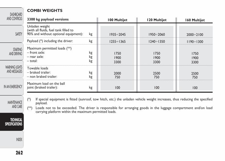
262
DASHBOARD AND CONTROLS
SAFETY
STARTING AND DRIVING
WARNING LIGHTSAND MESSAGES
IN AN EMERGENCY
MAINTENANCE AND CARE
TECHNICAL SPECIFICATIONS
INDEX
120 Multijet
1950÷2060
1240÷1350
175019003300
2500750
100
160 Multijet
2000÷2100
1190÷1300
175019003300
2500750
100
COMBI WEIGHTS
3300 kg payload versions
Unladen weight (with all fluids, fuel tank filled to 90% and without optional equipment): kg
Payload (*) including the driver: kg
Maximum permitted loads (**)– front axle: kg– rear axle: kg– total: kg
Towable loads– braked trailer: kg– non braked trailer: kg
Maximum load on the ball joint (braked trailer): kg
(*) If special equipment is fitted (sunroof, tow hitch, etc.) the unladen vehicle weight increases, thus reducing the specifiedpayload.
(**) Loads not to be exceeded. The driver is responsible for arranging goods in the luggage compartment and/on loadcarrying platform within the maximum permitted loads.
100 Multijet
1935÷2045
1255÷1365
175019003300
2000750
100
223-276 DUCATO LUM EN 12-02-2010 13:10 Pagina 262
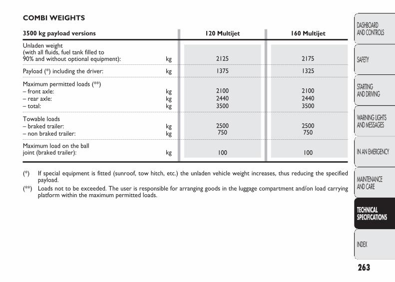
263
DASHBOARD AND CONTROLS
SAFETY
STARTING AND DRIVING
WARNING LIGHTSAND MESSAGES
IN AN EMERGENCY
MAINTENANCE AND CARE
TECHNICAL SPECIFICATIONS
INDEX
COMBI WEIGHTS
3500 kg payload versions
Unladen weight (with all fluids, fuel tank filled to 90% and without optional equipment): kg
Payload (*) including the driver: kg
Maximum permitted loads (**)– front axle: kg– rear axle: kg– total: kg
Towable loads– braked trailer: kg– non braked trailer: kg
Maximum load on the ball joint (braked trailer): kg
(*) If special equipment is fitted (sunroof, tow hitch, etc.) the unladen vehicle weight increases, thus reducing the specifiedpayload.
(**) Loads not to be exceeded. The user is responsible for arranging goods in the luggage compartment and/on load carryingplatform within the maximum permitted loads.
120 Multijet
2125
1375
210024403500
2500750
100
160 Multijet
2175
1325
210024403500
2500750
100
223-276 DUCATO LUM EN 12-02-2010 13:10 Pagina 263
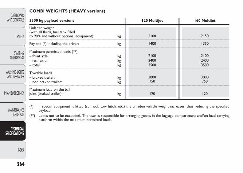
264
DASHBOARD AND CONTROLS
SAFETY
STARTING AND DRIVING
WARNING LIGHTSAND MESSAGES
IN AN EMERGENCY
MAINTENANCE AND CARE
TECHNICAL SPECIFICATIONS
INDEX
COMBI WEIGHTS (HEAVY versions)
3500 kg payload versions
Unladen weight (with all fluids, fuel tank filled to 90% and without optional equipment): kg
Payload (*) including the driver: kg
Maximum permitted loads (**)– front axle: kg– rear axle: kg– total: kg
Towable loads– braked trailer: kg– non braked trailer: kg
Maximum load on the ball joint (braked trailer): kg
(*) If special equipment is fitted (sunroof, tow hitch, etc.) the unladen vehicle weight increases, thus reducing the specifiedpayload.
(**) Loads not to be exceeded. The user is responsible for arranging goods in the luggage compartment and/on load carryingplatform within the maximum permitted loads.
120 Multijet
2100
1400
210024003500
3000750
120
160 Multijet
2150
1350
210024003500
3000750
120
223-276 DUCATO LUM EN 12-02-2010 13:10 Pagina 264

265
DASHBOARD AND CONTROLS
SAFETY
STARTING AND DRIVING
WARNING LIGHTSAND MESSAGES
IN AN EMERGENCY
MAINTENANCE AND CARE
TECHNICAL SPECIFICATIONS
INDEX
120 Multijet
2215
785
163016503000
2500750
100
160 Multijet
2265
735
163016503000
2500750
100
PANORAMA WEIGHTS
3000 kg payload versions
Unladen weight (with all fluids, fuel tank filled to 90% and without optional equipment): kg
Payload (*) including the driver: kg
Maximum permitted loads (**)– front axle: kg– rear axle: kg– total: kg
Towable loads– braked trailer: kg– non braked trailer: kg
Maximum load on the ball joint (braked trailer): kg
(*) If special equipment is fitted (sunroof, tow hitch, etc.) the unladen vehicle weight increases, thus reducing the specifiedpayload.
(**) Loads not to be exceeded. The driver is responsible for arranging goods in the luggage compartment and/on loadcarrying platform within the maximum permitted loads.
100 Multijet
2200
800
163016503000
2000750
100
223-276 DUCATO LUM EN 12-02-2010 13:10 Pagina 265
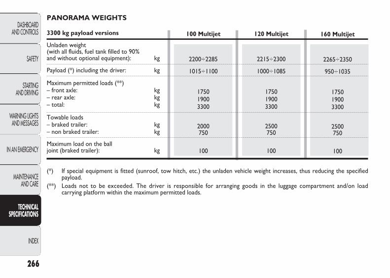
266
DASHBOARD AND CONTROLS
SAFETY
STARTING AND DRIVING
WARNING LIGHTSAND MESSAGES
IN AN EMERGENCY
MAINTENANCE AND CARE
TECHNICAL SPECIFICATIONS
INDEX
120 Multijet
2215÷2300
1000÷1085
175019003300
2500750
100
160 Multijet
2265÷2350
950÷1035
175019003300
2500750
100
PANORAMA WEIGHTS
3300 kg payload versions
Unladen weight (with all fluids, fuel tank filled to 90% and without optional equipment): kg
Payload (*) including the driver: kg
Maximum permitted loads (**)– front axle: kg– rear axle: kg– total: kg
Towable loads– braked trailer: kg– non braked trailer: kg
Maximum load on the ball joint (braked trailer): kg
(*) If special equipment is fitted (sunroof, tow hitch, etc.) the unladen vehicle weight increases, thus reducing the specifiedpayload.
(**) Loads not to be exceeded. The driver is responsible for arranging goods in the luggage compartment and/on loadcarrying platform within the maximum permitted loads.
100 Multijet
2200÷2285
1015÷1100
175019003300
2000750
100
223-276 DUCATO LUM EN 12-02-2010 13:10 Pagina 266
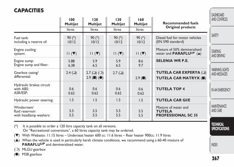
160Multijet
90 (*)10/12
11 (▼)
8.69.7
2.9 (■)
0.60.62
1.5
5.55.5
130Multijet
90 (*)10/12
11 (▼)
5.96.5
2.7 (❏)
0.60.62
1.5
5.55.5
120Multijet
90 (*)10/12
11 (▼)
5.96.5
2.7 (❏) (❍)2.9 (■) (●)
0.60.62
1.5
5.55.5
100Multijet
90 (*)10/12
11 (▼)
5.886.38
2.4 (❏)
0.60.62
1.5
5.55.5
267
DASHBOARD AND CONTROLS
SAFETY
STARTING AND DRIVING
WARNING LIGHTSAND MESSAGES
IN AN EMERGENCY
MAINTENANCE AND CARE
TECHNICAL SPECIFICATIONS
INDEX
Recommended fuels Original products
Diesel fuel for motor vehicles (EN 590 standard)
Mixture of 50% demineralisedwater and PARAFLUUP (▲)
SELENIA WR P.E.
TUTELA CAR EXPERYA (❏)TUTELA CAR MATRYX (■)
TUTELA TOP 4
TUTELA CAR GI/E
Mixture of water and TUTELA PROFESSIONAL SC 35
CAPACITIES
litres litres litres litres
Fuel tank: including a reserve of:
Engine cooling system:
Engine sump:Engine sump and filter:
Gearbox casing/differential:
Hydraulic brakes circuit with ABS:ASR/ESP:
Hydraulic power steering:
Windscreen/fluid reservoir:with headlamp washers:
(*) It is possible to order a 120 litre capacity tank on all versions. On “Recreational conversions”, a 60 litres capacity tank may be ordered.
(▼) With Webasto: 11.15 litres – Underseat heater 600 cc: 11.6 litres – Rear heater 900cc: 11.9 litres(▲) When the vehicle is used in particularly harsh climate conditions, we recommend using a 60-40 mixture of
PARAFLUUP and demineralised water.(❍) MLGU gearbox(●) M38 gearbox
223-276 DUCATO LUM EN 12-02-2010 13:10 Pagina 267
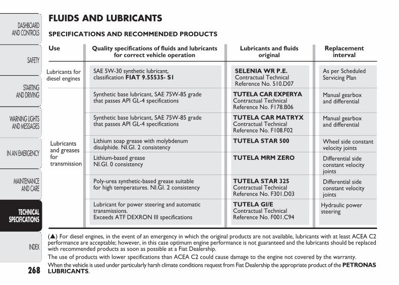
268
DASHBOARD AND CONTROLS
SAFETY
STARTING AND DRIVING
WARNING LIGHTSAND MESSAGES
IN AN EMERGENCY
MAINTENANCE AND CARE
TECHNICAL SPECIFICATIONS
INDEX
As per Scheduled Servicing Plan
Manual gearbox and differential
Manual gearbox and differential
Wheel side constantvelocity joints
Differential side constant velocityjoints
Differential sideconstant velocityjoints
Hydraulic powersteering
(▲) For diesel engines, in the event of an emergency in which the original products are not available, lubricants with at least ACEA C2performance are acceptable; however, in this case optimum engine performance is not guaranteed and the lubricants should be replacedwith recommended products as soon as possible at a Fiat Dealership.The use of products with lower specifications than ACEA C2 could cause damage to the engine not covered by the warranty.When the vehicle is used under particularly harsh climate conditions request from Fiat Dealership the appropriate product of the PETRONASLUBRICANTS.
SAE 5W-30 synthetic lubricant,classification FIAT 9.55535- S1
Synthetic base lubricant, SAE 75W-85 grade that passes API GL-4 specifications
Synthetic base lubricant, SAE 75W-85 grade that passes API GL-4 specifications
Lithium soap grease with molybdenum disulphide. NI.GI. 2 consistency
Lithium-based grease NI.GI. 0 consistency
Poly-urea synthetic-based grease suitable for high temperatures. NI.GI. 2 consistency
Lubricant for power steering and automatic transmissions. Exceeds ATF DEXRON III specifications
SELENIA WR P.E.Contractual TechnicalReference No. 510.D07
TUTELA CAR EXPERYA Contractual TechnicalReference No. F178.B06
TUTELA CAR MATRYX Contractual Technical Reference No. F108.F02
TUTELA STAR 500
TUTELA MRM ZERO
TUTELA STAR 325 Contractual TechnicalReference No. F301.D03
TUTELA GI/E Contractual Technical Reference No. F001.C94
Lubricants fordiesel engines
Lubricants and greases for transmission
FLUIDS AND LUBRICANTS
SPECIFICATIONS AND RECOMMENDED PRODUCTS
Use Quality specifications of fluids and lubricants Lubricants and fluids Replacementfor correct vehicle operation original interval
223-276 DUCATO LUM EN 12-02-2010 13:10 Pagina 268

269
DASHBOARD AND CONTROLS
SAFETY
STARTING AND DRIVING
WARNING LIGHTSAND MESSAGES
IN AN EMERGENCY
MAINTENANCE AND CARE
TECHNICAL SPECIFICATIONS
INDEX
Hydraulic brakes and clutch hydrauliccontrols
Cooling circuits percentage of use: 50% water 50% PARAFLUUP (❑)
To be mixed with diesel (25 cc per 10 litres)
To be used neat or dilute in screen washer systems
Synthetic fluid, NHTSA n° 116 DOT 4, ISO 4925 SAE J-1704, CUNA NC 956- 01. FIAT classification 9.55597.
Red protective with antifreeze action, based on inhibited monoethyl glycol with organic formula.Exceeds CUNA NC 956-16, ASTM D 3306specifications. FIAT classification 9.555323
Additive for diesel fuel, protecting Diesel engines
Mixture of spirits and surfactants.Exceeds CUNA NC 956-11 specifications.FIAT classification 9.55522.
Brake fluid
Protectiveagent for radiators
Dieseladditive
Windscreenwasher fluid
(*) IMPORTANT Do not use fluids with different specifications for topping up or mixing.(❑) When the vehicle is used under particularly harsh climate conditions, we recommend using a mixture of 60% PARAFLUUP
and 40% demineralised water.
TUTELA TOP 4 Contractual Technical Reference No. F001.A93
PARAFLUUP (*) Contractual Technical Reference No. F101.M01
TUTELA DIESEL ART Contractual Technical Reference No. F601.L06
TUTELA PROFESSIONAL SC 35 Contractual TechnicalReference No. F201.D02
Use Quality specifications of fluids and lubricants Lubricants and fluids Replacementfor correct vehicle operation original interval
223-276 DUCATO LUM EN 12-02-2010 13:10 Pagina 269
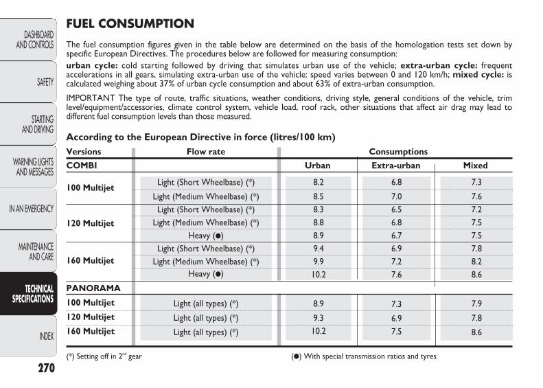
7.3
6.97.5
7.9
7.8
8.6
Light (all types) (*)
Light (all types) (*)
Light (all types) (*)
8.9
9.310.2
Light (Short Wheelbase) (*)
Light (Medium Wheelbase) (*)Light (Short Wheelbase) (*)
Light (Medium Wheelbase) (*)Heavy (●)
Light (Short Wheelbase) (*)Light (Medium Wheelbase) (*)
Heavy (●)
8.2
8.58.38.88.99.49.910.2
6.8
7.06.56.86.76.97.27.6
7.3
7.67.27.57.57.88.28.6
According to the European Directive in force (litres/100 km)Versions Flow rate Consumptions
COMBI Urban Extra-urban Mixed
PANORAMA
100 Multijet
120 Multijet
160 Multijet
(*) Setting off in 2nd gear (●) With special transmission ratios and tyres
270
DASHBOARD AND CONTROLS
SAFETY
STARTING AND DRIVING
WARNING LIGHTSAND MESSAGES
IN AN EMERGENCY
MAINTENANCE AND CARE
TECHNICAL SPECIFICATIONS
INDEX
FUEL CONSUMPTION
The fuel consumption figures given in the table below are determined on the basis of the homologation tests set down byspecific European Directives. The procedures below are followed for measuring consumption:urban cycle: cold starting followed by driving that simulates urban use of the vehicle; extra-urban cycle: frequentaccelerations in all gears, simulating extra-urban use of the vehicle: speed varies between 0 and 120 km/h; mixed cycle: iscalculated weighing about 37% of urban cycle consumption and about 63% of extra-urban consumption.
IMPORTANT The type of route, traffic situations, weather conditions, driving style, general conditions of the vehicle, trimlevel/equipment/accessories, climate control system, vehicle load, roof rack, other situations that affect air drag may lead todifferent fuel consumption levels than those measured.
100 Multijet
120 Multijet
160 Multijet
223-276 DUCATO LUM EN 12-02-2010 13:10 Pagina 270

271
DASHBOARD AND CONTROLS
SAFETY
STARTING AND DRIVING
WARNING LIGHTSAND MESSAGES
IN AN EMERGENCY
MAINTENANCE AND CARE
TECHNICAL SPECIFICATIONS
INDEX
208
206226
193
200190199199207216226
CO2 EMISSIONS
The CO2 emission levels at the exhaust given in the following tables refer to combined consumption.
100 Multijet
120 Multijet
160 Multijet
Light (all types) (*)
Light (all types) (*)
Light (all types) (*)
Light (Short Wheelbase) (*)
Light (Medium Wheelbase) (*)Light (Short Wheelbase) (*)
Light (Medium Wheelbase) (*)Heavy (●)
Light (Short Wheelbase) (*)Light (Medium Wheelbase) (*)
Heavy (●)
According to the European Directive in force (g/km)Versions Flow rate Emissions
COMBI
PANORAMA
100 Multijet
120 Multijet
160 Multijet
(*) Setting off in 2nd gear (●) With special transmission ratios and tyres
223-276 DUCATO LUM EN 12-02-2010 13:10 Pagina 271
272
DASHBOARD AND CONTROLS
SAFETY
STARTING AND DRIVING
WARNING LIGHTSAND MESSAGES
IN AN EMERGENCY
MAINTENANCE AND CARE
TECHNICAL SPECIFICATIONS
INDEX
ARRANGEMENTS FOR DEALING WITH THE VEHICLE AT THE END OF ITS LIFE
Fiat has been committed for many years to safeguarding the environment through the constant improvement of its productionprocesses and manufacturing products that are increasingly compatible with the ecosystem.
To assure customers of the best possible service in terms of respecting environmental laws and in response to EuropeanDirective 2000/53/EC governing vehicles at the end of their life, Fiat is offering their customers the opportunity of handingover their vehicle* at the end of its life without incurring any additional costs.
The European Directive sets out that when the vehicle is handed over the last keeper or owner should not incur any expensesas a result of its market value.
In particular, in almost all European Union countries, until 1st January 2007, vehicles registered after 1st July 2002 will becollected free of charge, whilst from 2007 collection will be free of charge irrespective of the year of registration as long as thevehicle contains its basic components (in particular, the engine and bodywork) and has no additional waste.
To hand your vehicle over at the end of its life without extra cost, contact one of our Fiat dealerships or authorised collectionand scrapping centres.
These centres have been carefully chosen to offer high quality service for the collection, treatment and recycling of unusedvehicles with respect to the environment.
You can find further information on these collection and scrapping centres either from a Fiat and Fiat Commercial VehicleDealership or by calling the freephone number 00800 3428 0000 or on the Fiat website.
* Vehicle for transporting passengers with a maximum of nine seats with a total permitted weight of 3.5 t
223-276 DUCATO LUM EN 12-02-2010 13:10 Pagina 272

273
DASHBOARD AND CONTROLS
SAFETY
STARTING AND DRIVING
WARNING LIGHTSAND MESSAGES
IN AN EMERGENCY
MAINTENANCE AND CARE
TECHNICAL SPECIFICATIONS
INDEX
OFFICIAL TYPE APPROVALS
223-276 DUCATO LUM EN 12-02-2010 13:10 Pagina 273
274
DASHBOARD AND CONTROLS
SAFETY
STARTING AND DRIVING
WARNING LIGHTSAND MESSAGES
IN AN EMERGENCY
MAINTENANCE AND CARE
TECHNICAL SPECIFICATIONS
INDEX
Pagine_ITA.indd 1 18-05-2005 11:53:40
223-276 DUCATO LUM EN 12-02-2010 13:10 Pagina 274
®
Always ask your mechanic for ®
Pagine_ITA.indd 1 18-05-2005 11:53:40
In the heart of your engine.
223-276 DUCATO LUM EN 12-02-2010 13:10 Pagina 275
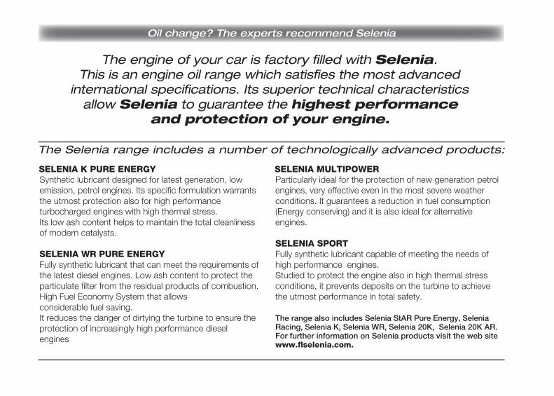
The engine of your car is factory filled with Selenia.
Oil change? The experts recommend Selenia
This is an engine oil range which satisfies the most advancedinternational specifications. Its superior technical characteristics
allow Selenia to guarantee the highest performanceand protection of your engine.
The Selenia range includes a number of technologically advanced products:
SELENIA K PURE ENERGY
Pagine_ITA.indd 4 18-05-2005 11:54:19
Synthetic lubricant designed for latest generation, low emission, petrol engines. Its specific formulation warrants the utmost protection also for high performance turbocharged engines with high thermal stress. Its low ash content helps to maintain the total cleanliness of modern catalysts.
SELENIA WR PURE ENERGY Fully synthetic lubricant that can meet the requirements of the latest diesel engines. Low ash content to protect the particulate filter from the residual products of combustion. High Fuel Economy System that allows considerable fuel saving. It reduces the danger of dirtying the turbine to ensure the protection of increasingly high performance diesel engines
SELENIA MULTIPOWERParticularly ideal for the protection of new generation petrol engines, very effective even in the most severe weather conditions. It guarantees a reduction in fuel consumption (Energy conserving) and it is also ideal for alternative engines.
SELENIA SPORTFully synthetic lubricant capable of meeting the needs of high performance engines.Studied to protect the engine also in high thermal stress conditions, it prevents deposits on the turbine to achieve the utmost performance in total safety.
The range also includes Selenia StAR Pure Energy, Selenia Racing, Selenia K, Selenia WR, Selenia 20K, Selenia 20K AR.For further information on Selenia products visit the web site www.flselenia.com.
223-276 DUCATO LUM EN 12-02-2010 13:10 Pagina 276

277
DASHBOARD AND CONTROLS
SAFETY
STARTING AND DRIVING
WARNING LIGHTSAND MESSAGES
IN AN EMERGENCY
MAINTENANCE AND CARE
TECHNICAL SPECIFICATIONS
INDEX
Battery
– battery disconnection function ............................ 86
– battery recharging ..........196
– inspecting the charge ....213
– jump starting ...................165
– replacement ....................214
Body (marking) .....................224
Body versions .......................225
Bodywork
– maintenance ....................219
– version codes ..................225
Bonnet ...................................104
Brake Assist (emergency brak-ing assistance) .....................110
Brakes
– fluid level ..........................210
– specifications ...................228
Bulb (replacement)
– bulb types ........................178
– general information .......177
Bulb replacement
– ceiling lights .....................187
– front lights .......................180
– rear lights .........................184
Car maintenance and care ...............................199
– heavy use of the vehicle ..............................204
– scheduled maintenance ..199
– scheduled Maintenance Plan ...........200
– scheduled servicing ........204
Carrying children safely ......128
ABS .......................................108
ABS system ...........................108
Accessories purchased by the owner ......................118
Additional rear air conditioning ........................ 71
Additional rear heating ....... 71
Air filter .................................212
Ashtray .................................. 90
ASR .........................................112
– on/off ................................112
ASR system ...........................112
Automatic climate control ................................. 58
Automatic headlight sensor(dusk sensor) ...................... 74
INDEX
277-284 DUCATO LUM EN 12-02-2010 13:14 Pagina 277

278
DASHBOARD AND CONTROLS
SAFETY
STARTING AND DRIVING
WARNING LIGHTSAND MESSAGES
IN AN EMERGENCY
MAINTENANCE AND CARE
TECHNICAL SPECIFICATIONS
INDEX
Carrying children safely– child seats ........................128– preparation for Isofix
child seat ..........................132Ceiling light – front .................................. 81– rear ................................... 82
Changing a wheel .................166Chassis marking ...................224Checking fluid levels ...........205Child seats (compliance for use) .........131
Cigar lighter .......................... 90Clutch ....................................227CO2 emissions .....................271Code card ............................. 5 Compartment under passenger side front seat ... 88
Consumptions– engine oil .........................207– fuel ....................................270
Control buttons ................... 83
Controls ................................ 83
Cruise Control .................... 78
Cruise Control (constantspeed regulator) ................ 78
Current socket .................... 91
Dashboard ........................... 3
Dashboard and controls .... 3
Dead lock (device)
– on/off ................................ 99
Desk/lectern ......................... 91
Digital display ....................... 18
Dimensions ...........................232
Dipped beam headlights
– bulb replacement ...........182
– control ............................. 72
Dipped headlamps
– bulb replacement ...........182
– control ............................. 72
Direction indicators
– bulb replacement ...........182
– control ............................. 73
Direction indicators
– control ............................. 73
– front bulb replacement ..180
– rear bulb replacement ...184
– side bulb replacement ...182
Door compartment cups ... 90
Door lock............................... 85
Doors ..................................... 97
Electric windows
– controls .............................103
Electronic alarms .................. 10
Emergency situation.............165
Engine
– features..............................226
– identification code .........225
– marking ............................224
277-284 DUCATO LUM EN 12-02-2010 13:14 Pagina 278
279
DASHBOARD AND CONTROLS
SAFETY
STARTING AND DRIVING
WARNING LIGHTSAND MESSAGES
IN AN EMERGENCY
MAINTENANCE AND CARE
TECHNICAL SPECIFICATIONS
INDEX
Filling the tank ......................121
Fix & Go (device) ................172
Fix&Go Automatic tyre repair kit ..............................172
Flap on bench ....................... 43
Flashing the headlights ........ 73
Fluids and lubricants ...........268
Fog lights
– bulb replacement ...........183
– control buttons .............. 83
Fog lights
– bulb replacement ...........183
– control buttons .............. 83
Follow me home (device) ... 74
Front airbags .........................135
Front armrest ....................... 39
Front ceiling lights
– bulb replacement ...........187
– control ............................. 81
Fuel
– fuel cut off switch .......... 86
– fuel gauge ......................... 16
Fuel cap ..................................121
Fuel cut off switch ............... 86
Fuel flap .................................121
Fuel level ............................... 16
Fuel reserve ..........................159
Fuel savings ...........................146
Fuel system ...........................227
Fuse control units (location) .............................190
Fuses
– fuse list .............................192
– fuse location (control units) .................190
– fuse replacement ............189
Fuses (if a fuse blows) .........189
Engine codes .........................225Engine compartment – bonnet opening/closing ...104– checking fluid levels .......205– washing .............................221
Engine coolant temperature indicator .............................. 16
Engine oil– consumption ...................207– level check .......................207– technical specifications ...268
Engine oil level indicator .... 17Environment protection ....122EOBD (system) ....................114EOBD system .......................114ESP (system) .........................110ESP system ............................110External lights ....................... 72
Fiat CODE (The system) . 4Fiat CODE system .............. 4
277-284 DUCATO LUM EN 12-02-2010 13:14 Pagina 279
280
DASHBOARD AND CONTROLS
SAFETY
STARTING AND DRIVING
WARNING LIGHTSAND MESSAGES
IN AN EMERGENCY
MAINTENANCE AND CARE
TECHNICAL SPECIFICATIONS
INDEX
Gearbox
– using the manual gearbox ............................144
Glove compartment ........... 88
Glove compartments .......... 87
Handbrake ...........................143
Handbrake lever ..................143
Hazard warning lights ......... 83
Headlamps
– alignment corrector ......107
– bulb replacement ...........180
Headlight angle correction ..107
Headlight washers
– control ............................. 78
Headlights .............................107
– headlamp alignment corrector .........................107
– light beam direction ......107
Headrest
– front .................................. 45
Heating and ventilation ...... 49
Heating system ..................... 49
Hill Holder (system) ...........111
Hill Holder system ..............111
Identification data ...............223
Ignition switch ...................... 12
Installation of electrical/ electronic devices ..............119
Instrument panel .................. 14
Interior fittings ..................... 87
Interiors .................................221
Isofix .......................................132
Key with remote control ... 6
Key without remote control ................................. 8
Lectern ................................. 91
Levels
– brake fluid level ..............210
– engine coolant level .......208
– engine oil level ................207
– power steering fluid level ..........................211
– windscreen/rearscreen/headlamp washer fluid level ...................................209
Light clusters
– front (bulb replacement) ........180
– rear (bulb replacement)..........184
Load advice ...........................145
Load limiters .........................125
Lubricants (features) ...........268
277-284 DUCATO LUM EN 12-02-2010 13:14 Pagina 280

281
DASHBOARD AND CONTROLS
SAFETY
STARTING AND DRIVING
WARNING LIGHTSAND MESSAGES
IN AN EMERGENCY
MAINTENANCE AND CARE
TECHNICAL SPECIFICATIONS
INDEX
Main beam headlights
– bulb replacement ...........182
– control ............................. 72
Main beam headlights
– bulb replacement ...........181
– control ............................. 72
– flashing .............................. 73
Maintenance and cleaning
– bodywork ........................219
– car interior ......................221
– engine compartment .....221
– plastic parts .....................222
– seats ..................................222
– windows ...........................221
Maintenance programme
Manual air conditioning ...... 53
Moving footboard ................101
MSR (system) .......................112
MSR system ..........................112
Multifunction display ........... 24
Number plate light ..............186
Official type approval for radio frequency remote control ..................273
On board instruments
– display ............................... 18
– engine coolant temperature .................... 16
– fuel level gauge ............... 16
– multifunction display ..... 24
– rev counter ..................... 15
– speedometer ................... 15
Operation at low temperatures ......................120
Paint ......................................220
Parking ...................................143
Parking sensors ....................115
Passenger compartment air vents ............................... 50
Performance .........................235
Plates
– bodywork paint ..............224
– identification data ...........223
Pollen filter ............................212
Preparation for Isofix child seat .............................132
Pretensioners .......................125
Programmed .........................200
Prolonged vehicle inactivity ..............................153
Protecting the environment ................122
Radio .....................................117
Radio frequency remote control: official approvals ..273
277-284 DUCATO LUM EN 12-02-2010 13:14 Pagina 281
282
DASHBOARD AND CONTROLS
SAFETY
STARTING AND DRIVING
WARNING LIGHTSAND MESSAGES
IN AN EMERGENCY
MAINTENANCE AND CARE
TECHNICAL SPECIFICATIONS
INDEX
Radio transmitters and mobile phones ............119
Rain sensor ........................... 77
Raising the vehicle ...............197
Rear ceiling lights
– bulb replacement ...........188
– control ............................. 82
Rear door with two flaps ...101
Rear foglights
– bulb replacement ...........185
– control buttons .............. 84
Rear partition ....................... 89
Rear view TV camera ......... 93
Rearview mirrors ................ 47
– electric ............................. 47
– exterior ............................ 47
– interior ............................. 47
Refilling the vehicle .............120
Refrigerated compartment .. 87
Rev counters ........................ 15
Rev counters ........................ 15Reversing lamp .....................184Roof rack bars (preparation) ......................106
Roof rack/ski rack ...............106
S.B.R. system .......................124Safety– carrying children safely ...128– Isofix child seat ...............132– seat belts ..........................123
Seat adjustment .................... 37Seat belts ...............................123– general information .......126– load limiters ....................125– maintenance ....................127– pretensioners ..................125– use .....................................123
Seats – adjustment ....................... 37– cleaning ............................222
Set-up menu ......................... 19
Side bags ................................137
Side lights
– control ............................. 72
– front bulb replacement ..180
– rear bulb replacement ..184
– side bulb replacement ...187
Sliding side door ..................100
Sliding side glass ...................100
Smart washing ...................... 76
Snow chains ..........................152
Speed block .......................... 96
Speedometer ........................ 15
Starting the engine ..............141
– bump starting ..................166
– emergency starting ........165
– ignition switch ................. 12
– jump starting ...................165
– procedure for diesel versions ............................141
277-284 DUCATO LUM EN 12-02-2010 13:14 Pagina 282
283
DASHBOARD AND CONTROLS
SAFETY
STARTING AND DRIVING
WARNING LIGHTSAND MESSAGES
IN AN EMERGENCY
MAINTENANCE AND CARE
TECHNICAL SPECIFICATIONS
INDEX
– stopping the engine .......142
– warming up the engine once started ....................142
Starting up and driving ........141
Steering
– specifications ...................228
– turning circle ...................228
Steering lock ......................... 13
Steering wheel adjustment .. 46
Sun visors .............................. 91
Supplementary heater ........ 64
Supplementary independentheater ................................... 65
Suspensions ...........................227
Symbols .................................. 4
Tachograph ......................... 96
Technical data ......................223
Third brake light ..................186
Top speed .............................235
Towing the vehicle ..............197
Towing trailers
– installing the tow hitch ..................................149
Transmission ........................227
Tray under the seat ............ 42
Trip computer ...................... 35
– trip button ....................... 36
Trip Computer
– sizes
Tyre inflation pressure .......231
Tyres
– reading the tyre code ...229
– replacement ....................166
– snow tyres .......................152
– standard ...........................230
Using the manual gearbox ................................136
Vehicle inactivity ................153
Ventilation ............................. 49
Warning lights and messages ......................155
Weights .................................236
Wheel
– replacement ....................166
Wheel geometry .................229
Wheel rims
– reading the rim code .....230
Window cleaning ................. 75
Windows (cleaning) ............221
Windscreen washer
– control ............................. 75
277-284 DUCATO LUM EN 12-02-2010 13:14 Pagina 283
284
DASHBOARD AND CONTROLS
SAFETY
STARTING AND DRIVING
WARNING LIGHTSAND MESSAGES
IN AN EMERGENCY
MAINTENANCE AND CARE
TECHNICAL SPECIFICATIONS
INDEX Fiat Group Automobiles S.p.A. - Customer Services - Technical Services - Service Engineering Largo Senatore G. Agnelli, 5 - 10040 Volvera - Torino (Italia)
Print no. 603.81.357 – 11/2009 – 6 edition
– fluid level ..........................209
Windscreen wiper
– blades ................................218
– control ............................. 75
– jets .....................................218
Windscreen wiper blades ...218
Wiring for radio system .....117
277-284 DUCATO LUM EN 12-02-2010 13:14 Pagina 284
The data contained in this publication is intended merely as a guide. FIAT reserves the right to modify the models and versions described in this booklet at any time for technical and commercial reasons.
If you have any further questions please consult your FIAT dealer. Printed in recycled paper without chlorine. O W N E R H A N D B O O K
F I A T D U C A T OENGLISH
DUCATO LUM GB 17-12-2008 9:57 Pagina 1