Embed Size (px)
Citation preview

Dual WatchDog Timer Board 092014-001-01
P r o d u c t B r i e f
______________________________________________________________________________________ SwitchDoc Labs, LLC, 20089 E Glenbrook Ave,, Liberty Lake, Washington 99016 - [email protected]
The SwitchDoc Labs Dual WatchDog Timer is designed to make small computer such as the Arduino and Raspberry Pi more reliable by detecting and recovering from computer or software malfunctions. It has two WatchDog Timers that
can be used independently or together to reset non-responsive computers. It directly can drive the Arduino Reset line, The Raspberry Pi B/B+ reset line or a to a relay.
Features and Benefits:
• Dual Independent WatchDog Timers • Arduino and Raspberry Pi Compatible • LED Timer State Indicators • 3.3V or 5V operation • Programmable timeout from 30-240
seconds • Open Collector or Pulse Driven Operation • Low Power • Low Cost • Full Test Code Supplied • Quantity Discounts Available • Immediate Availability
Theory of Operation Why do you need a external Hardware WatchDog on an Arduino or Raspberry Pi? The reason is the internal watchdog is disabled in the bootloader for the Arduino and the Raspberry Pi is difficult to use and is not the same as rebooting by turning the power on and off (the internal Raspberry Pi Watchdog does not reset all peripherals). The SwitchDoc Labs Dual WatchDog Timer is based on the 555 timer IC running in bi-stable mode. The 555 timer acts as a “one-shot” pulse generator. The pulse starts on power up or any time the trigger input is brought to ground. The setting of the TM1 potentiometer determines the length of the pulse (30-240 seconds). When the pulse ends the Arduino Reset output is taken to ground (and the PulseHigh output goes to VDD) for approximately 200ms. Then the cycle starts over again. If the timer input (JP2) is grounded (it should be normally in a high impedance state), then the pulse is started again. Therefore, if you pulse the timer input (Dog1 or Dog2) low before the timer expires, the pulse never ends, so the outputs
are never triggered. (ArduinoReset remains in a high-Z state and the Pulse Output remains in a 0 state). The two WatchDog timers are independent, however they can be used together. The Dog1 and Dog2 trigger inputs need to be wired together in this mode and triggered together. See Cascaded Timer Operation below. This mode allows the use of a bistable relay to turn a relay connected to the power input on a Raspberry Pi. A single timer may be used to drive a relay ( through a buffer transistor directly if 200ms is sufficient to trigger the relay and reset the device).

Contact: [email protected]
DualWatchDog_101914-V1.3
Operating Values
Min Max Unit
Vdd – Supply Voltage 3.3 5 V
Vi – Trigger Input Voltage 0 1/3* Vdd V
Iop – Operating Current 5 5.8 mA
Tout – Timeout Interval 30 240 sec Physical dimensions of board: 63.44mm x 64.33mm x 12mm(max). Mounting holes inset 3.5mm x3.5mm from each corner Pin Functions NAME PIN I/O DESCRIPTION
DOG1_TRIGGER JP2 / 1 I Resets WatchDog 1. Should be held in high-impedance and then taken to ground to “pat the dog”.
DOG2_TRIGGER JP2 / 2 I Resets WatchDog 2. Should be held in high-impedance and then taken to ground to “pat the dog”.
DOG1_ARDUINORESET JP3 / 1 O When WatchDog 1 triggers, this pin is pulled to GND for ~300ms. Otherwise high-impedance.
DOG1_PULSEHIGH JP3 / 2 O Active Low Output. Pulses High for ~300msec when the WatchDog is triggered.
DOG2_ARDUINORESET JP5 / 1 O When WatchDog 1 triggers, this pin is pulled to GND for ~300ms. Otherwise high-impedance.
DOG2_PULSEHIGH JP5 / 2 O Active Low Output. Pulses High for ~300msec when the WatchDog is triggered.
Setting the Timeout Interval
The timeout interval for each WatchDog timer is set by turning the respective TM1 / TM2 single turn potentiometer. It can be set from 30 seconds to 240 seconds. It is set by turning it over a 270 degree range. Applications The Dual WatchDog board can be used to reset any computer with some ingenuity. There are two modes of operation for the Dual WatchDog board.
Single Timer Operation To use a single timer on the WatchDog board, you connect a GPIO line to the DOG1_TRIGGER input. This GPIO pin needs to be set
to high-impedance mode (input mode) when the trigger is not being applied to avoid interfering with the charging process of the 555 timer. For the Arduino, the trigger code (“Patting the Dog”) looks like this:

Contact: [email protected]
DualWatchDog_101914-V1.3
void ResetWatchdog1() { pinMode(RESET_WATCHDOG1, OUTPUT); delay(200); pinMode(RESET_WATCHDOG1, INPUT); Serial.println("Watchdog1 Reset"); }
To reset the WatchDog timer you would call this routine on a regular basis, always keeping the interval between calls less than you have set the Timeout for the respective WatchDog timer. If you don't call the reset code before the timeout experation, then if your are using Dog1, DOG1_ARDUINORESET would be pulled to ground for ~300ms and the DOG1_PULSEHIGH will pulse high for ~300ms. Cascaded Timer Operation The purpose of Cascaded Timer Operation is to generate two pulses separated by the Timeout interval of DOG2 when the DOG1 Timeout expires. This might be used to trigger a latched relay off and on to reset a Raspberry Pi. There are three requirements to use Cascaded Timer Operation.
1. DOG1_TRIGGER and DOG2_TRIGGER should be tied together or triggered at the same time
2. DOG1 Timeout must be greater than DOG2 Timeout. The difference between the Timeouts will be the time between pulses on DOG1_PULSEHIGH and DOG2_PULSEHIGH.
3. The system that is reset must come up again and start triggering the WatchDogs before the DOG2 Timeout
Interval occurs again from the initial Timeout. The reset system should come up again before DOG2Time out has expired (although depending on your circuit, it may not matter).
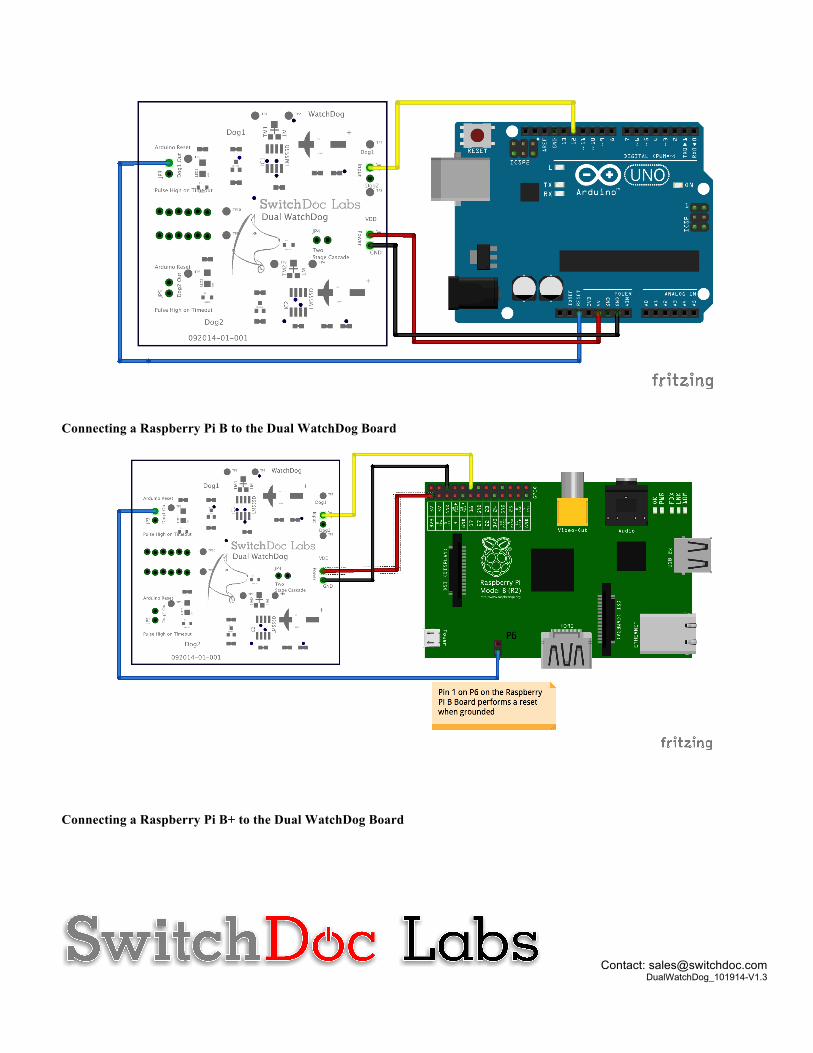
Resetting an Arduino Compatible Device Adding the WatchDog to an Arduino is simple. You connect the DOG1_ARDUINORESET directly to the RESET pin on the Arduino and connect the DOG1_TRIGGER to any available GPIO pin on the Arduino. You then use the code shown above to periodically pull the DOG1_TRIGGER to ground to keep the WatchDog from timing out. Resetting a Raspberry Pi Resetting a Raspberry PI Model A/B/B+ externally requires turning the power on and off. This can be driving a single relay connected through the power supply leads (buffering the Relay coil. Relay coils can take a lot of current to activate (> 50ma). There are many such relay boards available from companies such as Sainsmart. Using the WatchDog in Cascaded Timer operation is an excellent way of driving a low power latching relay such as those available from Ciseco (http://shop.ciseco.co.uk/3v-to-5v-bistable-latching-relay-kit/). A variety of solid state solutions can also be used. Raspberry Pi Model B/B+ Reset Header All of the above techniques can be used for the Model B/B+ but there is an additional option using the P6 header. You can connect pin 1 of the P6 (square Pad) on the B and the Run Pin (square pad) on the B+ header directly to the DOG1_ARDUINORESET line and it will reset the Raspberry Pi just as the Arduino. Connecting an Arduino to the Dual WatchDog Board
Contact: [email protected]
DualWatchDog_101914-V1.3
Connecting a Raspberry Pi B to the Dual WatchDog Board
Connecting a Raspberry Pi B+ to the Dual WatchDog Board

Contact: [email protected]
DualWatchDog_101914-V1.3
Testing The Dual WatchDog Board with an Arduino Below is a Fritzing diagram showing how to connect the Dual WatchDog board to an Arduino for testing using the Demo software SD_DUALWATCHDOG_TEST.ino on http://github.com/switchdoclabs/DualWatchDogBoard