Embed Size (px)
Citation preview

Advance Technologies; Automate the World.
Manual Rev. 3.00
Revision Date: June 28, 2006
Part No: 50-11109-1010
NuCOM©PCI-7841/cPCI-7841/PM-7841
Dual-Port Isolated CAN Interface Card
User’s Manual

Copyright 2006 ADLINK TECHNOLOGY INC.
All Rights Reserved.
The information in this document is subject to change without priornotice in order to improve reliability, design, and function and doesnot represent a commitment on the part of the manufacturer.
In no event will the manufacturer be liable for direct, indirect, spe-cial, incidental, or consequential damages arising out of the use orinability to use the product or documentation, even if advised ofthe possibility of such damages.
This document contains proprietary information protected by copy-right. All rights are reserved. No part of this manual may be repro-duced by any mechanical, electronic, or other means in any formwithout prior written permission of the manufacturer.
Trademarks
NuDAQ, NuIPC, DAQBench are registered trademarks of ADLINKTECHNOLOGY INC.
Product names mentioned herein are used for identification pur-poses only and may be trademarks and/or registered trademarksof their respective companies.

Getting Service from ADLINKCustomer Satisfaction is top priority for ADLINK Technology Inc.Please contact us should you require any service or assistance.
ADLINK TECHNOLOGY INC.Web Site: http://www.adlinktech.comSales & Service: [email protected]: +886-2-82265877FAX: +886-2-82265717Address: 9F, No. 166, Jian Yi Road, Chungho City,
Taipei, 235 Taiwan
Please email or FAX this completed service form for prompt andsatisfactory service.
Company Information
Company/OrganizationContact PersonE-mail AddressAddressCountryTEL FAX:Web Site
Product InformationProduct Model
EnvironmentOS:M/B: CPU:Chipset: BIOS:
Please give a detailed description of the problem(s):


Table of Contents i
Table of ContentsTable of Contents..................................................................... i
List of Tables.......................................................................... iii
List of Figures ........................................................................ iv
1 Introduction ........................................................................ 11.1 PCI/cPCI/PM-7841 Features ............................................... 11.2 Applications ......................................................................... 31.3 Specifications....................................................................... 4
2 Installation .......................................................................... 72.1 Before Installing the PCI/cPCI/PM-7841.............................. 72.2 Installing PCI-7841 .............................................................. 72.3 Installing cPCI-7841............................................................. 92.4 Installing PM-7841 ............................................................. 102.5 Jumper and DIP Switch Description .................................. 122.6 Base Address Setting ........................................................ 122.7 IRQ Level Setting............................................................... 14
3 Function Reference.......................................................... 153.1 Functions Table ................................................................. 15
PORT_STRUCT structure define ................................. 16CAN_PACKET structure define .................................... 18Members ....................................................................... 18DEVICENET_PACKET structure define ....................... 19Members ....................................................................... 19
3.2 CAN LAYER Functions...................................................... 20CAN-layer Card Initialization Functions ........................ 20PM7841_Install(base, irq_chn, 0xd000) ....................... 20GetDriverVersion() ........................................................ 20CanOpenDriver() .......................................................... 21CanCloseDriver() .......................................................... 21CanConfigPort() ............................................................ 22CanDetectBaudrate() .................................................... 23CanRead() .................................................................... 24CanWrite() .................................................................... 24CAN-layer I/O Functions ............................................... 24

ii Table of Contents
CanEnableReceive() ..................................................... 24CanDisableReceive() .................................................... 25CanSendMsg() .............................................................. 25CanRcvMsg() ................................................................ 26CAN-layer Status Functions ......................................... 27CanClearOverrun() ....................................................... 27CanClearRxBuffer() ...................................................... 28CanClearTxBuffer() ....................................................... 28CanGetErrorCode() ...................................................... 29CanSetErrorWarningLimit() .......................................... 31CanGetErrorWarningLimit() .......................................... 32CanGetRxErrorCount() ................................................. 32CanGetTxErrorCount() ................................................. 33CanSetTxErrorCount() .................................................. 33CanGetPortStatus() ...................................................... 34CanGetLedStatus() ....................................................... 35CanSetLedStatus() ....................................................... 35CanGetRcvCnt() ........................................................... 36Error and Event Handling Functions ............................. 37CanInstallCallBack() ..................................................... 37CanRemoveCallBack() ................................................. 38CanCloseDriver(handle); .............................................. 40CanGetReceiveEvent() ................................................. 40CanInstallEvent() .......................................................... 41
Warranty Policy ..................................................................... 43

List of Tables iii
List of TablesTable 1-1: PCI-7841 Specifications ........................................... 4Table 1-2: cPCI-7841 Specifications ......................................... 4Table 1-3: PM-7841 Specifications ............................................ 5

iv List of Figures
List of FiguresFigure 2-1: Default Base Address Configuration........................ 13Figure 2-2: IRQ Settings ............................................................ 14

Introduction 1
1 IntroductionThe PCI/cPCI/PM-7841 is a Controller Area Network (CAN) inter-face card used for industrial PC with PCI, Compact-PCI, andPC104 bus. It supports dual ports CAN’s interface that can runindependently or bridged at the same time. The built-in CAN con-troller provides bus arbitration and error detection with auto cor-rection and re-transmission function. The PCI cards are plug andplay therefore it is not necessary to set any jumper for matchingthe PC environment.
The CAN (Controller Area Network) is a serial bus system origi-nally developed by Bosch for use in automobiles, is increasingbeing used in industry automation. It multi-master protocol, real-time capability, error correction and high noise immunity make itespecially suited for intelligent I/O devices control network.
The PCI/cPCI/PM-7841 is programmed by using the ADLINK‘ssoftware library. The programming of this PCI card is as easy asAT bus add-on cards.
1.1 PCI/cPCI/PM-7841 FeaturesThe PCI-7841 is a Dual-Port Isolated CAN Interface Card with thefollowing features:
Two independent CAN network operationBridge function supportsCompatible with CAN specification 2.0 parts A and BOptically isolated CAN interface up to 2500 Vrms isolation protectionDirect memory mapping to the CAN controllersPowerful master interface for CANopen, DeviceNet and SDS application layer protocolUp to 1Mbps programmable transfer rateSupports standard DeviceNet data rates 125, 250 and 500 KbpsPCI bus plug and playDOS library and examples included

2 Introduction
The cPCI-7841 is a Dual-Port Isolated CAN Interface Card withthe following features:
Two independent CAN network operationBridge function supportsCompatible with CAN specification 2.0 parts A and BOptically isolated CAN interface up to 2500 Vrms isolation protectionDirect memory mapping to the CAN controllersPowerful master interface for CANopen, DeviceNet and SDS application layer protocolUp to 1Mbps programmable transfer rateSupports standard DeviceNet data rates 125, 250 and 500 KbpsPCI bus plug and playcompact-PCI industry busDOS library and examples included
The PM-7841 is a Dual-Port Isolated CAN Interface Card with thefollowing features:
Two independent CAN network operationBridge function supportsCompatible with CAN specification 2.0 parts A and BOptically isolated CAN interface up to 2500 Vrms isolation protectionDirect memory mapping to the CAN controllersPowerful master interface for CANopen, DeviceNet and SDS application layer protocolUp to 1Mbps programmable transfer rateSupports standard DeviceNet data rates 125, 250 and 500 KbpsDIP-Switch for base address configurationSoftware Programmable Memory-Mapped AddressPC-104 industry form factorDOS library and examples included

Introduction 3
1.2 ApplicationsIndustry automation Industry process monitoring and controlManufacture automationProduct testing
4 Introduction
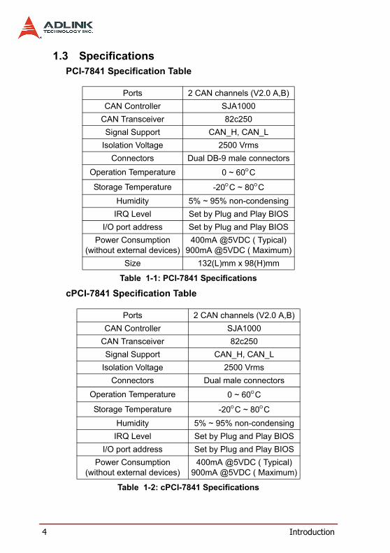
1.3 SpecificationsPCI-7841 Specification Table
cPCI-7841 Specification Table
Ports 2 CAN channels (V2.0 A,B)CAN Controller SJA1000
CAN Transceiver 82c250Signal Support CAN_H, CAN_L
Isolation Voltage 2500 VrmsConnectors Dual DB-9 male connectors
Operation Temperature 0 ~ 60°CStorage Temperature -20°C ~ 80°C
Humidity 5% ~ 95% non-condensingIRQ Level Set by Plug and Play BIOS
I/O port address Set by Plug and Play BIOSPower Consumption
(without external devices)400mA @5VDC ( Typical)
900mA @5VDC ( Maximum)Size 132(L)mm x 98(H)mm
Table 1-1: PCI-7841 Specifications
Ports 2 CAN channels (V2.0 A,B)CAN Controller SJA1000
CAN Transceiver 82c250Signal Support CAN_H, CAN_L
Isolation Voltage 2500 VrmsConnectors Dual male connectors
Operation Temperature 0 ~ 60°CStorage Temperature -20°C ~ 80°C
Humidity 5% ~ 95% non-condensingIRQ Level Set by Plug and Play BIOS
I/O port address Set by Plug and Play BIOSPower Consumption
(without external devices)400mA @5VDC ( Typical)
900mA @5VDC ( Maximum)
Table 1-2: cPCI-7841 Specifications

Introduction 5
PM-7841 Specification Table
Size 132(L)mm x 98(H)mm
Ports 2 CAN channels (V2.0 A,B)CAN Controller SJA1000
CAN Transceiver 82c250/82c251Signal Support CAN_H, CAN_L
Isolation Voltage 1000 VrmsConnectors Dual 5 male connectors
Operation Temperature 0 ~ 60°CStorage Temperature -20°C ~ 80°C
Humidity 5% ~ 95% non-condensingIRQ Level Set by Jumper
I/O port address Set by DIP SwitchMemory Mapped Space 128 Bytes by Software
Power Consumption(without external devices)
400mA @5VDC ( Typical)900mA @5VDC ( Maximum)
Size 90.17(L)mm x 95.89(H)mm
Table 1-3: PM-7841 Specifications
Table 1-2: cPCI-7841 Specifications

6 Introduction

Installation 7
2 InstallationThis chapter describes how to install the PCI/cPCI/PM-7841. Atfirst, the contents in the package and unpacking information thatyou should be careful are described.
2.1 Before Installing the PCI/cPCI/PM-7841Your PCI/cPCI/PM-7841 card contains sensitive electronic compo-nents that can be easily damaged by static electricity.
The card should be done on a grounded anti-static mat. The oper-ator should be wearing an anti-static wristband, grounded at thesame point as the anti-static mat.
Inspect the card module carton for obvious damage. Shipping andhandling may cause damage to your module. Be sure there are noshipping and handing damages on the module before processing.
After opening the card module carton, exact the system moduleand place it only on a grounded anti-static surface component sideup.
Note: DO NOT APPLY POWER TO THE CARD IF IT HAS BEEN DAMAGED.
You are now ready to install your PCI/cPCI/PM-7841.
2.2 Installing PCI-7841What you have:
In addition to this User's Manual, the package includes the follow-ing items:
PCI-7841 Dual Port PCI Isolated CAN Interface CardADLINK CD-ROM
If any of these items is missing or damaged, contact the dealerfrom whom you purchased the product. Save the shipping materi-als and carton in case you want to ship or store the product in thefuture.
8 Installation
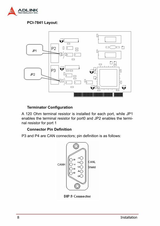
PCI-7841 Layout:
Terminator ConfigurationA 120 Ohm terminal resistor is installed for each port, while JP1enables the terminal resistor for port0 and JP2 enables the termi-nal resistor for port 1
Connector Pin DefinitionP3 and P4 are CAN connectors; pin definition is as follows:

Installation 9
2.3 Installing cPCI-7841What you have
In addition to this User's Manual, the package includes the follow-ing items:
cPCI-7841 Dual Port Compact-PCI Isolated CAN Interface CardADLINK CD-ROM
If any of these items is missing or damaged, contact the dealerfrom whom you purchased the product. Save the shipping materi-als and carton in case you want to ship or store the product in thefuture.
cPCI-7841 Layout
Terminator ConfigurationA 120 Ohm terminal resistor is installed for each port, while JP1enables the terminal resistor for port0 and JP2 enables the termi-nal resistor for port 1

10 Installation
Connector Pin DefinitionJ1 and J2 are CAN connectors; pin definition is as follows:
2.4 Installing PM-7841What you have
In addition to this User's Manual, the package includes the follow-ing items:
PM-7841 Dual Port PC-104 Isolated CAN Interface CardADLINK CD-ROM
If any of these items is missing or damaged, contact the dealerfrom whom you purchased the product. Save the shipping materi-als and carton in case you want to ship or store the product in thefuture.

Installation 11
PM-7841 Layout
Terminator ConfigurationA 120 Ohm terminal resistor is installed for each port, while JP1enables the.
terminal resistor for port0 and JP2 enables the terminal resistor forport 1.

12 Installation
Connector Pin DefineJ1 and J2 are CAN connectors; pin definition is as follows:
2.5 Jumper and DIP Switch DescriptionYou can configure the output of each channel and base addressby setting jumpers and DIP switches on the PM-7841. The card'sjumpers and switches are preset at the factory. Under normal cir-cumstances, you should not need to change the jumper settings.
A jumper switch is closed (sometimes referred to as "shorted")with the plastic cap inserted over two pins of the jumper. A jumperis open with the plastic cap inserted over one or no pin(s) of thejumper.
2.6 Base Address SettingThe PM-7841 requires 16 consecutive address locations in I/Oaddress space. The base address of the PM-7841 is restricted bythe following conditions.
1. The base address must be within the range 200hex to3F0hex.
2. The base address should not conflict with any PCreserved I/O address.
The PM-7841's I/O port base address is selectable by an 5 posi-tion DIP switch SW1 ( refer to Table 2.1). The address settings forI/O port from Hex 200 to Hex 3F0 is described in Table 2.2 below.The default base address of your PM-7841 is set to hex 200 in thefactory( see Figure below).

Installation 13
Figure 2-1: Default Base Address Configuration
(*): default setting ON : 0X: don't care OFF : 1
Note: A4,…, A9 correspond to PC-104(ISA) bus address lines.
SW1 : Base Address = 0x200
1 2 3 4 5
ON
A ( 8 7 6 5 4 )

14 Installation
2.7 IRQ Level SettingA hardware interrupt can be triggered by the external Interrupt sig-nal which is from JP3 ad JP4.
The jumper setting is specified as below:
Note: Be aware that there is no other add-on cards sharing the same interrupt level in the system.
Figure 2-2: IRQ Settings
(IRQ)
9 7 6 5 3 X 15 12 11 10
Interrupt Default Setting = IRQ15

Function Reference 15
3 Function ReferenceThe cPCI/PCI-7841 functions are organize into the following sec-tions:
CAN layer functionsCard Initialization and configuration functionsCAN layer I/O functionsCAN layer status functionsCAN layer Error and Event Handling functionsDeviceNet layer functionsSend and Receive packet functionsConnection establish and release functionsDeviceNet object class functions
The particular functions associated with each function are pre-sented in next page.
3.1 Functions TableCAN layer functions
Function Type Function NamePM-7841 Initial PM7841_Install()
GetDriverVersion()CanOpenDriver()CanCloseDriver()CanConfigPort()
CanDetectBaudrate()_7841_Read()_7841_Write()
CanEnableReceive()CanDisableReceive()
CanSendMsg()CanRcvMsg()
CanGetRcvCnt()

16 Function Reference
Note: only for compact PCI and PC-104 version.
PORT_STRUCT structure defineThe PORT_STRUCT structure defines the mode of id-mode,acceptance code, acceptance mask and baud rate of a physicalCAN port. It is used by the CanPortConfig(), and CanGetPortSta-tus() functions.
typedef struct _tagPORT_STRUCT{int mode; // 0 for 11-bit; 1 for 29-
bitDWORD accCode, accMask;int baudrate;BYTE brp, tseg1, tseg2;// ReservedBYTE sjw, sam; // Reserved}PORT_STRUCT;
CanClearOverrun()CanClearRxBuffer()CanClearTxBuffer()CanGetErrorCode()
CanGetErrorWarningLimit()CanSetErrorWarningLimit()
CanGetRxErrorCount()CanGetTxErrorCount()CanSetTxErrorCount()
CanGetPortStatus()CanGetLedStatus()1CanSetLedStatus()1
Error and Event handling functionsOperation System Function Name
DOSCanInstallCallBack()
CanRemoveCallBack()Windows 95/98/NT CanInstallEvent()

Function Reference 17
Membersmode: 0 means using 11-bit in CAN-ID field
1 means using 29-bit in CAN-ID field.
accCode:Acceptance Code for CAN controller.
accMask:Acceptance Mask for CAN controller.
baudrate:Baud rate setting for the CAN controller.
CanPortConfig(), CanGetPortStatus(), and PORT_STATUS struc-ture
PORT_STATUS structure defineThe PORT_STATUS structure defines the status register andPORT_STRUCT of CAN port. It is used by the CanGetPortStatus()functions.
typedef struct _tagPORT_STATUS{ PORT_STRUCT port; PORT_REG status;}PORT_STATUS;Members
port: PORT_STRUCT datastatus: status is the status register mapping of CAN controller.
typedef union _tagPORT_REG{ struct PORTREG_BIT bit; unsigned short reg;}PORT_REG;struct PORTREG_BIT{ unsigned short RxBuffer: 1; unsigned short DataOverrun: 1; unsigned short TxBuffer: 1;
Value Baudrate0 125 Kbps1 250 Kbps2 500 Kbps3 1M bps

18 Function Reference
unsigned short TxEnd: 1; unsigned short RxStatus: 1; unsigned short TxStatus: 1; unsigned short ErrorStatus: 1; unsigned short BusStatus: 1;unsigned short reserved: 8;};
See AlsoCanGetPortStatus(), and PORT_STATUS structure
CAN_PACKET structure defineThe CAN_PACKET structure defines the packet format of CANpacket. It is used by the CanSendMsg(), and CanRcvMsg() func-tions.
typedef struct _tagCAN_PACKET{DWORD CAN_ID;BYTE rtr;BYTE len;BYTE data[8]DWORD time;BYTE reserved}CAN_PACKET;
MembersCAN_ID: CAN ID field (32-bit unsigned integer)
rtr: CAN RTR bit.
len: Length of data field.
data: Data (8 bytes maximum)
time: Reserved for future use
reserved: Reserved byte
See AlsoCanSendMsg(), and CanRcvMsg()

Function Reference 19
DEVICENET_PACKET structure defineThe DEVICENET_PACKET structure defines the packet format ofDeviceNet packet. It is widely used by the DeviceNet layer func-tions.
typedef struct _tagDEVICENET_PACKET{BYTE Group; BYTE MAC_ID;BYTE HostMAC_ID;BYTE MESSAGE_ID;BYTE len;BYTE data[8];DWORD time;BYTE reserved;}DEVICENET_PACKET;
MembersGroup: Group of DeviceNet packet.
MAC_ID: Address of destination.
HostMAC_ID:Address of source.
MESSAGE_ID:Message ID of DeviceNet packet.
len: Length of data field.
data: Data (8 bytes maximum).
See AlsoSendDeviceNetPacket(), and RcvDeviceNetPacket()

20 Function Reference
3.2 CAN LAYER Functions
CAN-layer Card Initialization Functions
PM7841_Install(base, irq_chn, 0xd000)Purpose Get the version of driverPrototype C/C++ int PM7841_Install(int baseAddr, int irq_chn, int memorySpace)Parameters baseAddr:Base Address of PM-7841(DIP
Switch)Irq_chn: IRQ channel (Jumpper)MemorySpace: Memory Mapping RangeReturn Value A signed integer
0 : Successful-1: Failed
Remarks PM7841 is PC104(ISA) CAN interface card.It will need 32-bytes I/O space and 1Kmemory space.
See Also noneUsage C/C++
#include “pm7841.h”int ret;ret = PM7841_Install(baseAddr, irq_ch, memorySpace);
GetDriverVersion()Purpose Get the version of driverPrototype C/C++
WORD GetDriverVersion(void)Parameters noneReturn Value A 16-bit unsigned integer
High byte is the major versionLow byte is the major version

Function Reference 21
Remarks Call this function to retrieve the version ofcurrent using driver. This function is for yourprogram to get the version of library anddynamic-linked library.
See Also noneUsage C/C++
#include “pci7841.h”
WORD version = GetDriverVersion();majorVersion = version >> 8;minorVersion = version & 0x00FF;
CanOpenDriver()Purpose Open a specific port, and initialize driver.Prototype C/C++
int CanOpenDriver(int card, int port))Parameters card: index of cardport: index of portReturn Value Return a handle for open port
-1 if error occursRemarks Call this function to open a port
Under DOS operation system, you willreceive –1 if there is not enough memory. Ifwriting program for the Windows system. Itwill return -1, if you want to open a port hadbeen opened. And you must use Can-CloseDriver() to close the port after using.
See Also CanCloseDriver()Usage C/C++
#include “pci7841.h”int handle = CanOpenDriver();CanSendMsg(handle, &msg);CanCloseDriver(handle);
CanCloseDriver()Purpose Close an opened port, and release driver.Prototype C/C++int CanCloseDriver(int handle)
22 Function Reference
Parameters handle : handle retrieve from CanOpen-Driver()Port : index of port
Return Value Return 0 if successful-1 if error occurs
Remarks Call this function to close a port. See Also CanOpenDriver()Usage See usage of CanOpenDriver().
CanConfigPort()Purpose Configure properties of a portPrototype C/C++
int CanConfigPort(int handle,PORT_STRUCT *ptrStruct)
Parameters handle : handle retrieve from CanOpen-Driver() PtrStruct : a pointer of PORT_STRUCTtype
Return Value Return 0 is successful-1 if error occurs
Remarks Configure a port that had been opened.The properties of a CAN port such as baudrate, acceptance code, acceptance mask,operate mode. After configuration is over,the port is ready to send and receive data.
See Also PORT_STRUCT structure defineUsage C/C++
#include “pci7841.hPORT_STRUCT port_struct;int handle = CanOpenDriver(0, 0);//Open port 0 of
card 0port_struct.mode = 0;//CAN2.0A (11-bit CAN id)port_struct.accCode = 0;//This setting of
acceptance code and port_struct.accMask = 0x7FF; //mask enable all
MAC_IDs inputport_struct.baudrate = 0;//125K bpsCanConfigPort(handle, &port_struct);
Function Reference 23
CanCloseDriver(handle);
CanDetectBaudrate()Purpose Perform auto-detect baud rate algorithm.Prototype C/C++
int CanDetectBaudrate(int handle, intmiliSecs)
Parameters handle: handle retrieve from CanOpen-Driver()MiliSecs: timeout time(ms)
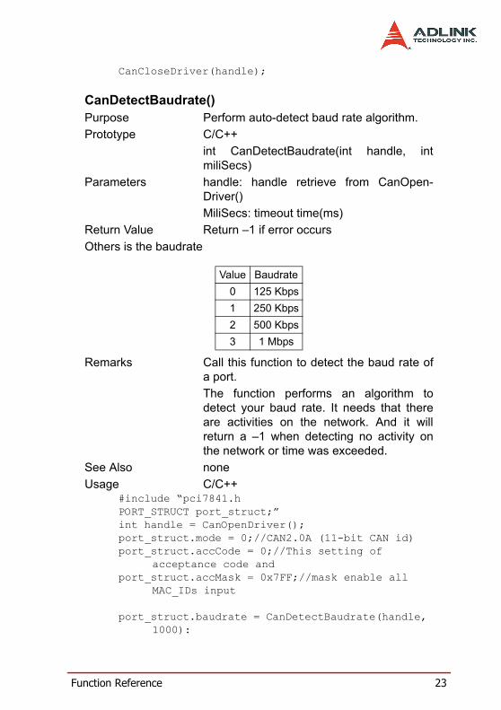
Return Value Return –1 if error occursOthers is the baudrate
Remarks Call this function to detect the baud rate ofa port. The function performs an algorithm todetect your baud rate. It needs that thereare activities on the network. And it willreturn a –1 when detecting no activity onthe network or time was exceeded.
See Also noneUsage C/C++
#include “pci7841.hPORT_STRUCT port_struct;”int handle = CanOpenDriver();port_struct.mode = 0;//CAN2.0A (11-bit CAN id)port_struct.accCode = 0;//This setting of
acceptance code and port_struct.accMask = 0x7FF;//mask enable all
MAC_IDs input port_struct.baudrate = CanDetectBaudrate(handle,
1000):
Value Baudrate0 125 Kbps1 250 Kbps2 500 Kbps3 1 Mbps

24 Function Reference
CanConfigPort(handle, &port_struct);CanCloseDriver(handle);
Visual Basic(Windows 95/98/NT)
CanRead()Purpose Direct read the register of PCI-7841.Prototype C/C++
BYTE CanRead(int handle, int offset)Parameters handle : handle retrieve from CanOpen-
Driver()offset : offset of register
Return Value Return data read from port.Remarks Direct read the register of PCI-7841.See Also CanWrite()Usage none
CanWrite()Purpose Direct write the register of PCI-7841.Prototype C/C++
void CanWrite(int handle, int offset, BYTEdata)
Parameters handle : handle retrieve from CanOpen-Driver()Offset : offset of registerdata : data write to the port
Return Value noneRemarks Call this function to directly write a register
of PCI-7841See Also CanRead()Usage none
CAN-layer I/O Functions
CanEnableReceive()Purpose Enable receive of a CAN port.Prototype C/C++

Function Reference 25
void CanEnableReceive(int handle);Parameters handle : handle retrieve from CanOpen-
Driver()Return Value noneRemarks Call this function to enable receive.
Any packet on the network that can inducea interrupt on your computer. If that packetcan pass your acceptance code and accep-tance mask setting. So if your programdoesn’t want to be disturbed. You can callCanDisableReceive() to disable receiveand CanEnableReceive() to enablereceives.
See Also CanDisableReceive()Usage none
CanDisableReceive()Purpose Disable receive of a CAN port.Prototype C/C++
void CanEnableReceive(int handle);Parameters handle : handle retrieve from CanOpen-
Driver()Return Value noneRemarks Please refer the CanEnableReceive()See Also CanEnableReceive()Usage none
CanSendMsg()Purpose Send can packet to a portPrototype C/C++
int CanSendMsg(int handle, CAN_PACKET*packet);
Parameters handle : handle retrieve from CanOpen-Driver()Packet : CAN_PACKET data
Return Value Return 0 is successful
26 Function Reference
-1 if error occursRemarks Send a message to an opened CAN port.
Actually, this function copies the data to thesending queue. Error occurs when the porthas not been opened yet or the packet is aNULL pointer. You can use the Error andEvent handling functions to handle theexceptions.
See Also CanRcvMsg()Usage C/C++
#include “pci7841.hPORT_STRUCT port_struct;CAN_PACKET sndPacket, rcvPacket;int handle = CanOpenDriver(0, 0);//open the port
0 of card 0CanConfigPort(handle, &port_struct);CanSendMsg(handle, &sndPacket);if(CanRcvMsg(handle, &rcvPacket) == 0){}CanCloseDriver(handle);
CanRcvMsg()Purpose Receive a can packet from a portPrototype C/C++
int CanSendMsg(int handle, CAN_PACKET*packet);
Parameters handle : handle retrieve from CanOpen-Driver()Packet : CAN_PACKET data
Return Value Return 0 is successful-1 if error occurs
Remarks Receive a message from an opened CANport.There are only 64-bytes FIFO under hard-ware. It can store from 3 to 21 packets. Sothere are memory buffer under driver. Whendata comes, the driver would move it from

Function Reference 27
card to memory. It starts after your port con-figuration is done. This function copies thebuffer to your application. So if your pro-gram has the critical section to process thedata on the network. We suggest that youcan call the CanClearBuffer() to clear thebuffer first. Error would be happened mostunder the following conditions:1. You want to access a port that has not beopened.2. Your packet is a NULL pointer.3. The receive buffer is empty.You can use the Status handling functionsto handle the exceptions.
See Also CanSendMsg()Usage See the CanSendMsg()
CAN-layer Status Functions
CanClearOverrun()Purpose Clear data overrun statusPrototype C/C++
void CanClearOverrun(int handle)Parameters handle : handle retrieve from CanOpen-
Driver()Return Value noneRemarks Clear the data overrun status
Sometimes if your system has heavy load,and the bus is busy. The data overrunwould be signalled. A Data Overrun signals,that data are lost, possibly causing incon-sistencies in the system.
See Also CanRcvMsg()Usage C/C++
#include “pci7841.hint handle = CanOpenDriver(0, 0);//open the port
0 of card 0

28 Function Reference
….CanClearOverrun(handle);CanCloseDriver(handle);
CanClearRxBuffer()Purpose Clear data in the receive bufferPrototype C/C++
void CanClearRxBuffer(int handle)Parameters handle : handle retrieve from CanOpen-
Driver()Return Value noneRemarks Clear the data in the receive buffer
There are 2-type of buffer defined in thedriver. First one is the FIFO in the card, thesecond one is the memory space inside thedriver. Both of them would be cleared afterusing this function.
See Also CanRcvMsg()Usage C/C++
#include “pci7841.hint handle = CanOpenDriver(0, 0);//open the port
0 of card 0….CanClearRxBuffer(handle);CanCloseDriver(handle);
CanClearTxBuffer()Purpose Clear Transmit BufferPrototype C/C++
void CanClearTxBuffer(int handle)Parameters handle : handle retrieve from CanOpen-
Driver()Return Value noneRemarks Clear the data in the transmit buffer.
Under a busy DeviceNet Network, yourtransmit request may not be done due tothe busy in the network. The hardware willsend it automatically when bus is free. The
Function Reference 29
un-send message would be stored in thememory of the driver. The sequence of out-going message is the FIRST-IN-FIRST-OUT. According this algorithm, if your pro-gram need to send an emergency data, youcan clear the transmit buffer and send itagain.
See Also CanRcvMsg()Usage C/C++
#include “pci7841.hint handle = CanOpenDriver(0, 0);//open the port
0 of card 0….CanClearTxBuffer(handle);CanCloseDriver(handle);
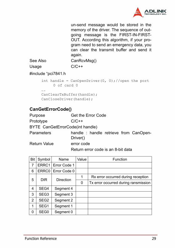
CanGetErrorCode()Purpose Get the Error CodePrototype C/C++BYTE CanGetErrorCode(int handle)Parameters handle : handle retrieve from CanOpen-
Driver()Return Value error code
Return error code is an 8-bit data
Bit Symbol Name Value Function7 ERRC1 Error Code 16 ERRC0 Error Code 0
5 DIR Direction1 Rx error occurred during reception0 Tx error occurred during ransmission
4 SEG4 Segment 43 SEG3 Segment 32 SEG2 Segment 21 SEG1 Segment 10 SEG0 Segment 0

30 Function Reference
Bit interpretation of ERRC1 and ERRC2
Bit interpretation of SEG4 to SEG 0
Bit ERRC1 Bit ERRC2 Function0 0 bit error0 1 form error1 0 stuff error1 1 other type of error
SEG4 SEG3 SEG2 SEG1 SEG0 Function0 0 0 1 1 start of frame0 0 0 1 0 ID.28 to ID.210 0 1 1 0 ID.20 to ID.180 0 1 0 0 bit SRTR0 0 1 0 1 bit IDE0 0 1 1 1 ID.17 to ID.130 1 1 1 1 ID.12 to ID.50 1 1 1 0 ID.4 to ID.00 1 1 0 0 RTR bit0 1 1 0 1 reserved bit 10 1 0 0 1 reserved bit 00 1 0 1 1 Data length code0 1 0 1 0 Data field0 1 0 0 0 CRC sequence1 1 0 0 0 CRC delimiter1 1 0 0 1 acknowledge slot1 1 0 1 0 end of frame1 0 0 1 0 intermission1 0 0 0 1 active error flag1 0 1 1 0 passive error flag1 0 0 1 1 tolerate dominant bits1 0 1 1 1 error delimiter1 1 1 0 0 overload flag
Function Reference 31
Remarks Get the information about the type andlocation of errors on the bus.When a bus error occurs, if your programinstalled the call-back function or error-han-dling event. The error-bit position would becaptured into the card. The value would befixed in the card until your program read itback.
See Also CanGetErrorWarningLimit(),CanSetErrorWarningLimit()
Usage C/C++#include “pci7841.hint handle = CanOpenDriver(0, 0);//open the port
0 of card 0….BYTE data = CanGetErrorCode();CanCloseDriver(handle);
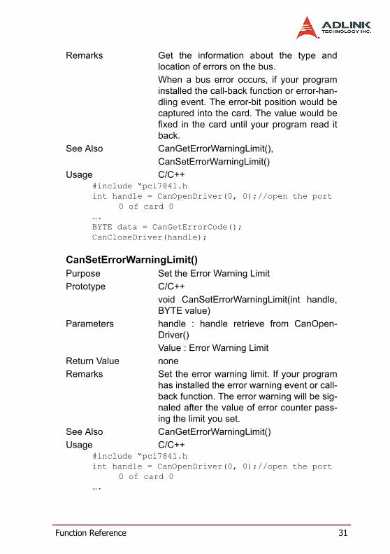
CanSetErrorWarningLimit()Purpose Set the Error Warning LimitPrototype C/C++
void CanSetErrorWarningLimit(int handle,BYTE value)
Parameters handle : handle retrieve from CanOpen-Driver()Value : Error Warning Limit
Return Value noneRemarks Set the error warning limit. If your program
has installed the error warning event or call-back function. The error warning will be sig-naled after the value of error counter pass-ing the limit you set.
See Also CanGetErrorWarningLimit()Usage C/C++
#include “pci7841.hint handle = CanOpenDriver(0, 0);//open the port
0 of card 0….

32 Function Reference
CanSetErrorWarning(handle, 96);CanCloseDriver(handle);
CanGetErrorWarningLimit()Purpose Get the Error Warning LimitPrototype C/C++
BYTE CanGetErrorWarningLimit(int han-dle)Visual Basic(Windows 95/98/NT)
Parameters handle : handle retrieve from CanOpen-Driver()
Return Value 0-255 (Error warning limit value)Remarks Get the error warning limitSee Also CanSetErrorWarningLimit()Usage C/C++
#include “pci7841.hint handle = CanOpenDriver(0, 0);//open the port
0 of card 0….BYTE limit = CanClearOverrun(handle);CanCloseDriver(handle);
CanGetRxErrorCount()Purpose Get the current value of the receive error
counterPrototype C/C++
BYTE CanGetRxErrorCount(int handle)Parameters handle : handle retrieve from CanOpen-
Driver()Return Value valueRemarks This function reflects the current of the
receive error counter. After hardware resethappened, the value returned would be ini-tialized to 0. If a bus-off event occurs, thereturned value would be 0.
See Also CanRcvMsg()Usage C/C++

Function Reference 33
#include “pci7841.hint handle = CanOpenDriver(0, 0);//open the port
0 of card 0….BYTE error_count = CanGetRxErrorCount();CanCloseDriver(handle);
CanGetTxErrorCount()Purpose Get the current value of the transmit error
counterPrototype C/C++
BYTE CanGetTxErrorCount(int handle)Parameters handle : handle retrieve from CanOpen-
Driver()Return Value valueRemarks This function reflects the current of the
transmit error counter. After hardware resethappened, the value would set to 127. Abus-off event occurs when the valuereaches 255. You can call the CanSetTxEr-rorCount() to set the value from 0 to 254 toclear the bus-off event.
See Also CanRcvMsg()Usage C/C++
#include “pci7841.hint handle = CanOpenDriver(0, 0);//open the port
0 of card 0….BYTE error_count = CanGetTxErrorCount(handle);CanCloseDriver(handle);
CanSetTxErrorCount()Purpose Set the current value of the transmit error
counterPrototype C/C++
void CanSetTxErrorCount(int handle, BYTEvalue)

34 Function Reference
Parameters handle : handle retrieve from CanOpen-Driver()value : a byte value
Return Value NoneRemarks This function set the current of the transmit
error counter.Please see the remark of CanGetTxError-Count().
See Also CanRcvMsg()Usage C/C++
#include “pci7841.hint handle = CanOpenDriver(0, 0);//open the port
0 of card 0….CanSetTxErrorCount(handle, 0);CanCloseDriver(handle);
CanGetPortStatus()Purpose Get Port StatusPrototype C/C++
int CanGetPortStatus(int handle,PORT_STATUS *PortStatus)
Parameters handle : handle retrieve from CanOpen-Driver()PortStatus : Pointer of PORT_STATUSstructure
Return Value No Error: 0Error: -1
Remarks Get Port Status(See the structure define fordetailed description)
See AlsoUsage C/C++
#include “pci7841.hPORT_STATUS port_status;int handle = CanOpenDriver(0, 0);// open the port
0 of card 0CanGetPortStatus(&port_status);CanClearOverrun();

Function Reference 35
CanCloseDriver(handle);
CanGetLedStatus()Purpose Get the LED status of cPCI-7841 and PM-
7841Prototype C/C++
BYTE CanGetLedStatus (int card, intindex);
Parameters card : card number Index : index of LED
Return Value status of Led
Remarks Get the status of Led This function supports the cPCI-7841 andPM-7841.
See Also CanSetLEDStatus()Usage C/C++
#include “pci7841.hint handle = CanOpenDriver(0, 0);//open the port
0 of card 0….BYTE flag = CanGetLedStatus(0, 0);;CanCloseDriver(handle);
CanSetLedStatus()Purpose Set the Led Status of cPCI-7841Prototype C/C++
void CanSetLedStatus(int card, int index,int flashMode);
Parameters card : card numberIndex : index of Led
flashMode :
Value Function0 Led Off1 Led On
Value Function

36 Function Reference
Return Value noneRemarks Set Led status of cPCI-7841 and PM-7841
This function supports the cPCI-7841 andPM-7841
See Also CanRcvMsg()Usage C/C++
#include “pci7841.hint handle = CanOpenDriver(0, 0);//open the port
0 of card 0….CanSetLedStatus(0, 0, 2);//Set Led to flashCanCloseDriver(handle);
CanGetRcvCnt()Purpose Get the how many message in the FIFOPrototype C/C++
int _stdcall CanGetRcvCnt(int handle)Parameters handle : handle retrieve from CanOpen-
Driver()Return Value value indicates the left unread messages in
the FIFO.Remarks Get the unread message count in the FIFO.
Because the interrupt would be very busywhile CAN bus is busy. There is possibilityto lost the event in Windows system. A wayto solve to this problem is to call this func-tion at free time while program running. Youalso can call this function to make sure thatreceiving FIFO is empty.
See Also CanGetReceiveEvent()Usage C/C++
#include “pci7841.hint handle = CanOpenDriver(0, 0);//open the port
0 of card 0…..int count = CanGetRcvCnt(handle);.
0 Led Off1 Led On
Function Reference 37
Error and Event Handling FunctionsWhen the exception occurs, your program may need to take somealgorithm to recover the problem. The following functions are oper-ation-system depended functions. You should care about therestriction in the operation-system.
DOS Environment
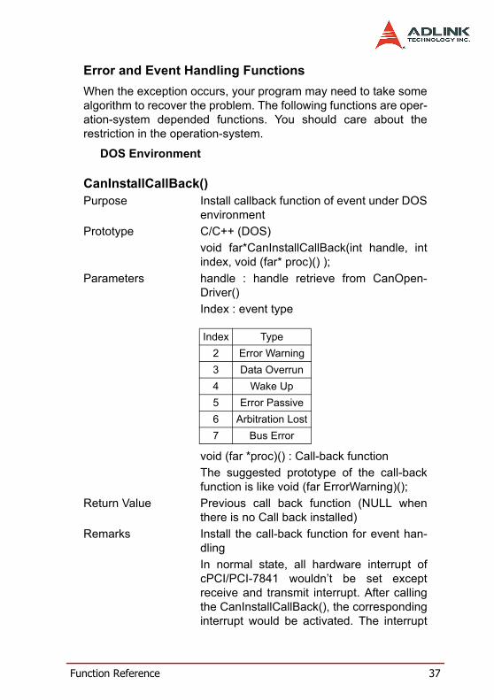
CanInstallCallBack()Purpose Install callback function of event under DOS
environmentPrototype C/C++ (DOS)
void far*CanInstallCallBack(int handle, intindex, void (far* proc)() );
Parameters handle : handle retrieve from CanOpen-Driver()Index : event type
void (far *proc)() : Call-back functionThe suggested prototype of the call-backfunction is like void (far ErrorWarning)();
Return Value Previous call back function (NULL whenthere is no Call back installed)
Remarks Install the call-back function for event han-dlingIn normal state, all hardware interrupt ofcPCI/PCI-7841 wouldn’t be set exceptreceive and transmit interrupt. After callingthe CanInstallCallBack(), the correspondinginterrupt would be activated. The interrupt
Index Type2 Error Warning3 Data Overrun4 Wake Up5 Error Passive6 Arbitration Lost7 Bus Error

38 Function Reference
occurs when the event happened. It will notbe disabled until using CanRemoveCall-Back() or a hardware reset.Actually, the call-back function is a part ofISR. You need to care about the DOS reen-trance problem, and returns as soon aspossible to preventing the lost of data.
See Also CanRemoveCallBack()Usage C/C++(DOS)
#include “pci7841.hvoid (far ErrorWarning)();int handle = CanOpenDriver(0, 0);// open the port 0 of card 0…// Installs the ErrorWarning handling event and
stores the previous one.void (far *backup) = CanInstallCallBack(0, 2,
ErrorWarning);CanRemoveCallBack(0, 2, NULL);//Remove the call-
back functionCanCloseDriver(handle);
CanRemoveCallBack()Purpose Remove the callback function of event
under DOS environmentPrototype C/C++(DOS)
int CanRemoveCallBack(int handle, intindex, void (far* proc)() );
Parameters handle : handle retrieve from CanOpen-Driver()Index : event type
Index Type2 Error Warning3 Data Overrun4 Wake Up5 Error Passive6 Arbitration Lost

Function Reference 39
void (far *proc)() : Previous call-back func-tion
Return Value Return 0 is successful-1 if error occurs
Remarks Install the call-back function for event han-dlingIn normal state, all hardware interrupt ofcPCI/PCI-7841 wouldn’t be set exceptreceive and transmit interrupt. After callingthe CanInstallCallBack(), the correspondinginterrupt would be activated. The interruptoccurs when the event happened. It will notbe disabled until using CanRemoveCall-Back() or a hardware reset.Actually, the call-back function is a part ofISR. You need to care about the DOS reen-trance problem, and returns as soon aspossible to preventing the lost of data.
See Also CanRemoveCallBack()Usage C/C++ (DOS)
#include “pci7841.hvoid (far ErrorWarning)();int handle = CanOpenDriver(0, 0);//open the port
0 of card 0…// Installs the ErrorWarning handling event and
stores the previous one.void (far *backup) = CanInstallCallBack(0, 2,
ErrorWarning);CanRemoveCallBack(0, 2, NULL);//Remove the call-
back function
7 Bus Error

40 Function Reference
CanCloseDriver(handle);Windows 95/98 Environment
CanGetReceiveEvent()Purpose Install the event under Windows 95/98/NT
systemPrototype C/C++ (Windows 95/98/NT)
void CanGetReceiveEvent(int handle,HANDLE *hevent);
Parameters handle : handle retrieve from CanOpen-Driver()Heven : HANDLE point for receive event
Return Value none Remarks Retrieve receive notify event
Under Windows 95/98/NT environment,your program can wait the input messageby waiting an event. You can refer to follow-ing program to use this function. But theCAN system is a heavy-load system. Underthe full speed(of course, it depends on yoursystem), the hardware receives the mes-sage faster than the event occurs. Underthis condition, the event could be combinedby OS. So the total count of event may beless than actually receive. You can call theCanGetRcvCnt() to retrieve the unreadmessage in the driver’s FIFO.
See Also CanGetRcvCnt()Usage C/C++ (Windows 95/98/NT)
#include “pci7841.hHANDLE recvEvent0;
int handle = CanOpenDriver(0, 0);// open the port 0 of card 0int count1;CanGetReceiveEvent(handle, rcvEvent0);if(WaitForSingleObject(rcvEvent0, INFINITE) == WAIT_OBJECT_0){

Function Reference 41
// You need not to call ResetEvent()…..err=CanRcvMsg(handle,&rcvMsg[0][rcvPatterns[0]]);rcvPatterns[0]++;}cout1 = CanGetRcvCnt(handle[0]);// To retrieve number of unread // in the FIFO
CanInstallEvent()Purpose Install the event under Windows 95/98/NT
systemPrototype C/C++ (Windows 95/98/NT)
int CanInstallEvent(int handle, int index,HANDLE hEvent);
Parameters handle : handle retrieve from CanOpen-Driver()Index : event type
HEvent : HANDLE created from Cre-ateEvent()(Win32 SDK)
Return Value Return 0 is successful-1 if error occurs
Remarks Install the notify eventUnlike the Dos environment, there is onlyone error handling function under Windows95/98/NT environment. First you need tocreate an event object, and send it to theDLL. The DLL would make a registry in thekernel and pass it to the VxD(SYS in NT
Index Type2 Error Warning3 Data Overrun4 Wake Up5 Error Passive6 Arbitration Lost7 Bus Error

42 Function Reference
system). You can’t release the event objectyou created, because it was attached to theVxD. The VxD would release the eventobject when you installed another event.One way to disable the event handling isthat you install another event which handleis NULL (ex: CanInstallEvent(handle, index,NULL)). And you can create a thread tohandle the error event.
See Also CanRemoveCallBack(),CanInstallCall-Back()
Usage C/C++ (Windows 95/98/NT)#include “pci7841.hint handle = CanOpenDriver(0, 0);// open the port 0 of card 0…// Installs the ErrorWarning handling event and
stores the previous one.HANDLE hEvent = CreateEvent(NULL, FALSE, TRUE,
“ErrorWarning”);CanInstallEvent(0, 2, hEvent);//..create a thread ….
Thread functionWaitForSingleObject(hEvent, INFINITE);
ResetEvent(hEvent);// Event handling

Warranty Policy 43
Warranty PolicyThank you for choosing ADLINK. To understand your rights andenjoy all the after-sales services we offer, please read the follow-ing carefully.
1. Before using ADLINK’s products please read the user man-ual and follow the instructions exactly. When sending indamaged products for repair, please attach an RMA appli-cation form which can be downloaded from: http://rma.adlinktech.com/policy/.
2. All ADLINK products come with a limited two-year war-ranty, one year for products bought in China:
The warranty period starts on the day the product is shipped from ADLINK’s factory.Peripherals and third-party products not manufactured by ADLINK will be covered by the original manufactur-ers' warranty. For products containing storage devices (hard drives, flash cards, etc.), please back up your data before send-ing them for repair. ADLINK is not responsible for any loss of data. Please ensure the use of properly licensed software with our systems. ADLINK does not condone the use of pirated software and will not service systems using such software. ADLINK will not be held legally responsible for products shipped with unlicensed software installed by the user. For general repairs, please do not include peripheral accessories. If peripherals need to be included, be cer-tain to specify which items you sent on the RMA Request & Confirmation Form. ADLINK is not responsible for items not listed on the RMA Request & Confirmation Form.

44 Warranty Policy
3. Our repair service is not covered by ADLINK's guaranteein the following situations:
Damage caused by not following instructions in the User's Manual.Damage caused by carelessness on the user's part dur-ing product transportation. Damage caused by fire, earthquakes, floods, lightening, pollution, other acts of God, and/or incorrect usage of voltage transformers.Damage caused by unsuitable storage environments (i.e. high temperatures, high humidity, or volatile chemi-cals).Damage caused by leakage of battery fluid during or after change of batteries by customer/user. Damage from improper repair by unauthorized ADLINK technicians. Products with altered and/or damaged serial numbers are not entitled to our service. This warranty is not transferable or extendible.Other categories not protected under our warranty.
4. Customers are responsible for shipping costs to transportdamaged products to our company or sales office.
5. To ensure the speed and quality of product repair, pleasedownload an RMA application form from our company web-site: http://rma.adlinktech.com/policy. Damaged productswith attached RMA forms receive priority.
If you have any further questions, please email our FAE staff: [email protected].