Embed Size (px)
Citation preview

ByVac Product Specification
Dual Interface LCD Display Controller BV4618
©ByVac Page 1 of 13
BV4618 Dual Interface LCD Display & Keypad ControllerProduct specification Nov 2009 V0.a

ByVac Product Specification
Dual Interface LCD Display Controller BV4618
©ByVac Page 2 of 13
Contents 1. Introduction................................................................................................................ 3
2. Features..................................................................................................................... 3
3. Physical Specification ................................................................................................... 3
3.1. LCD ....................................................................................................................... 3
3.2. Keypad .................................................................................................................. 4
3.3. Serial Interface ....................................................................................................... 4
3.4. I2C........................................................................................................................ 5
4. Reset & Interface Detect .............................................................................................. 5
4.1. I2C........................................................................................................................ 5
4.2. RS232 ................................................................................................................... 5
4.3. Serial..................................................................................................................... 6
5. Automatic Baud Rate ................................................................................................... 6
6. Hardware Reset........................................................................................................... 6
7. VT100........................................................................................................................ 6
8. I2C............................................................................................................................ 6
8.1. Writing................................................................................................................... 6
8.1.1. Reading ............................................................................................................. 6
9. Custom Characters ...................................................................................................... 7
9.1. Implemented Escape Codes & I2C commands............................................................. 8
ByVac Product Specification
Dual Interface LCD Display Controller BV4618
©ByVac Page 3 of 13
Rev Change
Oct 2010
Preliminary
Nov. 2010
Version 1.1 I2C updated to remove timing issues.
Jen 2011
Added picture Factory reset
Jan 20th
2011 Error in command table esc[<num>d for autoLF. Version 1.2 released (scrolling)
Mar 2011
Updates i2c cursor on/off instructions
Jun 2011
Minor revision
July 2011
Added pin out for alternative LCD connector
Nov 2011
Version 1.3 allows custom message, updated command <esc>c instruction
Apr 2012
Version 1.4 improved custom characters with serial interface
Jun 2012
Added delay timing information to command table
Jul 2013 Firmware update 1.7
Nov 2013
Updated custom characters
1. Introduction The BV4618 is a dual interface LCD display and keypad controller intended for the text display modules using the HD44780 or similar controller. These are most popular in 16x2, 20x4 and 20x2 formats. This controller will handle 1 to 4 lines and up to 40 characters or any combination of those. The default is 16x2 and the user sets the number of lines and characters as required.
Once a serial interface is established anything entered will be echoed to the display, by default the characters will wrap to the next line.
Further information on how to use the device is in the user guide.
2. Features Serial Input and I2C input Automatic Baud rate from a selection
of rates up to 112500 Serial interface accepts RS232 input
voltage levels I2C up to 400KHz VT100 superset Fully scrolling 65 byte input buffer
16 byte keypad buffer Max line length 80 char Max Lines 4 keypad up to 16 switches (4x4) Supply voltage 5V DC Current: 6mA @ 4.7V Size: 55mm x 24mm
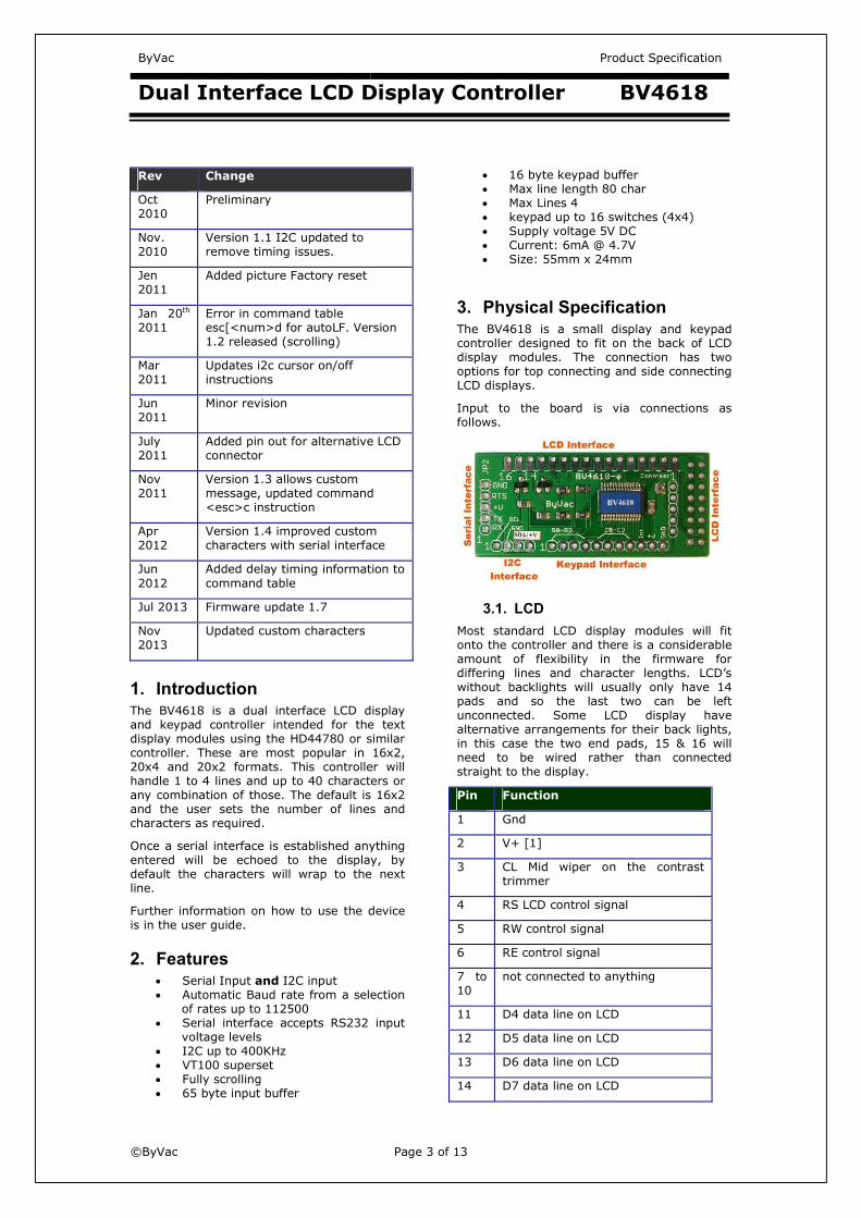
3. Physical Specification The BV4618 is a small display and keypad controller designed to fit on the back of LCD display modules. The connection has two options for top connecting and side connecting LCD displays.
Input to the board is via connections as follows.
3.1. LCD Most standard LCD display modules will fit onto the controller and there is a considerable amount of flexibility in the firmware for differing lines and character lengths. LCD’s without backlights will usually only have 14 pads and so the last two can be left unconnected. Some LCD display have alternative arrangements for their back lights, in this case the two end pads, 15 & 16 will need to be wired rather than connected straight to the display.
Pin Function
1 Gnd
2 V+ [1]
3 CL Mid wiper on the contrast trimmer
4 RS LCD control signal
5 RW control signal
6 RE control signal
7 to 10
not connected to anything
11 D4 data line on LCD
12 D5 data line on LCD
13 D6 data line on LCD
14 D7 data line on LCD
ByVac Product Specification
Dual Interface LCD Display Controller BV4618
©ByVac Page 4 of 13
15 LCD + [2]
16 Gnd
LCD Connector
[1] Take care that the V+ and GND connections match the display you have, most do but there are a few that have them the other way round.
[2] Very occasionally some LCD back lights are either not on this connector or are the other way round. In this case straight pins cannot be used and these must be wired.
15 16
13 14
11 12
9 10
7 8
5 6
3 4
1 2
LCD connector to right hand side
The connector is pin for pin connected to the top LCD connector with the pin numbers as above. This is looking from the component side.
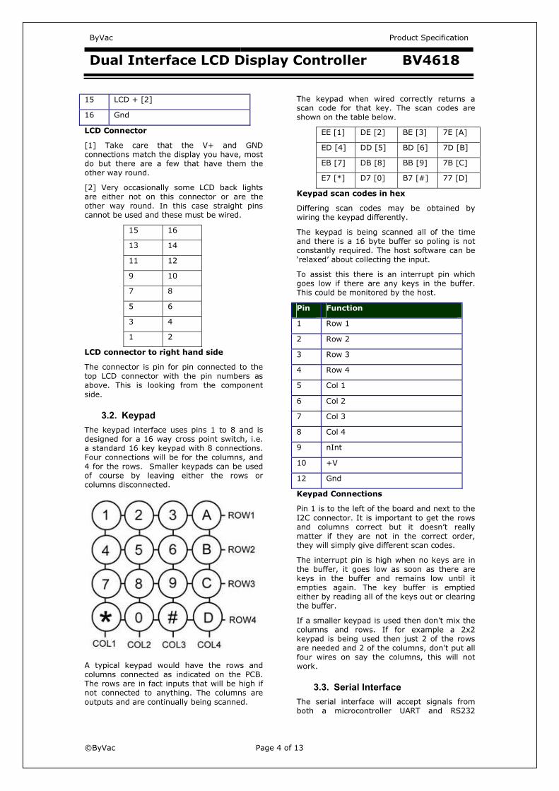
3.2. Keypad The keypad interface uses pins 1 to 8 and is designed for a 16 way cross point switch, i.e. a standard 16 key keypad with 8 connections. Four connections will be for the columns, and 4 for the rows. Smaller keypads can be used of course by leaving either the rows or columns disconnected.
A typical keypad would have the rows and columns connected as indicated on the PCB. The rows are in fact inputs that will be high if not connected to anything. The columns are outputs and are continually being scanned.
The keypad when wired correctly returns a scan code for that key. The scan codes are shown on the table below.
EE [1] DE [2] BE [3] 7E [A]
ED [4] DD [5] BD [6] 7D [B]
EB [7] DB [8] BB [9] 7B [C]
E7 [*] D7 [0] B7 [#] 77 [D]
Keypad scan codes in hex
Differing scan codes may be obtained by wiring the keypad differently.
The keypad is being scanned all of the time and there is a 16 byte buffer so poling is not constantly required. The host software can be ‘relaxed’ about collecting the input.
To assist this there is an interrupt pin which goes low if there are any keys in the buffer. This could be monitored by the host.
Pin Function
1 Row 1
2 Row 2
3 Row 3
4 Row 4
5 Col 1
6 Col 2
7 Col 3
8 Col 4
9 nInt
10 +V
12 Gnd
Keypad Connections
Pin 1 is to the left of the board and next to the I2C connector. It is important to get the rows and columns correct but it doesn’t really matter if they are not in the correct order, they will simply give different scan codes.
The interrupt pin is high when no keys are in the buffer, it goes low as soon as there are keys in the buffer and remains low until it empties again. The key buffer is emptied either by reading all of the keys out or clearing the buffer.
If a smaller keypad is used then don’t mix the columns and rows. If for example a 2x2 keypad is being used then just 2 of the rows are needed and 2 of the columns, don’t put all four wires on say the columns, this will not work.
3.3. Serial Interface The serial interface will accept signals from both a microcontroller UART and RS232
ByVac Product Specification
Dual Interface LCD Display Controller BV4618
©ByVac Page 5 of 13
voltage levels. The connector is to the side and has the following pins.
Pin Function
5 GND
4 RX (RS232)
3 +V
2 TX
1 RX
BV4618
GND
+V
TX/RX
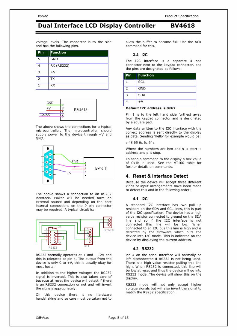
The above shows the connections for a typical microcontroller. The microcontroller should supply power to the device through +V and GND.
The above shows a connection to an RS232 interface. Power will be needed form an external source and depending on the host internal connections on the 9 pin connector may be required. A typical circuit is:
RS232 normally operates at + and – 12V and this is tolerated at pin 4. The output from the device is only 0 to +V, this is usually okay for most hosts.
In addition to the higher voltages the RS232 signal is inverted. This is also taken care of because at reset the device will detect if there is an RS232 connection or not and will invert the signals appropriately.
On this device there is no hardware handshaking and so care must be taken not to
allow the buffer to become full. Use the ACK command for this.
3.4. I2C The I2C interface is a separate 4 pad connector next to the keypad connector. and the pins are designated as follows:
Pin Function
1 SCL
2 GND
3 SDA
4 +V
Default I2C address is 0x62
Pin 1 is to the left hand side furthest away from the keypad connector and is designated by a square pad.
Any data written to the I2C interface with the correct address is sent directly to the display as data. Sending ‘Hello’ for example would be:
s 48 65 6c 6c 6f s
Where the numbers are hex and s is start + address and p is stop.
To send a command to the display a hex value of 0x1b is used. See the VT100 table for further details on commands.
4. Reset & Interface Detect Because the device will accept three different kinds of input arrangements have been made to detect this and in the following order:
4.1. I2C A standard I2C interface has two pull up resistors on the SDA and SCL lines, this is part of the I2C specification. The device has a high value resistor connected to ground on the SDA line and so if the I2C interface is not connected this line will be low. When connected to an I2C bus this line is high and is detected by the firmware which puts the device into I2C mode. This is indicated on the device by displaying the current address.
4.2. RS232 Pin 4 on the serial interface will normally be left disconnected if RS232 is not being used. There is a high value resistor pulling this line high. When RS232 is connected, this line will be low at reset and thus the device will go into RS232 mode. The device will show this on the display.
RS232 mode will not only accept higher voltage signals but will also invert the signal to match the RS232 specification.

ByVac Product Specification
Dual Interface LCD Display Controller BV4618
©ByVac Page 6 of 13
4.3. Serial The serial mode will be entered at all other times.
5. Automatic Baud Rate This does not apply to I2C mode
When the display is first switched on or has been reset with the appropriate command, the FIRST byte that MUST be sent is a Carriage Return (enter on the keyboard) This is byte value 13 or 0x0d in hex. The device will be able to establish the Baud rate from this single byte. Until this happens the device cannot be used.
See command table for fixing the baud rate to a particular value.
The Baud rate is determined form the following standard rates and will select one of these based on that first byte:
9600, 14400, 19200, 38400, 57600, 115200
The transmitting terminal must be set at one of those rates.
6. Hardware Reset
The purpose of the hardware reset is to reset the EEPROM back to a known position so that the display will work correctly. The procedure is:
1) Disconnect the display from power
2) Connect the reset pins together, these are shown on the picture above in red.
3) Apply power
4) Disconnect power
The display will now be reset back to the factory defaults.
7. VT100 This applies to Serial and RS232 modes.
Once connected the display simply accepts text and duplicates it to the screen. Connecting a terminal emulator such as BV_Comm or HyperTerminal will enable anything typed into it to be duplicated on the display.
To control the display, for example clearing the screen or placing letters in a certain location escape codes are used. An escape code is the escape key (byte 27) followed by various symbols, numbers and letters.
Escape codes have been used for many years and were a feature of the early terminals. The most popular set of codes is called VT100 used by old DEC terminals. It was so popular that it became a standard way to control terminal screens before the days of the PC.
This display wherever possible uses the most common of these codes but also uses many other non-standard codes to enhance the operation.
8. I2C The default I2C address is:
8bit write 0x62 read 0x63
7bit 0x31
For an explanation of I2C addressing and trouble shooting see www.asi.byvac.com
8.1. Writing Any data send from the I2C interface is directed to the display and so will be shown on the display. To initiate a command the first data byte after the start condition and address should be 0x1b. This will tell the interface to expect a command.
As an example to move the cursor to row 2 column 3 the following I2C sequence would be used:
s 1b 24 2 3 p
Where s represents a start condition followed by the device write address (0x62), 1b is the command initiator, 24 is the move cursor command and 2,3 is the new cursor position. All numbers are in hex.
8.1.1. Reading Reading is slightly different in that, first a command is given as in the writing mode and then a read is performed using the device read address (0x63 in 8 bit addressing).
As an example, to read the number of keys in the keypad buffer, first the command is sent:
s 1b 10 p
This will place a byte* in the I2C buffer which has a value of the number of keys in the keypad buffer.
To read this:
ByVac Product Specification
Dual Interface LCD Display Controller BV4618
©ByVac Page 7 of 13
s-63 g-1 p
The above is using the notation from the BV4221, it means:
1) send start condition
2) send 0x63
3) read 1 byte
4) send stop condition
Normally the write and read would be carried out together and a re-start used.
*Clock stretching will be used if a data is not available at the time of reading, if this is not available by the master then use a short delay between the requesting command and reading command.
9. Custom Characters To create a custom character you have to initially write to the CGRAM, this is done by using the direct LCD command code (esc[<num>E) or the I2C equivalent. Then send bytes as data, as an example this is the pseudo code for creating an up arrow for character 0
send(esc[64E) // set write to CGRAM pos 0
send(esc[4e) ** see text
send(esc[10e)
send(esc[21e)
send(esc[4e)
send(esc[4e)
send(esc[4e)
send(esc[4e)
send(esc[4e)
send(esc[128E) *** see text
There will now be an up arrow character in position 0. To display it send(0). The character positions are as follows:
Character Base Address 0 64 1 72 2 80 3 88 4 96 5 104 6 112 7 120
** Sending 10 to the BV4618 would not actually get to the LCD. This is because it is the code for LF and this will be intercepted by the controller to move or scroll the display. To send 10 without interception the code is used as in the above. This will apply to 8,10,13 and 27. This command was added on Version 1.4
In this case all of the characters have been 'escaped' to be on the safe side.
*** The last send simply puts the CGRAM back to the start of line 1.

ByVac Product Specification
Dual Interface LCD Display Controller BV4618
©ByVac Page 8 of 13
9.1. Implemented Escape Codes & I2C commands S Column is the VT100 standard, Y is standard, P is partially standard, N is non-standard
Code is the escape commands that will invoke the action, data that does not start with escape (0x1b) will be sent to the display as is.
I2C is the I2C commands that will invoke the action, any I2C data that does not begin with 0x1b will be sent to the display as is. Not all commands are implemented in I2C, where this is, no I2C command is shown.
* indicates that this is the default action
S Code I2C Name Description
Y LF 0x1b 0xa Line feed (10) Moves the cursor down one line, if the cursor is on the last line then the command is ignored.
Y CR 0x1b 0xd Carriage return (13) Moves the cursor to the beginning of the current line Note this will also add line feed by default unless switch off – see the add line feed command.
I2C
I2C ignores add line feed
Y BS Back space (8) Moves the cursor back one space and deletes the character immediately to the left before moving the cursor.
Cursor Movements
Y esc[<n>A 0x1b x020 Move cursor up Moves the cursor to up, if the cursor has reached the top of the display the command is ignored. A number <n> can be optionally specified for move the cursor up that number of times. This does not apply to I2C which can only move one time.
Y esc[<n>B 0x1b x021 Move cursor down Moves the cursor to down, if the cursor has reached the top of the display the command is ignored. A number <n> can be optionally specified for move the cursor down that number of times. This does not apply to I2C which can only move one time.
Y esc[<n>C 0x1b x022 Move cursor right Moves the cursor to the right, if the cursor has reached the top of the display the command is ignored. A number <n> can be optionally specified for move the cursor right that number of times. This does not apply to I2C which can only move one time.
Y esc[<n>D 0x1b x023 Move cursor left Moves the cursor to the left, if the cursor has reached the top of the display the command is ignored. A number <n> can be optionally specified for move the cursor left that number of times. This does not apply to I2C which can only move one time.
ByVac Product Specification
Dual Interface LCD Display Controller BV4618
©ByVac Page 9 of 13
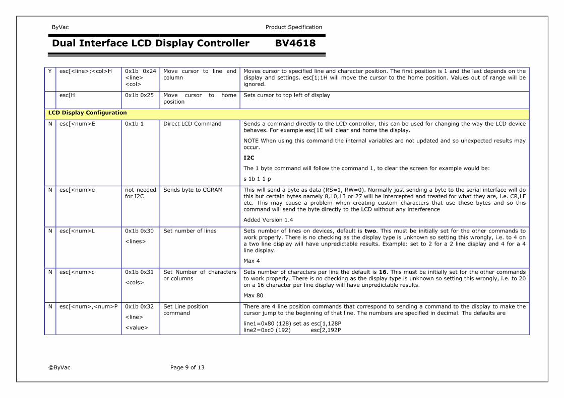
Y esc[<line>;<col>H 0x1b 0x24 <line> <col>
Move cursor to line and column
Moves cursor to specified line and character position. The first position is 1 and the last depends on the display and settings. esc[1;1H will move the cursor to the home position. Values out of range will be ignored.
esc[H 0x1b 0x25 Move cursor to home position
Sets cursor to top left of display
LCD Display Configuration
N esc[<num>E 0x1b 1 Direct LCD Command Sends a command directly to the LCD controller, this can be used for changing the way the LCD device behaves. For example esc[1E will clear and home the display.
NOTE When using this command the internal variables are not updated and so unexpected results may occur.
I2C
The 1 byte command will follow the command 1, to clear the screen for example would be:
s 1b 1 1 p
N esc[<num>e not needed for I2C
Sends byte to CGRAM This will send a byte as data (RS=1, RW=0). Normally just sending a byte to the serial interface will do this but certain bytes namely 8,10,13 or 27 will be intercepted and treated for what they are, i.e. CR,LF etc. This may cause a problem when creating custom characters that use these bytes and so this command will send the byte directly to the LCD without any interference
Added Version 1.4
N esc[<num>L 0x1b 0x30
<lines>
Set number of lines Sets number of lines on devices, default is two. This must be initially set for the other commands to work properly. There is no checking as the display type is unknown so setting this wrongly, i.e. to 4 on a two line display will have unpredictable results. Example: set to 2 for a 2 line display and 4 for a 4 line display.
Max 4
N esc[<num>c 0x1b 0x31
<cols>
Set Number of characters or columns
Sets number of characters per line the default is 16. This must be initially set for the other commands to work properly. There is no checking as the display type is unknown so setting this wrongly, i.e. to 20 on a 16 character per line display will have unpredictable results.
Max 80
N esc[<num>,<num>P 0x1b 0x32
<line>
<value>
Set Line position command
There are 4 line position commands that correspond to sending a command to the display to make the cursor jump to the beginning of that line. The numbers are specified in decimal. The defaults are
line1=0x80 (128) set as esc[1,128P line2=0xc0 (192) esc[2,192P
ByVac Product Specification
Dual Interface LCD Display Controller BV4618
©ByVac Page 10 of 13
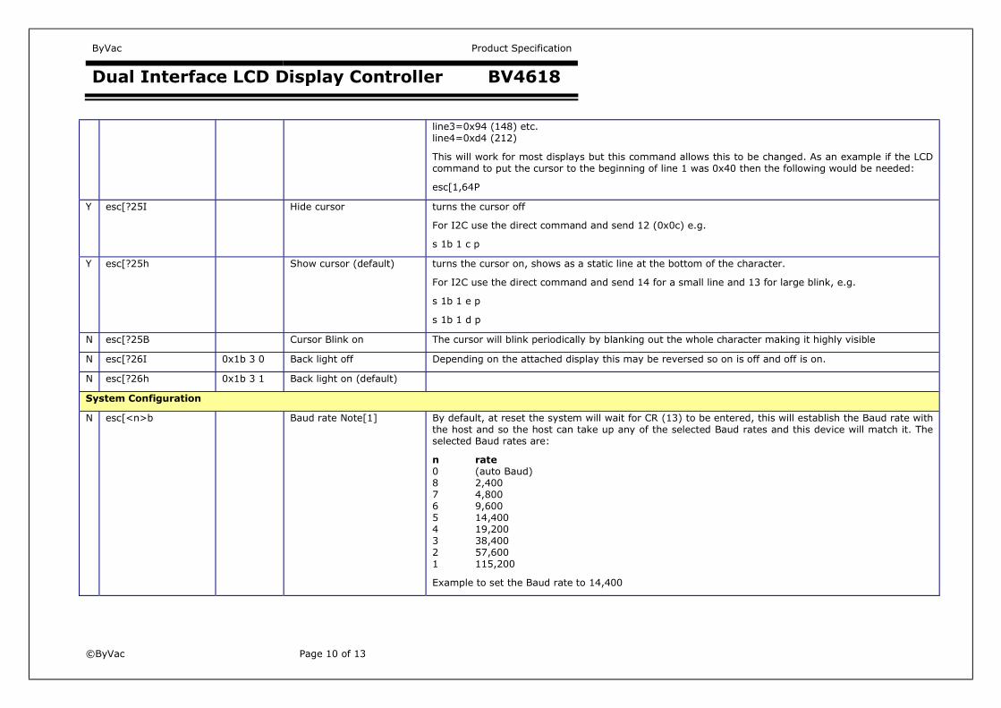
line3=0x94 (148) etc. line4=0xd4 (212)
This will work for most displays but this command allows this to be changed. As an example if the LCD command to put the cursor to the beginning of line 1 was 0x40 then the following would be needed:
esc[1,64P
Y esc[?25I Hide cursor turns the cursor off
For I2C use the direct command and send 12 (0x0c) e.g.
s 1b 1 c p
Y esc[?25h Show cursor (default) turns the cursor on, shows as a static line at the bottom of the character.
For I2C use the direct command and send 14 for a small line and 13 for large blink, e.g.
s 1b 1 e p
s 1b 1 d p
N esc[?25B Cursor Blink on The cursor will blink periodically by blanking out the whole character making it highly visible
N esc[?26I 0x1b 3 0 Back light off Depending on the attached display this may be reversed so on is off and off is on.
N esc[?26h 0x1b 3 1 Back light on (default)
System Configuration
N esc[<n>b Baud rate Note[1] By default, at reset the system will wait for CR (13) to be entered, this will establish the Baud rate with the host and so the host can take up any of the selected Baud rates and this device will match it. The selected Baud rates are:
n rate0 (auto Baud) 8 2,400 7 4,800 6 9,600 5 14,400 4 19,200 3 38,400 2 57,600 1 115,200
Example to set the Baud rate to 14,400

ByVac Product Specification
Dual Interface LCD Display Controller BV4618
©ByVac Page 11 of 13
esc[5b
The effect will take place after reset.
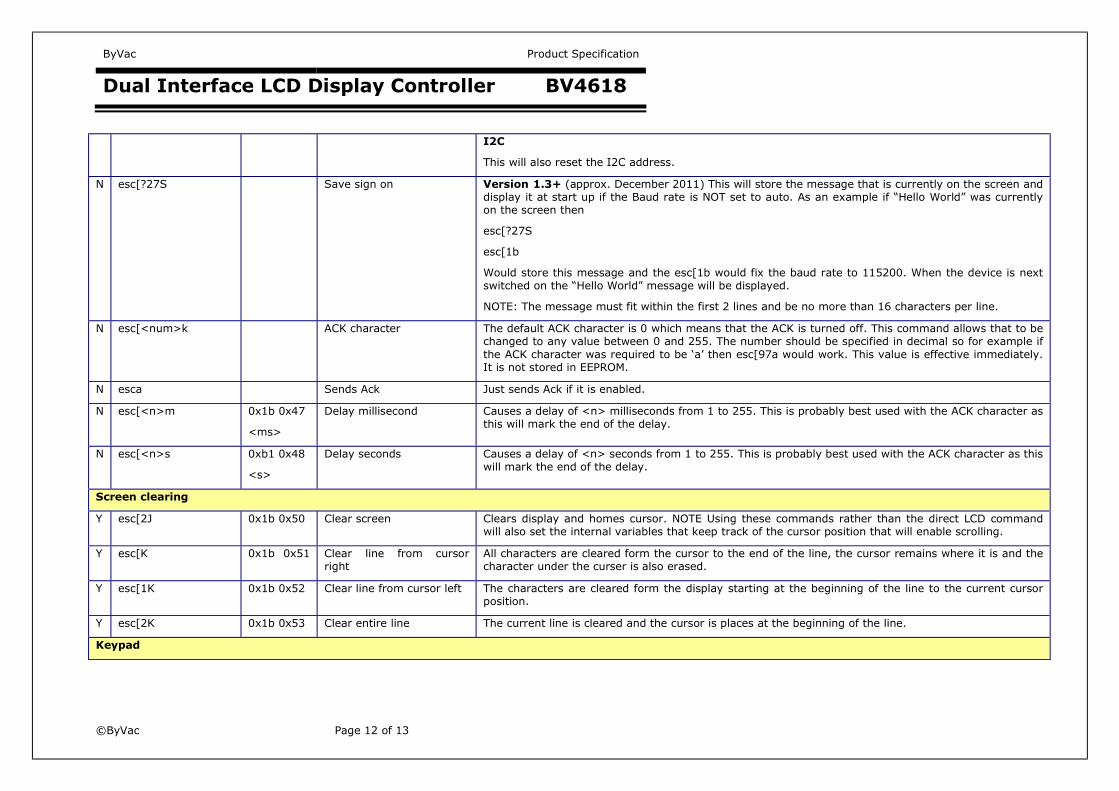
N esc[?31d 0x1b 0x40 Device ID Returns device ID as an integer number, the BV4618 has a device ID=4618
I2C
This will return a 16 bit number as 2 bytes.
N esc[?31f 0x1b 0x41 Firmware Version Returns a dotted number i.e. 0.7
I2C
Returns two bytes the high and then low version numbers, i.e. o and 7 in the above given example.
N esc[<n>d Add LF to CR (default) This command controls whether line feed is added to carriage return. In other words with this command set (1) when carriage return (13) is received the system will also add a line feed. This is the default and can be turned on or off with this command.
Example: to turn off this action esc[0r
N esc[<n>x 0x1b 0x45 <n>
Stop vertical scrolling
(default off)
By default this display will scroll when it reaches the last line. From feedback received this can be a problem as the first line will disappear (scroll) when the last character of the last line is reached. Setting this to 1 will turn off vertical scrolling and the cursor will jump to the top of the display instead.
to turn off scrolling: esc[1x (back on is esc[0x
I2C: s 1b 45 1 p
N esc[<n>a 0x1b 0x42 0x55 0x37 <address>
Set I2C Address
Note [1]
This is used to set the I2C address from its default value. The value is in decimal format and must be an even number as this is the 8 bit write address. Odd numbers will be rejected. The address is set while ever the device is powered and takes effect on the next reset. The address is written to the EEPROM so it is available at start up.
Example to set the address to 0x42: esc[66a
I2C Example: s 1b 42 55 35 42 p
N escc 0x1b 0x43 Reset Escape ‘c’ will reset the whole device. Please note, this is the same as esc[4J for version 1.2+
A delay of at least 500mS is required after reset, particularly when using I2C as if not the device may revert to Serial mode.
N esc[4J 0x1b 0x44 Reset EEPROM Resets EEPROM data back to factory settings. All user settings will be overwritten and the device will be back to how it was when leaving the factory. If the device is not responding to serial commands then a hardware factory reset will be required.
ByVac Product Specification
Dual Interface LCD Display Controller BV4618
©ByVac Page 12 of 13
I2C
This will also reset the I2C address.
N esc[?27S Save sign on Version 1.3+ (approx. December 2011) This will store the message that is currently on the screen and display it at start up if the Baud rate is NOT set to auto. As an example if “Hello World” was currently on the screen then
esc[?27S
esc[1b
Would store this message and the esc[1b would fix the baud rate to 115200. When the device is next switched on the “Hello World” message will be displayed.
NOTE: The message must fit within the first 2 lines and be no more than 16 characters per line.
N esc[<num>k ACK character The default ACK character is 0 which means that the ACK is turned off. This command allows that to be changed to any value between 0 and 255. The number should be specified in decimal so for example if the ACK character was required to be ‘a’ then esc[97a would work. This value is effective immediately. It is not stored in EEPROM.
N esca Sends Ack Just sends Ack if it is enabled.
N esc[<n>m 0x1b 0x47
<ms>
Delay millisecond Causes a delay of <n> milliseconds from 1 to 255. This is probably best used with the ACK character as this will mark the end of the delay.
N esc[<n>s 0xb1 0x48
<s>
Delay seconds Causes a delay of <n> seconds from 1 to 255. This is probably best used with the ACK character as this will mark the end of the delay.
Screen clearing
Y esc[2J 0x1b 0x50 Clear screen Clears display and homes cursor. NOTE Using these commands rather than the direct LCD command will also set the internal variables that keep track of the cursor position that will enable scrolling.
Y esc[K 0x1b 0x51 Clear line from cursor right
All characters are cleared form the cursor to the end of the line, the cursor remains where it is and the character under the curser is also erased.
Y esc[1K 0x1b 0x52 Clear line from cursor left The characters are cleared form the display starting at the beginning of the line to the current cursor position.
Y esc[2K 0x1b 0x53 Clear entire line The current line is cleared and the cursor is places at the beginning of the line.
Keypad

ByVac Product Specification
Dual Interface LCD Display Controller BV4618
©ByVac Page 13 of 13
N esc[n 0x1b 0x10 Returns number of keys in keypad buffer
Returns the number of keys in the keypad buffer as a decimal number and follows this by the ACK character.
I2C
Returns 1 byte
N esc[k 0x1b 0x11 Returns key scan code Returns the key scan code as a hex number, the code will depend on how the keypad has been wired. The code is followed by the ACK character. If no keys are in the buffer 0 is returned**. When a key is fetched it is removed from the buffer and so the total number of codes in the buffer is reduced by 1.
**NOTE This is ASCII coded so that the actual byte returned will be 0x30 or decimal 48
I2C
Returns 1 byte
N esc[c 0x1b 0x14 Clear keypad buffer The keypad buffer is reset to 0.
N esc[<num>r 0x1b 0x15
<num>
Keypad debounce This by default is set to 50 and is a function of how the device will be polled and how sensitive the keypad needs to be. The actual value should be found by trial and error but 50 is a good starting point. If when pressing a single key more then one key or a spurious is registered then increase the value. If when pressing a single key it takes a long time to register that key then reduce the value.
Notes
[1] Most values are kept in RAM and are lost after switch off, however there are some exceptions. The following values when set are immediately stored in EEPROM and will be retained after switch off. These should only be set once, they should not be set by the host each time the program is run.
Baud Rate Default Auto
I2C Address Default 0x62 (8 bit)