Embed Size (px)
Citation preview
DUAL BELLOWS
DIFFERENTIAL PRESSURE GAUGE
MODEL: LI-CYJ-1
User’s Manual
Version 1, Dec 2008
TMC Products Inc.
P O BOX 5005
Rancho Santa Fe,
CA 92067, U.S.A.
858-754-1101 (phone or fax)
www.tmcpi.com

LI-CYJ-1 Differential Pressure Gauge User’s manual
Copyright 2008 TMC Products Inc. Page 2
Contents
1.0 Introduction ............................................................................................................................................ 3
2.0 Design and operation .............................................................................................................................. 3
DPMU .................................................................................................................................................... 3
3.0 Placing the indicator in service ............................................................................................................... 7
4.0 Zero position adjustment ........................................................................................................................ 7
5.0 Parts diagram ........................................................................................................................................ 12
6.0 Technical specifications ........................................................................................................................ 14
7.0 Storage .................................................................................................................................................. 14
8.0 Service after sales ................................................................................................................................. 15
9.0 Warranty ............................................................................................................................................... 15
Disclaimer:........................................................................................................................................... 16
10.0 TMC small part number/ordering guide ............................................................................................. 16
LI-CYJ-1 Differential Pressure Gauge User’s manual
Copyright 2008 TMC Products Inc. Page 3
1.0 Introduction
The LI -CYJ-1 is a differential pressure indicator used to measure differential pressure of liquid
level or flow. Typical applications include the measurement of the level in Cryogenic tanks
holding liquid oxygen, liquid nitrogen, liquid carbon dioxide, liquid argon and similar liquefied
gases. In addition, the level of virtually any liquid contained in any form of tank or container can
be measured using this indicator. When measuring the level of liquid in a vessel, the pressure
gauge is connected in such a way as to display changes in the differential pressure caused by
changes in the height of the liquid in the vessel. When measuring the flow rate, the unit is
connected between a low pressure and a high pressure side of the system being measured.
2.0 Design and operation
The Model LI-CYJ-1 differential pressure indicator consists of a differential pressure measuring
unit (“DPMU”) coupled to an indicator/case assembly which includes a 6-inch scale and a
mechanical pointer that rotates across that scale on a 270 degree arc to provide an indication of
the measured variable.
DPMU
The DPMU is comprised of two opposing bellows assemblies - one low-pressure and the other
high-pressure – each of which is enclosed in a pressure housing and, along with over-range
valves, a temperature compensator, and a torque tube assembly, mounted and sealed on a
center plate. The bellows and center plate are filled with a non-compressible fluid. The torque
tube assembly transmits the motion of the bellows to an external indicator assembly. The
measurement range of the indicator is set by a combination of springs which are attached to the
bellows and controlled by adjustment of the indicator mechanism. The temperature
compensation device is attached to the high pressure bellows to minimize the effect of
temperature on the performance of the gauge. The tank being measured is connected to the
high and low bellows through the connection fittings on the pressure housing.
The internal volume under the bellows and inside the center plate of the DPMU is filled with a
non-compressible fluid (the “fill fluid”) which allows the bellows to move in response to the
applied differential pressure without damage to the bellows. As the bellows move the fill fluid
flows from the high pressure bellows to the low pressure bellows thru an internal passage in the
center plate. If the differential pressure rating of the DPMU is exceeded an internal
overpressure valve seals the fluid passage and traps fluid in the bellows to prevent damage or

LI-CYJ-1 Differential Pressure Gauge User’s manual
Copyright 2008 TMC Products Inc. Page 4
shift in calibration. The trapped fluid under the bellows stops the bellows movement and allows
very high pressures to be applied without any damage to the bellows. A variety of fill fluids are
available for any application including inert fluids suitable for applications involving
measurement of oxygen.
The sealed torque tube assembly, connected to a shaft coupling the two bellows, transmits the
position of the bellows through the center plate to the indicator/case assembly through rotation
of the torque tube shaft. The torque tube shaft rotates approximately 9 degrees. It is connected
to a pointer and meter movement assembly through a linkage which causes the pointer to rotate
270 degrees in response to the torque tube shaft rotation.
The indicator/case assembly includes a scale plate with markings corresponding to variable
being measured. Standard and custom scale plates are available to meet any need.
The temperature compensation device, connected outside the high-pressure bellows, keeps the
temperature shift of the differential pressure readings to the minimum within the working
temperature range.
All TMC indicators are calibrated and tested before shipment and are ready for installation when
received.
Immediately upon receipt, unpack the unit and inspect for any damage that may have occurred
during transport.
If the unit is packaged with a notation that it has been cleaned for Oxygen service handle the unit appropriately and carefully and do not allow any oils or contamination to enter the pressure ports.
The indicator includes dual pressure port connections (top and bottom) on both the high and low
pressure housings. The high pressure side is located on the right side of the instrument when
facing the scale plate of the indicator and the low pressure connection is on the left. The
standard port size is ¼” FNPT, however, many other port sizes are available at customer
request. If in doubt, check the TMC Smart Part Numbering Guide which will indicate the
connection fittings for each unit shipped. Ensure that the high and low pressure ports are
properly connected. Unused ports can be plugged or plumbed for use as vents or drains
depending on whether a liquid or gas is being measured.
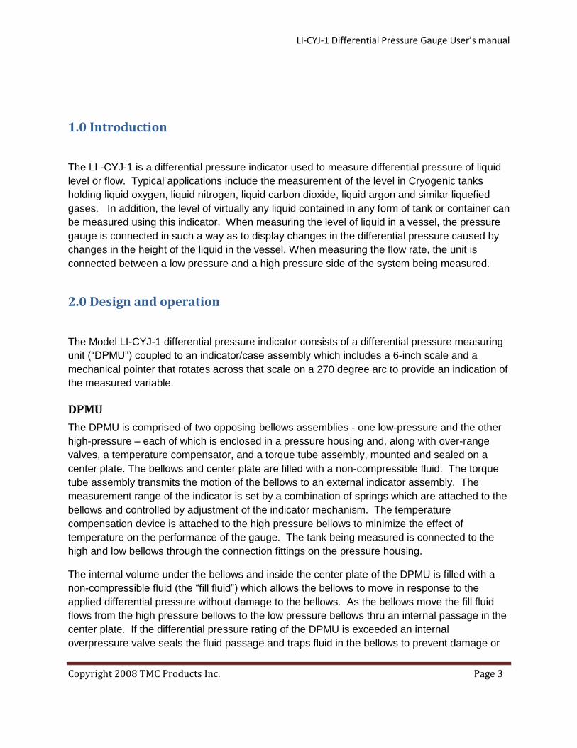
It is recommended that installation utilize a 3-valve manifold or independent high, low, and
balance valve configuration between the process connections and the indicator as indicated in
Figure 1. A 3-valve configuration will allow the unit to be placed into service without
unnecessary risk of over-range exposure and will also facilitate taking the unit out of service and
re-setting the indicator zero reading after re-placing the unit into service.
LI-CYJ-1 Differential Pressure Gauge User’s manual
Copyright 2008 TMC Products Inc. Page 5
Figure 1. 3-Valve method of connecting the indicator and the storage tank.
Install the unit using the wall/pipe mount bracket per the drawing shown in Figure 2 (a) and 2(b).
If the indicator is to be panel mounted, use the drawing shown in Figure 3 for dimensional
reference.

LI-CYJ-1 Differential Pressure Gauge User’s manual
Copyright 2008 TMC Products Inc. Page 6
Figure 2 (a) Rear View – Wall and Pipe Mount.
Figure 2(b): Side View: Wall and Pipe Mount.
LI-CYJ-1 Differential Pressure Gauge User’s manual
Copyright 2008 TMC Products Inc. Page 7
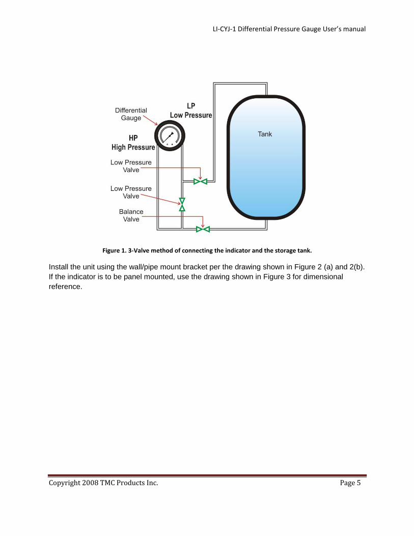
The indicator zero may have to be adjusted prior to use. This can be done before or after
mounting. If it is done before mounting be sure the indicator is orientated the same as it will be
in the final mounting configuration. Mounting orientation can affect the indicator zero position.
Follow the instructions in Section 4 to adjust the indicator zero.
Figure 3
3.0 Placing the indicator in service
When placing the indicator in service:
• Start with the Low Pressure, High Pressure and Balance valves closed
• Open the Balance Valve
• Open the High Pressure Valve
• Close the Balance Valve
• Open the Low Pressure Valve
4.0 Zero position adjustment
LI-CYJ-1 Differential Pressure Gauge User’s manual
Copyright 2008 TMC Products Inc. Page 8
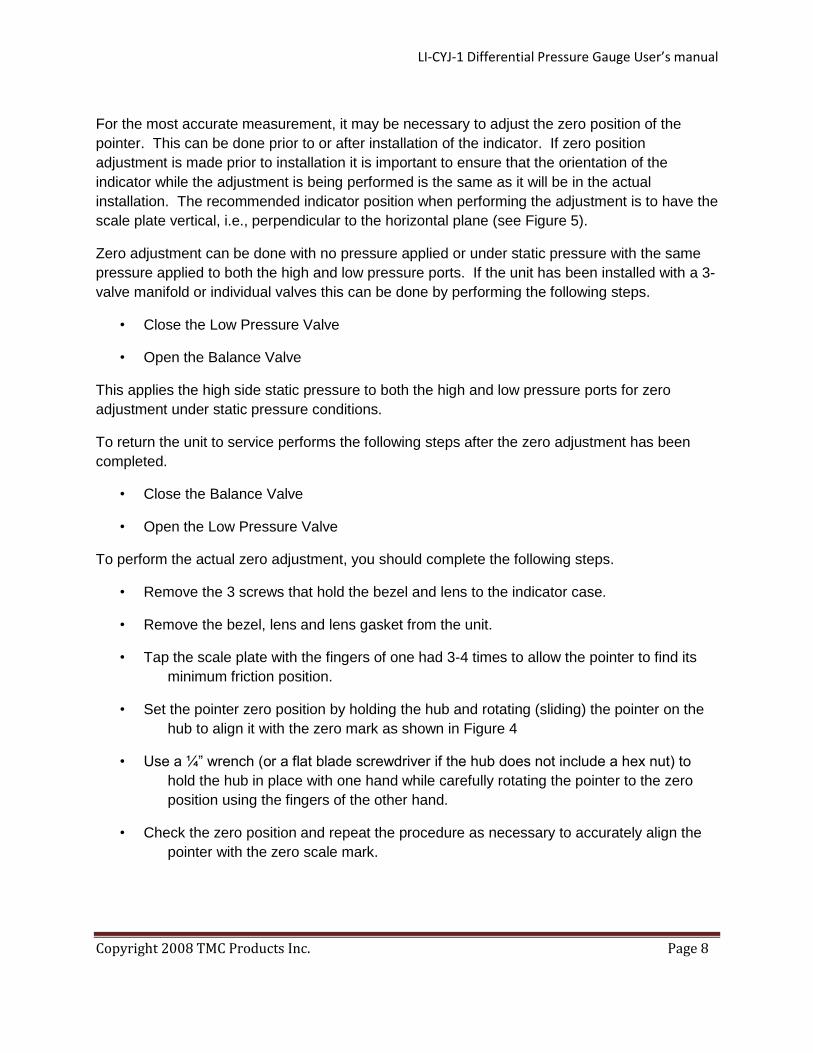
For the most accurate measurement, it may be necessary to adjust the zero position of the
pointer. This can be done prior to or after installation of the indicator. If zero position
adjustment is made prior to installation it is important to ensure that the orientation of the
indicator while the adjustment is being performed is the same as it will be in the actual
installation. The recommended indicator position when performing the adjustment is to have the
scale plate vertical, i.e., perpendicular to the horizontal plane (see Figure 5).
Zero adjustment can be done with no pressure applied or under static pressure with the same
pressure applied to both the high and low pressure ports. If the unit has been installed with a 3-
valve manifold or individual valves this can be done by performing the following steps.
• Close the Low Pressure Valve
• Open the Balance Valve
This applies the high side static pressure to both the high and low pressure ports for zero
adjustment under static pressure conditions.
To return the unit to service performs the following steps after the zero adjustment has been
completed.
• Close the Balance Valve
• Open the Low Pressure Valve
To perform the actual zero adjustment, you should complete the following steps.
• Remove the 3 screws that hold the bezel and lens to the indicator case.
• Remove the bezel, lens and lens gasket from the unit.
• Tap the scale plate with the fingers of one had 3-4 times to allow the pointer to find its
minimum friction position.
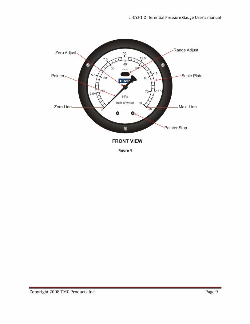
• Set the pointer zero position by holding the hub and rotating (sliding) the pointer on the
hub to align it with the zero mark as shown in Figure 4
• Use a ¼” wrench (or a flat blade screwdriver if the hub does not include a hex nut) to
hold the hub in place with one hand while carefully rotating the pointer to the zero
position using the fingers of the other hand.
• Check the zero position and repeat the procedure as necessary to accurately align the
pointer with the zero scale mark.
LI-CYJ-1 Differential Pressure Gauge User’s manual
Copyright 2008 TMC Products Inc. Page 9
Figure 4

LI-CYJ-1 Differential Pressure Gauge User’s manual
Copyright 2008 TMC Products Inc. Page 10
Figure 5. Zero Adjustment.
The range of the instrument can be adjusted by using a 2 mm wrench to rotate the Rand-
Adjustment Screw (see Figure 6) that is accessible through the slot in the scale plate. Only a
small range adjustment can be performed using this procedure. If an adjustment greater than a
percent or so is required than a complete recalibration may be necessary. Please follow the
instructions on the TMC web site for complete recalibration or return the unit for recalibration.

LI-CYJ-1 Differential Pressure Gauge User’s manual
Copyright 2008 TMC Products Inc. Page 11
Figure 6. Range Adjustment Assembly.

LI-CYJ-1 Differential Pressure Gauge User’s manual
Copyright 2008 TMC Products Inc. Page 12
5.0 Parts diagram
Figure 7: Parts diagram.

LI-CYJ-1 Differential Pressure Gauge User’s manual
Copyright 2008 TMC Products Inc. Page 13
Item Description Part Number Qty
1 Case Assembly (includes DPMU and
meter movement)
1
2 Bezel (Part Of Item #10) 1
3 Lens (Part Of Item #10) 1
4 O-Ring (Part Of Item #10) 1
5 Scale Plate 3
6 Pointer Assembly
White
1
Black
7 Snubber 2
8 Scale Plate Screw 4
9 Bezel Screw 4
10 Bezel Assembly
11 Screw Slotted Set 1
12 Nut, Hex
LI-CYJ-1 Differential Pressure Gauge User’s manual
Copyright 2008 TMC Products Inc. Page 14
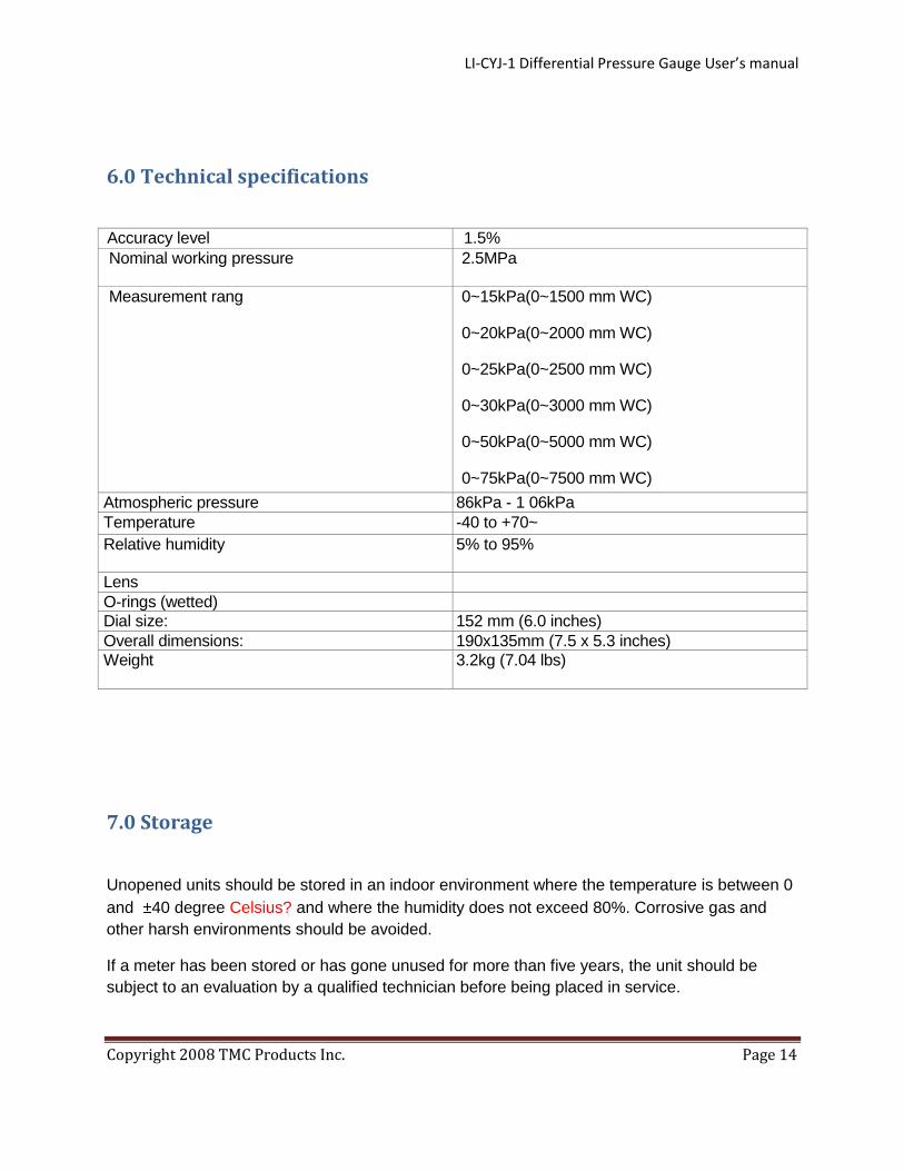
6.0 Technical specifications
Accuracy level 1.5%
Nominal working pressure 2.5MPa
Measurement rang 0~15kPa(0~1500 mm WC)
0~20kPa(0~2000 mm WC)
0~25kPa(0~2500 mm WC)
0~30kPa(0~3000 mm WC)
0~50kPa(0~5000 mm WC)
0~75kPa(0~7500 mm WC)
0~1 00kPa(0~1 0000 mm WC)
0~125kPa(0~12500 mm WC)
0~150kPa(0~15000 mm WC)
0~200kPa(0~20000 mm WC)
0~250kPa(0~25000 mm WC)
Atmospheric pressure 86kPa - 1 06kPa
Temperature -40 to +70~
Relative humidity 5% to 95%
Lens
O-rings (wetted)
Dial size: 152 mm (6.0 inches)
Overall dimensions: 190x135mm (7.5 x 5.3 inches)
Weight 3.2kg (7.04 lbs)
7.0 Storage
Unopened units should be stored in an indoor environment where the temperature is between 0
and 40 degree Celsius? and where the humidity does not exceed 80%. Corrosive gas and
other harsh environments should be avoided.
If a meter has been stored or has gone unused for more than five years, the unit should be
subject to an evaluation by a qualified technician before being placed in service.
LI-CYJ-1 Differential Pressure Gauge User’s manual
Copyright 2008 TMC Products Inc. Page 15
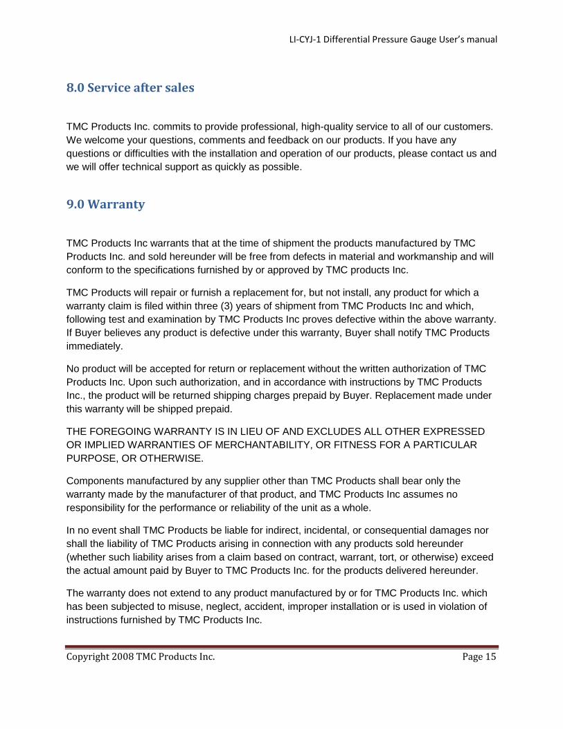
8.0 Service after sales
TMC Products Inc. commits to provide professional, high-quality service to all of our customers.
We welcome your questions, comments and feedback on our products. If you have any
questions or difficulties with the installation and operation of our products, please contact us and
we will offer technical support as quickly as possible.
9.0 Warranty
TMC Products Inc warrants that at the time of shipment the products manufactured by TMC
Products Inc. and sold hereunder will be free from defects in material and workmanship and will
conform to the specifications furnished by or approved by TMC products Inc.
TMC Products will repair or furnish a replacement for, but not install, any product for which a
warranty claim is filed within three (3) years of shipment from TMC Products Inc and which,
following test and examination by TMC Products Inc proves defective within the above warranty.
If Buyer believes any product is defective under this warranty, Buyer shall notify TMC Products
immediately.
No product will be accepted for return or replacement without the written authorization of TMC
Products Inc. Upon such authorization, and in accordance with instructions by TMC Products
Inc., the product will be returned shipping charges prepaid by Buyer. Replacement made under
this warranty will be shipped prepaid.
THE FOREGOING WARRANTY IS IN LIEU OF AND EXCLUDES ALL OTHER EXPRESSED
OR IMPLIED WARRANTIES OF MERCHANTABILITY, OR FITNESS FOR A PARTICULAR
PURPOSE, OR OTHERWISE.
Components manufactured by any supplier other than TMC Products shall bear only the
warranty made by the manufacturer of that product, and TMC Products Inc assumes no
responsibility for the performance or reliability of the unit as a whole.
In no event shall TMC Products be liable for indirect, incidental, or consequential damages nor
shall the liability of TMC Products arising in connection with any products sold hereunder
(whether such liability arises from a claim based on contract, warrant, tort, or otherwise) exceed
the actual amount paid by Buyer to TMC Products Inc. for the products delivered hereunder.
The warranty does not extend to any product manufactured by or for TMC Products Inc. which
has been subjected to misuse, neglect, accident, improper installation or is used in violation of
instructions furnished by TMC Products Inc.

LI-CYJ-1 Differential Pressure Gauge User’s manual
Copyright 2008 TMC Products Inc. Page 16
The warranty does not extend to or apply to any unit which has been repaired or altered ant any
place other than at a TMC Products Inc. authorized service location by persons not expressly
approved by TMC Products Inc.
Disclaimer:
TMC Products Inc makes no warranty of any kind with regard to these manual, materials
referenced to, attached to or provided with, including, but not limited to, implied warranties of
merchantability and fitness for a particular purpose. TMC Products Inc. shall not be liable for
errors contained in this manual, including materials attached to or referenced herein, or
provided with, or for incidental or consequential damages in connection with furnishing,
performance, or use of this information,. The information contained in this manual (along with
referenced, attached or provided materials) is subject to change without notice. The contents of
this manual and all attached/provided/referenced materials may be revised without prior notice.
10.0 TMC Smart Part Number/Ordering Guide
In order to make the ordering process as smooth as possible for our customers, TMC Products
Inc. has implemented a Smart Part ordering system that allows our customers to build their own
specific indicators by specifying in the order precisely what components and specifications they
wish in their indicator. Use the handy chart below as a guide for creating application specific
indicator

LI-CYJ-1 Differential Pressure Gauge User’s manual
Copyright 2008 TMC Products Inc. Page 17


![DIGITAL DIFFERENTIAL COMPACT PRESSURE TRANSMITTER Digital Pressure Gauge … · 2019. 12. 3. · PRESSURE GAUGE Digital Pressure Gauge & Digital Manometer [Input setting 2 ] SETTING](https://img.dokumen.tips/doc/110x75/60b001340dff284ff85b02be/digital-differential-compact-pressure-transmitter-digital-pressure-gauge-2019-12.jpg)