Embed Size (px)
Citation preview

DUAL BAND DIELECTRIC RESONATOR ANTENNA
OPERATES AT 2.4 GHz AND 5.4 GHz
SYED FIRDAUS BIN SYED RADZUAN
UNIVERSITI TEKNOLOGI MALAYSIA

DUAL BAND DIELECTRIC RESONATOR ANTENNA
OPERATES AT 2.4 GHz AND 5.4 GHz
SYED FIRDAUS BIN SYED RADZUAN
A project report submitted in partial fulfillment of the
requirements for the award of the degree of
Master of Engineering (Electric – Electronics & Telecommunications)
Faculty of Electrical Engineering
Universiti Teknologi Malaysia
JUNE 2012

iii
Dedicated to my beloved Wife, Kids, Father, Mother and Family Members. Without their
support, I’m nobody.

iv
ACKNOWLEDGEMENT
Praise to Allah that this thesis and project could be completed successfully. Without His
permission and willing, the whole progress would not come to an end.
Next is to my supervisor, Dr Mohd Haizal bin Jamaluddin for his taught and lessons. All
his knowledge and experienced shared together were very meaningful in life and also in this
research. Only Allah can pay your kindness and may Allah bless you.
To my lovely wife Ms Azzah binti Haji Othman, thanks for everything and become my
companion in life. She’s the one who always next to me giving hope and sacrifice lots during my
project progress.
Apart from that, thanks to my parents and family members for all their support and
courage. Without all these, I could not stand until the last drop.
Lastly to all my classmates in MELB1BKA group. We studied together, and we will
succeed together.

v
ABSTRACT
This thesis explains about the design of dual band antenna by using a dielectric material.
The antenna is made from a dielectric resonator antenna (DRA) with a permittivity, r , is 10.
Rectangular DRA is used to ease the fabrication process. The operating frequency chosen to be design is
2.4 GHz and 5.4 GHz. Notched DRA technique is used for dual band application purpose. In order to
drive the antenna to function, it is placed on top of the ground plane. FR4 board is chosen as a ground
plane for this research with a dielectric constant is 4.6. Alphabet “I” is used in this study for the aperture
coupling at the substrate. Meanwhile, for the feeding line, microstrip line is used to match with
50 network. The simulation is run by using Computer Simulation Technology (CST) software. This
software provides 3D design of the antenna and easier visualizes the antenna properly. The result is then
compared to the actual result obtained by measurement. The fabricated product is attached to a network
analyzer via SMA connector. S11 output obtained during simulation and measurement will be discussed
thoroughly.

vi
ABSTRAK
Tesis ini menerangkan tentang reka bentuk antena dwi jalur dengan menggunakan bahan
dielektrik. Antena itu dibuat daripada antena resonator dielektrik (DRA) dengan ketelusan, r
ialah 10. Segiempat tepat DRA digunakan untuk memudahkan proses fabrikasi. Frekuensi
operasi yang dipilih untuk reka bentuk adalah 2.4 GHz dan 5.4 GHz. Teknik takuk DRA
digunakan untuk mendapatkan antenna dwi jalur. Bagi membolehkan antena berfungsi, ia
diletakkan di atas satah bumi. Papan FR4 dipilih sebagai satah bumi untuk kajian ini dengan
pemalar dielektrik ialah 4.6. Huruf "I" digunakan dalam kajian ini untuk gandingan “aperture”
pada substrat. Sementara itu, bagi talian suapan, selaras mikrostrip digunakan untuk dipadankan
dengan rangkaian 50 . Simulasi dijalankan dengan menggunakan perisian “Computer
Simulation Technology” (CST). Perisian ini menyediakan reka bentuk 3D antena agar mudah
membayangkan bentuk antena dengan betul. Hasilnya kemudian dibandingkan dengan hasil
sebenar yang diperolehi oleh pengukuran. Produk yang direka dilampirkan kepada penganalisa
rangkaian melalui penyambung SMA. Hasil keluaran S11 yang diperolehi semasa simulasi dan
pengukuran akan dibincangkan.

vii
TABLE OF CONTENTS
CHAPTER TITLE PAGE
TITLE
DECLARATION
DEDICATION iii
ACKNOWLEDGEMENT iv
ABSTRACT v
ABSTRAK vi
TABLE OF CONTENTS vii
LIST OF TABLES xi
LIST OF FIGURES xii
LIST OF ABBREVIATIONS xv
LIST OF APPENDICES xvi
1 INTRODUCTION 1
1.1. Introduction 1
1.2. Problem Statement 3

viii
1.3. Objective 3
1.4. Scope Of Project 3
1.5. Project Methodology 4
1.5.1. Literature Review 5
1.5.2. Design Of DRA Operates At 2.4 GHz and 5.4 GHz 6
1.5.3. Fabrication 6
1.5.4. Measurement 6
1.6. Specification 7
1.7. Thesis Outline 8
2 LITERATURE REVIEW 9
2.1. Introduction 9
2.2. DRA Configuration 9
2.2.1. Notched Rectangular DRA 9
2.2.2. Annular DRA 10
2.2.3. Multi Segment DRA (MSDRA) 11
2.2.4. Parasitic DRA 12
2.3. Excitation Method 13
2.3.1. Coaxial And Microstrip Feed Line 14

ix
2.3.2. Slot Waveguide 14
2.3.3. Image Guide 15
2.4. DRA Coupling 15
2.4.1. Aperture Coupling 16
2.4.2. Probe Coupling 16
2.4.3. Microstrip Line Coupling 17
2.5. DRA Size Calculation 18
3 DESIGN METHODOLOGY 21
3.1. Introduction 21
3.2. DRA Design 21
3.3. Substrate Design 23
3.4. Matching Network 31
3.5. DRA Cutting Technique 33
4 RESULT AND DISCUSSION 35
4.1. Intoduction 35
4.2. S11 Output For Substrate Only 35
4.3. S11 Output When Placing DRA 36

x
4.4. E Field Radiation Pattern At 2.4 GHz And 5.4 GHz 38
4.5. H Field Radiation Pattern At 2.4 GHz And 5.4 GHz 39
4.6. Simulation Result 41
4.7. Measurement Result 42
4.8. Summary 45
5 CONCLUSION AND FUTURE WORK 48
5.1. Conclusion 48
5.2. Future Work 48
REFERENCES 50
Appendices A – B 52 - 55
xi
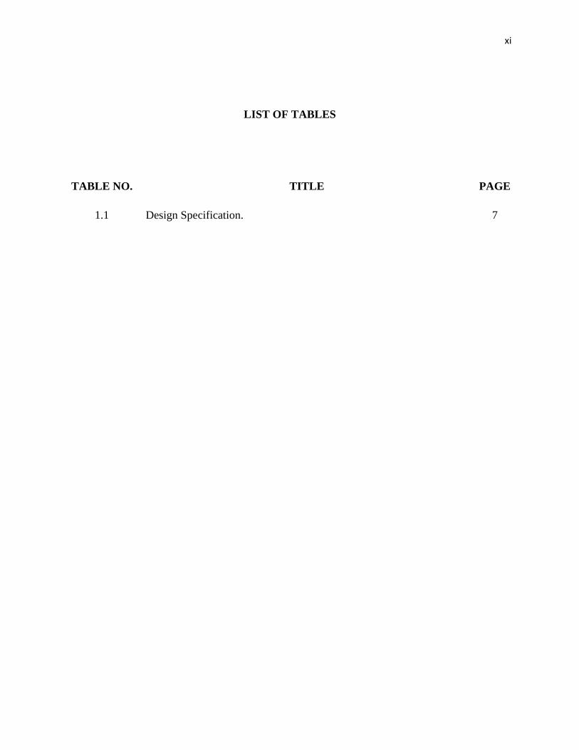
LIST OF TABLES
TABLE NO. TITLE PAGE
1.1 Design Specification. 7

xii
LIST OF FIGURES
FIGURE NO. TITLE PAGE
1.1 DRA shapes – cylindrical, rectangular and hemispherical. 2
1.2 Overall project processes. 5
1.3 Expected result. 8
2.1 Notched rectangular DRA. 10
2.2 Annular DRA. 11
2.3 MSDRA. 12
2.4 Parasitic DRA. 13
2.5 Feeding line. 14
2.6 Type of coplanar structure. 15
2.7 Slot. 16
2.8 Probe coupling. 17
2.9 Difference between side coupling and direct coupling. 18
3.1 DRA initial cutting. 22
3.2 Notched DRA. 22
3.3 Actual DRA dimension. 23
xiii
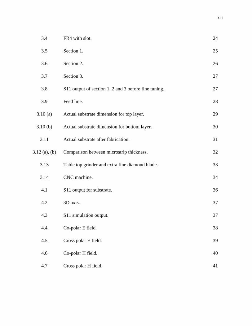
3.4 FR4 with slot. 24
3.5 Section 1. 25
3.6 Section 2. 26
3.7 Section 3. 27
3.8 S11 output of section 1, 2 and 3 before fine tuning. 27
3.9 Feed line. 28
3.10 (a) Actual substrate dimension for top layer. 29
3.10 (b) Actual substrate dimension for bottom layer. 30
3.11 Actual substrate after fabrication. 31
3.12 (a), (b) Comparison between microstrip thickness. 32
3.13 Table top grinder and extra fine diamond blade. 33
3.14 CNC machine. 34
4.1 S11 output for substrate. 36
4.2 3D axis. 37
4.3 S11 simulation output. 37
4.4 Co-polar E field. 38
4.5 Cross polar E field. 39
4.6 Co-polar H field. 40
4.7 Cross polar H field. 41

xiv
4.8 S11 output from simulation. 42
4.9 Actual S11 output. 43
4.10 Actual DRA. 44
4.11 S11 output when using glue. 45
4.12 Comparison between simulation and actual measurement. 46
4.13 Comparison between simulation and actual measurement when using
glue.
47
xv
LIST OF ABBREVIATIONS
DRA - Dielectric Resonator Antenna.
r - Permittivity.
CST - Computer Simulation Technology.

xvi
LIST OF APPENDICES
APPENDIX TITLE PAGE
A Substrate Datasheet. 52
B DRA Datasheet. 55
CHAPTER 1
INTRODUCTION
1.1. Introduction.
Dielectric resonator antenna (DRA) study and application has been widely used for more
than 25 years ago [1]. It was started in the early 1980’s. The first study was conducted by Stuart
Long and Liang Shen. Their investigation involved printed circuit radiators. These investigations
sponsored by US Army Research Office. From their investigation, it was found that microstrip
antenna is less efficient at high frequencies. It is due to high ohmic loss and increase in power
consumption.
In summer 1981, Stuart Long proposed to study cylindrical dielectric resonator. In this
study, he concludes that choosing a correct dimension and dielectric constant can produce an
efficient antenna with a maximum radiation.
Stuart Long’s study is then furthered by Mark McAllister. He studied rectangular and
hemispherical DRA shape. Apart from that, he also varied the size and the materials used in
DRA. The first paper that he studied was “The Resonant Cylindrical Dielectric Cavity Antenna”
[2]. After that, he came out with his second paper title “Rectangular Dielectric Resonator
Antenna” [3]. Even though this is his second paper, but so happen that this is the first paper to be
printed out. From there, this is where the term “Dielectric Resonator Antenna” comes from.
After several researches, this term is then standardized to avoid any misconception.
Over the years, the studies of DRA become famous throughout the whole world. People
are more concern of its performance and try to fully utilize the DRA characteristics [4]. The

2
study involved design for compact DRA, wide impedance bandwidth, low profile and high gain
antenna. Besides, the fabrication technique also has been studied.
DRA is basically made from dielectric material with no metallic loss [5]. It comes in
various shapes [6] such as cylindrical, hemispherical, elliptical, pyramidal, rectangular and
triangular as shown in Figure 1.1. These are common DRA shapes used in study. In order to
make DRA radiates the signal, it needs a mechanism to excite it. Some of the techniques are
coaxial probe, microstrip line or coplanar waveguide.
Figure 1.1 : DRA shapes – cylindrical, rectangular and hemispherical.
There are few points of interest DRA is preferred in the design compared to conventional
antenna. Conventional antenna requires high power in order for it to operate. Differ with DRA
which only requires small amount of power to operate. Besides that, size of the conventional
antenna is big rather than DRA size which is small enough to radiate the same signal bandwidth.
In terms of cost effectiveness, DRA is the cheapest to implement because of its material. Overall,
DRA manage to get a wide impedance bandwidth as well as a high antenna gain.
DRA is an important element in antenna design. When DRA is placed in an open
environment, power losses radiate the surrounding field [7]. Due to its size, lightweight and cost
effectiveness, DRA become a popular choice in antenna and mobile design. In this project, DRA
will be used to test the performance and compared with the simulation result.
3
1.2. Problem Statement.
Most of the antenna in the market can only cater for a single frequency application. It is
using a conventional microstrip antenna. Thus, for application that needs a dual frequency, two
separate antennas are needed.
Apart from that, microstrip antenna can only give small bandwidth which is less than 5%.
Besides, it needs a large area for the antenna to operate.
Meanwhile, DRA have more advantages compared to microstrip antenna. It can give
more than 5% bandwidth and can operate using a smaller size of antenna if compared to
microstrip type antenna. Bandwidth enhancement will be emphasize in this paper.
1.3. Objective.
To design, fabricate and measure a high bandwidth rectangular DRA that operates at 2.4
GHz and 5.4 GHz.
1.4. Scope Of Project.
The scope of this project describes the design of a dual band antenna by using a dielectric
resonator material. Frequency proposed is 2.4 GHz and 5.4 GHz. The simulation is run using
Computer Simulation Technology (CST) software. A notched DRA technique will be used for
dual band application. Apart from that, alphabet slot is used as an aperture. The effect of using
adhesive when placing DRA on top of ground plane will be study as well.
4
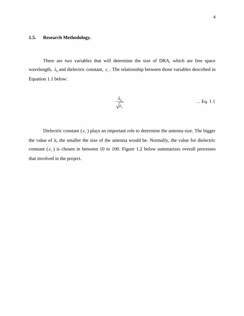
1.5. Research Methodology.
There are two variables that will determine the size of DRA, which are free space
wavelength, 0 and dielectric constant, r . The relationship between those variables described in
Equation 1.1 below:
0
r
… Eq. 1.1
Dielectric constant ( r ) plays an important role to determine the antenna size. The bigger
the value of it, the smaller the size of the antenna would be. Normally, the value for dielectric
constant ( r ) is chosen in between 10 to 100. Figure 1.2 below summarizes overall processes
that involved in the project.
5
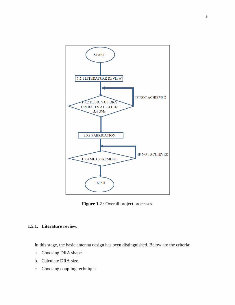
Figure 1.2 : Overall project processes.
1.5.1. Literature review.
In this stage, the basic antenna design has been distinguished. Below are the criteria:
a. Choosing DRA shape.
b. Calculate DRA size.
c. Choosing coupling technique.

6
d. Calculate the strip line width.
e. Choosing the substrate permittivity.
1.5.2. Design.
After all the necessary criteria have been finalized, the design is then tested by using a
computer simulation first. “Computer Simulation Technology” (CST) software is used to verify
the design. Simulation is needed to avoid wastage of time, material and others incurred during
fabrication process. Return loss from the simulation is captured and verified. If so happen that
the design is not according to the specification, the design process needs to be repeated. Should
the simulation result satisfy with the specification, then next process can be proceed.
1.5.3. Fabrication.
Layout is then printed to substrate ground plane. Probe is then attached to the strip line to
capture the result. Next, DRA is place on top of the ground plane.
1.5.4. Measurement.
The prototype is then place inside anechoic chamber to get accurate result. This chamber
is specially design to prevent any noise from interfering the antenna radiation when it is
operating. Actual result is then compared to the simulation result obtained from previous stage.
The design is confirmed when the actual and simulation result matched with each other. Should
the measurement result is differ, then the fabrication process need to re do again.

7
1.6. Specification.
From all the literature above, the DRA design that will be used in this project is as Table
1.1 below.
Table 1.1 : Design Specification.
DRA Type Rectangular
Frequency 2.4 GHz / 5.4 GHz
DRA Configuration Notched
Excitation Method Microstrip Feed Line
DRA Coupling Aperture Coupling
The expected result from these configurations would have a waveform similar like Figure
1.3 below. Even at 10dB return loss, the antenna still manages to give the frequency needed for
the application. The result for the measurement is taken from the real antenna design. This case
is for ideal case. Some noises and spikes should be expected in the real measurement.

8
Figure 1.3 : Expected result.
1.7. Thesis Outline.
This thesis is divided into five (5) main chapters that cover research for Dual Band
Dielectric Resonator Antenna.
Chapter 2 describes on literature review related to DRA. In chapter 3, it is discussed on
methodology to realize the actual product. After that, in chapter 4 it is discussed on simulation
and measurement result. Lastly in chapter 5, is a conclusion of the research as well as future
work proposed.

REFERENCES
1. Stuart A. Long and Ellen M. O’Connor, “The History of the Development of the
Dielectric Resonator Antenna”, IEEE, 2007, pp 872-875.
2. S.A. Long, M.W. McAllister and L.C. Shen, "The Resonant Cylindrical Dielectric Cavity
Antenna," IEEE Trans. Antennas Propagat.,vol. AP-31, pp. 406-412, May 1983.
3. M.W. McAllister, S.A. Long, and G.L. Conway, "Rectangular Dielectric Resonator
Antenna," Electron. Lett., vol. 19, pp. 218-219, March 1983.
4. Aldo Petosa and Apisak Ittipiboon, “Dielectric Resonator Antennas: A Historical Review
and the Current State of the Art”, IEEE Antennas and Propagation Magazine, volume 52,
no 5, pp 91-116, October 2010.
5. Kwok Wa Leung, Senior Member, IEEE, and Hoi Kuen Ng, Student Member, IEEE,
“Theory and Experiment of Circularly Polarized Dielectric Resonator Antenna With a
Parasitic Patch”, IEEE Transactions On Antennas and Propagation, Volume 51, No 3,
March 2003.
6. S. H. Zainud-Deen, H. A. Malhat, and K. H. Awadalla, “Dielectric Resonator Antenna
Mounted on a Circular Cylindrical Ground Plane”, Progress In Electromagnetics
Research B, Volume 19, pp 427-444, 2010.
7. R. K. Mongia, and P. Bhartia, “Dielectric Resonator Antennas – A Review and General
Design Relations for Resonant Frequency and Bandwidth”, International Journal of
Microwave and Millimeter-Wave Computer-Aided Engineering, 1994, 4, (3), pp 230-247.
51
8. Rohini Yadla, “Novel Designs For Broadband and Compact Dielectric Resonator
Antenna”, Thesis, December 2004.
9. A. Petosa, A. Ittipiboon, Y.M.M. Antar, D. Roscoe and M. Cuhaci, ”Recent Advances in
Dielectric Resonator Antenna Technology”, IEEE Antennas and Propagation Magazine,
Vol. 40, No. 3, June 1998.
10. A. Ittipiboon, A. Petosa, D. Roscoe, and M. Cuhaci, “An investigation of a novel
broadband dielectric resonator antenna,” in IEEE Int. Symp. Antennas Propag. Dig.,
Baltimore, MD, 1998, pp. 2038–2041.
11. Ahmed A. Kishk et al, Dielectric Resonator Antenna, McGraw-Hill, 2007.
12. Antenna Engineering Handbook, Richard C. Johnson, Mc-Graw Hill, 3rd
Edition,
December 1992.
13. Dielectric Resonator Antenna Handbook, Artech House Antennas and Propagation
Library, January 2007.