Embed Size (px)
Citation preview

Installation and Operation Manual
Part # H004423Rev. 5October 2011
®
DSY261RSAEDigital Clock/Elapsed
Time Indicatorwith Code Blue

© American Time2
DSY261RSAE Owner's ManualElectrical Shock HazardWARNING: Hazardous voltage in electrical equipment can cause severe personal injury or death. Inspection, installation, and preventive maintenance should only be performed on equipment to which power has been turned off, disconnected and electrically isolated so no accidental contact can be made with energized parts.
Electrostatic Sensitive DevicesCAUTION: This equipment contains electronic devices that are sensitive to static electric charges. To guarantee protection for the circuitry of this unit, it is required that electrostatic handling precautions be observed when installing or repairing this equipment. Any technician or other personnel working on this unit must wear a static grounding wrist strap or similar device to provide protection of sensitive components.
ATTENTIONOBSERVE PRECAUTIONS
FOR HANDLING
ELECTROSTATICSENSITIVEDEVICES

3© American Time
DSY261RSAE Owner's Manual Table of Contents
American Time140 3rd Street SouthPO Box 707Dassel, MN 55325-0707
Phone: 800-328-8996Fax: 800-789-1882american-time.com
Important Installation and Warranty Information ....................................................................................................4Specifications ............................................................................................................................................................5Description .................................................................................................................................................................6 DSY261RSAE Digital Clock/Timer ....................................................................................................................6 ATSTCS Control Station ...................................................................................................................................7Installation Instructions ...........................................................................................................................................8 DSY261RSAE Installation Instructions ...............................................................................................................8 ATSTCS Installation Instructions ........................................................................................................................9Operation ................................................................................................................................................................10 Power Up .......................................................................................................................................................10 Setting Time ..................................................................................................................................................10 Setting the Up Counter Preset Time ................................................................................................................10 Up Counter Elapsed Time Operation ................................................................................................................11 Setting the Down Counter Preset Time ...........................................................................................................11 Down Counter Elapsed Time Operation ...........................................................................................................11 Free Running Clock Operation .......................................................................................................................12 Synchronous Secondary Clock Operation ......................................................................................................12 Setting the Secondary Clock Mode Switch .....................................................................................................12Code Blue .................................................................................................................................................................13 Operation .......................................................................................................................................................13 Wiring ............................................................................................................................................................13 Important Considerations ...............................................................................................................................14Maintenance ............................................................................................................................................................15Appendix 1: Wiring For 3-Wire Secondary Clocks.....................................................................................................16Appendix 2: Wiring For 4-Wire Secondary Clocks.....................................................................................................17Appendix 3: Using the DSY261RSAE as an Up Counting1 Elapsed Timer Only ..........................................................18Appendix 4: Using the DSY261RSAE as a Down Counting, Elapsed Timer Only .........................................................18Appendix 5: Operators Flowchart .............................................................................................................................19

© American Time4
DSY261RSAE Owner's Manual
IMPORTANT INSTALLATION AND WARRANTY INFORMATION
WARRANTY INFORMATION: American Time (the Manufacturer) provides a limited warranty to the Original Purchaser of this product. The Original Purchaser is the party to whom the Manufacturer issued its Sales Order, generally the Manufacturer’s distributor. In order to preserve this warranty, it is important that only persons who have been properly trained and authorized by the Manufacturer service the product.
Other parties involved in the installation of this product may have also provided a warranty, which may be different than that of the Manufacturer. The Manufacturer will only be responsible to the Original Purchaser and only for theManufacturer’s own warranty. For further information regarding the Manufacturer’s warranty, contact the OriginalPurchaser.
OWNER’S MANUAL: The owner’s manual does not purport to cover all the details or variations in the equipment described, nor does it provide for every possible contingency to be met in connection with installation, operation and maintenance. All specifications subject to change without notice. Should further information be desired or should particular problems arise which are not covered sufficiently, the matter should be referred to the Installer or Original Purchaser listed below.
INSTALLER INFORMATION
COMPANY: INSTALLER: PHONE:
ADDRESS: CITY: STATE: ZIP:
DATE INSTALLED: INSTALLER’S SIGNATURE:
ORIGINAL PURCHASER INFORMATION
COMPANY: PHONE:
ADDRESS: CITY: STATE: ZIP:
PURCHASER’S PURCHASE ORDER NO:
DATE PURCHASED:
ATS SALES ORDER ACKNOWLEDGMENT NO.:
ORIGINAL PURCHASER’S SIGNATURE:
NOTE: A copy of the above-completed information may be required by the Manufacturer for authorization of Warranty services.

5© American Time
DSY261RSAE Owner's Manual Specifications
GENERAL
Weight: ..............................Digital Clock/Timer ............................... 4.27 lb. ...............................ATSTCS Control Station ........................... 0.27 lb.External Dimensions: .........Digital Clock/Timer ............................... 5.375" X 12.375" X 3" ...............................ATSTCS Control Station ........................... 4.63" X 4.56" X 1.25"
SPECIFICATIONS
ELECTRICAL
Power Requirements (Digital Clock/Timer only):Line Voltage: ..................................................................................... 120/240vac 50/60HzNote: Voltage and frequency set by Factory on orderBattery:............................................................................................... 9vdc Rechargeable Ni-Cad BatteryBattery Charger: ................................................................................ 9vdc Direct Current source with ............................................................................................... current limiting resistor. Maximum Current (Digital Clock/Timer only): .................................... 56 mA (26mA for 240vac version)Memory Retention on Loss of Line Voltage: ..................................... 4 hours with fully charged batteryDistance of ATSTCS from Digital Clock/Timer: ................................. 30-ft maximum with 22 AWG stranded wire ............................................................................................... with minimum 1/32" thick insulationClock Circuits: ................................................................................... 3.0mA. max. @ 24vac/120vacCode Blue Circuits: ............................................................................ 3.0mA. max. @ 12vac/vdc-30vac/vdc
ENVIRONMENTAL
Ambient Operating Range: ................................................................ 10°C to 49°C (50°F to 120°F)Recommended Storage Temperature: .............................................. -30°C to 45°C (-22°F to 113°F) ............................................................................................... for six months maximumHumidity: ............................................................................................ 85 %RH at 30°C (86°F)
OPERATION
Modes Available: ................12 hour or 24-hour non-system clock 12 hour secondary clock Incrementing timer with programmable preset value and start/stop capability Decrementing timer with programmable preset value and start/stop capability Code Blue incrementing timerAccuracy: .............................................................................with line voltage applied - line synchronous with line voltage not applied - ± 0.005 % at 25°CIndications: ........................Digital Clock/Timer hours and minutes - 2.3", bright red, seven segment LED’s hours and minutes are separated by a colon seconds - 1.0", bright red, seven segment LED’s ...............................ATSTCS Control Station 2 second audible alarm

© American Time6
DSY261RSAE Owner's ManualA
pp
en
dix
Main
ten
an
ce
Cod
e B
lue
Op
era
tion
Inst
allati
on
Desc
rip
tion
Clock/Timer Description
The DSY261RSAE Digital Clock/Timer is a six-digit multi-function clock/timer. The DSY261RSAE functions as a 12-hour or 24 hour stand-alone clock. The DSY261RSAE can also be wired as a 12-hour secondary clock.
When combined with the ATSTCS Control Station, the DSY261RSAE can also be used as an up or down counting elapsed timer. The elapsed timers can be started, stopped, resumed, and reset. Both timer modes have a programmable preset value. When the timer reaches the preset value, a two-second audible alarm sounds from the ATSTCS. The DSY261RSAE contains a Code Blue up counting elapsed timer that overrides all other modes of operation.
DSY261RSAE Digital Clock/Timer
START/STOP RESET
INCREMENT ENTER
RUN
SET
UP
DOWN
CLOCK
4 9/16”
4 1
/2”
Control Station
12 3/8”
5 3/8”
3.0”
Digital Clock/Timer
ATSTCS Control Station

7© American Time
DSY261RSAE Owner's ManualA
pp
en
dix
Main
ten
an
ce
Code B
lueO
pera
tion
Insta
llatio
nD
esc
riptio
nControl Station Switch Functions
START/STOP RESET
INCREMENT ENTER
RUN
SET
UP
DOWN
CLOCK
RESET
ENTER
RUN
SET
UP
DOWN
CLOCK
START/STOP
INCREMENT
Run/Set Switch - Set Position: This position is used to set a preset up or down counting time (Timer). It is also
used to reset the Code Blue timer.
This position is not used for setting time. The controller will allow you to enter in
a 12/24 hour mode and set a time. However the time will be controlled and
updated by the SiteSync IQ system controller.
Run Position: This position is used to permit Clock/Timer to operate.
Up/Clock/Down Switch - Up Position: This position is used to choose up counting elapsed timer mode.
Clock Position: This position is used to choose clock mode.
Down Position: This position is used to choose down counting elapsed timer mode.
Start/Stop/Increment Switch - This button is used to start, stop, and resume timer count, when Run/Set Switch is in the Run
position (Code Blue timer can only be stopped).
This button is also used to increment/advance the number value being set when the Run/Set Switch
is in Set position.
Reset/Enter Switch - This button is used to used to return a timer (excluding the Code Blue timer) to the beginning of
its count, when the Run/Set Switch is in Run position.
This button can also be used to select a field (i.e. format, minute digits, hour digits) when the Run/
Set Switch is in Set position.

© American Time8
DSY261RSAE Owner's ManualA
pp
en
dix
Main
ten
an
ce
Cod
e B
lue
Op
era
tion
Inst
allati
on
Desc
rip
tion
Clock/Timer Installation
The Digital Clock/Timer can be mounted to a single or double gang box. To install the Digital Clock/Timer, follow the instructions below. Ensure that installation conforms to the National Electrical Code and local wiring codes.
CAUTION: Electric Shock Hazard! Ensure that NO electrical power is present on any wire before installation.
u Remove the four sheet metal screws that hold the cover assembly and back plate assembly together. Be sure to keep the sheet metal screw.
v Make electrical connections (hot, neutral, ground wires) to non-switched electrical circuit wiring using UL approved wire nuts. Route field wiring away from sharp projections, corners and internal components. for Molex, white to negative/common, black to positive/hot and green to ground.
w Pull the eight wires from the control station through the second bushing of the back plate assembly. The 120vac wires and control station wires should not be run through the same bushing.
x Join the two Molex connectors together, placing excess wiring and Molex connectors into the gang box.
y Mount the back plate assembly to the single or double gang box.
z Connect field wiring interconnecting the Clock/Timer with the ATSTCS Control Station to the appropriate terminals of the Digital Clock/Timer See wiring detail on next page.
Chassis ground MUST be connected to conduit/Earth ground to provide proper protection from electric shock.
CAUTION: Electric Shock Hazard! When making installation, route field wiring away from sharp projections, corners, and internal components.
Re-attach the cover assembly to the back plate assembly using the sheet metal screws removed in step 1.
Apply power to the circuit and confirm correct operation.
Installation Schematic

9© American Time
DSY261RSAE Owner's ManualA
pp
en
dix
Main
ten
an
ce
Code B
lueO
pera
tion
Insta
llatio
nD
esc
riptio
nControl Station Installation
The ATSTCS Control Station can be mounted to a double gang box, 11/2 inch deep or deeper. The Control Station can be mounted up to 30 feet away from the Digital Clock/Timer. The recommended minimum interconnecting field wire size is #22.8 AWG stranded wire. Ensure that installation conforms to the National Electrical Code and local wiring codes.CAUTION: Electric Shock Hazard! Ensure that no electrical power is present on any wire before installation.
u Pull interconnecting field wires into the double gang box.
v Connect field wiring interconnecting the ATSTCS Control Station with the Digital Clock/Timer to the appropriate wires of the Control Station. See wiring detail below.
w Mount the Control Station to the double gang box using the machine screws provided.
K2+
K2–
K1+
K1–
12VA
C
12VA
C
UN
RE
G
GN
D
PIE
ZO
S5
S4
S3
S2
S1
RE
D
BLA
CK
VIO
LET
GR
EY
BR
OW
N
BLU
E
OR
AN
GE
YE
LLO
W
CHASSIS
NEUTRAL
120 VAC
50/60Hz
TER
MIN
ALS
K2+
AN
D
K2–
AR
E U
SE
D F
OR
C
OD
E B
LUE
MO
DE
Typical wiring for the Digital Clock/Timer with Control Station
PIEZOBUZZER
30 ft. maximum #22 AWG wire (minimum) with 1/32" insulation (minimum)
RESETENTER
START/STOPINCREMENT
UP
CLO
CK
DO
WN
SET
RUN

© American Time10
DSY261RSAE Owner's ManualA
pp
en
dix
Main
ten
an
ce
Cod
e B
lue
Op
era
tion
Inst
allati
on
Desc
rip
tion
Operation
Powering UpBefore applying power, place the SET/RUN switch to the RUN position and the UP/DOWN/CLOCK switch to the CLOCK position.
Apply power to the unit. The displays may rotate during the power on self test and then a version number will appear for a few seconds. The DSY261RSK will display 1:00:00 and begin keeping time. If the backup battery is not depleted, the self test will be bypassed and the DSY261RSAE may display a time other than 1:00:00.
Setting TimeWith the UP/DOWN/CLOCK switch still in the CLOCK position:
Set the SET/RUN switch to the SET position.
The clock will now prompt for a 12 or 24 hour format. Press the INCREMENT switch until the desired format is shown and then press ENTER.
The clock will now prompt for time. The hours digits will be flashing. Press the INCREMENT switch until the desired hour is shown and then press ENTER. The minutes digits will be flashing. Press the INCREMENT switch until the until the desired minutes are shown and then press ENTER. Press the INCREMENT switch again to set the desired seconds and then press ENTER.
The display will flash donE. Press the SET/RUN switch back to RUN when you want timekeeping to begin at the time you entered.
The clock will now keep time as a free running clock or as a slave if connected to a master clock and in 12 hour format..
Setting the Up Counter Preset TimeIf you want to use the alarm and hold feature with the UP timer, you will need to set a preset time for the UP timer.
Set the UP/DOWN/CLOCK switch to the UP position.
Set the SET/RUN switch to the SET position. The hours digits will be flashing.
Using the INCREMENT switch, set the desired hours for the preset time, then press ENTER. The minutes digits will now be flashing.
Set the desired minutes the same way, then press ENTER. The seconds digits will then be flashing.
Set the desired seconds the same way, then press ENTER. The display will then flash donE.
Set the SET/RUN switch back to the RUN position.
Note: A preset of 00:00:00 allows the digital clock/timer to be used as a standard elapsed timer with a maximum elapsed time of 30:59:59.

11© American Time
DSY261RSAE Owner's ManualA
pp
en
dix
Main
ten
an
ce
Code B
lueO
pera
tion
Insta
llatio
nD
esc
riptio
nOperation
Up Counter Elapsed Time OperationOnce the desired preset value has been set, the unit is now ready to function as an UP count elapsed timer.
uBe sure the SET/RUN switch is in the RUN position.
vSet the UP/DOWN/CLOCK switch to the UP position.
wPress RESET to display 00:00:00.
xPress the START/STOP switch to begin counting elapsed time.
yPress the START/STOP switch again to stop and hold the count.
zPress the START/STOP switch again to resume elapsed time counting.
To start over press RESET to display 00:00:00 again.
When the timer reaches the preset value, it will sound the audible alarm for 2 seconds and hold the time count.
During an UP count elapsed time operation, you can display any of the other time functions using the UP/DOWN/CLOCK switch as desired.
Setting the Down Counter Preset Time
If you are using the clock as a down counting elapsed timer, you will need to set a preset time to count down from. In this mode, the alarm and hold will occur at 00:00:00.
uSet the UP/DOWN/CLOCK switch to the DOWN position.
vSet the SET/RUN switch to the SET position. The hours digits will be flashing.
wUsing the INCREMENT switch, set the desired hours for the preset time, then press ENTER. The minutes digits will now be flashing.
xUsing the INCREMENT switch, set the desired minutes for the preset time, then press ENTER. The seconds digits will then be flashing.
yUsing the INCREMENT switch, set the desired seconds for the preset time, then press ENTER. The display will then flash donE.
zSet the SET/RUN switch back to the RUN position.
Down Counter Elapsed Time OperationOnce the desired preset value has been set, the unit is now ready to function as a DOWN count elapsed timer.
uSet the UP/DOWN/CLOCK switch to the DOWN position.
vBe sure the SET/RUN switch is in the RUN position.
wPress RESET to display the preset value which was set previously.
xPress the START/STOP switch to begin counting down elapsed time.
yPress the START/STOP switch again to stop and hold the count.
zPress the START/STOP switch again to resume elapsed time counting.
To start over press RESET to display the preset value again.
When the timer reaches 00:00:00, the timer will stop counting and the audible alarm will sound for 2 seconds.
During a DOWN count elapsed time operation, you can display any of the other time functions using the UP/DOWN/CLOCK switch as desired
© American Time12
DSY261RSAE Owner's ManualA
pp
en
dix
Main
ten
an
ce
Cod
e B
lue
Op
era
tion
Inst
allati
on
Desc
rip
tion
Operation
Free Running Clock OperationThe Digital Clock/Timer can be used as a free running clock. No additional connections are required. It will run as a line syn-chronous clock once time has been set.
Synchronous Secondary Clock OperationThe Digital Clock/Timer can be used as a correctable synchronous secondary clock. Simply connect it to a 3- wire or 4-wire, synchronous master clock system, and set the rotary switch on the circuit board to 2 or 5. The location of the rotary switch is shown below. For secondary clock wiring see diagrams in Appendix 1 and Appendix 2. It will run free between corrections synchronized to the AC power line. The Digital Clock/Timer should not be used in the 24 hour format mode if it is connected to a 3- wire or 4-wire synchronous system, since the 12 hour corrections cannot distinguish AM and PM.
Setting the Secondary Clock Mode SwitchA small rotary switch on the Digital Clock/Timer circuit board is used to select the secondary clock setting. The numbers on this switch correspond to the correction settings listed below. For example, if your master clock supports a Faraday 2310-12 secondary clock, you will need to set the Digital Clock/Timer to Correction Setting 5 by turning the switch to position 5. The location of the rotary switch is shown below. For secondary clock wiring see diagrams in Appendix 1 and Appendix 2
CORRECTION SETTING 2 EMULATES THESE CLOCKS: Cincinnati D1O Faraday 2370, 2380 IBM 77 Series Simplex 77 Series, 93-9,91-1, 941-9,943-9 Stromberg 3000 Lathem Type SS Wall Clocks
CORRECTION SETTING 5 EMULATES THESE CLOCKS: Faraday 2310 Series - Hourly correct only Honeywell ST402A
Note: Only correction settings 2 & 5 will emulate secondary clocks
Correction240/120/24vac 12vac
K2+
K2-
K1+
K1-
12va
c
12va
c
UN
RE
G
GN
D
PIE
ZO
S5
S4
S3
S2
S1
Clock/Timer Power
ReturnSync Signalfrom Master Clock

13© American Time
DSY261RSAE Owner's ManualA
pp
en
dix
Main
ten
an
ce
Code B
lueO
pera
tion
Insta
llatio
nD
esc
riptio
nCode Blue
DescriptionThe Code Blue feature provides an override which forces the clock into a special count up elapsed time mode. No matter which of the three normal functions is being displayed, Code Blue input will cause the unit to begin counting elapsed time from 00:00:00. All other functions of the unit continue to operate in the background during a Code Blue.
OperationA Code Blue is initiated by applying a signal ranging from 12vac/vdc to 30vac/vdc to the K2+ and K2- terminals. See the sample wiring diagram below for more detail.
The Code Blue timer is the highest priority function of the clock/timer while in the run mode. No matter which of the 3 normal functions is being displayed, the Code Blue input will cause the clock to begin counting up elapsed time from 00:00:00.
The Code Blue timer can be stopped and the time held for viewing by pressing the START/STOP button on the ATSTCS switch panel. The Code Blue timer cannot be restarted from the switch panel.
To reset the clock back to normal operation, the RUN/SET switch must be set to the SET position momentarily and then returned to the RUN position.
All other functions of the clock continue to operate in the background during a Code Blue. Time of day and time corrections from the SiteSync IQ system controller will not be affected. The standard count up timer and the count down timer will continue as well. However, if one of these timers is switched on for display when a Code Blue occurs, that particular timer will be reset when the clock is reset back to normal operation.
K2+
K2–
K1+
K1–
12VA
C
12VA
C
UN
REG
GN
D
PIEZ
O
S5 S4 S3 S2 S1
RED
BLAC
K
VIO
LET
GRE
Y
BRO
WN
BLU
E
ORA
NG
E
YELL
OW
CHASSIS
NEUTRAL
120VAC
50/60Hz
12 VAC/DC TO 30 VAC/DCSUPPLIED BY OTHERS
CODE BLUE CONTACTFROM OTHER EQUIPMENT
Digital Clock/Timer Code Blue wiring using Control Station.The Control Station is connected as normal.
PIEZOBUZZER
RESETENTER
START/STOPINCREMENT
UP
CLO
CK
DO
WN
SET
RUN
CODE BLUE WIRING
ATSTCS Control Station
Digital Clock/Timer

© American Time14
DSY261RSAE Owner's ManualA
pp
en
dix
Main
ten
an
ce
Cod
e B
lue
Op
era
tion
Inst
allati
on
Desc
rip
tion
Important Considerations
The ATSTCS must be in the RUN mode for Code Blue to override.
The 12vac/vdc to 30vac/vdc signal that starts the Code Blue timer originates from equipment external to the Digital Clock/Timer. The external equipment usually employs a switch device (i.e., a relay contact) to apply this signal. That switching device is often referred to as the Code Blue contact.
The Code Blue contact does not have to open before resetting the Digital Clock/Timer back to normal operation, but must be opened before another Code Blue can occur. The transition from no voltage to applied voltage (across the K2+ and K2- terminals) initiates a Code Blue.
If the Code Blue contact opens and closes again before the Digital Clock/Timer is reset back to normal operation, the Code Blue timer will start over from 00:00:00.
If a power failure occurs during a Code Blue and the back up battery is in place, and the Code Blue contact is still closed when the power returns, the Code Blue timer will start over from 00:00:00. If the Code Blue contact is open when the power returns, the Code Blue timer will continue counting the elapsed time including the time while the power was off.
If a power failure occurs during a Code Blue after the Code Blue timer has been stopped for viewing, and the Code Blue contact is still closed when the power returns, the Code Blue timer will start over from 00:00:00. If the Code Blue contact is open when the power returns, the elapsed time where the Code Blue timer was stopped prior to the power failure will be displayed.
15© American Time
DSY261RSAE Owner's ManualA
pp
en
dix
Main
ten
an
ce
Code B
lueO
pera
tion
Insta
llatio
nD
esc
riptio
nOperator Maintenance
CleaningOccasionally the Digital Clock/Timer and the Control Station will need to be cleaned. Dampen a soft, nonabrasive cloth with alcohol or a mild detergent. Do not use abrasives or solvents! Gently wipe the exteriors of the units with the cloth.
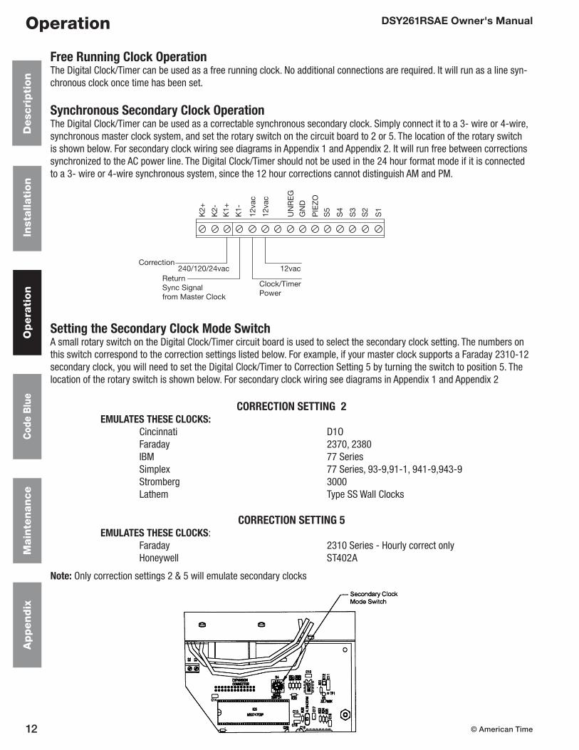
Battery MaintenanceThe Digital Clock/Timer uses a single 9vdc Ni-Cad battery rechargeable via an on board charger. This battery retains the time of day and timer counts when 240vac power is lost. If each in a series of 120vac power losses occur for a similar length of time, the battery can be conditioned to provide only that amount of backup capacity. This phenomenon is called “memory” effect. The Ni-Cad battery’s “memory” can be erased by deeply discharging the battery and recharging it.
It is recommended that the operator remove 120vac power from the Digital Clock/Timer once per year for at least four hours.
System MaintenanceThe Digital Clock/Timer and ATSTCS Control Station have been manufactured for years of dependable, reliable use. However, to assure the reliability of this product, it is recommended that the Digital Clock/Timer be tested at least every six (6) months with the Control Station and Code Blue contact for operation in accordance with wiring configurations used.
WARNINGReplace the battery only with a 9v Ni-Cad battery. Do not replace with a regular (primary) 9v transistor battery (i.e., zinc carbon battery, alkaline battery)! An incompatible battery may leak or explode, causing equipment damage and/or personal injury! If battery must be replaced, contact American Time at 800-328-8996.
© American Time16
DSY261RSAE Owner's ManualA
pp
en
dix
Main
ten
an
ce
Cod
e B
lue
Op
era
tion
Inst
allati
on
Desc
rip
tion
Appendix
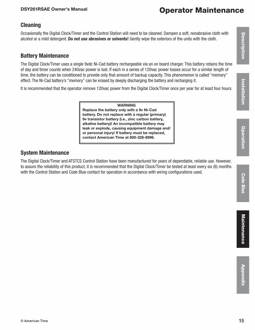
Wiring Diagram for Synchronous Secondary Clock OperationFor use with 3 Wire Clocks
Appendix 1
START/STOP RESET
INCREMENT ENTER
RUN
SET
UP
DOWN
CLOCK
K1- Common
Clock/Timer-120vRun Voltage120vac 35mA
Correct
Digital Clock/Timer
Clock Power120/24vacfrom Previous Clock orMaster Clock
ATSTCS Control Station–Wire per Wiring Diagram onPage 9
Run
Common
Correct
Run
Common
Correct
K1+
To Next Clock

17© American Time
DSY261RSAE Owner's ManualA
pp
en
dix
Main
ten
an
ce
Code B
lueO
pera
tion
Insta
llatio
nD
esc
riptio
nAppendix
Wiring Diagram for Synchronous Secondary Clock OperationFor use with 4 Wire Clocks
Appendix 2
START/STOP RESET
INCREMENT ENTER
RUN
SET
UP
DOWN
CLOCK
K1-
CorrectCommon
Clock/Timer-120vRun Voltage120vac 35mA
Correct
Digital Clock/Timer
From Previous Clock or Master ClockRun PowerPer Clock
Correction Power120/24vac
ATSTCS Control Station–Wire per Wiring Diagram onPage 9
Run
RunCommon
CorrectCommon
Run
RunCommon
CorrectCommon
Correct
K1+
Correct
To Next Clock
© American Time18
DSY261RSAE Owner's ManualA
pp
en
dix
Main
ten
an
ce
Cod
e B
lue
Op
era
tion
Inst
allati
on
Desc
rip
tion
Appendix
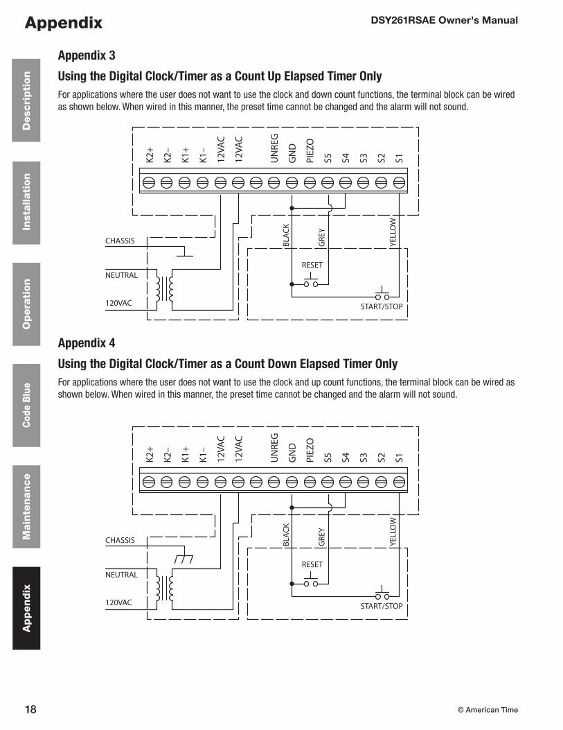
Appendix 3
Using the Digital Clock/Timer as a Count Up Elapsed Timer OnlyFor applications where the user does not want to use the clock and down count functions, the terminal block can be wired as shown below. When wired in this manner, the preset time cannot be changed and the alarm will not sound.
Appendix 4
Using the Digital Clock/Timer as a Count Down Elapsed Timer OnlyFor applications where the user does not want to use the clock and up count functions, the terminal block can be wired as shown below. When wired in this manner, the preset time cannot be changed and the alarm will not sound.
K2+
K2–
K1+
K1–
12VA
C
12VA
C
UN
REG
GN
D
PIEZ
O
S5 S4 S3 S2 S1
BLAC
K
GRE
Y
YELL
OW
CHASSIS
NEUTRAL
120VAC
RESET
START/STOP
K2+
K2–
K1+
K1–
12VA
C
12VA
C
UN
REG
GN
D
PIEZ
O
S5 S4 S3 S2 S1
BLAC
K
GRE
Y
YELL
OW
CHASSIS
NEUTRAL
120VAC
RESET
START/STOP

19© American Time
DSY261RSAE Owner's ManualA
pp
en
dix
Main
ten
an
ce
Code B
lueO
pera
tion
Insta
llatio
nD
esc
riptio
nAppendix
Appendix 5
Operator's Flowchart
To Set Time
UP/CLOCK/DOWN switch in CLOCK position
SET/RUN switch in SET position
Clock display 24Hr or 12Hr
Push INCREMENT to change
Push ENTER
Clock displays flashing hours digits
Push INCREMENT to change
Push ENTER
Clock displays flashing minutes digits
Push INCREMENT to change
Push ENTER
Clock displays flashing seconds digits
Push INCREMENT to change
Push ENTER
Display shows DONE
Place SET/RUN switch in RUN position
To Use as a Clock
Place SET/RUN switch in RUN position
UP/CLOCK/DOWN switch in CLOCK position
Code Blue Operation
SET/RUN switch MUST be in RUN position
To stop and hold code blue time for viewing, press START/STOP
To Reset Clock/Timer to Normal Operation
Place SET/RUN switch momentarily in SET position and return switch to RUN position
To Set UP Counter Preset
UP/CLOCK/DOWN switch in UP position
SET/RUN switch in SET position
Clock displays flashing hours digits
Push INCREMENT to change
Push ENTER
Clock displays flashing minutes digits
Push INCREMENT to change
Push ENTER
Clock displays flashing seconds digits
Push INCREMENT to change
Push ENTER
Display shows DONE
Place SET/RUN switch in RUN position
To Use UP Counter
UP/CLOCK/DOWN switch in UP position
Place SET/RUN switch in RUN position
Place RESET to display 00:00:00
Place START/STOP to Begin
Place START/STOP to Hold
Place START/STOP to begin again
Alarm will sound when preset time is reached
Press RESET to reset counter
To Set DOWN Counter Preset
UP/CLOCK/DOWN switch in DOWN position
SET/RUN switch in SET position
Clock displays flashing hours digits
Push INCREMENT to change
Push ENTER
Clock displays flashing minutes digits
Push INCREMENT to change
Push ENTER
Clock displays flashing seconds digits
Push INCREMENT to change
Push ENTER
Display shows DONE
Place SET/RUN switch in RUN position
To Use DOWN Counter
UP/CLOCK/DOWN switch in DOWN position
Place SET/RUN switch in RUN position
Place RESET to display preset time
Place START/STOP to Begin
Place START/STOP to Hold
Place START/STOP to begin again
Alarm will sound 00:00:00 is reached
Press RESET to reset counter
START/STOP RESET
INCREMENT ENTER
RUN
SET
UP
DOWN
CLOCK
12 3/8”
5 3/8”
3.0”
Digital Clock/Timer


![RESUMED [11.59 am]](https://img.dokumen.tips/doc/110x75/62321f880a46a972821a0a25/resumed-1159-am.jpg)