Embed Size (px)
Citation preview

DSPower 3Uninterruptible Power Supply
10Kva 160KvaUser Manual
MT DSPower 3 Rev.00 pag. 1

SUMMARY:
SAFETY
STORAGE
UPS Description
PFC INVERTER Static switch Battery Control logic
Electrical connection
Electrical protection AC input ByPass Battery RDC
Input output battery connections
External battery box connection
SWITCH Input switch Reserve Switch Manual ByPass switch Output switch Battery Fuse
UPS START UP INSTRUCTIONS
UPS SHUT DOWN INSTRUCTION
INSTRUCTIONS TO SWITICH THE UPS IN MANUAL BYPASS MODE
INSTRUCTIONS TO ETURN UPS IN NORMAL MODE
REMOTE CONTROL AND COMUNICATION POT Free contacts communication port E.P.O. RS232 - RS485 Communication port USB communication port Software
DISPLAY Led Navigation switch menu Menu navigation Measure menu, Voltage Measure menu, Current Battery menu Alarm menu Service menu Parameter menu Relays menu
MT DSPower 3 Rev.00 pag. 2

TECHNICAL CHARATTERISTICS
We would like take the opportunity to thank you to have been choosing our product.ACS is a company whose focus is to project an manufactured system for electrical conversion energy.Our products are This converter UPS has been designed and manufactured according to the highest quality standards, in order to provide the operating characteristics of reliability and durability at the highest levels.
Attention:Please consider this manual includes important information for your safety, installation procedure, technical information, and information to solve any ups issues.This manual contains all needed information to safety use ups, it must be maintained carefully and used only by the technical personal who take care of ups.Furthermore all operations on the ups, for safety reason, have to be taken only by qualified personnel instructed to operate on high voltage system.
SAFETY
Before start to use ups, please ensure that ground wire is connected , terminal marked with GROUND, with yellow/green colour.
Be informed that ups must not be used if there is no ground wire connection.
UPS has to be used only if front door and lateral cover are close..Any operation must be done when the ups is open or with the supplied circuits accessible..Whenever maintenance operations are needed to open the ups front door and the lateral cover please ensure to follow step by step manual bypass instructions; open all circuit breakers in the ups and in the external battery box.Verify with a multimeter there are no voltages on the input output and battery terminal on the ups and external battery box.
When you disconnect the main supply and the batteries, please wait 10 minutes before do any action on the ups, because in the ups circuits may still be stored dangerous voltages.
If necessary to replace the fuses, please ensure that they have the same capacity , and the same technical charatteristic.
Batteries must be replaced only by qualified and authorized personnel.Exhausted batteries has to be provided to specialized consortium, contact the producer to get all relevant information.Batteries are toxic products and their storage is controlled by local law.
CE certificationUPS is complying to CE rules and it is certified by:
LV Directive 2006/95/EC.- EMC Directive 2004/108/EC.
STORAGE
If the ups is not installed immediately, it must be stored in the original packaging protected by water and dust.If batteries are inside the ups, those must be charged every 6 months for 8 hours each.We suggest to store the ups in places with temperature between:
+10° to 30°C (+50° e 86°F).
Installation Instructions
Ups and batteries cabinet have been designed and made to be installed internally.In order to install correctly the ups please consider the following information:
MT DSPower 3 Rev.00 pag. 3

Avoid dust ambient The floor where the ups and batteries cabinet are placed must be supported the totally weight. Avoid to install ups and batteries cabinet in restricted places, to do not have problems during maintenance
activities. The relative humidity has not to be higher than 95%. Avoid to install ups to direct contact with warm air. When the ups is working, room temperature should be between 0 40 degreed for 8 hours, and average
temperature per day should be of 35 degrees max. Battery correct temperature is between 20 25 degrees max. For correct ups ventilation the place must be able to exchange of air equal or greater than the ones produced by
the ups and batteries.
Preliminary Operation
Packaging control
Upon receipt of the UPS and any battery cabinets, check the conditions of, if they had occurred the damage during shipping please contact the manufacturer. If everything appears to be in order to proceed with the unpacking and placement of the devices using the utmost care and attention. With the ups also need to get the instruction manual and shut down software (optional), serial cable(otional), snmp agent (optional).
The ups is packed with a carton box cover and placed over a wooden pallet to be moved during transport and during placement. Make use of a forklift to handle ups.
MT DSPower 3 Rev.00 pag. 4

UPS placement
Place the UPS at least 60cm away from walls around, remember that the air enters from the front and below the ups and exits from the rear. Do not obstruct in any way the air inlets and outlets. The power cables I / O coming from the base of the front, and all the switches are opening the front door. Depending on the power of the UPS batteries may be contained inside the ups. The removal of batteries inside the ups can be removed by removing the lateral side shields. Sufficient distance from the walls in such a way as to be able to perform any maintenance. The cabinet ups and battery cabinets, equipped with wheels or legs that facilitate movement, remove from the pallet and move the ups by a forklift.
UPS DESCRIPTIONThe UPS is a static electric machine that through the conversion of energy drawn from the batteries connected to it, The ups supply the load when the input line is present or not. The ups is composed of:
Input PFC Inverter Statc ByPass Battery Control Logic
The picture show the schematic block of ups.
Input PFC
The PFC input is an AC / DC converter that converts the input AC voltage to DC voltage which is used to supply the inverter and to charge the batteries. The PFC (Power Factor Corrector) allows you to present to the mains load ups whatever it is, as a resistive load, absorbing energy with a cosPHI close to 1, normally 0.99, reduces the harmonics injected into the power line by capacitive and inductive load and by non linear load. The IGBT and the high performance DSP used in the PFC, permit to obtain the very high efficiency. The start up of the PFC on the input line is controlled by a ramp of charge in such a way as to keep the very low inrush current .
Inverter
The inverter will convert the DC voltage of the PFC and the battery into AC voltage which is then supplied to the loads connected to the UPS.
The waveform of the output voltage is a sine wave with a very low distortion, less than 3%, perfectly stabilized in frequency and voltage.
MT DSPower 3 Rev.00 pag. 5
The inverter has no output transformer, transformerless, and uses a three-phase IGBT bridge which ensures reduced dimensions and very high efficiency.
Static switch
The ByPass automatically switches to the reserve line to line inverter without interruption transfer time = 0 The switching of the two lines occurs when they are in perfect synchronism always ensuring a correct supply to the load
Battery
The UPS batteries feed the loads connected to the UPS in case of lack of the electricity network, by ensuring a more or less long time back to the system according to their capacity. The batteries are maintenance free dry type. During the charging , the PFC control the temperature and changing the charging curve as the temperature changes, ensuring a perfect charge to the batteries and a long life
Control logic
The operation of the UPS is fully digital, including the generation of all signals required to operate the inverter and Pfc.To do this each PFC and inverter control board, equipped with two performant DSP (Digital Signal Processor), which control all the variables in a very short time alarms and events that occur during the operation of the UPS. The use of DSP also allows you to remain unchanged over time, the technical characteristics of ups while always ensuring the calibration characteristics arranged in testing phase.
Electrical Connection
Protection
Below are show the data for dimensioning the UPS input and output protection.
10 20 30 40 50 60 80 100INPUTImax* [A] 20 40 60 80 100 120 160 200
BYPASSImax [A] 20 40 60 80 100 120 160 200
OUTPUTRated Current [A] 20 40 60 80 100 120 180 200
BATTERYCurrent 16 32 60 80 100 120 180 200
Table1
* The maximum current (Imax), is calculated using the minimum input voltage and maximum output current and the batteries completely discharged.
MT DSPower 3 Rev.00 pag. 6

AC InputIs recommended to be installed in input and output of the UPS devices for overcurrent protection, these protections are realized through the use of fuses or circuit breakers referring to the above table.
BYPASSIf the ByPass line is separate from input line, provide to install an overcurrent protection.
BATTERYAttention, the battery fuses are connect directly on the DC voltage circuits at the time of replacement be sure to replace fuses equal to those assembled at the factory Each and every battery box has the fuses, be sure that the fuses that are mounted in external battery cabinets must be mounted on the cabinet itself
RDCA DRC device (Residual Current Detector), must be installed in input of the UPS. The differential switch in input of the UPS must have the following characteristics:
Sensibility 500ma Class A o B Delay major or equal 0,1sec.
Input output and battery connection
Warning, the following operations must be performed by qualified personnel. Before performing any type of electrical connection terminals to connect the grounding.
Before doing anything, make sure that the UPS is completely isolated from the power supply from the load and especially the batteries, so all circuit breakers and fuses on board ups and in any battery cabinets must be open. Check that the switches: Main line, Reserve line, Battery, Output, and ByPass, are open, and that switches on all battery cabinets are open, then use a multimeter to make sure that there are no dangerous voltages at the terminals of 'ups, battery cabinet and connecting cables
Below are show the ups electrical connections in various configurations. The ups, to be connected to the mains and to the loads to be supply, has a terminal block which is located in the bottom by opening the front door. Being the ups with separate entrance to the reserve is normally supplied with the reserve and the main line connected to each other through the cables, if you wanted to use a separate network of reserves will be sufficient to remove these cables and connect the reserve line. Before proceeding with the link ups, make sure that there are no tensions in the electrical system and all the organs of switching and protection are able to withstand the continuous current required by the UPS. To know the current values refer to the table Table1.
MT DSPower 3 Rev.00 pag. 7

Before starting any operation connect the ground wire
Also check :
Ensure that the voltage and frequency value are correspondent with the value mark on the ups label Check that the ground connection of the system, is complies with the IEC standard norm.
Install in input and output of the ups the quadripole and or bipolar switch having the following specifications:
Capacity equal to or greater than the capacity indicated on the identify ups label or refer to the current table Characteristics comply with CEI norm or regulations at the installation site, with curve C
In the figure shows the input/output terminal block which is located by opening the front door of the UPS and removing the metal protection.
MT DSPower 3 Rev.00 pag. 8

In figure shows the connections on the input output terminal block a three-phase three-phase ups with separate reserve.
Wiring diagram for three-phase three-phase UPS with a separate reserve
Note:
1 L 'ups has been designed to work with a three phase line input and neutral. 2 To install protection systems for input and output overcurrent, refer to the table 1 3 In the event that you were to use a power line without the neutral, you must install a transformer in input of the UPS delta / star.
MT DSPower 3 Rev.00 pag. 9

In figure shows the connections on the input output terminal block a three-phase three-phase ups with reserve and input don’t separate.
Wiring diagram for three-phase three-phase UPS with a input line and reserve don’t separate.
Note:
1. The ups has been designed to operate with an input line phase with neutral..2. To install input and output sourge protection refer to the table.3. For use the ups with the power line without neutral, connect in input of the ups an power transformer star
delta4. To use a single input line and reserve line, is sufficient to create a connection between the terminals
Reserve Line and Input Input.
MT DSPower 3 Rev.00 pag. 10

The diagram below shows the connection of the UPS configuration in single phase / single phase line to a separate reserve.
Wiring diagram of single phase ups with separate reserve line
MT DSPower 3 Rev.00 pag. 11

The diagram below shows the connection of the UPS single phase/single phase with no separate reserve line
UPS single phase diagram without separate reserve line
MT DSPower 3 Rev.00 pag. 12

The diagram below shows the connection in the UPS three mono phase configuration with separate reserve line.
Wiring diagram three phase mono phase ups with separate reserve line.
Note:
1. The ups has been designed to operate with an input line phase with neutral..2. To install input and output surge protection refer to the table.3. For use the ups with the power line without neutral, connect in input of the ups an power transformer star
delta4. To use a single input line and reserve line, is sufficient to create a connection between the terminals
Reserve Line and Input Input.
MT DSPower 3 Rev.00 pag. 13

The diagram below shows the connection in the UPS three/mono phase with no separate reserve line.
Wiring diagram Three/mono phase ups without separate reserve line.
Note:
1. The ups has been designed to operate with an input line phase with neutral..2. To install input and output surge protection refer to the table.3. For use the ups with the power line without neutral, connect in input of the ups an power trasformer star
delta4. To use a single input line and reserve line, is sufficient to create a connection between the terminals
Reserve Line and Input .
MT DSPower 3 Rev.00 pag. 14

The figure shows the mono phase/three phase UPS input/output terminal block
The figure shows the wiring diagram of the UPS in single-phase three-phase configuration
Note that the reserve line is not present in this configuration, being the single-phase input and three phase output generated only by the inverter
MT DSPower 3 Rev.00 pag. 15

The figure shows the UPS electrical connection in converter configuration.
The figure shows the input output terminal block for the inverter converter. Note, in this configuartion the reserve line is not connected, as the frequency of input / output and the input / output voltage may be different. If required comes converter / ups that combines the typical functions of the converter with the ability to supply the loads in the absence of current line
To use the configuration E.P.S. (Emergency Power Supply) you can refer to the electrical schematics and connection of the converter.
MT DSPower 3 Rev.00 pag. 16

External battery connection
Caution, the external battery have a very high and dangerous voltage.All operation must be performed by qualified personell.
To increase the back up time of ups you can connect the external battery cabinets. The figure shows the connection diagram of external battery cabinets.
All external battery cabinets (optional) are equipped with fuses or circuit breakers for protection, which can be found by opening the front door of the cabinet. The batteries have a very high nominal voltage , you should exercise extreme caution when connecting the battery to the UPS box. The maximum capacity of the batteries is determined by the characteristics of the PFC input. Refer to the technical manual to determine this value. An incorrect battery capacity setting, could create damage to the batteries.
MT DSPower 3 Rev.00 pag. 17

Switches
Opening the front door of the UPS you have access to the switches / disconnectors. The figure shows the switches in the ups from 10 up 60va.
Input switch
The input switch disconnects the input stage PFC from the main line. It is also used as a power switch with circuit line reserve, at the time of closing the control logic are powered ups and prepares for the start of the procedure, is so fed activating the PFC that feeds the inverter stage.
Reserve switch
The Reserve Switch disconnect the power from static bypass. The reserve line is check from inverter control logic to determine the frequency of operation, the phase sequence , and is the line which is taken as a reference for the synchronism over to power the load pending that the inverter becomes active.
Manual ByPass switch
The manual bypass switch is used when is necessary to completely isolate the UPS from the mains. When the switch is closed, the voltage present on the reserve line is directly connect to the output, the inverter control logic force the static switch to reserve line , and in the display front panel the manual bypass led is on. When you reopen the switch back the UPS to operate as normal.
Warning, before closing the Manual ByPass switch ,carefully read the procedure manual ByPass described in this manual, the closing of Manual ByPass switch without having complied with the proper procedure involves damage to the inverter.
Output switch
The output switch connects the UPS to the loads connected to it. When this switch is open, the loads are fully insulated and will be supplied only in the case where the switch is closed Manual ByPass.
MT DSPower 3 Rev.00 pag. 18

Battery fuse
The battery fuses connect the battery (inside the ups) with the inverter stage. If this switch remains open during normal operation, the batteries are not recharged, in the event that occurs an interruption of the input line the inverter don’t have back up time.
Start UPSOnce all ups connections are made respecting the instructions in this user manual, you can turn on the ups. Before closing any switches of the UPS, make sure that all switches are open , then you can power up the power supply line.
To turn on the UPS as follows:
Close the Input switch The control logic is powered, the display and the fans will come on the pfc is activated and begins to supply power to the inverter, which continues to remain switched off.
Close the switch Reserve Line The logic inverter detects the frequency of the line and sets it automatically checks if the phase sequence is correct and then turn on the inverter,
Close the output switch The load is powered through the reserve line .
Close the battery fuses. After the LED line on the display and the LED inverter will be turned on you can close the battery fuses. At this time the UPS will operate properly in the event of a blackout and power to the load without interruption
If you want to stop at any time the ignition process is sufficient to open all switches will be canceled immediately and the power ups.
Close the battery fuses only and exclusively when the ups is started and when in the display panel the led inverter and the led line are on.
Switch off the upsTo shut down the UPS, proceed as follows:
Turn off the loads connected to the UPS Open the output switch Open the battery fuses Open reserve switch Open Input Line switch
MT DSPower 3 Rev.00 pag. 19

Manual ByPass Procedure
WarningFollow this procedure.Not observe this procedure may cause serious damage to the UPS
The manual ByPass connects directly and mechanically without any control the input with the output of the UPS. This if not done correctly can result in serious damage to the inverter section. It is necessary to activate the Manual ByPass when you have to perform the normal or extraordinary maintenance that provide total isolation from any potential ups
To activate the Manual ByPass proceeds as described below:
Through the display front panel , force the ups in static bypass mode, when the the load is supplied by the reserve line and the led bypass is on, and the inverter is off, refer to parameter section.
Remove the Manual ByPass switch block and close the switch. On the display panel the Manual ByPass led is on. Now the load is supplied by the reserve line trough the Manual By Pass switch. Open the switch Line, Reserve Line , Output and the battery fuses.
Open also the battery fuses in the external battery box.In this condition, the UPS will turn off after a few seconds and the load will continue to be fed. In the event that it is necessary to intervene within ups remember to wait at least 10 minutes after turning off as in it could be very dangerous voltages accumulated during
Manual ByPass to normal operationTo turn off the Manual ByPass, proceed as follows
Close the input switch, now the control logic are activated along with the display and fan, the LED line is activated Close the Reserve switch the ByPass Led and after the inverter Led are on. Close Output switch Wait until the Inverter LED turns on and then closing the battery fuses Open the Manual ByPass switch , place the bloc in the manual ByPass switch, the Led Manual ByPass in the
front panel turn off.Now the UPS working in normal operation.
MT DSPower 3 Rev.00 pag. 20

Remote controlThe UPS is equipped with communication ports for remote control.
Opening the front door you have access to the UPS communication ports.There are:
RS232 port DB9 female RS485 port 9Pin male USB port Free contact port
Front view communication port
A: free contact port terminal blocB: Emergency Power Off (EPO)C:RS232 communication port DB9 femaleD:RS485 communication port DB9 maleE:USB port
Free contact port and EPO connector RS232 and RS 485 Port
Free contact port
The UPS has a series of relays (potential free contacts), which can be used to communicate the various states of alarm and operation. Through the display located on the front door, you can configure these relays, or associate them with a state of operation or alarm ups. Also through the display you can also set the status of each relay as normally open (NO) or normally closed (NC). The relay contacts can withstand a current of 10A at 250Vac
MT DSPower 3 Rev.00 pag. 21

E.P.O. Emergency Power Off
The EPO command, is a command that immediately and completely inhibits the ups, when you open the EPO contact , the ups immediately open the static switch and the load is not supplied also if the ups working in battery mode. This type of command is a memory, that when this occurs it is necessary to turn off and on the ups to restore normal operation
RS232 RS485 Communication Port
With the serial communication port Rs232 and Rs485, is possible trough a dedicate software UPSilon, monitored the ups, also is possible command the ups in certain functions. Through the RS232, it is also possible to connect a converter snmp (optional), to connect the UPS to the LAN TCP IP, making it visible on wide area network via the Internet.
USB port
All DSPower UPS, have a USB communication port .
Monitoring Software
Through the RS232 , RS485 communication ports and USB, using a dedicated software, you can monitor and program certain functions of the UPS. You can also program the orderly shut down of the systems connected to the UPS with different operating systems such as Windows, Linux, etc.. It 'also available, as an option, a snmp adapter that lets you connect the UPS to a wide area network, allowing control by a computer anywhere where there is an internet network.
MT DSPower 3 Rev.00 pag. 22

Display
All DSPower UPS have a 320x240 graphic display, where you can view all states of operation, alarm and measures of various parameter on the UPS. Also through the display, you can change the operating mode of the UPS, set different parameters and program the free contacts relay.
The Picture show the start page of the display
After power up, the display will automatically be placed on the running page, where you can see the ups states ups.
MT DSPower 3 Rev.00 pag. 23

MT DSPower 3 Rev.00 pag. 24

The figure shows the Running page of the display
This page is activated automatically after about a minute without any operator presses any key, and show the operating status and any alarms (through the alarm icon), in the UPS. The 5 buttons in the display page are activated by pressing the navigation keys (UP, Down, Right, Left) on the front panel of the UPS.
The figure shows the LEDs on the front panel of the UPS, which have the function of giving an immediate image of the operating status of the UPS.
Led Line:
The LED line is activated when the main input of the UPS is inside the input voltage range, for example 230Vac (400Vac three-phase) +/- 20%, and the input frequency is included in the +/- 10% of the frequency of operation.
Led Inv. On
The LED Inv. is activated when the inverter turns on and is ready to supply the loads.
MT DSPower 3 Rev.00 pag. 25

Battery On LED
The On Battery LED is activated when the UPS take the power from the batteries, this could happen even if the line is present but is not within the correct tolerance range of operation of the UPS. When this LED will turn on the PFC does not charge the batteries that consequently begin to discharge.
ByPass LED
ByPass LED turn on when the Static ByPass switch is active. In this condition the load is powered by the reserve line that in the case of Black Out the load is not supplied. The LED is on when the ups is in this condition:
Starting procedure Overload Overtemperature Fault Short Circuit UPS switch in ByPass by the control panel Manual ByPass active
Fault Led
The Fault LED is on when the UPS has occurred within a state of emergency or a fault will also turn on when the input voltage is out of tolerance or in black out condition. The fault LED will turn off automatically when the condition that caused the fault is no longer present.
Buzzer
In addition to visual signals, the UPS is equipped with an audible alarm (buzzer), which is activated in different ways for time and duration, depending on the alarm that must report. The buzzer can be silenced through the display
Navigation Key
On the front of the UPS are also present the keys to navigate in the various ups menus.
The figure shows the buttons on the front of the UPS
Enter
Press enter to confirm your choice .
UP
With the UP button scrolls up the display cursor, which highlights a key or a value that at that time you can change or select.
Down Button
Con il tasto Down si scorre verso il basso il cursore del display, il quale evidenzia un tasto o un valore che in quel momento è possibile modificare o selezionare.
Right Button
MT DSPower 3 Rev.00 pag. 26

With the Right button to scroll the cursor to the right of the display, which highlights a key or a value that at that time you can change or select.
Left Button
With the Left button to scroll the cursor to the left of the display, which highlights a key or a value that at that time you can change or select.
Menù navigation
The following describes the procedures to be able to move through the display menus and setting of the display. From the home page with the navigation keys left or right you move up to one of the buttons to flash on the display. When a button is selected, the same flashes as in the figure below
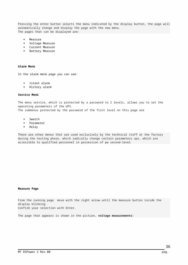
Pressing the enter button selects the menu indicated by the display button, the page will automatically change and display the page with the new menu. The pages that can be displayed are:
Measure Voltage Measure Current Measure Battery Measure
Alarm Menù
In the alarm menù page you can see:
Istant alarm History alarm
Service Menù
The menu service, which is protected by a password to 2 levels, allows you to set the operating parameters of the UPS. The submenus protected by the password of the first level on this page are
Swatch Parameter Relay
There are other menus that are used exclusively by the technical staff at the factory during the testing phase, which radically change certain parameters ups, which are accessible to qualified personnel in possession of pw second-level
Measure Page
MT DSPower 3 Rev.00 pag. 27

From the running page move with the right arrow until the measure button inside the display blinking. Confirm your selection with Enter.
The page that appears is shown in the picture, voltage measurements:
This page displays all of the input output voltage value of the UPS.
PFCThe values shown in the PFC table regarding the ups input voltage . The voltage values are relative to the voltage from phase to neutral and also from phase to phase.
InverterThe values shown in the INVERTER table regarding the Inverter voltage . The voltage values are relative to the voltage from phase to neutral and also from phase to phase
ReserveThe values shown in the Reserve table regarding the ups Reserve voltage . The voltage values are relative to the voltage from phase to neutral and also from phase to phase
From Voltage measurements page push the right button and select Current, Current button in the display flashing, confirm with enter button, now you are in the for current measurements.
Current Measure
MT DSPower 3 Rev.00 pag. 28

This page shows the current value of the load , and the temperature of Inverter and PFC IGBT Power module.
Rms current value
The current of the loadis show n this page with 3 different way:
Bar graph with the percentage of the load ( the 100% is the max current of ups) Rms value, this value is in amper Kva value:
In addition to this value, the display show also the cosPhi value. All measurements are performed for each phase.
Have also highlighted the temperature of the inverter power modules and Pfc. These temperatures are then processed by the control logic for deciding the speed of the fans and algorithms of the switching of the IGBT modules.
MT DSPower 3 Rev.00 pag. 29

Battery measurement
From the current measure page , with the right button select the Battery, when this button inside the display flashing push enter button and confirm.On the display appear the picture below.
The DSPower ups are engineered for working a double VDC bus, we have a positive and negative voltages refer to 0, neutral.
For each series of battery are show:
Charging and discharging current Battery voltage
Battery temperature is displayed in degrees, this temperature value is used by the control logic PFC to modify the charging method, floating or boost charge, in order to have the battery everytime at 100% and assure a long life at the battery.
.
In this page is possible to perform the battery test.
MT DSPower 3 Rev.00 pag. 30

Alarm
From running page move with right button until the Alarm button in the display flashing, confirm with the enter button.The display show the page below.
On this page you can display two types of alarms, the alarms on the UPS at the time of opening the page alarms, and alarms that are stored during operation. The alarms stored are 100, when the memory is full the last old alarm is canceled. The up and down buttons, scrolls through the pages of the historic. When you enter in the alarm page, the page that appears regards the most recent alarms. Each displayed alarm is structured in this way:
Date, hour Alarm description What kind of board have the alarm
The stored alarms can not be erased by the operator thus avoiding the loss of important information for those who must perform maintenance.
MT DSPower 3 Rev.00 pag. 31

Service
From running page move with right button until the service button in the display flashing, confirm with the enter button.The display show the page below.
Swatch
From Service page move with right button until the service swatch in the display flashing, confirm with the enter button.
With the left and right arrow, select the variable to be setting, (Hours Minute, Years….), and with the UP / DOWN setting the desired value, press the Enter key and repeat this process with all the other values to adjust. When the operation is completed, confirm with the save button in the display, push enter to confirm. The display will show the message data backup performed, or if the operation is not successful.
MT DSPower 3 Rev.00 pag. 32

Parameter
From running page move with right button until the Parameter button in the display flashing, confirm with the enter button.Through this page you can set the setting parameters and modes of operation of the 'ups
The display show the page below..
Output voltage
Is possible adjust the output voltage of the inverter within the +/- 10% of rated voltage. When the value of the output voltage is selected, the value flashing, now with the up and down button is possible change the value. Press the ENTER key to confirm , and immediately the inverter adjust the value of the output voltage.The output voltage is the same for all the three phase..
MT DSPower 3 Rev.00 pag. 33

Battery Capacity
Warning: changing this parameter without first contacting the manufacturer of the UPS, it can cause serious damage to the batteries, do not change it unless you know the effects, .
Is possible to change the back time of the ups mounting of additional optional external battery cabinets. Now is important to change the battery capacity inside the pfc control board, in order to recharge the battery in the right way.When you change the capacity of the battery, the recharge systems change the recharge curve and recharge current, if the value of the battery is wrong, is possible to have the serious damages’ in the battery.
From the page parameter move until the battery capacity value flashing.With the up and down arrow button adjust the value and confirm with the enter button.At this point the capacity of the battery is changed. Operation Mode
The UPS has the possibility to work in different ways:::
On Line, provides maximum protection to the loads connected to it, the inverter always supplies the load and the mains power is used to charge the batteries and to provide the DC voltage to the inverter
.
Off line, the load is supplied by the reserve line, the inverter is always on in the proper voltage and frequency and synchronized with the reserve line, when we have a power failure, the load is switched on the inverter which will supply until exhaustion the batteries.
EPS: Emergency Power Supply , the load is connected to the static switch but is not powered, when we have a power failure, the inverter supplies the load until the batteries are discharged. Is possible to set in the EPS the function of delay in switching off, this delay time is set by the display that keeps active the inverter even after the return of the line to allow the time necessary for certain types of lamps that light up slowly, when the delay time is finish the EPS turn off the output..
Converter: with this particular function, you can use the UPS as voltage converter or frequency converter, the frequency and the output voltage can be different from that of entry, with regard to the frequency converter there are 3 selectable frequencies, 50, 60, 400H
MT DSPower 3 Rev.00 pag. 34

RELAY
From parameter page move with right button until the Relay button in the display flashing, confirm with the enter button.Through this page you can set the setting the relè in the communication board.The display show the page below
The UPS has the possibility to set six different relays with different functions related to a state of alarm or operation of the UPS. For each relay will see a page like the one shown in the figure, where the top center is highlighted and the relay on the left are the states of alarm or operation. With the UP / DOWN select the type of alarm and operational status of the relay, press ENTER to confirm. With the arrow Right Left is changed by selecting the relay you want to program and press ENTER to confirm your choice. The page will change and the number will appear at the top of the relay selected. You choose the alarm or function to be linked to the relay and then change again relay. At the top right is a button labeled NC Selecting changing the status of the contact with the relay at rest, ie normally open or normally closed. This function can be selected independently for each relay. Selecting PARAMETERS then returns to the page PARAMETERS
MT DSPower 3 Rev.00 pag. 35
TECHNICAL SPECIFICATION
UPS 10 20 30 40 60 80 100POTENZA Kva Kw
108
2016
3024
4032
6048
8064
10080
Leakage Current 500maAmbient Temperature 0÷ +40˚CMax temperature 8hours on 24hours
+40˚C
Max temperature for 24hours +35˚CHumidity relative 20÷90%Ventilation Forced with speed fan controlMax altitude 1000m at max power (-1% for any 100 m over 1000m), max 4000mNoise at 1m 65dbConnection cables From the bottom frontCommunication port Standard Rs232, RS485, USBOptional SNMP AGENTFree contact 6 relay 250Vac 4A adjustableNormative EN 6204-1-2
EN5091-2 IEC62040-2
INPUTPFC 10 20 30 40 60 80 100Nominal Voltage 400Vac 3Ph+NInput range -20% +20% Vnom.Nominal Frequency 50/60Hz auto setFrequency range 45/65HzInput currentInserction time 60secondiStandard Battery Pb Noise at 1 metro 65dbBattery cell (180)+(180)Nominal Battery voltage 360/360Ripple <1%Stability +-1%Harmonic Distorsion <3%CosPhi@Inom 0.99
INVERTERINVERTER 10 20 30 40 60 80 100Nominal Power KW 8 16 24 32 48 64 80Nominal Voltage 400Vac 3Fase con Neutro SelezionabileNominal Current @ 400Vac 14 29 43 58 86 116 145Nominal Frequency 50/60Hz Output wave form sinusoideOutput Distorsion Linear Non linear Ref 62040-3
<2%<3%
Static stability +-1%Frequency stability Free running With Line
+- 0.005%+-1%
Frequency sweep sync 1Hz/secOverload 110%x10min,125%x1min,150%x1secI short circuit 1,7 Inx1sec
MT DSPower 3 Rev.00 pag. 36

ByPASSBYPASS 10 20 30 40 60 80 100Nominal Power KW 8 16 24 32 48 64 80Nominal Voltage 400Vac 3Fase con Neutro SelezionabileNominal current @ 400Vac 14 29 43 58 86 116 145Nominal Frequency 50/60Hz Transfer time 0Overload 110%x10min,125%x1min,150%x1sec
SEGNALAZIONILine Failure LED Input Line Fail LEDOn ByPass LEDInverter On LEDUPS on Battery LEDFault LEDManual ByPass LEDLow Battery Acustic with variable frequency Overload AcusticIGBT desaturation Acustic/LED FaultFault AcusticShort circuit AcusticOvertemperature AcusticWrong phase sequence Alarm in the alarm page
Segnalazioni Remote6 adjustable relais by the display panel
MT DSPower 3 Rev.00 pag. 37

MT DSPower 3 Rev.00 pag. 38

MT DSPower 3 Rev.00 pag. 39