Embed Size (px)
Citation preview
Diablo Controls, Inc. Copyright © 2015 Document: DSP50_MAN_A Released: September 28, 2015
Pros Who Know Trust Diablo
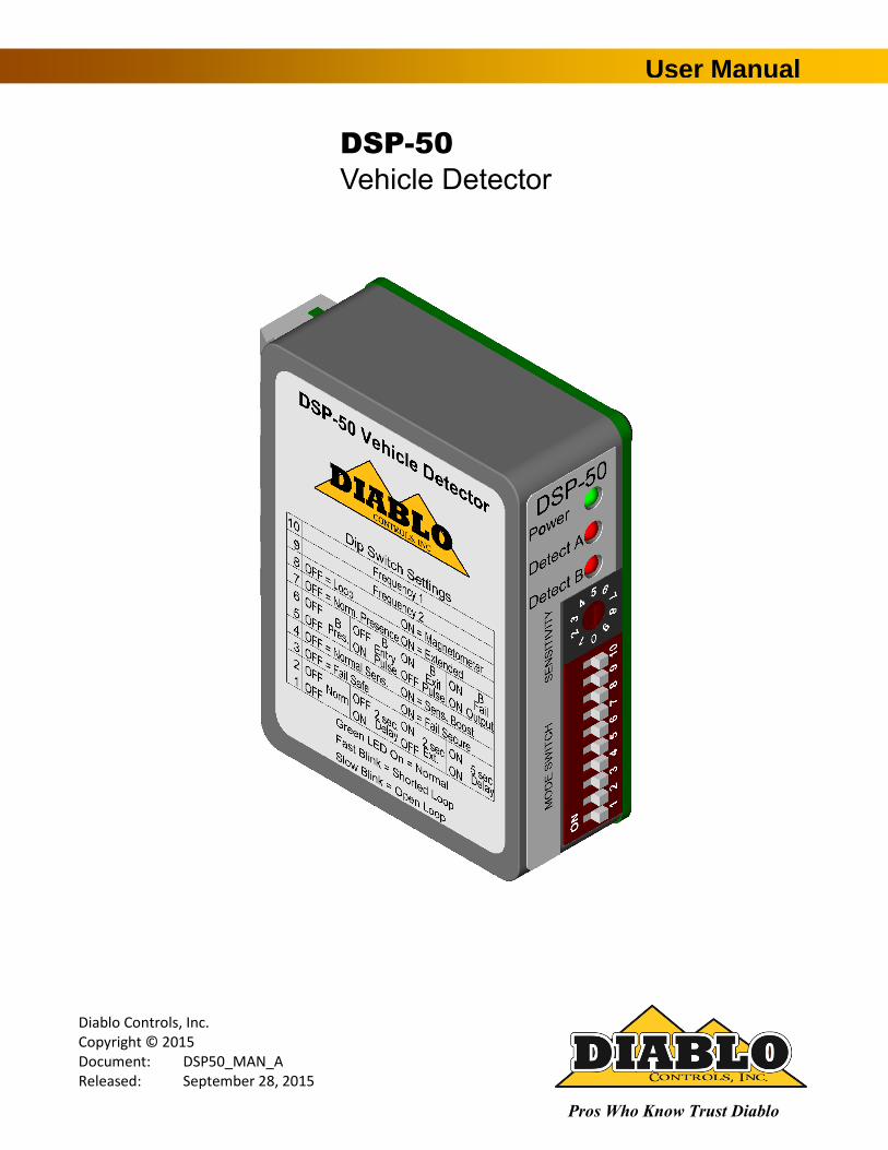
User Manual
DSP-50
Vehicle Detector
DSP-50 User Manual Page 2 of 27 DSP50_MAN_A
1. Contents
Figures .................................................................................................................................................................... 3
2. Introduction ........................................................................................................................................... 4
3. Technical Data ........................................................................................................................................ 5 Functional Data ....................................................................................................................................................... 5 Electrical Data ......................................................................................................................................................... 6 Environmental Data ................................................................................................................................................ 6 Mechanical Data ..................................................................................................................................................... 7
4. Features and Functions ........................................................................................................................... 8 Solid-State Outputs................................................................................................................................................. 8 Detector Reset ........................................................................................................................................................ 8 Presence Detection................................................................................................................................................. 9 Pulse Detection ....................................................................................................................................................... 9 Sensitivity (Rotary Switch) .................................................................................................................................... 10 Frequency (DIP Switches 9 and 10) ...................................................................................................................... 11 Loop / Magnetometer (DIP Switch 8) ................................................................................................................... 11 Normal / Extended Presence (DIP Switch 7) ........................................................................................................ 11 Output B Selection (DIP Switches 5 and 6) ........................................................................................................... 12 Normal Sensitivity / Sensitivity Boost (DIP Switch 4) ........................................................................................... 14 Fail-Safe / Fail-Secure (DIP Switch 3) .................................................................................................................... 14 Delay / Extension (DIP Switches 1 and 2) ............................................................................................................. 15 Indicators .............................................................................................................................................................. 16
5. Installation ........................................................................................................................................... 20 Detector Installation ............................................................................................................................................. 20 Loop Installation ................................................................................................................................................... 20
6. Configuration ....................................................................................................................................... 23 Wiring ................................................................................................................................................................... 23
7. Troubleshooting ................................................................................................................................... 24 No Power LED ....................................................................................................................................................... 24 Power LED Flashes Slowly (1 Hz) .......................................................................................................................... 24 Power LED Flashes Quickly (5 Hz) ......................................................................................................................... 24 Power LED Shows Two Quick Flashes Once Every Two Seconds.......................................................................... 25 Detect LED Intermittently Comes On / Stays On Without a Vehicle Present ....................................................... 25 Detect LED Will Not Come On With a Vehicle Present ......................................................................................... 26

DSP-50 User Manual Page 3 of 27 DSP50_MAN_A
Figures
Figure 1: Physical Dimensions ....................................................................................................................................7
Figure 2: Outputs with No Delay or Extension ........................................................................................................ 13
Figure 3: Outputs with Delay ................................................................................................................................... 13
Figure 4: Outputs with Extension ............................................................................................................................ 14
Figure 5: Power LED States ...................................................................................................................................... 17
Figure 6: Detect A LED States .................................................................................................................................. 18
Figure 7: Detect B LED States .................................................................................................................................. 19
Figure 8: Loop Installation ....................................................................................................................................... 22
Figure 9: Saw Cut for Home Run Exit and Chiseled Corner for Home Run Exit ....................................................... 22
DSP-50 User Manual Page 4 of 27 DSP50_MAN_A
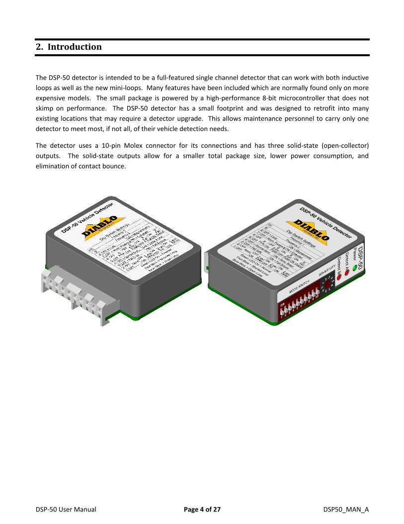
2. Introduction
The DSP-50 detector is intended to be a full-featured single channel detector that can work with both inductive
loops as well as the new mini-loops. Many features have been included which are normally found only on more
expensive models. The small package is powered by a high-performance 8-bit microcontroller that does not
skimp on performance. The DSP-50 detector has a small footprint and was designed to retrofit into many
existing locations that may require a detector upgrade. This allows maintenance personnel to carry only one
detector to meet most, if not all, of their vehicle detection needs.
The detector uses a 10-pin Molex connector for its connections and has three solid-state (open-collector)
outputs. The solid-state outputs allow for a smaller total package size, lower power consumption, and
elimination of contact bounce.
DSP-50 User Manual Page 5 of 27 DSP50_MAN_A
3. Technical Data
Functional Data
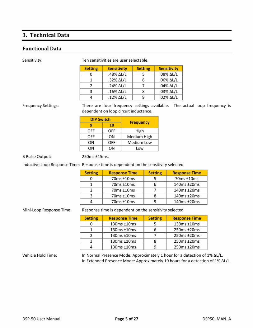
Sensitivity: Ten sensitivities are user selectable.
Setting Sensitivity Setting Sensitivity
0 .48% ΔL/L 5 .08% ΔL/L
1 .32% ΔL/L 6 .06% ΔL/L
2 .24% ΔL/L 7 .04% ΔL/L
3 .16% ΔL/L 8 .03% ΔL/L
4 .12% ΔL/L 9 .02% ΔL/L
Frequency Settings: There are four frequency settings available. The actual loop frequency is dependent on loop circuit inductance.
DIP Switch Frequency
9 10
OFF OFF High
OFF ON Medium High
ON OFF Medium Low
ON ON Low
B Pulse Output: 250ms ±15ms.
Inductive Loop Response Time: Response time is dependent on the sensitivity selected.
Setting Response Time Setting Response Time
0 70ms ±10ms 5 70ms ±10ms
1 70ms ±10ms 6 140ms ±20ms
2 70ms ±10ms 7 140ms ±20ms
3 70ms ±10ms 8 140ms ±20ms
4 70ms ±10ms 9 140ms ±20ms
Mini-Loop Response Time: Response time is dependent on the sensitivity selected.
Setting Response Time Setting Response Time
0 130ms ±10ms 5 130ms ±10ms
1 130ms ±10ms 6 250ms ±20ms
2 130ms ±10ms 7 250ms ±20ms
3 130ms ±10ms 8 250ms ±20ms
4 130ms ±10ms 9 250ms ±20ms
Vehicle Hold Time: In Normal Presence Mode: Approximately 1 hour for a detection of 1% ΔL/L. In Extended Presence Mode: Approximately 19 hours for a detection of 1% ΔL/L.
DSP-50 User Manual Page 6 of 27 DSP50_MAN_A
Electrical Data
Loop Inductance: 20 microhenries to 1500 microhenries (including lead-in inductance). Not all frequency settings are available at inductances below 30 microhenries.
Operating Voltages: One wide range power version:
10 volts to 30 volts DC
Solid State Output Rating: Maximum Output Current: 200 milliamps Maximum Pull-Up Voltage: 40 volts Maximum Voltage Drop Across Active Output: 0.3 volts
Current Draw: 10 volts to 30 volts AC or DC
75 milliamps maximum.
Environmental Data
Operating Temperature: -35°F to 165°F (-37°C to 74°C)
Storage Temperature: -40°F to 176°F (-40°C to 80°C)
Humidity: Up to 95% relative humidity non-condensing
DSP-50 User Manual Page 7 of 27 DSP50_MAN_A
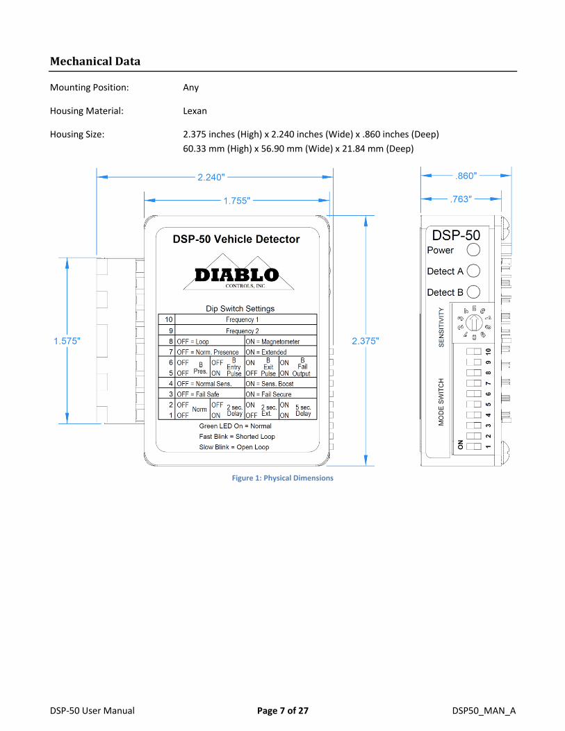
Mechanical Data
Mounting Position: Any
Housing Material: Lexan
Housing Size: 2.375 inches (High) x 2.240 inches (Wide) x .860 inches (Deep)
60.33 mm (High) x 56.90 mm (Wide) x 21.84 mm (Deep)
Figure 1: Physical Dimensions
DSP-50 User Manual Page 8 of 27 DSP50_MAN_A
4. Features and Functions
Solid-State Outputs
The DSP-50 has three solid-state (open-collector) outputs. Solid-state outputs have several advantages over
relay outputs:
Allows for a smaller form factor
Lower power consumption
Outputs do not have to be debounced (relay contact bounce when closing)
Higher reliability due to no moving parts
But they also have their limitations:
Requires that the detector and the operator have the same DC common
Requires a pull-up resistor to function correctly
The output can only be pulled down to DC common (can only sink current)
Limited current switching capability (200 milliamps)
Polarity sensitive (will not work if connected backwards)
With proper engineering these limitations can be easily overcome and the benefits of the solid-state output can
be fully realized. Almost all operators are now designed to share their DC common with external devices and
have built in pull-up resistors on their inputs to facilitate working with solid-state (open-collector) outputs.
These inputs usually require less than 20 milliamps of current sinking capability to be activated.
The polarity issue is handled by the operator if the detector plugs directly in to the operator. If using an adapter
board like the RK-1 or RK-3, the negative side of the output is already connected to DC common. So the output
is simply connected to the desired termination point on the controller and it should all work.
The three outputs that are available on the DSP-50 are Output A, Output B, and Output B Inverted. The
operation of Outputs A & B are discussed in the following sections. Output B Inverted is always the opposite of
Output B. This means that if Output B is active Output B Inverted is not and if Output B is not active then Output
B Inverted will be. Output B Inverted will not be mentioned outside of this section, as it is always the opposite
of Output B.
The easiest way to envision the function of a solid-state (open-collector) output is to think of it as a normally
open relay contact with the relay common connected to DC common. In this way, Output A and Output B can
be envisioned as normally open contact closures and Output B Inverted as a normally closed contact.
Detector Reset
When any of the DIP switches or the 10-position rotary switch is changed, or power is cycled to the detector, the
detector will perform a reset. The reset event will last for two seconds while the detector initiates any changes
and waits for all systems to stabilize.
DSP-50 User Manual Page 9 of 27 DSP50_MAN_A
All three LEDs will turn off for 500 milliseconds at the start of the reset event. After that, the Detect A and
Detect B LEDs will flash according to their fail-safe or fail-secure mode of operation. A flash rate that is the same
as the power LED indicates the output is operating as fail-safe. A much faster flash rate indicates that the output
is operating in the fail-secure mode.
Output A will be active if the detector is in the fail-safe mode. Output B is always fail-secure and will not
activate during a reset.
NOTE: If a vehicle is over the loop during the reset period it will not be detected.
Presence Detection
Presence detection is only available in the loop mode of operation (DIP switch 8 OFF). If the detector is in the
magnetometer mode of operation only pulse on entry operation is available.
While in the loop mode of operation, Output A will always operate in the presence detection mode. Once
activated, the output will remain activated for as long as a vehicle is detected over the loop. After four minutes
of continuous detection, the detector will begin to slowly retune the detector with the goal of tuning out the
vehicle that stalled or parked on the loop over a relatively long time.
The time it takes to complete the retuning process is dependent on the strength of the call being induced by the
vehicle. In the Normal Presence mode usually takes between 15 minutes and about 4 hours. In the Extended
Presence mode the retune process may take over 24 hours. When the retuning process is complete, any loop
area that vehicles can still travel over will still detect the vehicle as expected. Once the vehicle leaves, the
detector will fully recover from the retuning process within 1 second.
Output B can be set to operate in the True Presence mode (not available in the magnetometer mode of
operation). In this mode Output B activates as soon as a vehicle enters the loop and drops as soon as the loop is
no longer occupied. The output will ignore any Delay or Extension features that are currently active.
Pulse Detection
When the magnetometer mode of operation is selected (DIP switch 8 ON), pulse on entry is the only detection
mode of operation and is applied to Output A and Output B. If the detector is in the loop mode of operation
pulse on entry and pulse on exit modes of operation are available.
In the loop mode of operation Output B can be configured for pulse on entry or pulse on exit operation. The
pulse generated by the output will be 250 milliseconds long. Output B will follow any Delay or Extension
features that are currently active. Pulse operation is not available on the A output except in the magnetometer
mode of operation.
In the magnetometer mode of operation Output A and Output B are always configured for pulse on entry
operation. The pulse generated by Output A can be modified using the extension feature. If no extension is
active the pulse will be 250 milliseconds long. If the 2-second extension feature is active the pulse will be 2
seconds long. If the 5-second extension feature is active the pulse will be 5 seconds long. The pulse generated
DSP-50 User Manual Page 10 of 27 DSP50_MAN_A
by Output B will always be 250 milliseconds long. If the 2-second delay feature is active, Output A and Output B
will not pulse until a vehicle has been continually detected for the 2-second delay time.
In Pulse on Entry mode, Output B will pulse when the Output A activates. If the delay feature is enabled, the
pulse will not occur until the delay has timed out and the loop is still occupied. The output will not pulse again
until the loop has been unoccupied and any enabled extension has timed out. After the pulse has been
outputted, the Detect B LED will flicker (a very fast flash that is not at full brightness). This is a visual indication
that the pulse has already been output but the loop is still occupied and no further pulses can be output until
the loop is no longer occupied.
In Pulse on Exit mode, Output B will pulse when Output A deactivates. If one of the extension features is
enabled, the pulse will not occur until the extension has timed out and the loop is still vacant. The output will
not pulse again until the loop has been reoccupied and any enabled delay has timed out. Before the pulse has
been output, the Detect B LED will flicker (a very fast flash that is not at full brightness). This is a visual
indication that a vehicle is being detected and the pulse will be output when the vehicle exits or is eventually
tuned out.
NOTE: In the magnetometer mode of operation the detector will only hold a detection for 2 seconds. Therefore,
if a vehicle stays over the sensor for more than 2 seconds it may generate additional pulses for the same vehicle.
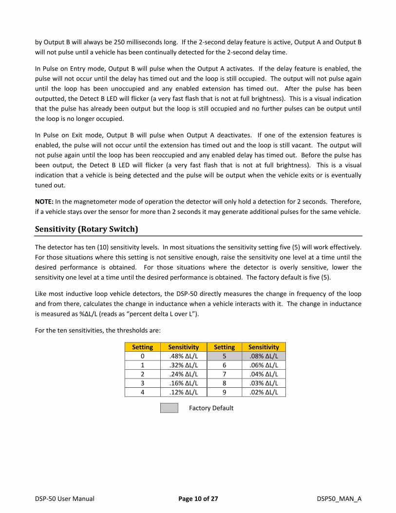
Sensitivity (Rotary Switch)
The detector has ten (10) sensitivity levels. In most situations the sensitivity setting five (5) will work effectively.
For those situations where this setting is not sensitive enough, raise the sensitivity one level at a time until the
desired performance is obtained. For those situations where the detector is overly sensitive, lower the
sensitivity one level at a time until the desired performance is obtained. The factory default is five (5).
Like most inductive loop vehicle detectors, the DSP-50 directly measures the change in frequency of the loop
and from there, calculates the change in inductance when a vehicle interacts with it. The change in inductance
is measured as %ΔL/L (reads as “percent delta L over L”).
For the ten sensitivities, the thresholds are:
Setting Sensitivity Setting Sensitivity
0 .48% ΔL/L 5 .08% ΔL/L
1 .32% ΔL/L 6 .06% ΔL/L
2 .24% ΔL/L 7 .04% ΔL/L
3 .16% ΔL/L 8 .03% ΔL/L
4 .12% ΔL/L 9 .02% ΔL/L
Factory Default
DSP-50 User Manual Page 11 of 27 DSP50_MAN_A
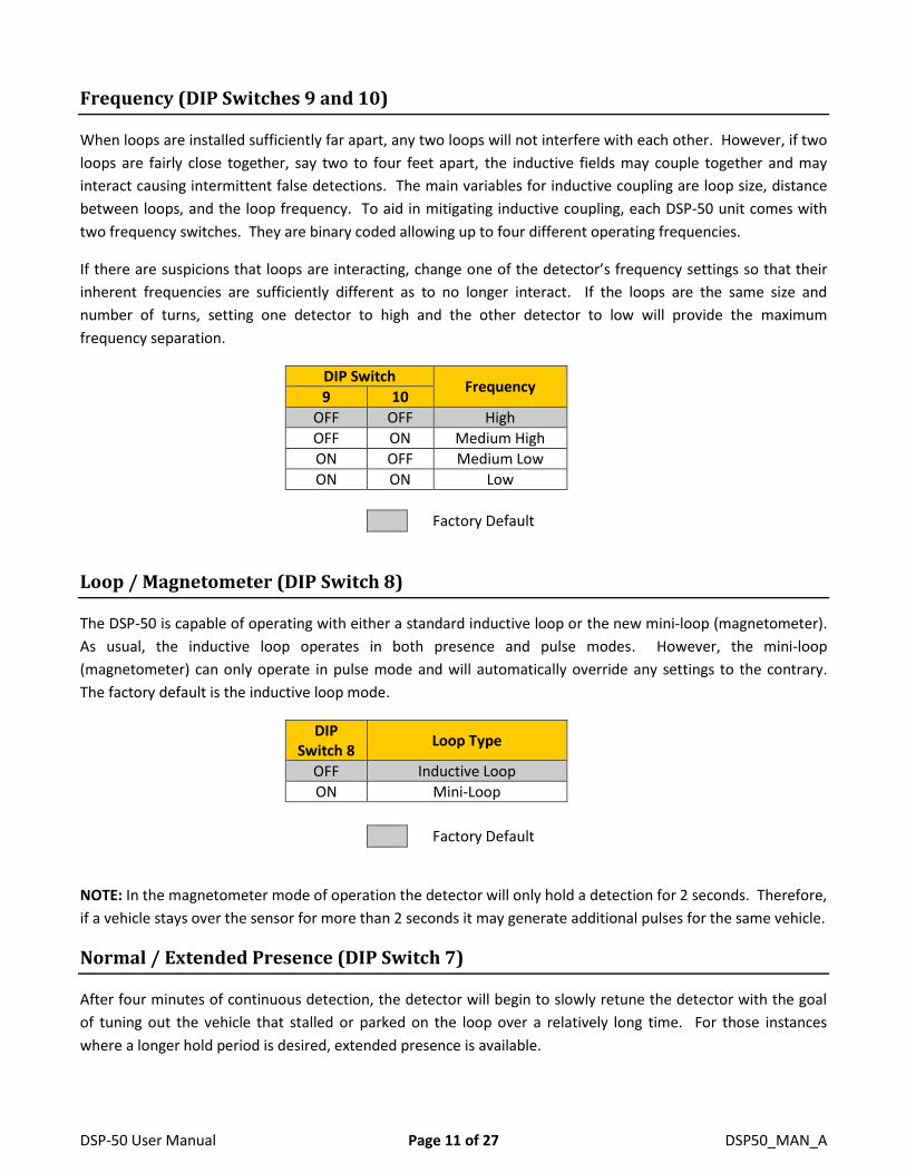
Frequency (DIP Switches 9 and 10)
When loops are installed sufficiently far apart, any two loops will not interfere with each other. However, if two
loops are fairly close together, say two to four feet apart, the inductive fields may couple together and may
interact causing intermittent false detections. The main variables for inductive coupling are loop size, distance
between loops, and the loop frequency. To aid in mitigating inductive coupling, each DSP-50 unit comes with
two frequency switches. They are binary coded allowing up to four different operating frequencies.
If there are suspicions that loops are interacting, change one of the detector’s frequency settings so that their
inherent frequencies are sufficiently different as to no longer interact. If the loops are the same size and
number of turns, setting one detector to high and the other detector to low will provide the maximum
frequency separation.
DIP Switch Frequency
9 10
OFF OFF High
OFF ON Medium High
ON OFF Medium Low
ON ON Low
Factory Default
Loop / Magnetometer (DIP Switch 8)
The DSP-50 is capable of operating with either a standard inductive loop or the new mini-loop (magnetometer).
As usual, the inductive loop operates in both presence and pulse modes. However, the mini-loop
(magnetometer) can only operate in pulse mode and will automatically override any settings to the contrary.
The factory default is the inductive loop mode.
DIP Switch 8
Loop Type
OFF Inductive Loop
ON Mini-Loop
Factory Default
NOTE: In the magnetometer mode of operation the detector will only hold a detection for 2 seconds. Therefore,
if a vehicle stays over the sensor for more than 2 seconds it may generate additional pulses for the same vehicle.
Normal / Extended Presence (DIP Switch 7)
After four minutes of continuous detection, the detector will begin to slowly retune the detector with the goal
of tuning out the vehicle that stalled or parked on the loop over a relatively long time. For those instances
where a longer hold period is desired, extended presence is available.
DSP-50 User Manual Page 12 of 27 DSP50_MAN_A
The time it takes to complete the retuning process is dependent on the strength of the call being induced by the
vehicle. In the Normal Presence mode (DIP switch 7 off) this usually takes between 15 minutes and about 4
hours. In the Extended Presence mode (DIP switch 7 on) the retune process may take over 24 hours. This is
quite a long time, but it isn’t infinite. The DSP-50 does not have infinite presence.
When the retuning process is complete, any loop area that vehicles can still travel over will still detect the
vehicle as expected. Once the vehicle leaves, the detector will fully recover from the retuning process within 1
second.
DIP Switch 7
Presence Time
OFF Normal Hold Time
ON Extended Presence
Factory Default
Output B Selection (DIP Switches 5 and 6)
Output B can be programmed to operate in one of four different modes that are selected using DIP switches 5
and 6. The available modes are modified by the loop / magnetometer operation mode selected. The following
table identifies the modes available in each of the operating modes:
DIP Switch Output B Mode of Operation
5 6 Loop (DIP switch 8 off) Magnetometer (DIP switch 8 on)
OFF OFF True Presence Pulse on Entry
OFF ON Pulse on Entry Pulse on Entry
ON OFF Pulse on Exit Pulse on Entry
ON ON Fail Fail
Factory Default
True Presence: Output B will be activated whenever a vehicle is present over the loop detection area. Output A
can be modified by the delay / extension timing settings. Output B will not use these timing settings. For
example, if 2 seconds of delay is set, Output B will activate as soon as the vehicle is detected, while Output A will
wait for two seconds of continuous presence prior to activating. Both outputs will deactivate at the same time
when the vehicle finally leaves.
Pulse on Entry: Every time the loop is occupied, a single 250 milliseconds pulse will be generated on Output B.
If the 2-second delay feature is active, the pulse will not occur until the sensor has been continuously occupied
for 2 seconds.
Pulse on Exit: Every time the loop becomes vacant or a vehicle is tuned out, a single 250 milliseconds pulse will
be generated Output B. If extension time is selected, the pulse will occur after the extension time has
completed.
DSP-50 User Manual Page 13 of 27 DSP50_MAN_A
Fail: If the DSP-50 recognizes some type of loop failure, Output B will be activated. Output B will remain
activated until the failure is corrected.
NOTE: Output B is always fail-secure when not in the fail mode of operation. Output B Inverted is always in the
opposite state of Output B and is not shown in the following figures.
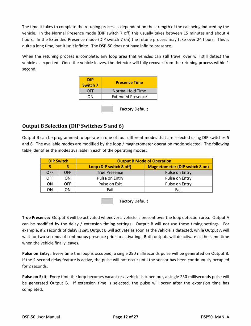
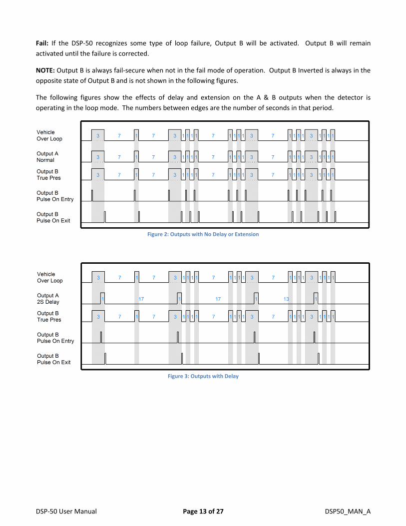
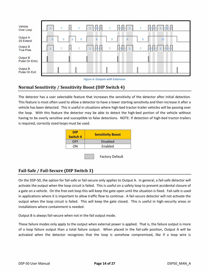
The following figures show the effects of delay and extension on the A & B outputs when the detector is
operating in the loop mode. The numbers between edges are the number of seconds in that period.
Figure 2: Outputs with No Delay or Extension
Figure 3: Outputs with Delay
DSP-50 User Manual Page 14 of 27 DSP50_MAN_A
Figure 4: Outputs with Extension
Normal Sensitivity / Sensitivity Boost (DIP Switch 4)
The detector has a user selectable feature that increases the sensitivity of the detector after initial detection.
This feature is most often used to allow a detector to have a lower starting sensitivity and then increase it after a
vehicle has been detected. This is useful in situations where high-bed tractor-trailer vehicles will be passing over
the loop. With this feature the detector may be able to detect the high-bed portion of the vehicle without
having to be overly sensitive and susceptible to false detections. NOTE: If detection of high-bed tractor-trailers
is required, correctly sized loops must be used.
DIP Switch 4
Sensitivity Boost
OFF Disabled
ON Enabled
Factory Default
Fail-Safe / Fail-Secure (DIP Switch 3)
On the DSP-50, the option for fail-safe or fail-secure only applies to Output A. In general, a fail-safe detector will
activate the output when the loop circuit is failed. This is useful on a safety loop to prevent accidental closure of
a gate on a vehicle. On the free exit loop this will keep the gate open until the situation is fixed. Fail-safe is used
in applications where it is important to allow traffic flow to continue. A fail-secure detector will not activate the
output when the loop circuit is failed. This will keep the gate closed. This is useful in high-security areas or
installations where containment is needed.
Output B is always fail-secure when not in the fail output mode.
These failure modes only apply to the output when external power is applied. That is, the failure output is more
of a loop failure output than a total failure output. When placed in the fail-safe position, Output A will be
activated when the detector recognizes that the loop is somehow compromised, like if a loop wire is

DSP-50 User Manual Page 15 of 27 DSP50_MAN_A
disconnected from its terminal screw. If placed in the fail-secure position, Output A does not activate when a
fault condition is identified.
DIP Switch 3
Failure Mode for Output A
OFF Fail-Safe
ON Fail-Secure
Factory Default
When a fault is identified the green Power LED will flash to indicate the type of fault that was found. See
Indicators – Power LED for more information on this display.
Delay / Extension (DIP Switches 1 and 2)
Delay is the time added after a vehicle arrives in the detection area before Output A is activated. During the
delay interval Output A will remain de-activated, requiring that the vehicle stay in the detection area for a full 2
seconds before activating Output A. This is useful at sites where vehicles traveling perpendicular to the gate
may travel across the detection zone. This interval is indicated by the red Detect A LED blinking slowly at 200
milliseconds on followed by 200 milliseconds off repeatedly until the interval is complete. The only delay setting
available is 2 seconds.
Extension is the time added after a vehicle leaves the detection area. During this interval, Output A will remain
activated, with the intent of allowing the vehicle to fully exit the detection area before the gate begins to close.
If another vehicle arrives during this extension interval, the remainder of the extension time is canceled and the
detector returns to the normal presence state. This interval is indicated by the red Detect A LED blinking fast at
50 milliseconds on followed by 50 milliseconds off repeated until the interval is complete. There are two
extension intervals to choose from, 2 seconds and 5 seconds.
When the detector is operating in the magnetometer mode the extension setting can be used to lengthen the
output pulse on Output B. If no extension is selected the output pulse will be 250 milliseconds long. Otherwise,
the output pulse length is equal to the extension time setting.
Delay and extension cannot be selected at the same time. The possible delay and extension settings are
summarized in the table below:
DIP Switch Output A Delay Time
Output A Extension Time 1 2
OFF OFF None None
OFF ON 2 seconds None
ON OFF None 2 seconds
ON ON None 5 seconds
Factory Default
DSP-50 User Manual Page 16 of 27 DSP50_MAN_A
Indicators
The DSP-50 is equipped with three (3) LED indicators: Power (Green), Detect A (Red), and Detect B (Red).
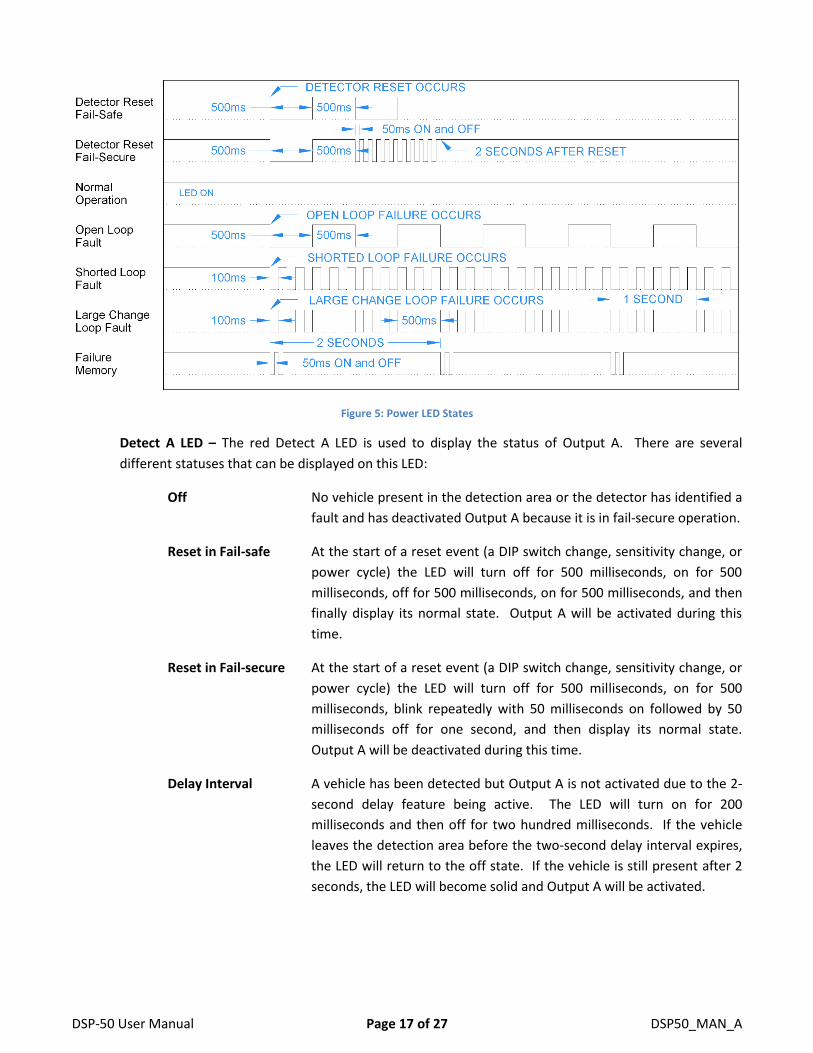
Power LED – The green power LED indicates these possible states:
Off The voltage applied to the detector is less than the minimum display
voltage of approximately 5 volts. The LED will be off.
Reset in Fail-safe At the start of a reset event (a DIP switch change, sensitivity change, or
power cycle) the LED will turn off for 500 milliseconds, on for 500
milliseconds, off for 500 milliseconds, off for 500 milliseconds, and then
display its normal state.
Reset in Fail-secure At the start of a reset event (a DIP switch change, sensitivity change, or
power cycle) the LED will turn off for 500 milliseconds, on for 500
milliseconds, blink repeatedly with 50 milliseconds on followed by 50
milliseconds off for one second, and then display its normal state.
Open Loop When the detector senses that the loop is open or the inductance is too
high, the LED will turn on for 500 milliseconds then off for 500
milliseconds repeatedly, for the duration of the fault. If the fault is
corrected the LED will display the Prior Fault indication.
Shorted Loop When the detector senses that a loop is shorted or the inductance is too
low; the LED will turn on for 100 milliseconds then off for 100
milliseconds repeatedly, for the duration of the fault. If the fault is
corrected the LED will display the Prior Fault indication.
Large Change Fault When the detector senses that a loop is experiencing a large inductance
change (greater than 30%), the LED will turn off for 100 milliseconds
then on for 100 milliseconds for 500 milliseconds then stay on for 500
milliseconds and repeat the sequence for the duration of the fault.
If the fault is corrected and the Fail Memory feature is enabled, the LED
will display the Prior Fault indication.
Prior Fault The detector is equipped with the ability to remember prior faults that
have occurred since the last power interruption or reset (changing a DIP
switch or the sensitivity). The LED will turn on for 1850 milliseconds, off
for 50 milliseconds, on for 50 milliseconds, off for 50 milliseconds and
then repeat the sequence until power is cycled or the detector reset.
Normal The LED is always on when the detector is in its normal state of
operation.
DSP-50 User Manual Page 17 of 27 DSP50_MAN_A
Figure 5: Power LED States
Detect A LED – The red Detect A LED is used to display the status of Output A. There are several
different statuses that can be displayed on this LED:
Off No vehicle present in the detection area or the detector has identified a
fault and has deactivated Output A because it is in fail-secure operation.
Reset in Fail-safe At the start of a reset event (a DIP switch change, sensitivity change, or
power cycle) the LED will turn off for 500 milliseconds, on for 500
milliseconds, off for 500 milliseconds, on for 500 milliseconds, and then
finally display its normal state. Output A will be activated during this
time.
Reset in Fail-secure At the start of a reset event (a DIP switch change, sensitivity change, or
power cycle) the LED will turn off for 500 milliseconds, on for 500
milliseconds, blink repeatedly with 50 milliseconds on followed by 50
milliseconds off for one second, and then display its normal state.
Output A will be deactivated during this time.
Delay Interval A vehicle has been detected but Output A is not activated due to the 2-
second delay feature being active. The LED will turn on for 200
milliseconds and then off for two hundred milliseconds. If the vehicle
leaves the detection area before the two-second delay interval expires,
the LED will return to the off state. If the vehicle is still present after 2
seconds, the LED will become solid and Output A will be activated.
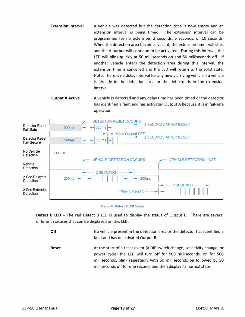
DSP-50 User Manual Page 18 of 27 DSP50_MAN_A
Extension Interval A vehicle was detected but the detection zone is now empty and an
extension interval is being timed. The extension interval can be
programmed for no extension, 2 seconds, 5 seconds, or 10 seconds.
When the detection area becomes vacant, the extension timer will start
and the A output will continue to be activated. During this interval, the
LED will blink quickly at 50 milliseconds on and 50 milliseconds off. If
another vehicle enters the detection area during this interval, the
extension time is cancelled and the LED will return to the solid state.
Note: There is no delay interval for any newly arriving vehicle if a vehicle
is already in the detection area or the detector is in the extension
interval.
Output A Active A vehicle is detected and any delay time has been timed or the detector
has identified a fault and has activated Output A because it is in fail-safe
operation.
Figure 6: Detect A LED States
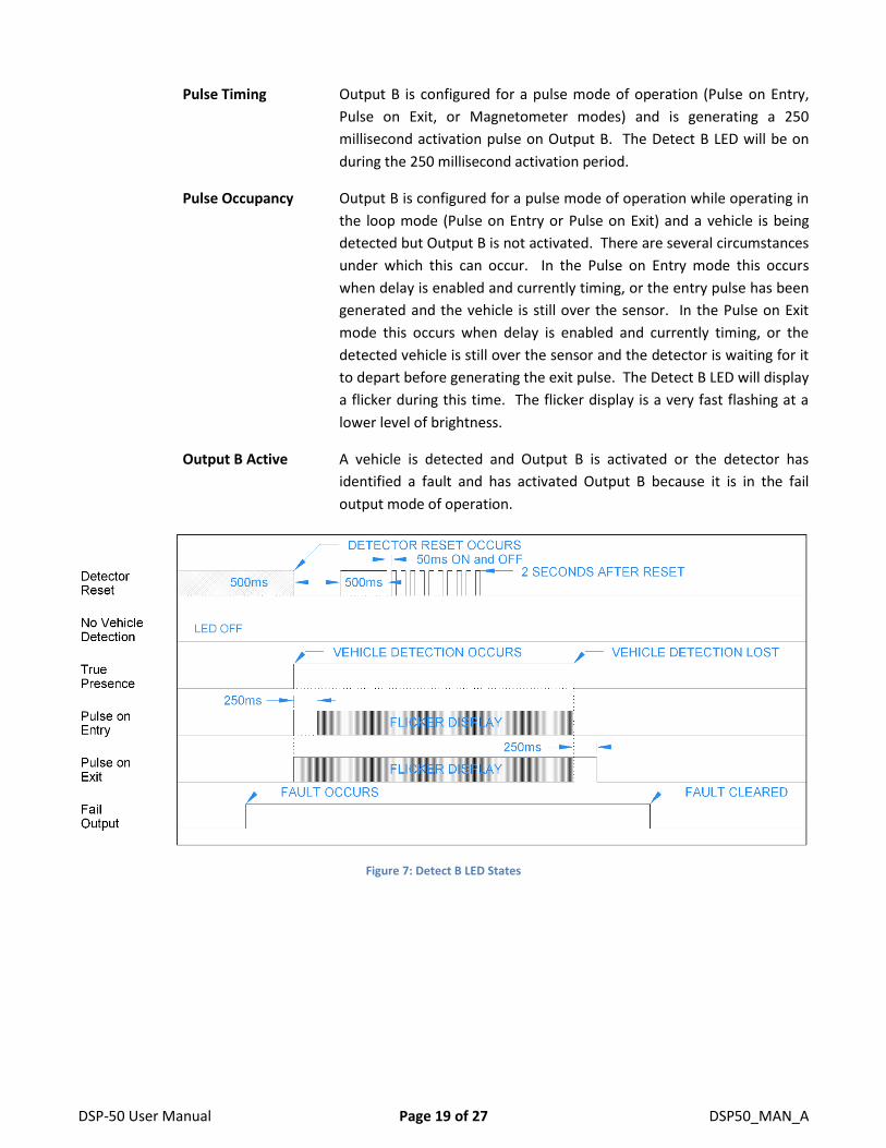
Detect B LED – The red Detect B LED is used to display the status of Output B. There are several
different statuses that can be displayed on this LED:
Off No vehicle present in the detection area or the detector has identified a
fault and has deactivated Output B.
Reset At the start of a reset event (a DIP switch change, sensitivity change, or
power cycle) the LED will turn off for 500 milliseconds, on for 500
milliseconds, blink repeatedly with 50 milliseconds on followed by 50
milliseconds off for one second, and then display its normal state.
DSP-50 User Manual Page 19 of 27 DSP50_MAN_A
Pulse Timing Output B is configured for a pulse mode of operation (Pulse on Entry,
Pulse on Exit, or Magnetometer modes) and is generating a 250
millisecond activation pulse on Output B. The Detect B LED will be on
during the 250 millisecond activation period.
Pulse Occupancy Output B is configured for a pulse mode of operation while operating in
the loop mode (Pulse on Entry or Pulse on Exit) and a vehicle is being
detected but Output B is not activated. There are several circumstances
under which this can occur. In the Pulse on Entry mode this occurs
when delay is enabled and currently timing, or the entry pulse has been
generated and the vehicle is still over the sensor. In the Pulse on Exit
mode this occurs when delay is enabled and currently timing, or the
detected vehicle is still over the sensor and the detector is waiting for it
to depart before generating the exit pulse. The Detect B LED will display
a flicker during this time. The flicker display is a very fast flashing at a
lower level of brightness.
Output B Active A vehicle is detected and Output B is activated or the detector has
identified a fault and has activated Output B because it is in the fail
output mode of operation.
Figure 7: Detect B LED States
DSP-50 User Manual Page 20 of 27 DSP50_MAN_A
5. Installation
Detector Installation
Location: The detector should be installed in a weatherproof location that is near the loop. Ideally, a technician
should be able to see the loop and the detector at the same time.
Mounting: The detector will function when mounted in any orientation. If the operator does not have a
connector for the detector to directly plug in to, an adapter board will be needed (RK-1 or RK-3). Mount the
adapter board such that the switches and LEDs on the detector will be easily accessible for configuration and
troubleshooting.
Wiring: If plugging the detector in to the operator, you should be certain that the operator pin out for its
connector is the same as that of the DSP-50 detector and that the voltage supplied to the detector is between
10 and 30 volts DC.
If using an adapter board, terminate all wires on to the adapter board before plugging to detector into the
board. Wire nuts should never be used at any point in the loop circuit itself. All loop connections should be
crimped or screw terminals at a minimum and soldered for best long-term reliability.
Special attention should be paid to ensure that the loop wires remain tightly twisted together. An air gap
between the two wires for a loop may cause the detector to lock up if the wires are disturbed.
Remember that the DSP-50 uses solid-state outputs and can only sink current. Therefore, if you want to drive a
relay coil with an output, the other side of the relay coil must be connected to an appropriate voltage (for the
coil) positive DC supply. Using an AC relay is not possible and may damage the detector. The detector has
snubber diodes built in for all of the solid-state (open-collector) outputs in case they do drive a relay coil.
Loop Installation
The reliability and overall performance of the detector are greatly dependent on the loop itself. Several factors
go into a good loop installation: type of wire used, loop configuration, and installation practices.
Type of Wire Used: The wire used for wiring the loop should have a jacket of cross-linked polyethylene or
similar material that has very low moisture absorption properties. This would be a wire with an XLP jacket such
as XHHW. THHN or similar wire types should never be used for loop wire.
The gauge of the wire to use depends on two factors: Distance in cable feet from the loop to the detector and
stresses the wire may see. The gauge of the wire can be 20 AWG as long as the detector is within 50 feet of the
loop in cable distance. For 50 to 100 feet, use at least 18 AWG wire. At greater than 100 feet, use a 16 AWG
wire at a minimum. If the loop is installed in asphalt and there will be heavy vehicles or stopping and starting
vehicles in the loop area, a 14 AWG or 12 AWG should be used to provide additional strength to the loop. This
helps increase the life of the loop in areas where the asphalt may slowly move and/or deform due to wear.
DSP-50 User Manual Page 21 of 27 DSP50_MAN_A
Loop Configuration: The size and shape of the loop will determine what type of vehicles it can reliably detect.
There are many variables that come into play including loop dimensions, percent of coverage, length of lead-in
wire, number of turns in the loop area, and detection height to name just a few of them. One common rule is
that the useable field height of a loop is 2/3 of the shortest leg of the loop. So if you plan on using a 2.5’ x 6’
loop, the expected useable detection height would be 20” (The shortest leg is 2.5’ or 30”, 30” x 2 = 60”, 60” / 3 =
20”). If the installation requires the detection of motorcycles as well as vehicles, the loop should go to within
one foot of the curb or roadway edge, whichever is present. If only motor vehicle detection is required, within
three feet of the curb or roadway edge is all that is required.
The number of turns to use in a loop is dependent on the size of the loop, the amount of metal (rebar, cables,
etc.), and distance from the loop to the detector. Rather than dive into all of the calculations to arrive at a
value, we will just use safe values. You can almost never have too many turns in a loop, only too few. For a loop
size of 2’ x 6’, four turns will be sufficient unless there is metal in the loop area. In that case add at least one
turn, and two if possible. As the loop size reaches 6’ x 6’, four turns will work for most all installations. If you
are unsure about your particular installation, call tech support for guidance.
Installation Practices: Permanent loops should be installed into the road surface by cutting slots into the road
surface using a saw with an appropriate cutting disk for the road surface.
The slot cut should be wide enough that the wire being used will easily fit into the slot. This is needed so that
the loop sealant used can fully encapsulate the wire. When the wire fits tightly in the slot, the sealant may not
be able to get below the wire, leaving air pockets in the saw slot. If water finds its way in to these air pockets,
over time, freeze thaw cycles can slowly jack the loop out of the saw slot causing loop failure.
The saw slot should be deep enough that the loop wire will have a minimum of ½” of sealant over the top wire
in the slot. More is better. Going too deep with the saw cut is also a concern. Deep cuts in a road surface may
impact the structural strength of the roadway, especially if any reinforcement material is cut. Using a smaller
gauge of wire will allow for shallower saw cuts.
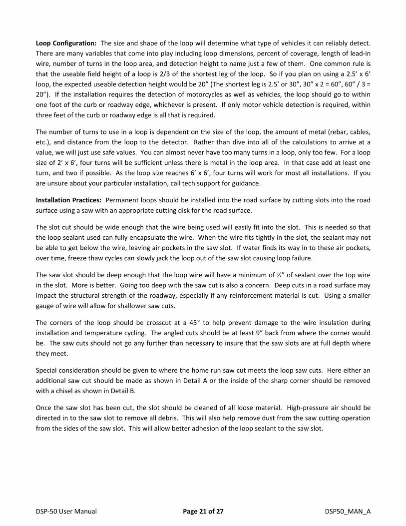
The corners of the loop should be crosscut at a 45° to help prevent damage to the wire insulation during
installation and temperature cycling. The angled cuts should be at least 9” back from where the corner would
be. The saw cuts should not go any further than necessary to insure that the saw slots are at full depth where
they meet.
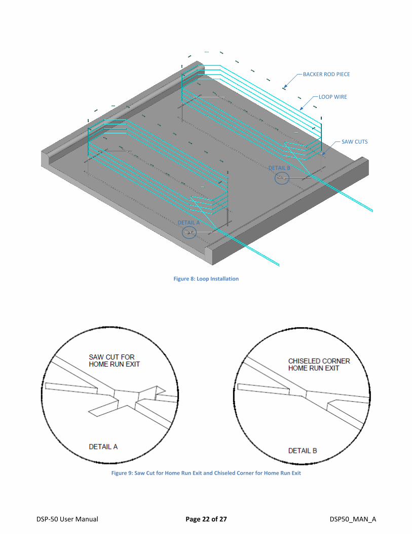
Special consideration should be given to where the home run saw cut meets the loop saw cuts. Here either an
additional saw cut should be made as shown in Detail A or the inside of the sharp corner should be removed
with a chisel as shown in Detail B.
Once the saw slot has been cut, the slot should be cleaned of all loose material. High-pressure air should be
directed in to the saw slot to remove all debris. This will also help remove dust from the saw cutting operation
from the sides of the saw slot. This will allow better adhesion of the loop sealant to the saw slot.
DSP-50 User Manual Page 22 of 27 DSP50_MAN_A
Figure 8: Loop Installation
Figure 9: Saw Cut for Home Run Exit and Chiseled Corner for Home Run Exit
BACKER ROD PIECE
LOOP WIRE
SAW CUTS
DETAIL A
DETAIL B
DSP-50 User Manual Page 23 of 27 DSP50_MAN_A
The loop wire should be installed as a continuous piece of wire from the detector to the loop, all of the turns in
the loop, and back to the detector. Remember to make allowance for shrinkage in the wire length when the
portion of the wire not in the roadway surface is twisted. The twisting is important for dealing with electrical
noise. A splice of the loop wire should never be made in the roadway. If the loop wire needs to be spliced to
another cable to get to the detector, the splice should be done in a junction box and the connections should be
soldered and weatherproofed. Wire nuts should never be used at any point in the loop circuit.
In order to keep the loop wire at the bottom of the saw slot, 1” to 2” pieces of backer rod should be placed in
the saw slot every 1 to 2 feet. The backer rod should be sized such that it fits snugly in the saw slot. Use a blunt
object (not a screwdriver) to press the backer rod pieces down into the saw slot as far as they will go. Keeping
the loop wire at the bottom of the saw slot allows the loop sealant to provide the maximum amount of
protection possible from foreign object penetration. Never use a continuous piece of backer rod over the loop,
as this would prevent the loop sealant from encapsulating the loop wire.
The loop sealant used should be appropriate for the roadway surface that was cut. Generally, epoxy or
polyester based sealants are used for concrete surfaces and polyester or urethane based sealants are used for
asphalt surfaces. However these are not hard guidelines and specific circumstances will determine which type
of sealant should be used.
Once the loop wire leaves the saw slot it should be twisted at least three times per foot. More is better. The
twists should be kept tight to be most effective in reducing the effects of electrical interference.
6. Configuration
Wiring
There is only one wiring configuration (pin-out) offered for the DSP-50.
Pin Function
1 Loop or Mini-Loop
2 Loop or Mini-Loop
3 DC +
4 Not Connected
5 Not Connected
6 Output B
7 Output B Inverted
8 Output A
9 DC +
10 DC Common
DSP-50 User Manual Page 24 of 27 DSP50_MAN_A
7. Troubleshooting
No Power LED
The first step is to ensure that the correct model of the detector is being used for the installation. Ensure that
the wiring is correct and the correct voltage is being used.
Use a meter to measure the voltage applied to the detector. The voltage must be between 10 volts and 30 volts
AC or DC.
If the correct voltage is applied and the power LED is not on, replace the detector.
Power LED Flashes Slowly (1 Hz)
This flash rate indicates that the detector has an open loop, a high resistance in the loop circuit, or excessive
inductance.
The first step is to confirm that the detector has a loop connected to it and the loop is connected to the correct
pins (see the wiring configuration for the pin out).
If a loop is connected to the correct pins of the detector, disconnect the loop and using an ohmmeter, check the
resistance of the loop circuit. If the resistance is above 5 ohms there is a bad connection or the wire has been
damaged. The resistance will typically be 1.5 ohms or less.
If the resistance is below 5 ohms, the loop inductance should be checked. This is done using an inductance
meter. The inductance of the loop should be less than 1500 microhenries. It is very unusual to have a loop with
an inductance value this high, but it is possible with very large loops and many turns. If the loop inductance
value is above 1500 microhenries, the loop will have to be replaced with a loop with less inductance. Contact
technical support for help with very large loops.
If you do not have a meter capable of measuring resistance and inductance but do have another operating
detector in the same box, you can skip to this step. Swap the loops between a working detector and a failing
detector. If the problem follows the loop the loop is the problem. If it stays in the same detector, replace the
detector.
Power LED Flashes Quickly (5 Hz)
This flash rate indicates that the channel has a shorted loop, a low resistance across the loop circuit, or
insufficient inductance.
The first step is to confirm that the loop is connected to the correct pins (see the wiring configuration for the pin
out). If the wiring is correct, the next step is to confirm that the detector is working correctly. Disconnect the
loop wires for the detector. The LED should begin flashing at a much slower rate (½ second on, ½ second off). If
it does not change its flashing rate, change the detector.
DSP-50 User Manual Page 25 of 27 DSP50_MAN_A
If a loop is connected to the correct pins of the detector, disconnect the loop and using an ohmmeter, check the
resistance of the loop circuit. If the resistance is below 0.2 ohms there is a short in the loop circuit. The
resistance will typically be 0.5 ohms to 1.5 ohms.
If the resistance is above 0.2 ohms, the loop inductance should be checked. This is done using an inductance
meter. The inductance of the loop should be more than 20 microhenries. If the loop inductance is less than 20
microhenries, the loop was probably not wound correctly and only has one turn in it. In this case the loop must
be replaced. Other possibilities include a foreign object embedded in the saw clot and shorting some or all of
the wires, or failed wire insulation due to the wire being exposed or the wrong type of wire being used. Very
small loops may also have a low inductance value if sufficient turns were not added. Contact technical support
for help with very small loops.
If you do not have a meter capable of measuring resistance and inductance but do have another operating
detector in the same box, you can skip to this step. Swap the loops between a working detector and a failing
detector. If the problem follows the loop the loop is the problem. If it stays in the same detector, replace the
detector.
Power LED Shows Two Quick Flashes Once Every Two Seconds
This flash rate indicates that the channel has had a failure of some type, but is currently working correctly.
Intermittent failures are usually open loop failures. Any splices in the loop wire should be redone. If there are
any wire nuts used in the loop circuit, remove them, and replace with a crimp connection or preferably, a
soldered connection. The open loop fault could also be a fatigued point in the loop wire. This can occur at
locations where the loop wires cross an expansion joint in the road surface. Any place where the loop wires
must move, even if only a very tiny amount, can cause wire fatigue. The actual failure point may be very difficult
to find. Often the loop must just be replaced if the issue persists but cannot be found.
It is possible for the intermittent failure to be a shorted loop fault. One possible source of this type of fault is a
foreign object being embedded in the loop saw cut and damaging the wire. Another is that the loop wire has
been damaged where it enters or exits a conduit or junction box, or that a conduit that the loop wire is in has
been damaged (crushed, kinked, bent, cut, etc.).
Detect LED Intermittently Comes On / Stays On Without a Vehicle Present
This type of symptom is usually caused by one of three issues: physical issues with the loop, electrical
interference, moving objects in proximity to the loop.
Physical Issues with the Loop – There are many ways in which a loop installation can go bad. The insulation of
the loop wire can fail. This can be due to the loop wire being exposed in the saw lot, damage to the wire
insulation during loop installation, physical stressing of the wire due to movement (crossing of expansion joints
or asphalt that has slowly moved or deformed), wires moving in the saw slot due to poor loop sealant
encapsulation, foreign objects embedded in the saw slot, and poor electrical connections in the loop circuit.
DSP-50 User Manual Page 26 of 27 DSP50_MAN_A
The best way to check for any of these issues is to use a megohmmeter (commonly referred to as a megger).
Disconnect the loop wires in question from the vehicle detector and any other electronic equipment. Connect
one lead of the megger to one end of the loop wire and the other lead to earth ground. Measure the resistance.
For accurate measurements the ground and the loop should be wet or at least damp (use a hose or a bucket of
water if needed to get the area wet). The reading should be at least 100 megohms. If it is less than 50
megohms the insulation is compromised and the loop circuit has to be replaced. Between 50 and 100
megohms, the loop may or may not work properly and reliably.
Electrical Interference – There are several possible sources of electrical interference: loop cross-talk, power
lines, electric motors, and insufficient twisting of the loop wires, just to name a few.
Other loops in the area that are connected to a different detector are prone to cross-talk (when the magnetic
fields from different loops interfere with each other). Adjusting the loop frequency of one or both of the loops
in the same area will usually allow you to find a setting that both loops will work reliably with.
Anything that uses electricity is a possible source for electrical interference depending on its proximity to the
loop and the amount of energy being used. If you believe the loop is experiencing electrical interference, turn
off the device believed to be the source of the interference and see if the problem goes away. Sometimes this is
not possible and more technical means are needed to help identify the source. Call Technical Support in this
case.
If the electrical interference is occurring in the wire from the loop to the detector, additional twisting should
help mitigate the issue.
Moving Objects in Proximity to the Loop – Objects that can move and are metallic or somehow electrically
conductive, may cause detection issues.
A common issue is movement of a slide gate or gate arm in close proximity to a loop. The best solution would
be to move the detection area further away from the moving gate. We recommend that all loops should be at
least 4 feet from a slide gate. Try lowering the sensitivity one level so that the desired vehicles are still detected,
but not the moving gate. NOTE: Do not lower the sensitivity too much or vehicles will no longer be detected.
Another possibility is metal objects in close proximity to the loop. Utility manhole covers are objects that may
move slightly when vehicle tires drive over them, especially if the vehicle turns while a tire in on the cover. Most
manhole covers can be bolted in place. Contact the owner of the manhole to see what can be done to mitigate
the cover movement.
Detect LED Will Not Come On With a Vehicle Present
The first thing to do is verify that the LED in question is still working. This is accomplished by a quick lamp test.
Reset the detector by temporarily changing DIP switch 1. Both LEDs should turn off and turn on. If the Detect
LED does not illuminate, replace the detector.
If the red LED illuminates, then perhaps the sensitivity setting is too low. There are many variables in
determining overall sensitivity: loop size, number of turns, loop lead-in, percent coverage, etc. In most cases, a
sensitivity setting of 5 is the correct setting. However, to compensate for some unusual loop geometries, this

DSP-50 User Manual Page 27 of 27 DSP50_MAN_A
setting may be inadequate. Adjust the sensitivity one level higher and recheck the detector for proper
detection.
If the channel sensitivity is set to 9 and the red LED still does not come on and you have another operating
detector in the same box, swap the loops between a working detector and a failing detector. If the problem
follows the loop the loop is the problem. If it stays in the same detector, replace the detector.