Embed Size (px)
DESCRIPTION
Dslam configuration guide and how to install and use this devices
Citation preview
‐ 1 ‐
DSLAM Configuration Guide
A Guide for configuring DSLAM5008/5012/5016/5024
‐ 2 ‐
Contents 1 About this Guide ......................................................................................................................................7
1.1 Structure of this guide ...................................................................................................................7
1.2 Purpose and Audience ...................................................................................................................7
1.3 Organization...................................................................................................................................7
2 System Overview...........................................................................................................................................8
2.1 System feature...............................................................................................................................8
2.1.1 ATM feature.........................................................................................................................8
2.1.2 DSL feature .........................................................................................................................8
2.1.3 Routing and IP features ........................................................................................................8
2.1.4 Bridging features ..................................................................................................................8
2.1.5 Management features..........................................................................................................9
2.2 CLI overview...................................................................................................................................9
2.2.1 CLI features...........................................................................................................................9
2.2.1 CLI help .................................................................................................................................9
2.2.2 CLI Edit ................................................................................................................................10
2.2.3 Configure DSLAM using CLI ................................................................................................11
2.3 Basic Network For Configuration.................................................................................................13
3 Configuring the IP Stack ..........................................................................................................................15
3.1 Supported protocols and features...............................................................................................15
3.1.1 Creating IP interfaces..........................................................................................................15
3.1.2 Displaying information about interfaces ............................................................................16
3.1.3 Creating virtual interfaces ..................................................................................................16
3.1.4 Deleting IP interfaces..........................................................................................................17
3.1.5 Setting IP interface addresses ............................................................................................17

‐ 3 ‐
3.1.6 Attaching the bridge ...........................................................................................................17
3.1.7 Configuring routes ..............................................................................................................18
4 Configuring the Bridge ...........................................................................................................................21
4.1 Introduction .................................................................................................................................21
4.2 Overview of Q‐bridge support .....................................................................................................22
4.2.1 Frame header tags ..............................................................................................................22
4.2.2 802.1P support ...................................................................................................................22
4.2.3 VLAN Learning Mechanisms ...............................................................................................23
4.3 Basic bridge configuration ...........................................................................................................23
4.4 Q‐bridge CLI commands...............................................................................................................26
4.4.1 Creating VLANs ...................................................................................................................26
4.4.2 Creating VLAN ports............................................................................................................27
4.4.3 Ingress filtering vlan‐tagged frames....................................................................................28
4.4.4 Accepting/rejecting incoming frames.................................................................................28
4.4.5 Forwarding and filtering frames .........................................................................................29
4.4.5 Prioritizing frames...............................................................................................................30
4.4.6 Bridge VLAN transport ........................................................................................................31
4.5 Example Q‐bridge configurations ................................................................................................32
4.5.1 LAN isolation using VLANs......................................................................................................32
4.5.2 VLANs Spanning Multiple Switches.....................................................................................35
4.5.3 Traffic prioritization ............................................................................................................37
4.6 IGMP Snoop Support ...................................................................................................................40
4.6.2 Benefits of IGMP Snoop in D‐bridge mode .........................................................................41
4.6.3 Benefits of IGMP Snoop in Q‐bridge mode.........................................................................41
4.6.4 Example IGMP Snoop Configuration...................................................................................42
5 Configuring ports....................................................................................................................................44

‐ 4 ‐
5.1 Configuring ports using the CLI ....................................................................................................44
5.1.1 Displaying available ports ...................................................................................................44
5.1.2 Displaying specific port information...................................................................................45
5.1.3 Configuring a specific port ..................................................................................................47
6 Configuring DSL.......................................................................................................................................48
6.1 Introduction .................................................................................................................................48
6.2 Displaying DSL port attributes .....................................................................................................48
6.3 Configuring DSL port attributes ...................................................................................................51
6.4 Configuring the DSL standard ......................................................................................................52
6.5 Configuring the DSL annex type...................................................................................................53
7 Configuring System logging....................................................................................................................54
7.1 Displaying system information ....................................................................................................54
7.2 Clearing, saving and restoring configurations .............................................................................54
7.2.1 Clearing the current configuration .....................................................................................54
7.2.2 Saving configuration changes .............................................................................................55
7.2.3 Restoring a configuration ...................................................................................................55
7.3 Updating system firmware...........................................................................................................55
8 Configuring RFC1483 ..............................................................................................................................56
8.1 Ethernet ‐ RFC1483 bridged.........................................................................................................56
8.1.1 Configure PC A and PC B .....................................................................................................57
8.1.2 Configure the DSLAM .........................................................................................................57
9 Configuring User Accounts...........................................................................................................................59
9.1 Administering user accounts .......................................................................................................59
9.1.1 Adding new user accounts ..................................................................................................59
9.1.2 Configuring existing user accounts .....................................................................................60
9.1.3 Configuring user logins and passwords...............................................................................61

‐ 5 ‐
10 Configuring Snmp agent.............................................................................................................................62
10.1 Snmp agent config.........................................................................................................................62
10.1.1 Display snmp config .............................................................................................................62
10.1.2 Configure snmp....................................................................................................................62
10.2 Snmp communitynames ...............................................................................................................62
10.2.1 Display snmp commnuitynames .........................................................................................62
10.2.2 Create snmp commnuitynames ..........................................................................................63
11 Configuring with EmWeb ....................................................................................................................64
11.1 References to CLI commands...................................................................................................64
11.2 Accessing EmWeb ....................................................................................................................64
11.2.1 Logging in to EmWeb..........................................................................................................65
11.2.2 About the Engineer web page menus.................................................................................65
11.3 Save configuration ...................................................................................................................66
11.4 Authentication .........................................................................................................................66
11.3.1 Creating a new login account ..............................................................................................67
11.4.2 Editing/deleting a login account .........................................................................................67
11.5 LAN connections ......................................................................................................................68
11.5.1 Creating new LAN connections...........................................................................................68
11.5.3 Configuring primary and secondary LAN connections........................................................69
11.5.4 Creating virtual interfaces ..................................................................................................70
11.6 WAN connections.....................................................................................................................70
11.6.1 Creating a WAN service ......................................................................................................71
11.6.2 Editing a WAN service.........................................................................................................72
11.6.3 Deleting a WAN service.......................................................................................................72
11.6.4 Creating a virtual interface (routed services only)..............................................................72
11.6.5 Creating an IP V4 Route .....................................................................................................72

‐ 6 ‐
11.6.6 Editing a route....................................................................................................................73
11.6.7 Deleting a route .................................................................................................................74
11.7 Bridge ............................................................................................................................................74
11.7.1 Interface configuration ......................................................................................................75
11.7.2 VLAN Configuration ...........................................................................................................75
11.7.3 Source MAC Based Unicast Filtering Entry Configuration ..................................................76
11.7.4 Destination MAC Based Unicast Filtering Entry Configuration ..........................................76
11.7.5 Multicast Filtering Entry Configuration..............................................................................77
11.7.6 Forward All and Forward Unregistered Entry Configuration .............................................78
11.7.8 VLAN port statistics............................................................................................................79
11.8 Ports...............................................................................................................................................80
11.8.1 Configuring ports ...............................................................................................................80
Chapter 1 About this Guide
‐ 7 ‐
1 About this Guide 1.1 Structure of this guide
This guide describes how to use Command-Line Interface(CLI) to configure your DSLAM, including model 5008, 5012, 5016 and 5024.
Do not proceed until you have completed all the hardware connections. 1.2 Purpose and Audience
The intention of this DSLAM configuration guide is the following:
• To help the application engineer to evaluate the software features of the DSLAM. • To use the Command-Line Interface(CLI) for application engineer to create a customized default
configuration for his own product design.
• To let the ISP to modify the unit configuration in the field.
1.3 Organization
The remainder of this DSLAM Configuration Guide is organized as follows:
Chapter 2 System overview describes the DSLAM software feature. Chapter 3 Basic Configuration describes the basic network setup and the methods to configure it. Chapter 4 Configuring the IP Stack describes how to setup your router by configuring the IP stack. Chapter 5 Configuring the Bridge describes how to configure the 802.1D and 802.1Q Bridge. Chapter 6 Configuring ports describes the ports available on your device. Chapter 7 Configuring DSL describes how to change your DSL configuration. Chapter 8 Configuring System logging describes how to configure system logging on. Chapter 9 Configuring RFC1483 describes how to configure RFC 1483 bridged and routed
networks. Chapter 10 Configuring User Accounts describes how to administer the user accounts on your
network. Chapter 11 Configuring SNMP agent describes how to configure SNMP agent.

Chapter 2 Basic Configuration
‐ 8 ‐
2 System Overview
Features of the ISOS software is summarized as follow:
2.1 System feature
2.1.1 ATM feature
Provides ATM layer functionality (per I.361) Provides adaptation layer (AAL5, AAL0) functionality(per I.363.5) Supports UBR, CBR rt-VBR & nrt-VBR service classes in accordance with ATM forum TM 3.1.
DSL-aware CAC Supports IP over ATM (IPoA, RFC 1483 & RFC 1577) Supports Ethernet over ATM (EoA, RFC 2684 - superseding RFC 1483)
2.1.2 DSL feature
Supports fast and interleaved latency Supports the following types of line coding:- DMT: T1.413, G.992.1, G.992.2 with auto-detection,
G.992.3 (G.dmt.bis / ADSL2) andG.992.5 (ADSL2plus) ADSL downstream data rates up to 12 Mbps,DSL2plus data rates up to 24 Mbps
2.1.3 Routing and IP features
The software supports the following protocols: IP layer stack supported. User Datagram Protocol (UDPv4) Transmission Control Protocol Address Resolution Protocol (ARP) Internet Control Message Protocol Routing Information Protocol (RIP) v1 and v2 IP Fragmentation and Reassembly Virtual interfaces and secondary IP addresses IGMP, IGMP Proxy and Multicasting TCP Maximum Segment Size (MSS) Clamp changes the MSS in the TCP header of packets, so they
do not require fragmentation when sent over a link with a smaller MTU
2.1.4 Bridging features
Layer 2 MAC Transparent bridge as specified in IEEE802.1D and 802.1Q; VLAN and 802.1p priority support Bridged PDU encapsulation (per RFC 2684) Bridge Source MAC Address forwarding. Forwarding IPpackets based on MAC address of the packet Spanning Tree bridge IEEE 802.1D

Chapter 2 Basic Configuration
‐ 9 ‐
IGMP Snooping support - allows multicast packets to be forwarded intelligently to ensure more efficient use of network bandwidth
2.1.5 Management features Device/network management has following features:
EmWeb Web-based Graphical User Interface (GUI) enabling end-user device configuration via HTTP.
Support SNMP v1, v2 SNMP MIB II, DSL MIB, ATM MIB Command Line Interface (CLI) via serial interface or Telnet over Ethernet or DSL Update of boot image or configuration data over HTTP/ TFTP including HTTP One-Click firmware
upgrade.
2.2 CLI overview
2.2.1 CLI features
Support local configuration by Console(RS-232)port.
Support remote configuration by Telnet Provide a function similar to DosKey to display history commands. Enter “?” to get online help at any time Enter “tab” to match commands
2.2.1 CLI help
The Command Line interface provides online help to users: A user can simply type “?” at the Command Line prompt A list of all the commands and their descriptions will appear. For example
?
Below is the corresponding output: agent Get a file from a remote host bridge Configure layer 2 bridge. bridgevlan console Console access ethernet Commands to configure ethernet transports help Top level CLI help igmp imdebug Directly access the information model ip Configure IP router port Physical port configuration commands rfc1483 Commands to configure RFC1483 transports snmp source Read a file of commands
Chapter 2 Basic Configuration
‐ 10 ‐
system System administration commands transports Transport configuration commands user User commands webserver Webserver configuration commands Type in one command and “?” with space in between (command ?) It will list all keyword and description about this command For example(in this case, command is “ip”):
ip ?
Below is the corresponding output: --> ip add attach attachbridge attachvirtual clear delete detach interface list ping set show --> ip Type in one parameter and “?” with space in between (parameter ?) It will list all keyword and description about this parameter If there is no corresponding parameter, the CLI will return the same command line, hit “Enter” to exit. Type in one string and “?” with space in between (string ?) It will list all the commands beginning with the string. For example:
i?
Below is the corresponding output: --> b bridge bridgevlan --> b Type in the first few letters of the command and press <tab>. It will automatically display the complete command given this command name is unique.
2.2.2 CLI Edit
Command Line Interface provides basic command editor as:
key Attribute
Normal key Provide basic command input, and case insensitive
Chapter 2 Basic Configuration
‐ 11 ‐
Backspace Delete one character ahead
→ Move the cursor one character after
← Move the cursor one character ahead
↑
↓
Display history command
Del Delete the character on the cursor
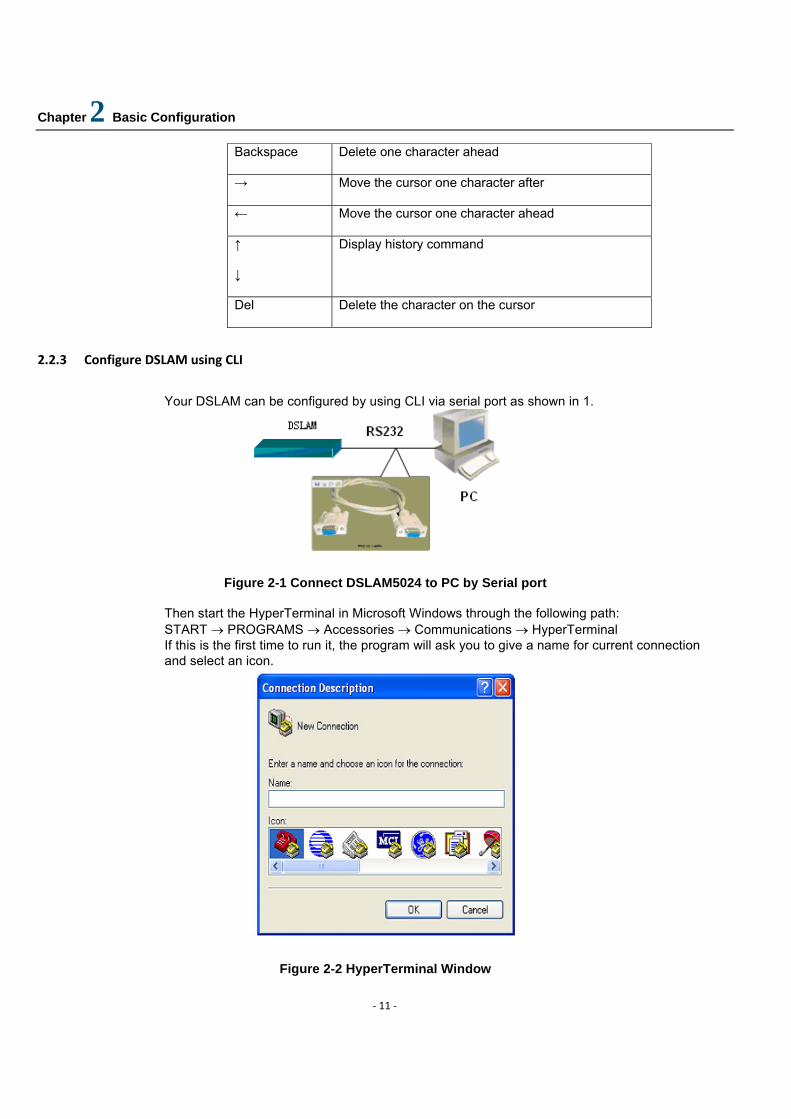
2.2.3 Configure DSLAM using CLI
Your DSLAM can be configured by using CLI via serial port as shown in 1.
Figure 2-1 Connect DSLAM5024 to PC by Serial port Then start the HyperTerminal in Microsoft Windows through the following path: START → PROGRAMS → Accessories → Communications → HyperTerminal If this is the first time to run it, the program will ask you to give a name for current connection and select an icon.
Figure 2-2 HyperTerminal Window
Chapter 2 Basic Configuration
‐ 12 ‐
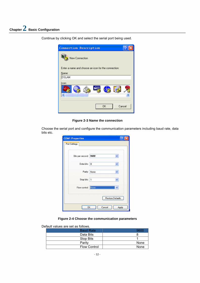
Continue by clicking OK and select the serial port being used.
Figure 2-3 Name the connection
Choose the serial port and configure the communication parameters including baud rate, data bits etc.
Figure 2-4 Choose the communication parameters Default values are set as follows.
Baud Rate 9600 Data Bits 8 Stop Bits 1 Parity None Flow Control None

Chapter 2 Basic Configuration
‐ 13 ‐
You can also configure DSLAM using CLI by telnet, see figure 2-5,the default IP address is :192.168.1.32.
Figure 2-5 Telnet DSLAM
2.3 Basic Network For Configuration
Following describes the basic ADSL network and how to configure it. The majority of configurations described throughout this guide assume that you have setup your device to act as a DSLAM. Consider the network below:
Figure 2-6: Basic Ethernet network
In this example, the hardware connections are as follows:

Chapter 2 Basic Configuration
‐ 14 ‐
• the device is configured via the HyperTerminal PC attached to the serial port. • the Internet is attached to the device’s 10BaseT/100BaseTX Ethernet port. • the PC A is attached to the device’s DSL port via ADSL modem.
Once you have booted the device, its configuration can be changed interactively:
• Using the Command Line Interface (CLI). The CLI is supported by the Versatile Management Interface (VMI) and is the priority configuration method described throughout this guide.
• Using the ISOS Embedded Webserver (EmWeb).
Chapter 3 Configuring the IP Stack
‐ 15 ‐
3 Configuring the IP Stack
This chapter provides an introduction on how to setup IP stack.
The IP stack contains a suite of networking routing protocols for use in embedded networking. It allows you to configure basic connectivity for your network to provide IP routing between interfaces and support local applications such as Telnet, Webserver and alike.
3.1 Supported protocols and features
3.1.1 Creating IP interfaces
You must attach one or more interfaces to the IP stack and attach a transport to it. For IP interfaces, each interface must be configured with an IP address and a subnet mask. Together, these define the range of addresses which can be reached via the interface without passing through any other routers.
Each interface must have a unique subnet; the range of addresses on each interface must not overlap with any other interface.
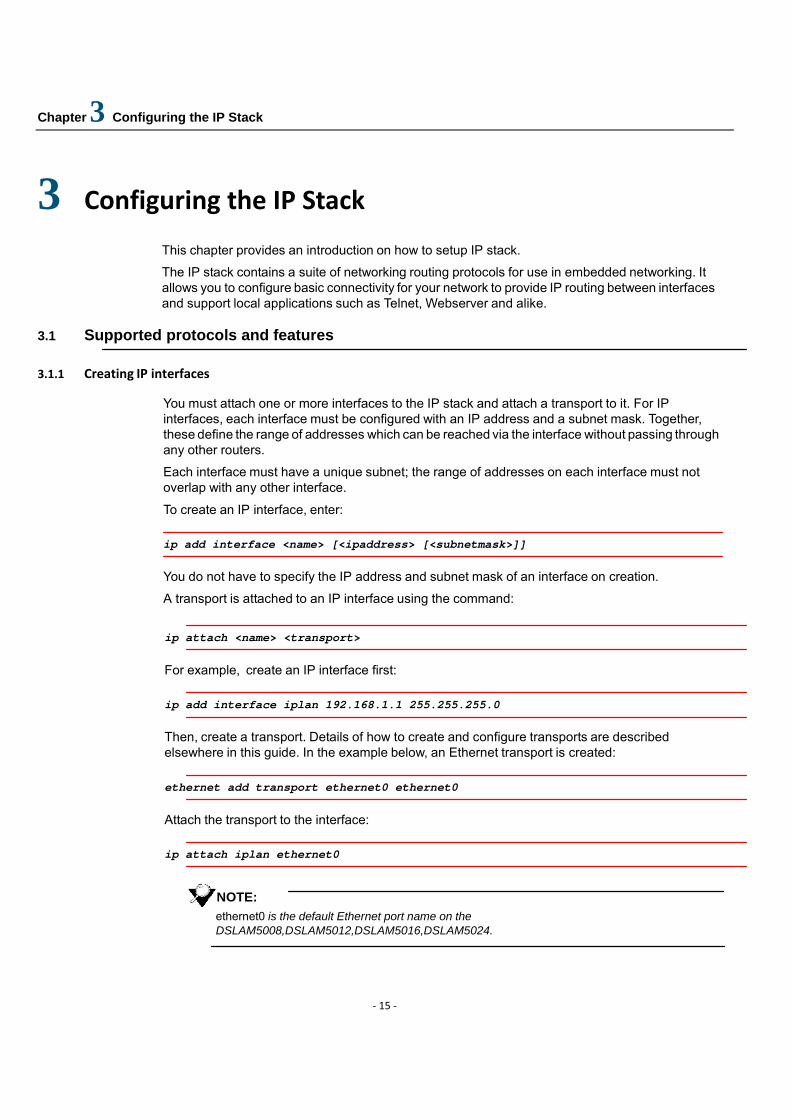
To create an IP interface, enter:
ip add interface <name> [<ipaddress> [<subnetmask>]]
You do not have to specify the IP address and subnet mask of an interface on creation.
A transport is attached to an IP interface using the command:
ip attach <name> <transport>
For example, create an IP interface first:
ip add interface iplan 192.168.1.1 255.255.255.0
Then, create a transport. Details of how to create and configure transports are described elsewhere in this guide. In the example below, an Ethernet transport is created:
ethernet add transport ethernet0 ethernet0
Attach the transport to the interface:
ip attach iplan ethernet0
NOTE: ethernet0 is the default Ethernet port name on the DSLAM5008,DSLAM5012,DSLAM5016,DSLAM5024.
Chapter 3 Configuring the IP Stack
‐ 16 ‐
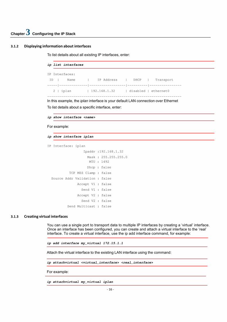
3.1.2 Displaying information about interfaces
To list details about all existing IP interfaces, enter:
ip list interfaces
IP Interfaces:
ID | Name | IP Address | DHCP | Transport
-----|--------------|------------------|----------|----------------
2 | iplan | 192.168.1.32 | disabled | ethernet0
------------------------------------------------------------------- In this example, the iplan interface is your default LAN connection over Ethernet
To list details about a specific interface, enter:
ip show interface <name>
For example:
ip show interface iplan
IP Interface: iplan
Ipaddr :192.168.1.32
Mask : 255.255.255.0 MTU : 1492
Dhcp : false
TCP MSS Clamp : false
Source Addr Validation : false
Accept V1 : false
Send V1 : false
Accept V2 : false
Send V2 : false
Send Multicast : false
3.1.3 Creating virtual interfaces
You can use a single port to transport data to multiple IP interfaces by creating a ‘virtual’ interface. Once an interface has been configured, you can create and attach a virtual interface to the ‘real’ interface. To create a virtual interface, use the ip add interface command, for example:
ip add interface my_virtual 172.15.1.1
Attach the virtual interface to the existing LAN interface using the command:
ip attachvirtual <virtual_interface> <real_interface>
For example:
ip attachvirtual my_virtual iplan
Chapter 3 Configuring the IP Stack
‐ 17 ‐
The virtual interface uses the transport and port configuration already attached to the ‘real’ interface. At the ip list interfaces table, the Transport name of the virtual interface is displayed as [real_interface].
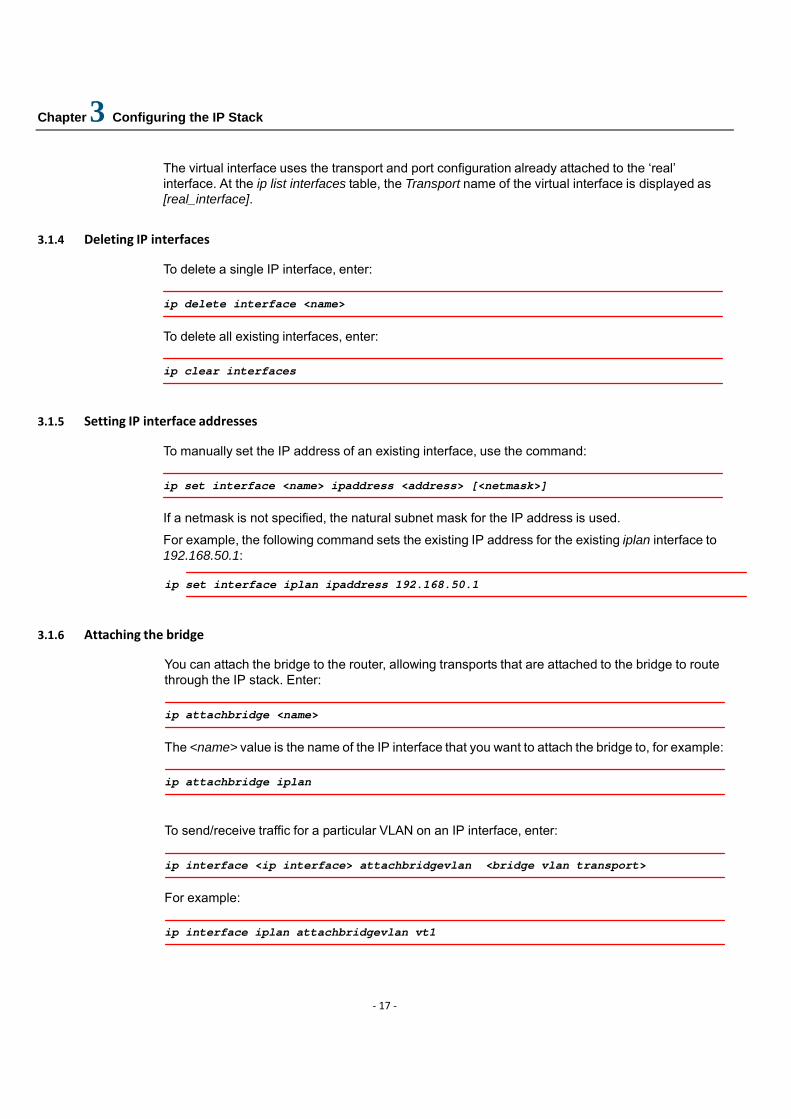
3.1.4 Deleting IP interfaces
To delete a single IP interface, enter:
ip delete interface <name>
To delete all existing interfaces, enter:
ip clear interfaces
3.1.5 Setting IP interface addresses
To manually set the IP address of an existing interface, use the command:
ip set interface <name> ipaddress <address> [<netmask>]
If a netmask is not specified, the natural subnet mask for the IP address is used.
For example, the following command sets the existing IP address for the existing iplan interface to 192.168.50.1:
ip set interface iplan ipaddress 192.168.50.1
3.1.6 Attaching the bridge
You can attach the bridge to the router, allowing transports that are attached to the bridge to route through the IP stack. Enter:
ip attachbridge <name>
The <name> value is the name of the IP interface that you want to attach the bridge to, for example:
ip attachbridge iplan
To send/receive traffic for a particular VLAN on an IP interface, enter:
ip interface <ip interface> attachbridgevlan <bridge vlan transport>
For example:
ip interface iplan attachbridgevlan vt1
Chapter 3 Configuring the IP Stack
‐ 18 ‐
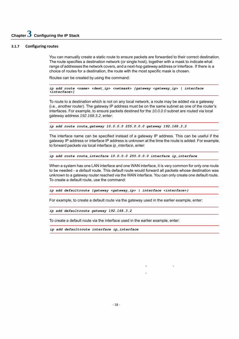
3.1.7 Configuring routes You can manually create a static route to ensure packets are forwarded to their correct destination. The route specifies a destination network (or single host), together with a mask to indicate what range of addresses the network covers, and a next-hop gateway address or interface. If there is a choice of routes for a destination, the route with the most specific mask is chosen.
Routes can be created by using the command:
ip add route <name> <dest_ip> <netmask> {gateway <gateway_ip> | interface <interface>}
To route to a destination which is not on any local network, a route may be added via a gateway (i.e., another router). The gateway IP address must be on the same subnet as one of the router’s interfaces. For example, to ensure packets destined for the 10.0.0.0 subnet are routed via local gateway address 192.168.3.2, enter:
ip add route route_gateway 10.0.0.0 255.0.0.0 gateway 192.168.3.2
The interface name can be specified instead of a gateway IP address. This can be useful if the gateway IP address or interface IP address is unknown at the time the route is added. For example, to forward packets via local interface ip_interface, enter:
ip add route route_interface 10.0.0.0 255.0.0.0 interface ip_interface
When a system has one LAN interface and one WAN interface, it is very common for only one route to be needed - a default route. This default route would forward all packets whose destination was unknown to a gateway router reached via the WAN interface. You can only create one default route. To create a default route, use the command:
ip add defaultroute {gateway <gateway_ip> | interface <interface>}
For example, to create a default route via the gateway used in the earlier example, enter:
ip add defaultroute gateway 192.168.3.2
To create a default route via the interface used in the earlier example, enter:
ip add defaultroute interface ip_interface
Chapter 3 Configuring the IP Stack
‐ 19 ‐
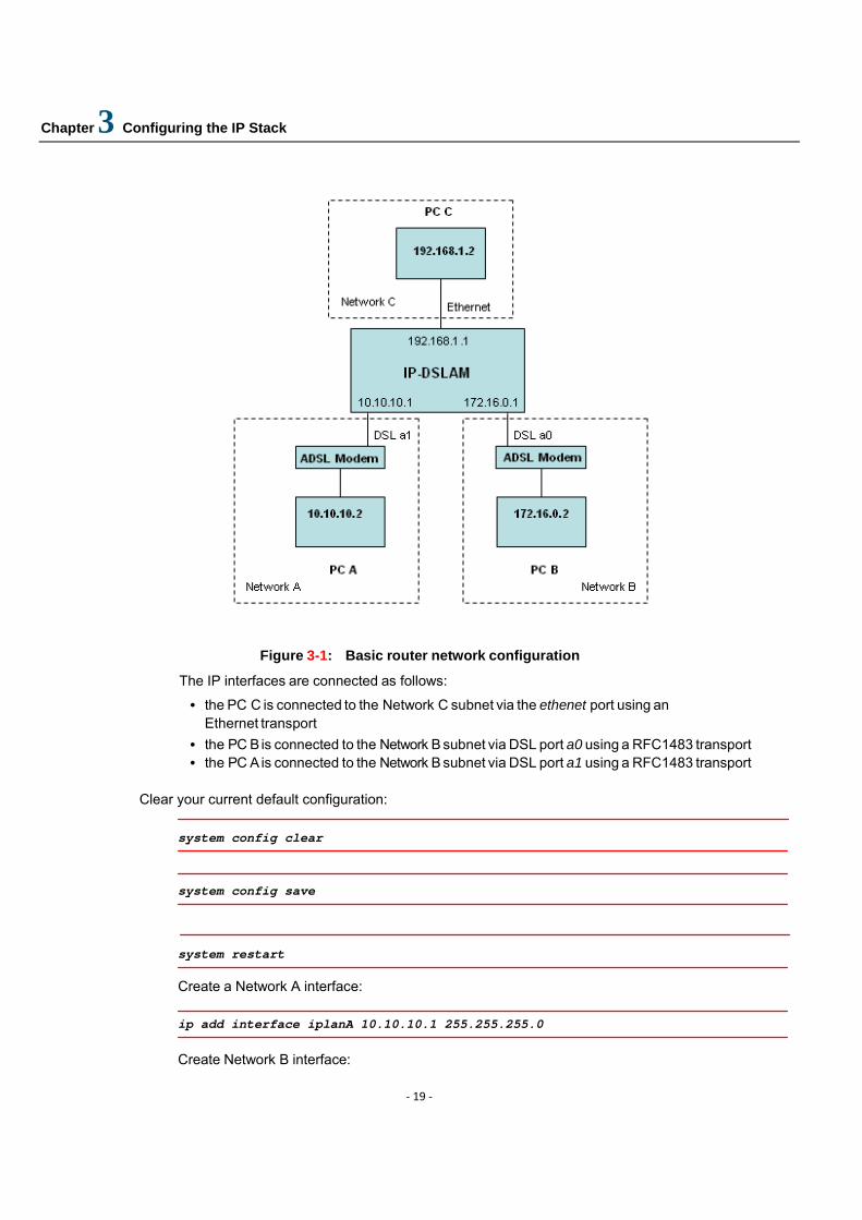
Figure 3-1: Basic router network configuration
The IP interfaces are connected as follows:
• the PC C is connected to the Network C subnet via the ethenet port using an Ethernet transport
• the PC B is connected to the Network B subnet via DSL port a0 using a RFC1483 transport • the PC A is connected to the Network B subnet via DSL port a1 using a RFC1483 transport
Clear your current default configuration:
system config clear
system config save
system restart Create a Network A interface:
ip add interface iplanA 10.10.10.1 255.255.255.0
Create Network B interface:
Chapter 3 Configuring the IP Stack
‐ 20 ‐
ip add interface iplanB 172.16.0.1 255.255.255.255
Create a Network C interface:
ip add interface iplanC 192.168.1.1 255.255.255.0
Create transports for each of the IP interfaces:
ethernet add transport eth0 ethernet0
rfc1483 add wb0 a0 0 35
rfc1483 add wb1 a1 0 35 Attach the transports to their respective IP interfaces:
ip attach iplanA wb1
ip attach iplanB wb0
ip attach iplanC eth0
Check your interface configuration using the ip list interfaces command. Add router:
ip add route lanC 192.168.1.0 255.255.255.0 interface iplanC
ip add route lanB 172.16.0.0 255.255.255.0 interface iplanB
ip add route lanA 10.10.10.0 255.255.255.0 interface iplanA
Chapter 4 Configuring the bridge
‐ 21 ‐
4 Configuring the Bridge
This chapter describes how to configure the D-bridge (802.1D Bridge) and the Q-bridge (802.1Q Bridge).
4.1 Introduction
The DSLAM bridge operates in either the D-bridge mode or the Q-bridge mode. The Q-bridge (802.1Q bridge) is an extension to the 802.1D bridge (D-bridge). As specified in IEEE Standard 802.1Q-1998 and IEEE Standard 802.1D-1998, the principle elements of Bridge operation are:
• reception, filtering and transmission of frames between the separate MACs of the Bridged interfaces connected to a device’s ports.
• maintenance of the information needed to make filtering and relaying decisions. • management of the above
DSLAM bridge elements are managed via the CLI and EmWeb. Along with the basic 802.1D functionality that allows you to bridge network traffic between different network ports, Q-bridge can also be configured to separate traffic into Virtual LANs (VLANs) and to prioritize incoming traffic using frame header tags.
In addition, the bridge can be configured to support IGMP snooping functionality. IGMP snoop enables forwarding of multicast traffic intelligently instead of flooding all ports with multicast packets. This leads to efficient use of network bandwidth. IGMP Snoop is available in both Q-bridge and D- bridge mode. For details of IGMP Snoop and its configuration, refer to IGMP Snoop Support chapter.
This chapter contains the following sections:
• Overview of Q-bridge suppor; describes the functionality supported including frame header tags, 802.1P and VLAN learning mechanisms.
• Basic D bridge configuration; provides basic D-bridge configuration information. • Q-bridge CLI commands; describes the main bridge commands that you will use to
configure VLANs. • Example Q-bridge configurations; describes typical VLAN network configurations. • IGMP Snoop Support ; provides an overview of IGMP Snoop, its benefits and an
example configuration.

Chapter 4 Configuring the bridge
‐ 22 ‐
4.2 Overview of Q-bridge support
The Q-bridge supports the following functionality:
• Can support more than 72 Bridge ports • Performs source address learning based on source MAC address and VID • Maintains a static filtering database based on destination MAC address and VID • Maintains a static filtering database based on source MAC address and VID • Performs filtering and forwarding of frames based on the filtering database • Maintains static VLAN registration entries and forwarding frames based on those entries • Supports a hybrid VLAN learning mechanism for unicast packets, thus enabling both
Independent VLAN Learning (IVL) and Shared VLAN Learning (SVL) • Supports both independent and hybrid VLAN learning mechanisms for multicast frames • Provides support for tagged as well as untagged frames, and making tagging decisions for
outgoing frames based on port properties • Performs packet prioritization • Supports 802.1P which provides a method for specifying how prioritization should occur within
a MAC-layer bridge • Performs age-out of dynamic entries in the filtering database • Provides both command-based and graphical interfaces for management and configuration of
the bridge 4.2.1 Frame header tags
Forwarding, filtering and prioritizing decisions are based on VLAN tags specified in incoming frames. Frames can fall into one of the following categories:
• vlan-tagged; a tag header is attached to the frame after the source MAC address field or the Routing Information field. The tag header contains a VLAN ID and a prioritization field.
• priority-tagged; a tag header is attached to the frame after the source MAC address field or the Routing Information field. The tag header contains prioritization information and a null VLAN ID.
• untagged; there is no tag header attached to the frame
4.2.2 802.1P support
802.1P defines the prioritization field of the VLAN tag, which adds a 32-bit tag header after a frame’s normal destination and source address header information. The DSLAM schedules packets based on the traffic class value set in each frame. The user priority in the incoming frame header is mapped to a regenerated priority value in the outgoing frame header. The regenerated priority value is mapped to a traffic class value .
Eight levels (values 0-7) of priority are defined. Value 7 is the highest priority and 0 is the lowest. Incoming packets are buffered in multiple queues based on their priority.
The Priority Queuing service discipline is used to provide better treatment to higher priority frames compared with lower priority frames. A lower priority queue is only served if the queues of higher priority levels are not backlogged. This scheme may cause starvation to low priority frames if there is a continuous flow of high priority frames.
Chapter 4 Configuring the bridge
‐ 23 ‐
Incoming frames are buffered in the default priority-enabled interface of the bridge process.
4.2.3 VLAN Learning Mechanisms
You can configure the bridge to support the following VLAN learning mechanisms:
• Independent VLAN Learning (IVL)- Using IVL, the Learning Process and Filtering Database can be configured so that if an individual MAC address is learned in one VLAN, that learned information is not used in forwarding decisions taken for that address relative to any other VLAN in the system. This is achieved by including information from each VLAN in distinct Filtering Databases.
• Independent VLAN Learning (IVL)/ Shared VLAN Learning (SVL) - Two learning mechanisms are supported. Using SVL, the Learning Process and Filtering Database can be configured so that if an individual MAC address is learned in one VLAN, that learned information is used in forwarding decisions taken for that address relative to all other VLAN in the given set. This is achieved by including learned info from a number of VLANs in the same Filtering Database.
Unicast learning supports SVL/IVL (referred to as the Hybrid VLAN Mechanism in ISOS) - which supports multiple Filtering Databases and allows you to define the grouping of VLANs to Filtering Databases. For IVL learning, multiple Filtering Databases are supported and you can define the each VLAN using an independent Filtering Database. For SVL learning, a single Filtering Database is supported and you can define all VLANs to use the same Filtering Database.
Multicast learning supports the same mechanisms supported by unicast learning, but you can also configure the bridge module file to support only IVL (without SVL) so that learning for each VLAN takes place in an independent Filtering Database.
4.3 Basic bridge configuration
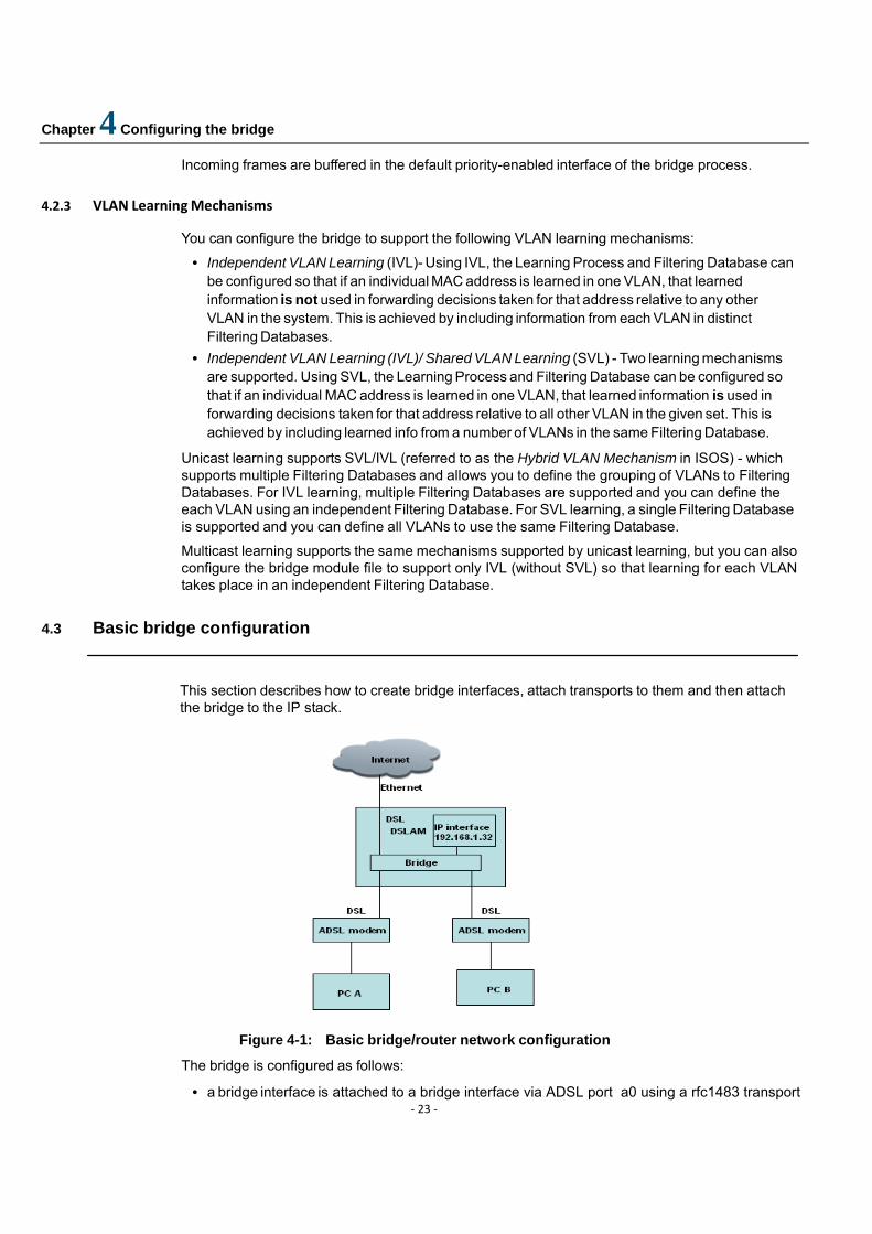
This section describes how to create bridge interfaces, attach transports to them and then attach the bridge to the IP stack.
Figure 4-1: Basic bridge/router network configuration
The bridge is configured as follows:
• a bridge interface is attached to a bridge interface via ADSL port a0 using a rfc1483 transport
Chapter 4 Configuring the bridge
‐ 24 ‐
• a bridge interface is attached to a bridge interface via ADSL port a1 using a rfc1483 transport • a bridge interface is connected to the Internet via Ethernet port ethernet0 using an Ethernet
transport • the bridge is attached to the IP stack via the IP LAN interface so that the dslam can be
management by ip address
Clear your current default configuration:
system config clear
system config save
system restart
Create a IP interface:
ip add interface iplan 192.168.1.32 255.255.255.0 : Bridge interfaces are created using the command:
bridge add interface <name>
Create a bridge interface
bridge add interface uplink
Ethernet transport are created using the command:
ethernet add transport <name> ethernet0
Create a ethernet transport
ethernet add transport eth0 ethernet0
Transports are attached to the bridge using the command:
bridge attach <interface> <transport>
Attach the Ethernet transport to the uplink bridge interface:
bridge attach uplink eth0
Create a bridge interface and an Rfc1483 transport, then attach them: Create bridge interfaces:
bridge add interface wan0
bridge add interface wan1

Chapter 4 Configuring the bridge
‐ 25 ‐
Rfc1483 transport are created using the command:
Rfc1483 add transport <name> <adsl port> <vpi> <vci> <llc/vcum> <bridged/routed>
Create rfc1483 transports
rfc1483 add transport wb0 a0 0 35 llc bridged
rfc1483 add transport wb1 a0 0 35 llc bridged
Attache the rfc1483 transport to bridge
bridge attach wan0 wb0
bridge attach wan0 wb0
The bridge is attached to the router using the command:
ip attachbridge <ip_interface>
Attach the bridge to the LAN IP interface:
ip attachbridge iplan
Check the bridge by entering:
bridge list interfaces
ID: 1 Name: wan0
Filter| PVID | Accept | Ingress | User | Transport Type | | FrameType | Filtering | Prio | ------|-------|-----------|-----------|-------|----------------------------- All | 1 | ALL | disabled | 0 | wb0
ID: 2 Name: wan1
Filter| PVID | Accept | Ingress | User | Transport Type | | FrameType | Filtering | Prio | ------|-------|-----------|-----------|-------|----------------------------- All | 1 | ALL | disabled | 0 | wb1
----------------------------------------------------------------------------
For detailed information about a single bridge interface, use the command:
bridge show interface <name>
For example:
bridge show interface ethernet0
bridge interface: ethernet0

Chapter 4 Configuring the bridge
‐ 26 ‐
Name: ethernet0
Filter Type: All
Port Filter: All
PVID: 1
Acceptable Frame Type: ALL
Ingress Filtering: ENABLED
user Priority: 0
Transport: ethernet0
Note that the bridge list interfaces and bridge show interface example outputs displayed above are for an image which has the Q-bridge option included. If you have not included the Q-bridge option, a subset of this information is displayed.
4.4 Q-bridge CLI commands
This section describes the basic Q-bridge CLI commands required to create and configure VLANs. They allow you to:
1. Create a Virtual LAN; s 2. Create a VLAN port and set it to forward either tagged or untagged frames; 3. Set ingress filter rules for vlan-tagged frames; 4. Configure the Bridge interface to accept or reject untagged incoming frames; 5. Create forwarding rules and filters for unicast or multicast frames; 6. Map the user priorities of incoming frames to regenerated priorities, then map regenerated
priorities to traffic classes; 7. Create bridge VLAN transports, each for a particular VLAN, and associates IP interfaces to the
bridge VLAN transports;
4.4.1 Creating VLANs
bridge add vlan <name> <vlanid> <fdb>
Note that the VLAN ID is always unique to each specific VLAN. You can create a single default VLAN and/or one or more user-defined VLANs. A default VLAN allows forwarding of untagged frames. To create a default VLAN, you MUST enter:
bridge add vlan DefaultVlan 1 DefaultFdb
Note that you cannot create a user-defined VLAN by entering the same VLAN ID of the default VLAN (of value 1), because it is reserved for the default VLAN. However, user-defined VLANs may use the same filtering database - DefaultFdb. A User-defined VLAN allows you to specify the name, ID and Filtering Database (FDB) name. Specifying a Filtering Database for the first time, automatically creates the database and adds it to the list displayed by the bridge list fdbs command. For example:
bridge add vlan vlan2 2 Qbridge

Chapter 4 Configuring the bridge
‐ 27 ‐
To check the Filtering Databases, enter:
bridge list fdbs
Filtering Databases Statistics:
ID|FDB Name |FID|Num VLANs|Num Entries|Num O/F Discard|Type
---------------------------------------------------------------
1|DefaultFdb| 0 |1 |0 |0 |static
2|Qbridge | 1 |1 |0 |0 |static
---------------------------------------------------------------
4.4.2 Creating VLAN ports
Once you have created a VLAN, you must add VLAN interfaces to it and specify whether the interfaces should forward untagged or tagged frames on those interfaces. VLAN interfaces are created using the command:
bridge add vlaninterface <name> {tagged|untagged} <interfacename>
The <name> is the name of the VLAN created using the bridge add vlan command. The <interfacename> is the name of the bridge interface that has a valid transport/port attached to it. The interface must be defined as one of the following:
• a tagged interface; will always transmit tagged packets for the VLAN • an untagged interface; will always transmit untagged packets for the VLAN
For example, if you want to add the ethernet0 and a1 ports to vlan2’s list of tagged egress interfaces, enter:
bridge add vlaninterface vlan2 tagged uplink
bridge add vlaninterface vlan2 tagged wan1
To list VLANs and check which interfaces are tagged and untagged for each one, enter:
bridge list vlans
VLANs:
ID | VLAN ID | VLAN Name | FDB Name | Type
---------------------------------------------------
1 | 2 | vlan2 | Qbridge | static
Tagged Interfaces : uplink wan1
Untagged Interfaces:
You are not allow to add VLAN interfaces to a default VLAN. For the DefaultVlan, all existing interfaces attached to the bridge via transports are already automatically configured as untagged interfaces. The bridge interfaces subsequently created are also added as untagged interfaces to the default VLAN.
Chapter 4 Configuring the bridge
‐ 28 ‐
4.4.3 Ingress filtering vlan‐tagged frames
You can set an ingress rule on bridge interfaces in order to filter vlan-tagged frames based on their VLAN ID. The VLAN ID of every vlan-tagged frame received by an interface is checked. If the ID specified in the frame matches a VLAN, and if the interface that received the frame is listed in that VLAN’s egress interface list, the frame is accepted. If the ID does not match or the interface is not in the egress interface list, the frame is discarded. This rule is disabled by default to allow incoming frames regardless of their VLAN ID.
Configure ingress filtering using the command:
bridge set interface <name> ingressfiltering {disable|enable}
For example, the following commands ensure that only vlan-tagged frames with a VLAN ID of 2 are accepted by the lan interface:
bridge set interface lan ingressfiltering enable
4.4.4 Accepting/rejecting incoming frames
Configure the bridge interfaces to determine whether they can accept only vlan-tagged frames or accept all incoming frames (vlan-tagged, priority-tagged and untagged) using the following command:
bridge set interface <name> acceptframetype {acceptall|accepttaggedonly}
In order for a bridge interface to accept all frames, each frame must have a valid VLAN ID. Priority- tagged and untagged frames do not have VLAN IDs, so they are assigned a Port VLAN ID (PVID) instead. By default, bridge interfaces accept all frames and the default PVID assigned to frames is 1.
There is no need to change the default PVID if you want to send the untagged traffic as untagged on all ports in the Default VLAN. If you want to send all untagged traffic to a particular VLAN, change the PVID so that it corresponds with the VLAN ID by entering:
bridge set interface {name|number} pvid <pvid>
For example, use the following default setting:
bridge set interface lan acceptframetype acceptall
bridge set interface wan acceptframetype acceptall
then set the correct PVID as follows:
bridge set interface lan pvid 2
bridge set interface wan pvid 2
If you want a bridge interface to accept only vlan-tagged frames, all priority-tagged and untagged
Chapter 4 Configuring the bridge
‐ 29 ‐
frames that do not carry a VLAN ID (i.e., untagged and priority-tagged frames) are discarded. The following commands set the lan and wan interfaces to accept tagged frames only:
bridge set interface lan acceptframetype accepttaggedonly
bridge set interface wan acceptframetype accepttaggedonly
4.4.5 Forwarding and filtering frames
The forwarding process determines which frames should be forwarded between interfaces on the bridge. Different filters can be applied to unicast and multicast frames respectively.
4.4.5.1 Forwarding unicast frames
Create a filter for the destination MAC address of unicast frames. If the destination MAC address of an incoming unicast frame matches the address set in this entry, the frame is forwarded to the egress interface for this entry. To create a filter, enter:
bridge add ucastentry dest <name> <fdbname> <macaddress>
Create a similar filter for the source MAC address and source interface. If the source MAC address of an incoming unicast frame and the source interface that receives it match the address/interface set in this entry, the frame is forwarded to the egress interfaces in the entry. To create a filter, enter:
bridge add ucastentry src <name> <fdbname> <macaddress> <recvinterface>
Add an interface to the source or destination MAC filtering entry that you created using the previous two example commands. Enter:
bridge add ucastinterface <entryname> <fdbname> egress <interfacename>
4.4.5.2 Forwarding multicast frames
You can create a Forward All Group for an existing Filtering Database. The interfaces added to this group are the interfaces that all multicast frames will be forwarded to, in addition to the interfaces added using the bridge add mcastentry command (described later in this section).
bridge add fwdallinterface independent <vlanname> <interfacename>
bridge add fwdallinterface shared <fdbname> <interfacename>
If you specify the independent option, learning for each VLAN is separate, therefore you only need to specify one VLAN name. If you specify the shared option, learning is based on the VLANs that are grouped into a Filtering Database. For example, if you set the multicast learning mechanism to IVM in the bridge.module file, enter:
bridge add fwdallinterface independent vlan2
You can also create a Forward Unregistered Group for an existing VLAN. The interfaces added to this group are the interfaces that multicast frames will be forwarded to if their destination MAC address is not present in the Filtering Database entry. You can specify whether the interface uses

Chapter 4 Configuring the bridge
‐ 30 ‐
the independent or shared VLAN learning mechanism, depending on the learning mechanism set in the bridge.module file. To add an interface to this group, enter one of the following:
bridge add fwdunreginterface independent <vlanname> <interfacename>
bridge add fwdunreginterface shared <fdbname> <interfacename>
Create a filter for the MAC address of multicast frames. If the MAC address of an incoming frame matches the address set in this filter, the frame is forwarded to all interfaces added to the specified multicast entry’s egress interface list (see the bridge add mcastport command). You can specify whether the interface uses the independent or shared VLAN learning mechanism. To create a filter, enter one of the following:
bridge add mcastentry independent <name> <vlanname> <mac>
bridge add mcastentry shared <name> <fdbname> <mac>
For example:
bridge add mcastentry independent filter1 vlan2 01:00:00:00:00:0
Add an interface to the egress interface list of the multicast entry. This list is used by the filter entries previously created. You can specify whether the interface uses the independent or shared VLAN learning mechanism. To add an interface to the egress list, enter:
bridge add mcastinterface independent <entryname> <vlanname> egress <interfacename>
bridge add mcastinterface shared <entryname> <fdbname> egress <interfacename>
For example:
bridge add mcastinterface independent filter1 vlan2 egress lan
4.4.5 Prioritizing frames
You must map the priority levels of incoming frames to regenerated priority levels. Once the priority level of an incoming frame is detected on the specified bridge interface, the Q-bridge will replace it with the regenerated priority level mapped to that particular user priority. The regenerated level is set in the VLAN tag of outgoing frames.
Regenerated priority levels can be set to any value between 0-7, where 7 is the highest priority and 0 is the lowest. To set the regenerated priority mappings, use the following command:
bridge set interface <name> regenpriority <pri0> <pri1> <pri2> <pri3> <pri4> <pri5> <pri6> <pri7>
For example:
Chapter 4 Configuring the bridge
‐ 31 ‐
bridge set interface lan regenpriority 0 0 0 0 5 6 7 7
According to the mapping set in this command, any incoming frame with a user priority of 0-3 will be replaced by regenerated priority 0, and priorities 4, 5, 6 and 7 will be replaced by regenerated priorities 5, 6, 7 and 7 respectively.
If your interface is configured to accept untagged frames, you must also configure the user priority that should be assigned to those frames, using the following command:
bridge set interface <name> defaultuserpriority <defaultpriority>
The regenerated levels are then mapped to traffic class values in the outgoing frame. Traffic class values can be set to any value between 0-7, where 7 is the highest class and 0 is the lowest. This value is used by the Scheduler device to prioritize frames for transmission. Traffic class mapping is disabled by default. To enable it, enter:
bridge set trafficclassstatus enable
Now map the regenerated priority levels to their traffic class values, using the following command:
bridge set interface <name> trafficclassmap <pri0> <pri1> <pri2> <pri3> <pri4> <pri5> <pri6> <pri7>
For example:
bridge set interface wan trafficclassmap 0 0 0 0 1 1 1 1
According to this mapping, any outgoing frame with a regeneration priority between 0-3 will be assigned a traffic class of 0, and any outgoing frame with a regeneration priority between 4-7 will be assigned traffic class 1. Traffic class 1 will be given higher priority over traffic class 0.
4.4.6 Bridge VLAN transport
Bridge VLAN transport which allows the user to create bridge VLAN transports, each for a particular VLAN, and associates IP interfaces to the bridge VLAN transports. Each bridge VLAN transport shall be associated with a unique VLAN Id and a single IP interface. All the packets sent by IP through a bridge VLAN transport will be tagged with the VLAN Id associated with it. Similarly, the tagged IP traffic received by the bridge will be sent to IP on the bridge VLAN transport associated with the VLAN Id in the packet.
NOTE: The IP stack still sends/receives untagged packets to/from the bridge. It is the bridge that tags the packet appropriately and forwards on the VLAN interfaces.
To associate an IP interface to a VLAN, first create a bridge VLAN transport using the following command:
NOTE: A VLAN with the same VLAN Id should be added to the system before running the add command.
Chapter 4 Configuring the bridge
‐ 32 ‐
bridgevlan add transport <name> <vlanID>
For example:
bridgevlan add transport vt1 7
According to this command, a new bridge VLAN transport is created with VLAN Id 7.
To associate an IP interface with a VLAN, attach the interface with a bridge VLAN transport. Use the following command:
ip interface <ip interface> attachbridgevlan <vlan transport>
For example:
ip interface iplan attachbridgevlan vt1
According to this command, the IP interface ip1 will send/receive packets with the VLAN Id corresponding to the transport vt1, which is 7.
NOTE: Only one bridge VLAN transport can be associated with an IP interface, i.e. one IP interface cannot send/receive traffic for multiple VLANs.
4.5 Example Q-bridge configurations
The configurations described in this section allow you to:
• Achieve LAN isolation; • Create VLANs across multiple switches; • Enable user mobility;
4.5.1 LAN isolation using VLANs
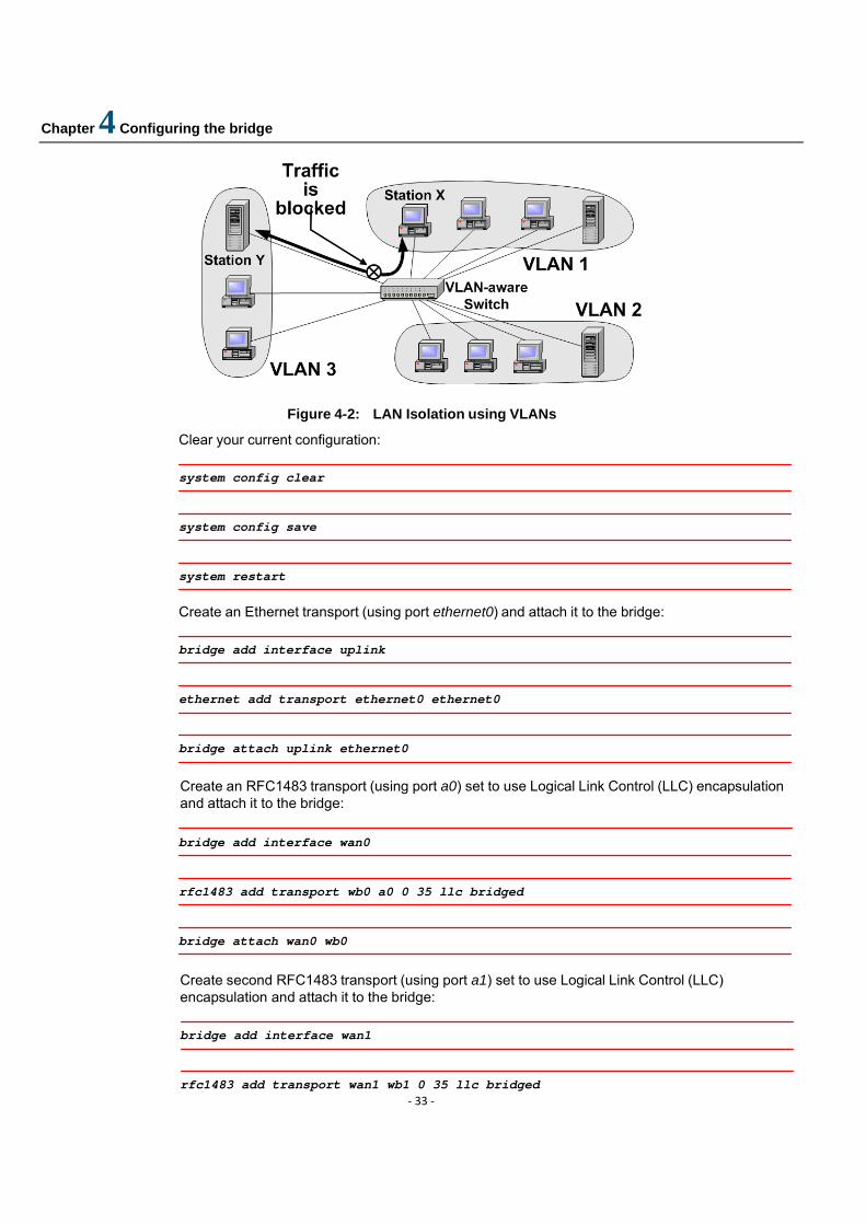
You can achieve traffic isolation and security by isolating different networks for broadcast and multicast traffic. For example, in the figure below, broadcast and multicast traffic is blocked between VLANs (e.g., between station X and station Y), even though every station is connected to the same switch.
Chapter 4 Configuring the bridge
‐ 33 ‐
Figure 4-2: LAN Isolation using VLANs
Clear your current configuration:
system config clear
system config save
system restart
Create an Ethernet transport (using port ethernet0) and attach it to the bridge:
bridge add interface uplink
ethernet add transport ethernet0 ethernet0
bridge attach uplink ethernet0
Create an RFC1483 transport (using port a0) set to use Logical Link Control (LLC) encapsulation and attach it to the bridge:
bridge add interface wan0
rfc1483 add transport wb0 a0 0 35 llc bridged
bridge attach wan0 wb0
Create second RFC1483 transport (using port a1) set to use Logical Link Control (LLC) encapsulation and attach it to the bridge:
bridge add interface wan1
rfc1483 add transport wan1 wb1 0 35 llc bridged
Chapter 4 Configuring the bridge
‐ 34 ‐
bridge attach wan1 wb1
Create two VLANs called vlan2 and vlan3 both using the same Filtering Database:
bridge add vlan vlan2 2 Qbridge
bridge add vlan vlan3 3 Qbridge
Add two VLAN interfaces to vlan2. The bridge interfaces wan0 and wan1 (attached to ports a0 and a1) are configured to forward tagged packets:
bridge add vlaninterface vlan2 tagged wan0
bridge add vlaninterface vlan2 tagged uplink
Add two VLAN interfaces to vlan3. The bridge interfacesuplink (attached to ports ethernet1 and wan respectively) are configured to forward tagged packets :
bridge add vlaninterface vlan3 tagged uplink
bridge add vlaninterface vlan3 tagged wan1
Traffic isolation now exists between wan0 and wan1 interfaces:
• VLAN2 tagged traffic flows between wan0 and uplink interfaces • VLAN3 tagged traffic flows between wan1 and uplink interfaces
Chapter 4 Configuring the bridge
‐ 35 ‐
4.5.2 VLANs Spanning Multiple Switches
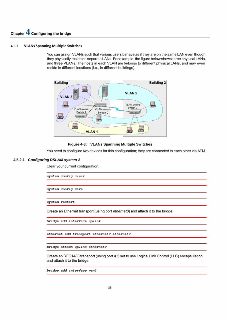
You can assign VLANs such that various users behave as if they are on the same LAN even though they physically reside on separate LANs. For example, the figure below shows three physical LANs, and three VLANs. The hosts in each VLAN are belongs to different physical LANs, and may even reside in different locations (i.e., in different buildings).
Figure 4-3: VLANs Spanning Multiple Switches
You need to configure two devices for this configuration; they are connected to each other via ATM.
4.5.2.1 Configuring DSLAM system A
Clear your current configuration:
system config clear
system config save
system restart
Create an Ethernet transport (using port ethernet0) and attach it to the bridge:
bridge add interface uplink
ethernet add transport ethernet0 ethernet0
bridge attach uplink ethernet0
Create an RFC1483 transport (using port a1) set to use Logical Link Control (LLC) encapsulation and attach it to the bridge:
bridge add interface wan1
Chapter 4 Configuring the bridge
‐ 36 ‐
rfc1483 add transport wb1 a1 0 35 llc bridged
bridge attach wan1 wb1
Create a VLAN called vlan2:
bridge add vlan vlan2 2 Qbridge
Add two VLAN interfaces to vlan2. The bridge interfaces uplink and wan1 (ethernet0 and a0 respectively) are configured to forward tagged packets:
bridge add vlaninterface vlan2 tagged uplink
bridge add vlaninterface vlan2 tagged uplink
4.5.2.2 Configuring DSLAM system B
This configuration is identical to the configuration for DSLAM System B:
system config clear
system config save
system restart
bridge add interface uplink
ethernet add transport ethernet0 ethernet0
bridge attach uplink ethernet0
bridge add interface wan0
rfc1483 add transport wan0 a0 0 35 llc bridged
bridge attach wan1 wan0
bridge add vlan vlan2 2 Qbridge
bridge add vlaninterface vlan2 tagged uplink
Chapter 4 Configuring the bridge
‐ 37 ‐
bridge add vlaninterface vlan2 tagged wan0 vlan2 now spans DSLAM systems A and B.
4.5.3 Traffic prioritization
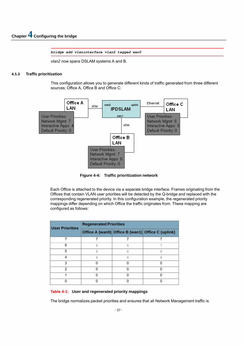
This configuration allows you to generate different kinds of traffic generated from three different sources; Office A, Office B and Office C:
Figure 4-4: Traffic prioritization network
Each Office is attached to the device via a separate bridge interface. Frames originating from the Offices that contain VLAN user priorities will be detected by the Q-bridge and replaced with the corresponding regenerated priority. In this configuration example, the regenerated priority mappings differ depending on which Office the traffic originates from. These mapping are configured as follows:
Regenerated Priorities User Priorities
Office A (wan0) Office B (wan1) Office C (uplink) 7 7 7 7 6 6 6 7 5 6 6 6 4 6 6 6 3 0 0 0 2 0 0 0 1 0 0 0 0 0 0 0
Table 4-1: User and regenerated priority mappings The bridge normalizes packet priorities and ensures that all Network Management traffic is
Chapter 4 Configuring the bridge
‐ 38 ‐
transmitted with priority 7, and Interactive traffic is transmitted with priority 6.
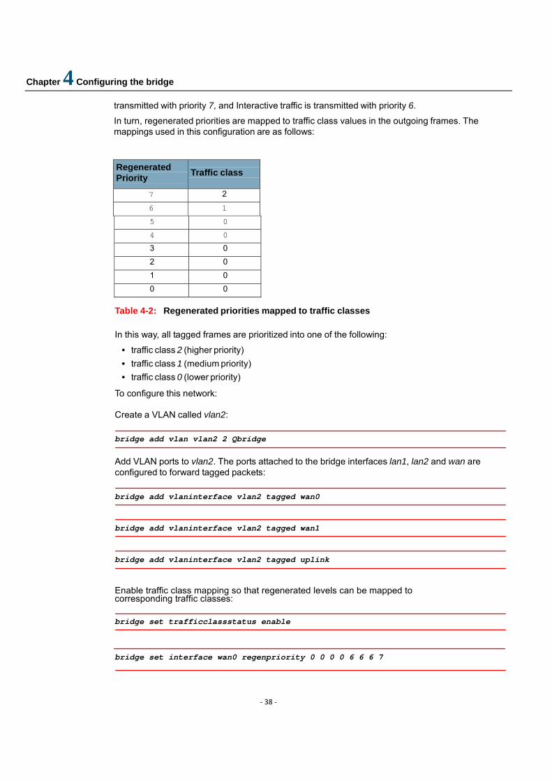
In turn, regenerated priorities are mapped to traffic class values in the outgoing frames. The mappings used in this configuration are as follows:
Regenerated Priority
Traffic class
7 2 6 1 5 0 4 0 3 0 2 0 1 0 0 0
Table 4-2: Regenerated priorities mapped to traffic classes In this way, all tagged frames are prioritized into one of the following:
• traffic class 2 (higher priority) • traffic class 1 (medium priority) • traffic class 0 (lower priority)
To configure this network:
Create a VLAN called vlan2:
bridge add vlan vlan2 2 Qbridge
Add VLAN ports to vlan2. The ports attached to the bridge interfaces lan1, lan2 and wan are configured to forward tagged packets:
bridge add vlaninterface vlan2 tagged wan0
bridge add vlaninterface vlan2 tagged wan1
bridge add vlaninterface vlan2 tagged uplink
Enable traffic class mapping so that regenerated levels can be mapped to corresponding traffic classes:
bridge set trafficclassstatus enable
bridge set interface wan0 regenpriority 0 0 0 0 6 6 6 7
Chapter 4 Configuring the bridge
‐ 39 ‐
bridge set interface wan1 regenpriority 0 0 0 0 6 6 6 7
bridge set interface uplink regenpriority 0 0 0 0 6 6 7 7
bridge set interface lan1 trafficclassmap 0 0 0 0 0 0 1 2
bridge set interface lan2 trafficclassmap 0 0 0 0 0 0 1 2
bridge set interface wan trafficclassmap 0 0 0 0 0 0 1 2
You can now generate packets from each Office and check that user priorities are mapped to traffic classes as follows:
• Default priority traffic maps to traffic class 0 • Interactive traffic maps to traffic class 1 • Network Management traffic maps to traffic class 2
Chapter 4 Configuring the bridge
‐ 40 ‐
4.6 IGMP Snoop Support
4.6.1 Overview
An IGMP Snoop switch provides the benefit of conserving bandwidth on those segments of the network where no node has expressed interest in receiving packets addressed to the multicast group address. This is in contrast to the normal switch behavior where multicast traffic is typically forwarded on all interfaces.
The IGMP Snooping switch listens to IGMP reports, queries and leave messages sent between hosts and a multicast router, to identify the interfaces that are members of multicast groups. Based on this information it adds/deletes multicast entries from its filtering database, ensuring that multicast traffic is only forwarded to interfaces identified as members of the specific multicast group.
In ISOS, IGMP Snoop is implemented in two modes - Proxy and Snoop-only, with 'Snoop-only' being the default mode. The 'Proxy mode' is supported by means of IGMP proxy-reporting, where the reports received from the downstream hosts are summarized and then the switch reports its own state in response to the upstream queries from multicast routers. The switch also acts as a Querier, generating queries periodically on the downstream interfaces. The 'Snoop only' mode is implemented by snooping through the IGMP packets and forwarding the IGMP packets received on the upstream interfaces to all other interfaces. As the queries received from the upstream interfaces are forwarded to the downstream interfaces, periodic queries are not generated, unlike the proxy mode. The IGMP packets received on a downstream interface are also forwarded to all the upstream interfaces.
IGMP Snoop also supports two leave processing modes for each bridge interface - Fast and Normal, with 'Normal' being the default mode. In the 'Fast' mode of leave processing, on receiving a leave message on a downstream interface, IGMP Snoop shall simply delete the interface from the group membership information and the 'Leave' message is forwarded to the upstream interfaces. 'Fast' Mode for an interface shall be configured when it is known that there is only one host behind the interface. Fast leave processing helps to reduce the latency involved in removing an interface from the group membership information. In the 'Normal' mode of leave processing, on receiving a leave message on a downstream interface, IGMP snoop shall repeatedly generate group specific queries on the interface. Failure to receive any membership report in response shall result in deletion of the interface from the group membership information.

Chapter 4 Configuring the bridge
‐ 41 ‐
4.6.2 Benefits of IGMP Snoop in D‐bridge mode
In D-bridge, all multicast packets are treated like broadcast packets which are forwarded on all ports in the forwarding state. This results in less efficient utilization of network bandwidth as multicast traffic is forwarded on interfaces where no node has any interest in receiving the packet.
Figure 4-5: Multicast packets flooding without IGMP Snoop in D-bridge
IGMP snooping enables forwarding of multicast traffic intelligently, instead of flooding to all ports. Multicast packets that belong to a layer 2 multicast group are only forwarded to an interface if a host on that interface has expressed interest in the same group. This significantly reduces flooding of multicast data resulting in better utilization of network bandwidth and improved bridge performance.
4.6.3 Benefits of IGMP Snoop in Q‐bridge mode
In Q-bridge without IGMP Snoop, multicast packets are not forwarded unless the bridge is statically configured to forward multicast packets.In other words, multicast entries and their egress interface list need to be created through the CLI. Using the fwdall configuration to forward multicast packets on interfaces leads to multicast traffic for all multicast groups to be forwarded on these interfaces, which may not be desirable.
Chapter 4 Configuring the bridge
‐ 42 ‐
Figure 4-6: Reduced flooding with static configuration of Multicast Filtering Database in
Q-bridge
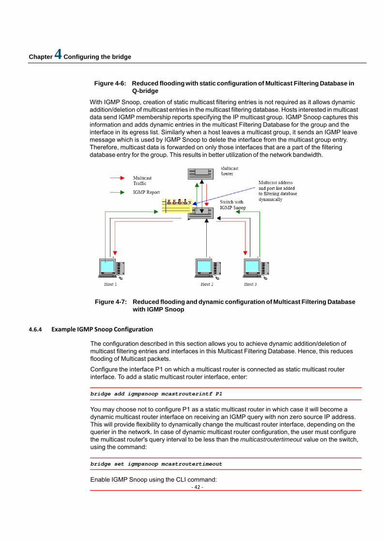
With IGMP Snoop, creation of static multicast filtering entries is not required as it allows dynamic addition/deletion of multicast entries in the multicast filtering database. Hosts interested in multicast data send IGMP membership reports specifying the IP multicast group. IGMP Snoop captures this information and adds dynamic entries in the multicast Filtering Database for the group and the interface in its egress list. Similarly when a host leaves a multicast group, it sends an IGMP leave message which is used by IGMP Snoop to delete the interface from the multicast group entry. Therefore, multicast data is forwarded on only those interfaces that are a part of the filtering database entry for the group. This results in better utilization of the network bandwidth.
Figure 4-7: Reduced flooding and dynamic configuration of Multicast Filtering Database with IGMP Snoop
4.6.4 Example IGMP Snoop Configuration
The configuration described in this section allows you to achieve dynamic addition/deletion of multicast filtering entries and interfaces in this Multicast Filtering Database. Hence, this reduces flooding of Multicast packets.
Configure the interface P1 on which a multicast router is connected as static multicast router interface. To add a static multicast router interface, enter:
bridge add igmpsnoop mcastrouterintf P1
You may choose not to configure P1 as a static multicast router in which case it will become a dynamic multicast router interface on receiving an IGMP query with non zero source IP address. This will provide flexibility to dynamically change the multicast router interface, depending on the querier in the network. In case of dynamic multicast router configuration, the user must configure the multicast router's query interval to be less than the multicastroutertimeout value on the switch, using the command:
bridge set igmpsnoop mcastroutertimeout
Enable IGMP Snoop using the CLI command:

Chapter 4 Configuring the bridge
‐ 43 ‐
bridge set igmpsnoop enabled
If there is only one host connected to a downstream interface B1, to set the 'fast' mode of leave processing, enter:
bridge set interface B1 igmpsnoop leavemode fast
Hosts on the downstream interfaces will respond with their group membership reports in response to general queries generated by the switch. The dynamic multicast group membership information can be listed using the command:
bridge list igmpsnoop groupinfo
To list the multicast entries and interfaces created dynamically in the Filtering Database (only available in Q-bridge mode), enter:
bridge list mcastentries {shared|independent} <fdb_name>
Chapter 5 Configuring port
‐ 44 ‐
5 Configuring ports
This chapter describes the ports available on your DSLAM device. 5.1 Configuring ports using the CLI
5.1.1 Displaying available ports
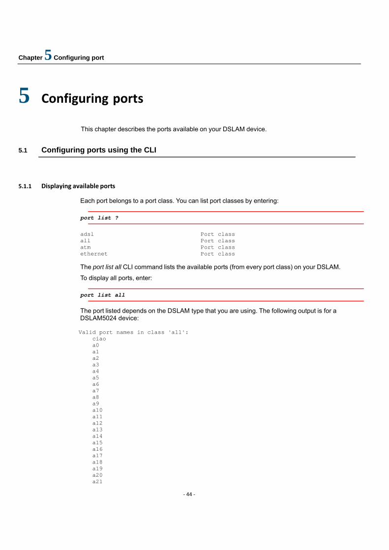
Each port belongs to a port class. You can list port classes by entering:
port list ?
adsl Port class all Port class atm Port class ethernet Port class The port list all CLI command lists the available ports (from every port class) on your DSLAM.
To display all ports, enter:
port list all
The port listed depends on the DSLAM type that you are using. The following output is for a DSLAM5024 device: Valid port names in class 'all': ciao a0 a1 a2 a3 a4 a5 a6 a7 a8 a9 a10 a11 a12 a13 a14 a15 a16 a17 a18 a19 a20 a21

Chapter 5 Configuring port
‐ 45 ‐
a22 a23 ethernet0
5.1.2 Displaying specific port information
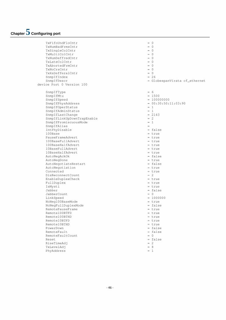
To view your Ethernet port settings, type the following CLI command:
port ethernet0 show Below is some example output:
Version = 1.00 PortClassEthernet = true FullDuplexEnable = true HashHigh = 0 HashLow = 0 Loopback = false MAC = 00:30:50:11:03:90 MaxMulticastListsize = 64 PadShortData = true PauseFrameEnable = true PhysicalPort = 0 PromiscuousEnable = true RxBroadcastEnable = true RxBufferOverflows = 0 RxDescBase = 0x21907160 RxDescCount = 10 RxMissedFrames = 0 RxMulticastAllEnable = true RxMulticastEnable = true RxNoBufAvailable = 0 RxNoPacketsDone = 0 RxPacketTooBig = 0 RxWatchdogTimeout = 0 RxNumFrmsAllCntr = 529 RxNumFrmsOkCntr = 529 RxCntrlFrmsCntr = 0 RxUnsupCntrlCntr = 0 RxNumBytsAllCntr = 55404 RxNumBytsOkCntr = 55404 RxUnicastCntr = 1 RxMulticastCntr = 528 RxBroadcastCntr = 36 RxFifoOvrFloCntr = 0 RxMinLenCntr = 0 RxMaxLenCntr = 0 RxCrcErrorCntr = 0 RxAlignErrorCntr = 0 RxLengthErrCntr = 0 RxEthrTypFrmCntr = 528 TxDescBase = 0x21907790 TxDescCount = 64 TxNoPacketsDone = 1 TxPacketTooBig = 0 TxNumFrmsAllCntr = 0 TxCntrlFrmsCntr = 0 TxNumBytsAllCntr = 0 TxNumBytsOkCntr = 0 TxUnicastCntr = 0 TxMulticastCntr = 0 TxBroadcastCntr = 0
Chapter 5 Configuring port
‐ 46 ‐
TxFifoUndFloCntr = 0 TxNumBadFrmsCntr = 0 TxSingleColCntr = 0 TxMultiColCntr = 0 TxNumDeffredCntr = 0 TxLateColCntr = 0 TxAbortedFrmCntr = 0 TxNoCrsCntr = 0 TxXsDefferalCntr = 0 SnmpIfIndex = 26 SnmpIfDescr = GlobespanVirata cf_ethernet
device Port 0 Version 100 SnmpIfType = 6 SnmpIfMtu = 1500 SnmpIfSpeed = 100000000 SnmpIfPhysAddress = 00:30:50:11:03:90 SnmpIfOperStatus = 1 SnmpIfAdminStatus = 1 SnmpIfLastChange = 2143 SnmpIfLinkUpDownTrapEnable = 2 SnmpIfPromiscuousMode = 1 SnmpIfAlias = IntPhyDisable = false 100Base = true PauseFrameAdvert = true 100BaseFullAdvert = true 100BaseHalfAdvert = true 10BaseFullAdvert = true 10BaseHalfAdvert = true AutoNegAckOk = false AutoNegDone = true AutoNegotiateRestart = false AutoNegotiation = true Connected = true DisReconnectCount = 2 EnableDuplexCheck = true FullDuplex = true IsMysti = true Jabber = false JabberCount = 0 LinkSpeed = 1000000 NoNeg100BaseMode = true NoNegFullDuplexMode = false RemotePauseFrame = true Remote100BTFD = true Remote100BTHD = true Remote10BTFD = true Remote10BTHD = true PowerDown = false RemoteFault = false RemoteFaultCount = 0 Reset = false RiseTimeAdj = 2 TxLevelAdj = 8 PhyAddress = 1

Chapter 5 Configuring port
‐ 47 ‐
5.1.3 Configuring a specific port
Some of the attributes displayed by the port ethernet show command can be configured from the CLI. To identify which attributes can be configured, enter:
port ethernet set ?
MAC
resetDefaults
To display the value options available for a specific attribute, enter the following:
port ethernet set <attribute> ?
For example:
port ethernet set resetDefaults ?
false
true
Enter the command with the required value, for example:
port ethernet0 set Reset true
Chapter 6 Configuring DSL
‐ 48 ‐
6 Configuring DSL
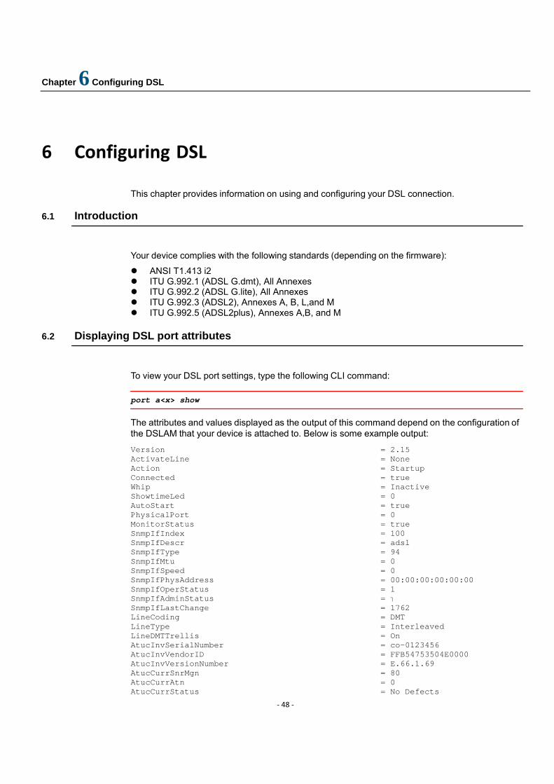
This chapter provides information on using and configuring your DSL connection. 6.1 Introduction
Your device complies with the following standards (depending on the firmware):
ANSI T1.413 i2 ITU G.992.1 (ADSL G.dmt), All Annexes ITU G.992.2 (ADSL G.lite), All Annexes ITU G.992.3 (ADSL2), Annexes A, B, L,and M ITU G.992.5 (ADSL2plus), Annexes A,B, and M
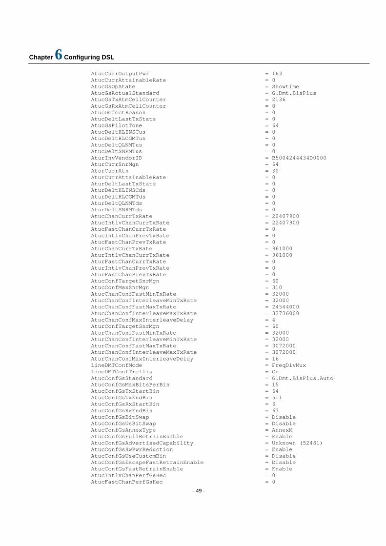
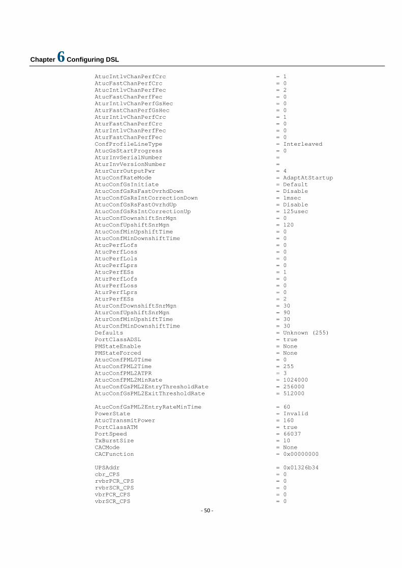
6.2 Displaying DSL port attributes
To view your DSL port settings, type the following CLI command:
port a<x> show
The attributes and values displayed as the output of this command depend on the configuration of the DSLAM that your device is attached to. Below is some example output:
Version = 2.15 ActivateLine = None Action = Startup Connected = true Whip = Inactive ShowtimeLed = 0 AutoStart = true PhysicalPort = 0 MonitorStatus = true SnmpIfIndex = 100 SnmpIfDescr = adsl SnmpIfType = 94 SnmpIfMtu = 0 SnmpIfSpeed = 0 SnmpIfPhysAddress = 00:00:00:00:00:00 SnmpIfOperStatus = 1
�SnmpIfAdminStatus = SnmpIfLastChange = 1762 LineCoding = DMT LineType = Interleaved LineDMTTrellis = On AtucInvSerialNumber = co-0123456 AtucInvVendorID = FFB54753504E0000 AtucInvVersionNumber = E.66.1.69 AtucCurrSnrMgn = 80 AtucCurrAtn = 0 AtucCurrStatus = No Defects
Chapter 6 Configuring DSL
‐ 49 ‐
AtucCurrOutputPwr = 163 AtucCurrAttainableRate = 0 AtucGsOpState = Showtime AtucGsActualStandard = G.Dmt.BisPlus AtucGsTxAtmCellCounter = 2136 AtucGsRxAtmCellCounter = 0 AtucDefectReason = 0 AtucDeltLastTxState = 0 AtucGsPilotTone = 64 AtucDeltHLINSCus = 0 AtucDeltHLOGMTus = 0 AtucDeltQLNMTus = 0 AtucDeltSNRMTus = 0 AturInvVendorID = B5004244434D0000 AturCurrSnrMgn = 64 AturCurrAtn = 30 AturCurrAttainableRate = 0 AturDeltLastTxState = 0 AturDeltHLINSCds = 0 AturDeltHLOGMTds = 0 AturDeltQLNMTds = 0 AturDeltSNRMTds = 0 AtucChanCurrTxRate = 22407900 AtucIntlvChanCurrTxRate = 22407900 AtucFastChanCurrTxRate = 0 AtucIntlvChanPrevTxRate = 0 AtucFastChanPrevTxRate = 0 AturChanCurrTxRate = 961000 AturIntlvChanCurrTxRate = 961000 AturFastChanCurrTxRate = 0 AturIntlvChanPrevTxRate = 0 AturFastChanPrevTxRate = 0 AtucConfTargetSnrMgn = 60 AtucConfMaxSnrMgn = 310 AtucChanConfFastMinTxRate = 32000 AtucChanConfInterleaveMinTxRate = 32000 AtucChanConfFastMaxTxRate = 24544000 AtucChanConfInterleaveMaxTxRate = 32736000 AtucChanConfMaxInterleaveDelay = 4 AturConfTargetSnrMgn = 60 AturChanConfFastMinTxRate = 32000 AturChanConfInterleaveMinTxRate = 32000 AturChanConfFastMaxTxRate = 3072000 AturChanConfInterleaveMaxTxRate = 3072000 AturChanConfMaxInterleaveDelay = 16 LineDMTConfMode = FreqDivMux LineDMTConfTrellis = On AtucConfGsStandard = G.Dmt.BisPlus.Auto AtucConfGsMaxBitsPerBin = 15 AtucConfGsTxStartBin = 64 AtucConfGsTxEndBin = 511 AtucConfGsRxStartBin = 6 AtucConfGsRxEndBin = 63 AtucConfGsBitSwap = Disable AtucConfGsUsBitSwap = Disable AtucConfGsAnnexType = AnnexM AtucConfGsFullRetrainEnable = Enable AtucConfGsAdvertisedCapability = Unknown (52481) AtucConfGsHwPwrReduction = Enable AtucConfGsUseCustomBin = Disable AtucConfGsEscapeFastRetrainEnable = Disable AtucConfGsFastRetrainEnable = Enable AtucIntlvChanPerfGsHec = 0 AtucFastChanPerfGsHec = 0
Chapter 6 Configuring DSL
‐ 50 ‐
AtucIntlvChanPerfCrc = 1 AtucFastChanPerfCrc = 0 AtucIntlvChanPerfFec = 2 AtucFastChanPerfFec = 0 AturIntlvChanPerfGsHec = 0 AturFastChanPerfGsHec = 0 AturIntlvChanPerfCrc = 1 AturFastChanPerfCrc = 0 AturIntlvChanPerfFec = 0 AturFastChanPerfFec = 0 ConfProfileLineType = Interleaved AtucGsStartProgress = 0 AturInvSerialNumber = AturInvVersionNumber = AturCurrOutputPwr = 4 AtucConfRateMode = AdaptAtStartup AtucConfGsInitiate = Default AtucConfGsRsFastOvrhdDown = Disable AtucConfGsRsIntCorrectionDown = 1msec AtucConfGsRsFastOvrhdUp = Disable AtucConfGsRsIntCorrectionUp = 125usec AtucConfDownshiftSnrMgn = 0 AtucConfUpshiftSnrMgn = 120 AtucConfMinUpshiftTime = 0 AtucConfMinDownshiftTime = 0 AtucPerfLofs = 0 AtucPerfLoss = 0 AtucPerfLols = 0 AtucPerfLprs = 0 AtucPerfESs = 1 AturPerfLofs = 0 AturPerfLoss = 0 AturPerfLprs = 0 AturPerfESs = 2 AturConfDownshiftSnrMgn = 30 AturConfUpshiftSnrMgn = 90 AturConfMinUpshiftTime = 30 AturConfMinDownshiftTime = 30 Defaults = Unknown (255) PortClassADSL = true PMStateEnable = None PMStateForced = None AtucConfPML0Time = 0 AtucConfPML2Time = 255 AtucConfPML2ATPR = 3 AtucConfPML2MinRate = 1024000 AtucConfGsPML2EntryThresholdRate = 256000 AtucConfGsPML2ExitThresholdRate = 512000 AtucConfGsPML2EntryRateMinTime = 60 PowerState = Invalid AtucTransmitPower = 160 PortClassATM = true PortSpeed = 66037 TxBurstSize = 10 CACMode = None CACFunction = 0x00000000 UPSAddr = 0x01326b34 cbr_CPS = 0 rvbrPCR_CPS = 0 rvbrSCR_CPS = 0 vbrPCR_CPS = 0 vbrSCR_CPS = 0

Chapter 6 Configuring DSL
‐ 51 ‐
ubr_CPS = 2000 ubrMCR_CPS = 0 RingLength = 1000 VPIRange = 12 VCIRange = 16 DefaultPCR = 2000 DefaultMaxQueue = 64 TrafficShaping = false NiType = nni HighSpeedRxPort = false HighSpeedTxPort = false HwVPBreakout = false .
6.3 Configuring DSL port attributes
You may want to modify various DSL parameters to ensure the correct operation of the device with your test equipment, or to prepare your devices for operation in a particular environment in which they will be deployed.
Some of the attributes displayed by the port a1 show command can be configured from the CLI. To identify which attributes can be configured, enter:
port a1 set ?
The attributes displayed as the output of this command depend on the configuration of the DSLAM and the capability of the Central Office (CO) that your device is attached to. Below is some example output:
Action ActivateLine AtucChanConfFasMaxTxRate AtucChanConfFastMinTxRate AtucChanConfInterleaveMaxTxRate AtucChanConfInterleaveMinTxRate AtucChanConfMaxInterleaveDelay AtucConfDownshiftSnrMgn AtucConfGsAnnexType AtucConfGsBitSwap AtucConfGsEscapeFastRetrainEnable AtucConfGsFastRetrainEnable AtucConfGsFullRetrainEnable AtucConfGsInitiate AtucConfGsMaxBitsPerBin AtucConfGsPML2EntryRateMinTime AtucConfGsPML2EntryThresholdRate AtucConfGsPML2ExitThresholdRate AtucConfGsRsFastOvrhdDown AtucConfGsRsFastOvrhdUp AtucConfGsRsIntCorrectionDown AtucConfGsRsIntCorrectionUp AtucConfGsRxEndBin AtucConfGsRxStartBin AtucConfGsStandard AtucConfGsTxEndBin AtucConfGsTxStartBin AtucConfGsUsBitSwap AtucConfGsUseCustomBin AtucConfMaxSnrMgn AtucConfMinDownshiftTime

Chapter 6 Configuring DSL
‐ 52 ‐
AtucConfMinUpshiftTime AtucConfPML0Time AtucConfPML2ATPR AtucConfPML2MinRate AtucConfPML2Time AtucConfRateMode AtucConfTargetSnrMgn AtucConfUpshiftSnrMgn AturChanConfFastMaxTxRate AturChanConfFastMinTxRate AturChanConfInterleaveMaxTxRae AturChanConfInterleaveMinTxRate AturChanConfMaxInterleaveDelay AturConfDownshiftSnrMgn AturConfMinDownshiftTime AturConfMinUpshiftTime AturConfTargetSnrMgn AturConfUpshiftSnrMgn AutoStart ConfProfileLineType Defaults LineDMTConfMode LineDMTConfTrellis MonitorStatus PMStateEnable PMStateForced Whip
To display the value options available for a specific attribute, enter the following:
port a1 set <attribute> ?
For example:
port a1 set ActivateLine ?
Abort
None
Start
Enter the command with the required value, for example:
port a1 set ActivateLine Start 6.4 Configuring the DSL standard
To change your preferred standard compliance, enter the command:
port <adsl port name> set AtucConfGsStandard <value>
with the <value> set to one of the following: T1.413 G.Lite G.DMT
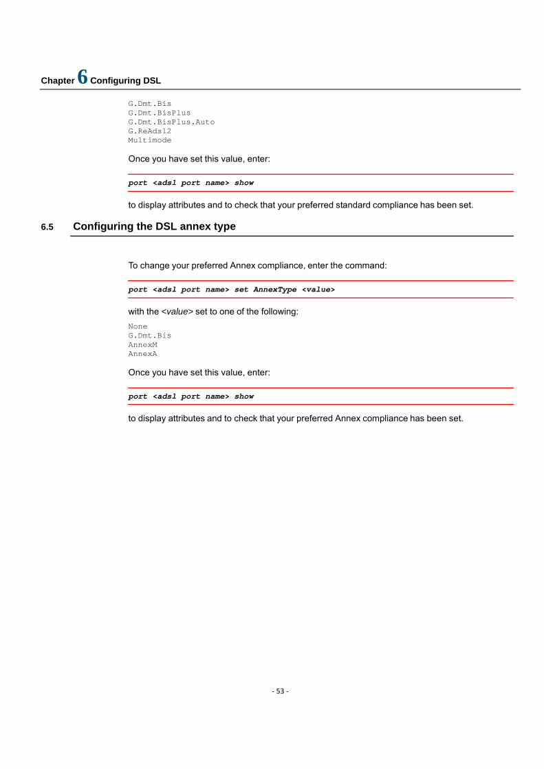
Chapter 6 Configuring DSL
‐ 53 ‐
G.Dmt.Bis G.Dmt.BisPlus G.Dmt.BisPlus.Auto G.ReAdsl2 Multimode Once you have set this value, enter:
port <adsl port name> show
to display attributes and to check that your preferred standard compliance has been set.
6.5 Configuring the DSL annex type
To change your preferred Annex compliance, enter the command:
port <adsl port name> set AnnexType <value>
with the <value> set to one of the following:
None G.Dmt.Bis AnnexM AnnexA Once you have set this value, enter:
port <adsl port name> show
to display attributes and to check that your preferred Annex compliance has been set.
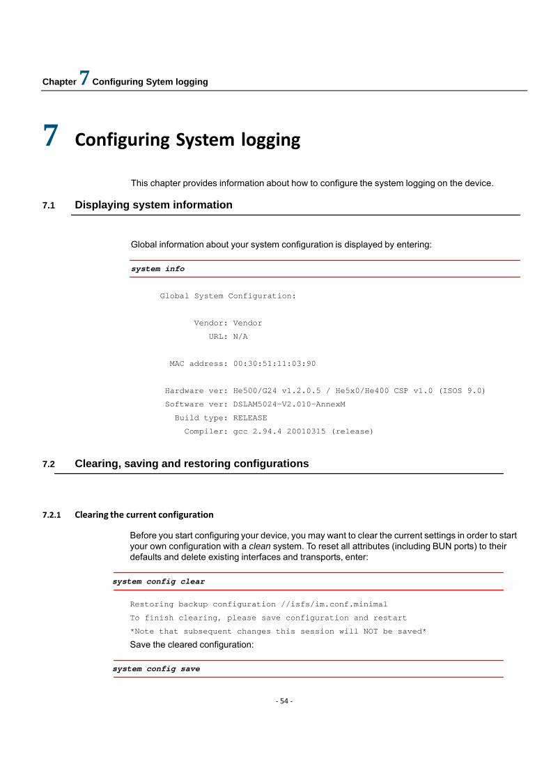
Chapter 7 Configuring Sytem logging
‐ 54 ‐
7 Configuring System logging
This chapter provides information about how to configure the system logging on the device. 7.1 Displaying system information
Global information about your system configuration is displayed by entering:
system info
Global System Configuration:
Vendor: Vendor
URL: N/A
MAC address: 00:30:51:11:03:90
Hardware ver: He500/G24 v1.2.0.5 / He5x0/He400 CSP v1.0 (ISOS 9.0)
Software ver: DSLAM5024-V2.010-AnnexM
Build type: RELEASE
Compiler: gcc 2.94.4 20010315 (release) 7.2 Clearing, saving and restoring configurations
7.2.1 Clearing the current configuration
Before you start configuring your device, you may want to clear the current settings in order to start your own configuration with a clean system. To reset all attributes (including BUN ports) to their defaults and delete existing interfaces and transports, enter:
system config clear
Restoring backup configuration //isfs/im.conf.minimal
To finish clearing, please save configuration and restart
*Note that subsequent changes this session will NOT be saved*
Save the cleared configuration:
system config save
Chapter 7 Configuring Sytem logging
‐ 55 ‐
7.2.2 Saving configuration changes
Whenever you change the device configuration and then enter the CLI command:
system config save
the changes are saved to the im.conf file in FlashFS. Enter the following:
system restart
7.2.3 Restoring a configuration
To restore the factory defaults configuration stored in the //isfs/im.conf.factory file, enter:
system config restore factory
To reset attributes to their defaults and delete all existing interfaces and transports, enter:
system config restore minimal
7.3 Updating system firmware
To update Flash memory (FlashFS) with the files contained in ISFS that are not yet present in FlashFS, enter the following commands:
console enable
Switching from CLI to console mode - type ‘exit’ to return
flashfs update
FlashFS effectively provides a backup of all the information contained in ISFS.

Chapter 8 Configuring RFC1483
‐ 56 ‐
8 Configuring RFC1483
This chapter provides information about the RFC 1483.
The RFC 1483 transport provides the simplest method of connecting end stations over an ATM network. RFC 1483 can either be used in bridged mode, where Ethernet packets are encapsulated in AAL-5 (ATM Adaptation Layer-5) PDUs (Protocol Data Units), or routed mode, where IP packets are encapsulated in AAL-5 PDUs.
It is most often used in bridged mode, which allows MAC-level Ethernet to be bridged directly to RFC 1483.
8.1 Ethernet - RFC1483 bridged
In this configuration, the DSLAM device uses the Bridge module to bridge between Ethernet and RFC 1483 at Layer 2. The systems do not need to be configured with any IP address information because both LAN PCs are on the same subnet. The RFC 1483 encapsulated frames run over a PVC .
Figure 8-1: Ethernet-RFC1483 bridged configuration
The outline configuration procedure is as follows:
1. Configure the PCs; 3. Configure the DSLAM;
Chapter 8 Configuring RFC1483
‐ 57 ‐
8.1.1 Configure PC A and PC B
The PCs will have IP addresses on the same subnet as the router’s LAN IP address (192.168.1.1 255.255.255.0). For example:
• PC A IP address: 192.168.1.2 Subnet mask: 255.255.255.0
• PC B (Wireless) IP address: 192.168.1.3 Subnet mask: 255.255.255.0
8.1.2 Configure the DSLAM
Clear your current configuration:
system config clear
system config save
system restart
Create an Ethernet transport and attach it to the bridge:
bridge add interface uplink
ethernet add transport ethernet0 ethernet0
bridge attach uplink ethernet0
Create an RFC1483 transport set to use Logical Link Control (LLC) encapsulation and attach it to the bridge:
rfc1483 add transport wb0 a0 0 101 llc bridged
rfc1483 add transport wb1 a1 0 101 llc bridged
bridge add interface wan0
bridge add interface wan1
bridge attach wan0 wb0

Chapter 8 Configuring RFC1483
‐ 58 ‐
bridge attach wan1 wb1
Chapter 9 Configuring User Accounts
‐ 59 ‐
9 Configuring User Accounts
This chapter provides information about how to manage the user accounts on your network. 9.1 Administering user accounts
By default, an administrator account exists with access privileges set to allow the administrator to create new accounts, save backup configurations, restore factory defaults and configure the device via the CLI, console and EmWeb. When the device first boots, you login to it using the default login name and password admin:
Login: admin
Password: *****
Login successful
Once logged in, the administrator can create and configure new accounts for additional users. 9.1.1 Adding new user accounts
There are two types of account that you can add to the system:
• a dialin account that allows the user to access the system via a dialin connection, for example, using PPP, but cannot login to the system directly.
• a login account that allows the user to login to the system directly, but cannot access the system via a dialin connection.
To add a dialin user, use the command:
system add user <name> [“comment”]
For example:
system add user fred “user with dialin access”
To add a login user, use the command:
system add login <name> [“comment”]
For example:
system add login joe “user with login access”
The default attributes for each dialin and login user account are as follows:
Table 9-1: Default user attributes
Default attributes Dialin user Login user

Chapter 9 Configuring User Accounts
‐ 60 ‐
User can dialin to the system via the CLI Yes No User can login to the system via the CLI No Yes User can access the web pages No Yes Default access permission set default user default user
.
NOTE: The term user is used throughout this chapter to refer to both login and dialin users, unless otherwise specified.
9.1.2 Configuring existing user accounts
By default, new users are given a default access level. There are three access level options for CLI users:
• default user - can configure the device using CLI commands; cannot enter usable console commands or blacklisted console commands
• engineer - can configure the device using CLI commands and usable console commands; cannot use blacklisted console commands
• super user - can configure the device using CLI commands, usable console commands and blacklisted console commands. Can also set up user login accounts, save backup configuration and restore factory settings.
s
To change the access level for an existing user, enter:
system set {login|user} <name> access {default|engineer|superuser}
To configure the dialin setting for an existing user, enter:
system set {login|user} <name> maydialin {enabled|disabled}
To allow/prevent access to the device via the CLI for an existing user, enter:
system set {login|user} <name> mayconfigure {enabled|disabled}
To allow/prevent access to the device via EmWeb for an existing user, enter:
system set {login|user} <name> mayconfigureweb {enabled|disabled}
To display information about users, enter one of the following commands:
system list users
system list logins
The output displayed for each command is identical:
Users:
Chapter 9 Configuring User Accounts
‐ 61 ‐
May May conf. May Access
ID | Name | Conf. | web | Dialin | Level | Comment
---|------|---------|----------|----------|-----------|-------------------------
1 | joe | ENABLED | ENABLED |disabled | default | user with login access
2 | fred | disabled| ENABLED | ENABLED | default | user with dialin access
3 | admin| ENABLED | ENABLED | disabled | superuser | Default admin user
--------------------------------------------------------------------------------
To delete an existing dialin account, enter:
system delete user <name>
To delete an existing login account, enter:
system delete login <name>
9.1.3 Configuring user logins and passwords
As an administrator, you may want to login to the device using another user’s login, for example, to check the configuration changes that a user has made or to change their password access for security reasons.
To login to the device as another user, by entering:
user change <name>
The <name> is the other user’s account login name. Whilst logged in as a different user, you inherit that user’s access permissions. For example, if the user account has default or engineer access permissions set, you will inherit these and lose your super user status. For more information about access permissions.
Once you have entered the user change command, you can set a new password on the account without having to enter the existing password. Enter:
user password
Enter the new password twice as prompted:
Enter new password: ******
Again to verify: ******
Alternatively, you can change a user’s password without having to enter the user change command by entering:
system set user <name> password <password>
Chapter 10 Configuring Snmp agent
‐ 62 ‐
10 Configuring Snmp agent This chapter provides information about how to setup snmp agent in system.
10.1 Snmp agent config
10.1.1 Display snmp config To view snmp agent config,type the following command:
snmp show config Below is the example output :
sysdescr: IP-DSLAM
sysobjectid:
syslocation: Shang_China
syscontact:
sysname: DSLAM5024
authentraps: disabled
snmpAutoSave: false
10.1.2 Configure snmp
To configure snmp ,enter
snmp set config <attribute> <value>
10.2 Snmp communitynames
10.2.1 Display snmp commnuitynames To view snmp communitynames ,type the following command:
snmp list communitynames Bellow is the example output:
-----------------------------------------------------------------------------
ID | Name | Community Name | Access| Manager |Temp|Perm
-----|----------|------------------------|-------|-----------------|----|----

Chapter 10 Configuring Snmp agent
‐ 63 ‐
1 | public | public | write | 0.0.0.0 | En | En
10.2.2 Create snmp commnuitynames
To create snmp communityname,type the following command:
snmp add communityname <name> <community> <read/write> <ip address> <enable/disable>
ip address and enable/disable is option parameters. For exmaple: To add a public community for snmp read .
snmp add communityname public public read
Chapter 11 Configuring with EmWeb
‐ 64 ‐
11 Configuring with EmWeb
This chapter describes how to configure the DSLAM using EmWeb,. EmWeb can be used as an alternative method for managing and administering your DSLAM.
11.1 References to CLI commands
Configuring your device using the Engineer web pages has the same effect as configuring it using the Command Line Interface (CLI). Throughout this chapter, you will see references to other chapters in this guide and CLI commands that provide functionality equivalent to EmWeb configurations.
11.2 Accessing EmWeb
At the console of one of your LAN PCs, type the following CLI command:
ip list interfaces
IP Interfaces:
ID | Name | IP Address | DHCP | Transport
-----|--------------|------------------|----------|----------------
1 | iplan | 192.168.1.32 | disabled | <BRIDGE>
-------------------------------------------------------------------
This command lists the interfaces available, including the LAN interface that is attached to your PC. The default LAN IP address is 192.168.1.32.
At your web browser, enter the LAN IP address as the URL 192.168.1.32 by default). The Status homepage for the Engineer web pages is displayed:
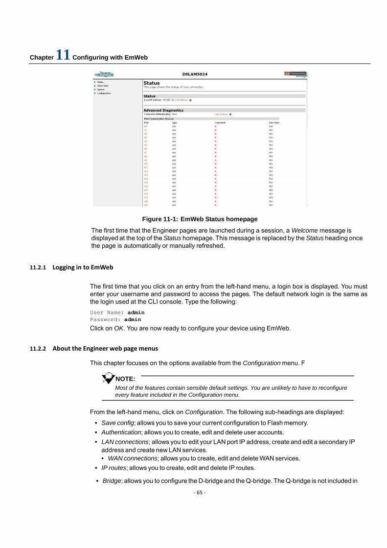
Chapter 11 Configuring with EmWeb
‐ 65 ‐
Figure 11-1: EmWeb Status homepage
The first time that the Engineer pages are launched during a session, a Welcome message is displayed at the top of the Status homepage. This message is replaced by the Status heading once the page is automatically or manually refreshed.
11.2.1 Logging in to EmWeb
The first time that you click on an entry from the left-hand menu, a login box is displayed. You must enter your username and password to access the pages. The default network login is the same as the login used at the CLI console. Type the following:
User Name: admin Password: admin
Click on OK. You are now ready to configure your device using EmWeb. 11.2.2 About the Engineer web page menus
This chapter focuses on the options available from the Configuration menu. F
NOTE: Most of the features contain sensible default settings. You are unlikely to have to reconfigure every feature included in the Configuration menu.
From the left-hand menu, click on Configuration. The following sub-headings are displayed:
• Save config; allows you to save your current configuration to Flash memory. • Authentication; allows you to create, edit and delete user accounts. • LAN connections; allows you to edit your LAN port IP address, create and edit a secondary IP
address and create new LAN services. • WAN connections; allows you to create, edit and delete WAN services.
• IP routes; allows you to create, edit and delete IP routes.
• Bridge; allows you to configure the D-bridge and the Q-bridge. The Q-bridge is not included in
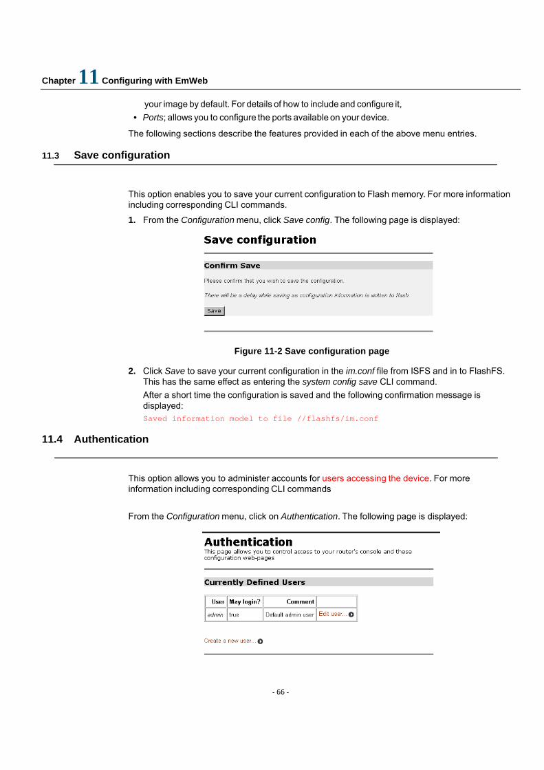
Chapter 11 Configuring with EmWeb
‐ 66 ‐
your image by default. For details of how to include and configure it, • Ports; allows you to configure the ports available on your device.
The following sections describe the features provided in each of the above menu entries.
11.3 Save configuration
This option enables you to save your current configuration to Flash memory. For more information including corresponding CLI commands.
1. From the Configuration menu, click Save config. The following page is displayed:
Figure 11-2 Save configuration page
2. Click Save to save your current configuration in the im.conf file from ISFS and in to FlashFS. This has the same effect as entering the system config save CLI command. After a short time the configuration is saved and the following confirmation message is displayed: Saved information model to file //flashfs/im.conf
11.4 Authentication
This option allows you to administer accounts for users accessing the device. For more information including corresponding CLI commands
From the Configuration menu, click on Authentication. The following page is displayed:
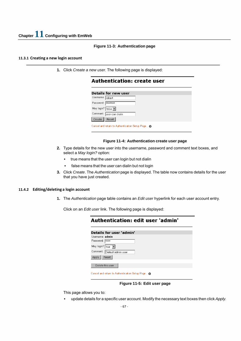
Chapter 11 Configuring with EmWeb
‐ 67 ‐
Figure 11-3: Authentication page
11.3.1 Creating a new login account
1. Click Create a new user. The following page is displayed:
Figure 11-4: Authentication create user page
2. Type details for the new user into the username, password and comment text boxes, and select a May login? option: • true means that the user can login but not dialin
• false means that the user can dialin but not login 3. Click Create. The Authentication page is displayed. The table now contains details for the user
that you have just created. 11.4.2 Editing/deleting a login account
1. The Authentication page table contains an Edit user hyperlink for each user account entry.
Click on an Edit user link. The following page is displayed:
Figure 11-5: Edit user page
This page allows you to: • update details for a specific user account. Modify the necessary text boxes then click Apply.
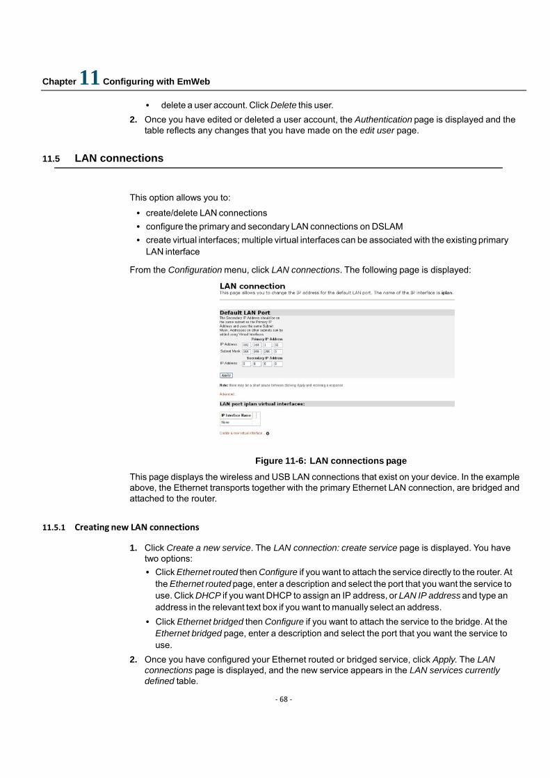
Chapter 11 Configuring with EmWeb
‐ 68 ‐
• delete a user account. Click Delete this user. 2. Once you have edited or deleted a user account, the Authentication page is displayed and the
table reflects any changes that you have made on the edit user page.
11.5 LAN connections
This option allows you to:
• create/delete LAN connections • configure the primary and secondary LAN connections on DSLAM • create virtual interfaces; multiple virtual interfaces can be associated with the existing primary
LAN interface
From the Configuration menu, click LAN connections. The following page is displayed:
Figure 11-6: LAN connections page
This page displays the wireless and USB LAN connections that exist on your device. In the example above, the Ethernet transports together with the primary Ethernet LAN connection, are bridged and attached to the router.
11.5.1 Creating new LAN connections
1. Click Create a new service. The LAN connection: create service page is displayed. You have two options: • Click Ethernet routed then Configure if you want to attach the service directly to the router. At
the Ethernet routed page, enter a description and select the port that you want the service to use. Click DHCP if you want DHCP to assign an IP address, or LAN IP address and type an address in the relevant text box if you want to manually select an address.
• Click Ethernet bridged then Configure if you want to attach the service to the bridge. At the Ethernet bridged page, enter a description and select the port that you want the service to use.
2. Once you have configured your Ethernet routed or bridged service, click Apply. The LAN connections page is displayed, and the new service appears in the LAN services currently defined table.
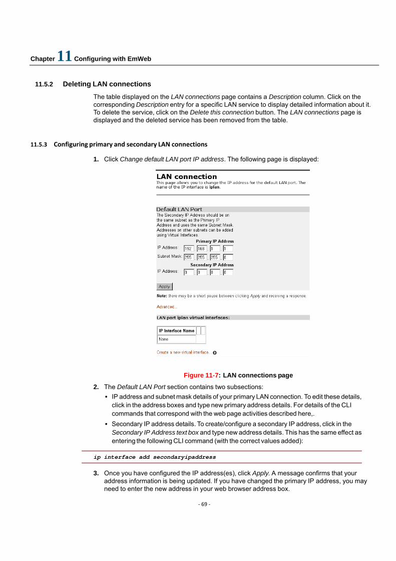
Chapter 11 Configuring with EmWeb
‐ 69 ‐
11.5.2 Deleting LAN connections
The table displayed on the LAN connections page contains a Description column. Click on the corresponding Description entry for a specific LAN service to display detailed information about it. To delete the service, click on the Delete this connection button. The LAN connections page is displayed and the deleted service has been removed from the table.
11.5.3 Configuring primary and secondary LAN connections
1. Click Change default LAN port IP address. The following page is displayed:
Figure 11-7: LAN connections page
2. The Default LAN Port section contains two subsections: • IP address and subnet mask details of your primary LAN connection. To edit these details,
click in the address boxes and type new primary address details. For details of the CLI commands that correspond with the web page activities described here,.
• Secondary IP address details. To create/configure a secondary IP address, click in the Secondary IP Address text box and type new address details. This has the same effect as entering the following CLI command (with the correct values added):
ip interface add secondaryipaddress
3. Once you have configured the IP address(es), click Apply. A message confirms that your
address information is being updated. If you have changed the primary IP address, you may need to enter the new address in your web browser address box.
Chapter 11 Configuring with EmWeb
‐ 70 ‐
4. To carry out further configuration of your LAN interface, click Advanced. The page displayed features tabs across the top. Clicking on a tab displays advanced information about the interface. You can modify the values displayed on each page, then click Change to save changes. The tabs and their values are as follows:
Table 11-1: Advanced LAN configuration features
Tab heading Configuration options Corresponding CLI commands Change the IP address and netmask ip set interface ipaddress
ip set interface netmask Set the Maximum Transmission Unit ip set interface mtu
Edit ‘Ip Interface’ Attach the LAN interface to a real interface, making it a virtual interface.
ip attachvirtual
Edit Tcp Mss Clamp Sets the TCP Maximum Segment Size Clamp functionality (true or false).
ip set interface tcpmssclamp
Edit Rip Versions
Set which RIP versions can be accepted by or sent from the interface, and whether multicast packets can be sent.
ip set interface rip accept ip set interface rip send ip set interface rip multicast
Edit NAT
Enable/disable NAT between the LAN interface and the external (WAN) interface.
nat enable
11.5.4 Creating virtual interfaces
1. From the Configuration menu, click LAN connections. Click Change Default LAN port IP address. At the bottom of the page, click Create a new virtual interface.
2. At the Create virtual interface page, type the IP address and netmask of the virtual interface, then click Apply.
3. The LAN connections page is displayed. The virtual interfaces section contains a table listing the names of the virtual interface(s). Each virtual interface is called item# by default.
4. Each virtual interface name has an Edit and a Delete link associated with it. To edit a service: • Click Edit. Change the options for the existing virtual interface, then click Change. The page
is reset and the new values are displayed. To delete a service: • Click Delete. Check the details displayed, then click Delete this connection.
For further information including details of the CLI commands that correspond with the web page activities described here.
11.6 WAN connections
This option allows you to create and configure WAN connections for your device. You can also create virtual interfaces on routed services. From the Configuration menu, click on WAN connections. The WAN connections page is displayed:
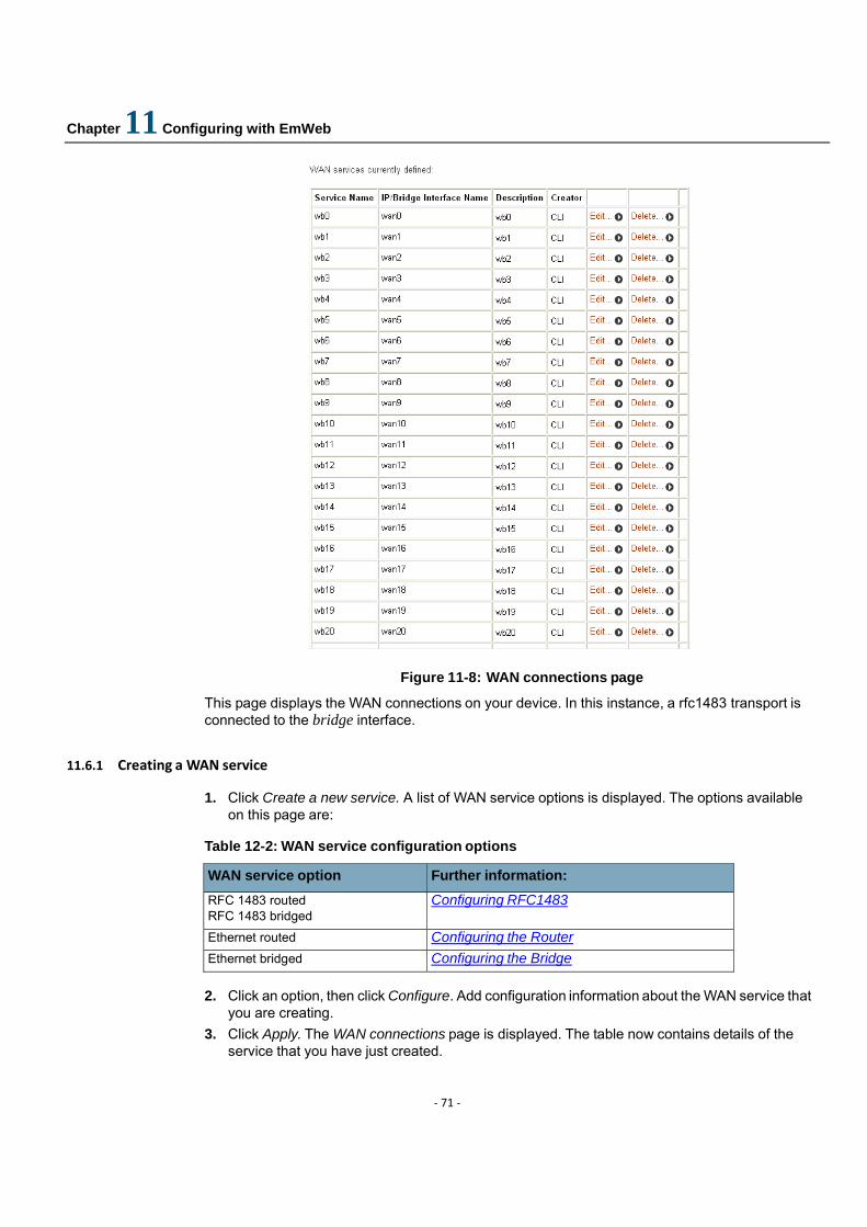
Chapter 11 Configuring with EmWeb
‐ 71 ‐
Figure 11-8: WAN connections page
This page displays the WAN connections on your device. In this instance, a rfc1483 transport is connected to the bridge interface.
11.6.1 Creating a WAN service
1. Click Create a new service. A list of WAN service options is displayed. The options available on this page are:
Table 12-2: WAN service configuration options
WAN service option Further information: RFC 1483 routed RFC 1483 bridged
Configuring RFC1483
Ethernet routed Configuring the Router Ethernet bridged Configuring the Bridge
2. Click an option, then click Configure. Add configuration information about the WAN service that
you are creating. 3. Click Apply. The WAN connections page is displayed. The table now contains details of the
service that you have just created.
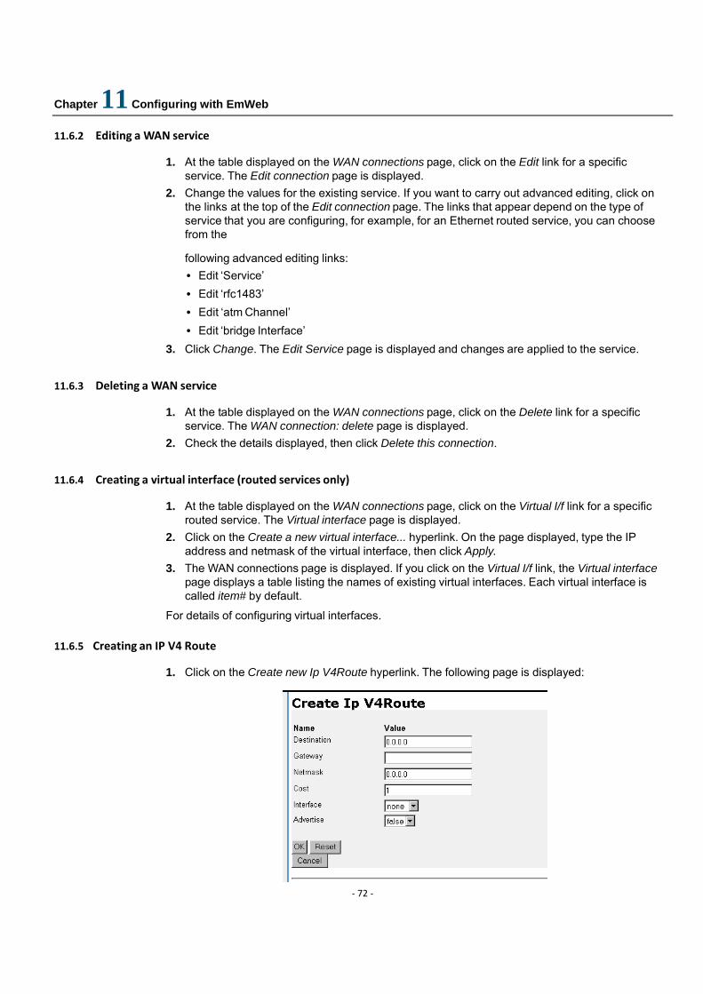
Chapter 11 Configuring with EmWeb
‐ 72 ‐
11.6.2 Editing a WAN service
1. At the table displayed on the WAN connections page, click on the Edit link for a specific service. The Edit connection page is displayed.
2. Change the values for the existing service. If you want to carry out advanced editing, click on the links at the top of the Edit connection page. The links that appear depend on the type of service that you are configuring, for example, for an Ethernet routed service, you can choose from the
following advanced editing links: • Edit ‘Service’ • Edit ‘rfc1483’ • Edit ‘atm Channel’ • Edit ‘bridge Interface’
3. Click Change. The Edit Service page is displayed and changes are applied to the service. 11.6.3 Deleting a WAN service
1. At the table displayed on the WAN connections page, click on the Delete link for a specific service. The WAN connection: delete page is displayed.
2. Check the details displayed, then click Delete this connection. 11.6.4 Creating a virtual interface (routed services only)
1. At the table displayed on the WAN connections page, click on the Virtual I/f link for a specific routed service. The Virtual interface page is displayed.
2. Click on the Create a new virtual interface... hyperlink. On the page displayed, type the IP address and netmask of the virtual interface, then click Apply.
3. The WAN connections page is displayed. If you click on the Virtual I/f link, the Virtual interface page displays a table listing the names of existing virtual interfaces. Each virtual interface is called item# by default.
For details of configuring virtual interfaces.
11.6.5 Creating an IP V4 Route
1. Click on the Create new Ip V4Route hyperlink. The following page is displayed:

Chapter 11 Configuring with EmWeb
‐ 73 ‐
Figure 11-9:Create IP V4 Route page
2. Complete the Create IP v4 Route form: • Specify a Destination network (or single host), together with a Netmask to indicate what
range of addresses the network covers • Specify a next-hop Gateway address or interface • Specify the number of hops counted as the Cost of the route • Set the Interface used by the route (select none if you want it to route to any address via the
gateway) • Enable/disable the advertising of the route via RIP by selecting true/false. If there is a choice
of routes for a destination, the route with the most specific mask is chosen. Adding a route has the same effect as entering the ip add route CLI command.. The other attributes can be set using the CLI commands listed below.
ip set route destination
ip set route cost
ip set route gateway
ip set route interface
ip set route advertise
3. Click OK. The Edit Routes page is displayed:
Figure 11-10:Edit Routes page
The table contains details of the route that you have just created, including whether the route is valid or invalid .
11.6.6 Editing a route
At the Edit Routes page:
1. Change the destination, gateway, netmask or RIP advertise status of a route by clicking in the relevant text box, updating the information then click Apply.

Chapter 11 Configuring with EmWeb
‐ 74 ‐
2. To edit every attribute of the route including the interface and cost setting, click on the Advanced Options hyperlink for a specific route and update the relevant information. Click OK.
11.6.7 Deleting a route
At the Edit Routes page:
1. To delete an existing route, check the Delete? box associated with a specific route. 2. Click Apply.
11.7 Bridge
For more information on D-bridge and Q-bridge including details of the CLI commands that correspond with the web page activities described here. This option allows you to configure the D-bridge (802.1D) and the Q-bridge (802.1Q). The configuration described in this section assumes that you have included the Q-bridge option in your system file. If you are using the D-bridge without the Q-bridge, you can still access the Bridge Main Page, the Interface Configuration page and the Interface Statistics/Flushing page, but these pages will display a subset of the features/parameters shown as examples in this section.
The Bridge option allows you to:
• Modify or delete a bridge interface • Create, modify, or delete a VLAN • Set the following features of a VLAN:
• Tagged and untagged port list • Source and destination MAC-based unicast filtering • Multicast filtering • Forward all ports and unregistered ports.
• Display and clear statistical information
Figure 11-11:Bridge (Q-bridge mode) main page
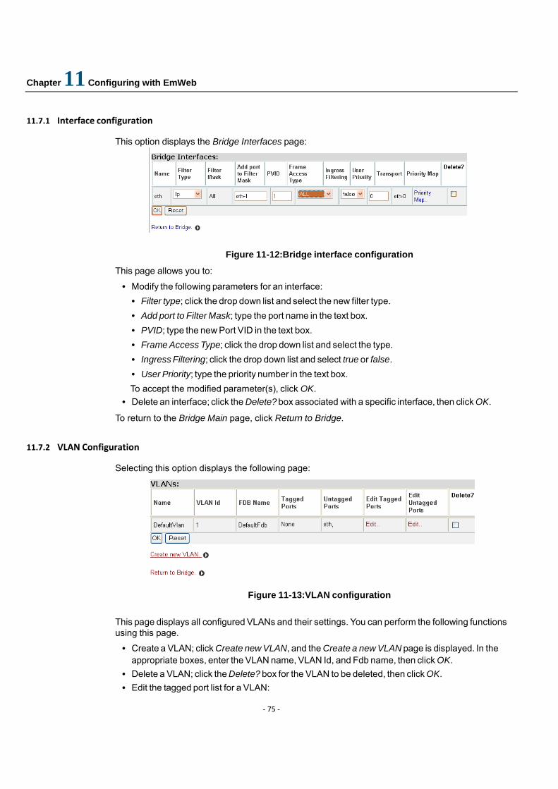
Chapter 11 Configuring with EmWeb
‐ 75 ‐
11.7.1 Interface configuration
This option displays the Bridge Interfaces page:
Figure 11-12:Bridge interface configuration
This page allows you to:
• Modify the following parameters for an interface: • Filter type; click the drop down list and select the new filter type. • Add port to Filter Mask; type the port name in the text box. • PVID; type the new Port VID in the text box. • Frame Access Type; click the drop down list and select the type. • Ingress Filtering; click the drop down list and select true or false. • User Priority; type the priority number in the text box. To accept the modified parameter(s), click OK.
• Delete an interface; click the Delete? box associated with a specific interface, then click OK.
To return to the Bridge Main page, click Return to Bridge. 11.7.2 VLAN Configuration
Selecting this option displays the following page:
Figure 11-13:VLAN configuration
This page displays all configured VLANs and their settings. You can perform the following functions using this page.
• Create a VLAN; click Create new VLAN, and the Create a new VLAN page is displayed. In the appropriate boxes, enter the VLAN name, VLAN Id, and Fdb name, then click OK.
• Delete a VLAN; click the Delete? box for the VLAN to be deleted, then click OK. • Edit the tagged port list for a VLAN:
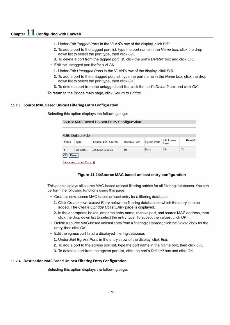
Chapter 11 Configuring with EmWeb
‐ 76 ‐
1. Under Edit Tagged Ports in the VLAN’s row of the display, click Edit. 2. To add a port to the tagged port list, type the port name in the Name box, click the drop
down list to select the port type, then click OK. 3. To delete a port from the tagged port list, click the port’s Delete? box and click OK.
• Edit the untagged port list for a VLAN: 1. Under Edit Untagged Ports in the VLAN’s row of the display, click Edit. 2. To add a port to the untagged port list, type the port name in the Name box, click the drop
down list to select the port type, then click OK. 3. To delete a port from the untagged port list, click the port’s Delete? box and click OK.
To return to the Bridge main page, click Return to Bridge.
11.7.3 Source MAC Based Unicast Filtering Entry Configuration
Selecting this option displays the following page:
Figure 11-14:Source MAC based unicast entry configuration
This page displays all source MAC-based unicast filtering entries for all filtering databases. You can perform the following functions using this page.
• Create a new source MAC-based unicast entry for a filtering database: 1. Click Create new Unicast Entry below the filtering database to which the entry is to be
added. The Create Qbridge Ucast Entry page is displayed. 2. In the appropriate boxes, enter the entry name, receive port, and source MAC address, then
click the drop down list to select the entry type. To accept the values, click OK. • Delete a source MAC-based unicast entry from a filtering database; click the Delete? box for the
entry, then click OK. • Edit the egress port list of a displayed filtering database:
1. Under Edit Egress Ports in the entry’s row of the display, click Edit. 2. To add a port to the egress port list, type the port name in the Name box, then click OK. 3. To delete a port from the egress port list, click the port’s Delete? box and click OK.
11.7.4 Destination MAC Based Unicast Filtering Entry Configuration
Selecting this option displays the following page:
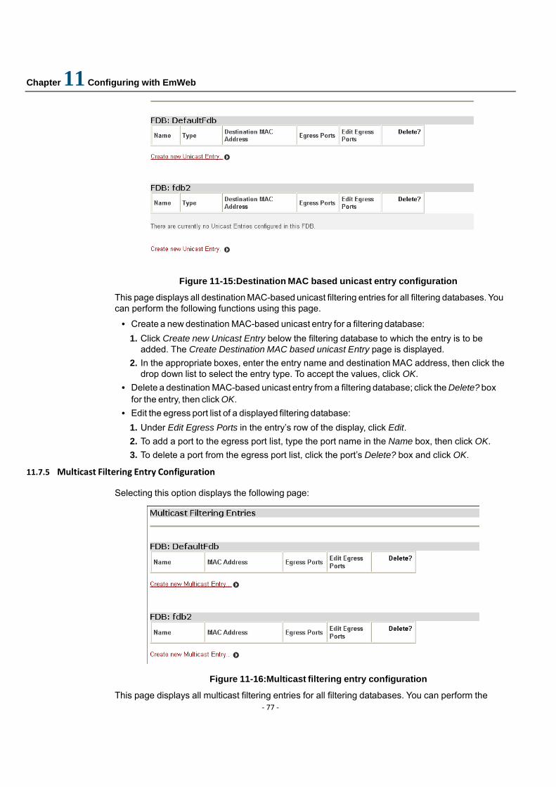
Chapter 11 Configuring with EmWeb
‐ 77 ‐
Figure 11-15:Destination MAC based unicast entry configuration
This page displays all destination MAC-based unicast filtering entries for all filtering databases. You can perform the following functions using this page.
• Create a new destination MAC-based unicast entry for a filtering database: 1. Click Create new Unicast Entry below the filtering database to which the entry is to be
added. The Create Destination MAC based unicast Entry page is displayed. 2. In the appropriate boxes, enter the entry name and destination MAC address, then click the
drop down list to select the entry type. To accept the values, click OK. • Delete a destination MAC-based unicast entry from a filtering database; click the Delete? box
for the entry, then click OK. • Edit the egress port list of a displayed filtering database:
1. Under Edit Egress Ports in the entry’s row of the display, click Edit. 2. To add a port to the egress port list, type the port name in the Name box, then click OK. 3. To delete a port from the egress port list, click the port’s Delete? box and click OK.
11.7.5 Multicast Filtering Entry Configuration
Selecting this option displays the following page:
Figure 11-16:Multicast filtering entry configuration
This page displays all multicast filtering entries for all filtering databases. You can perform the
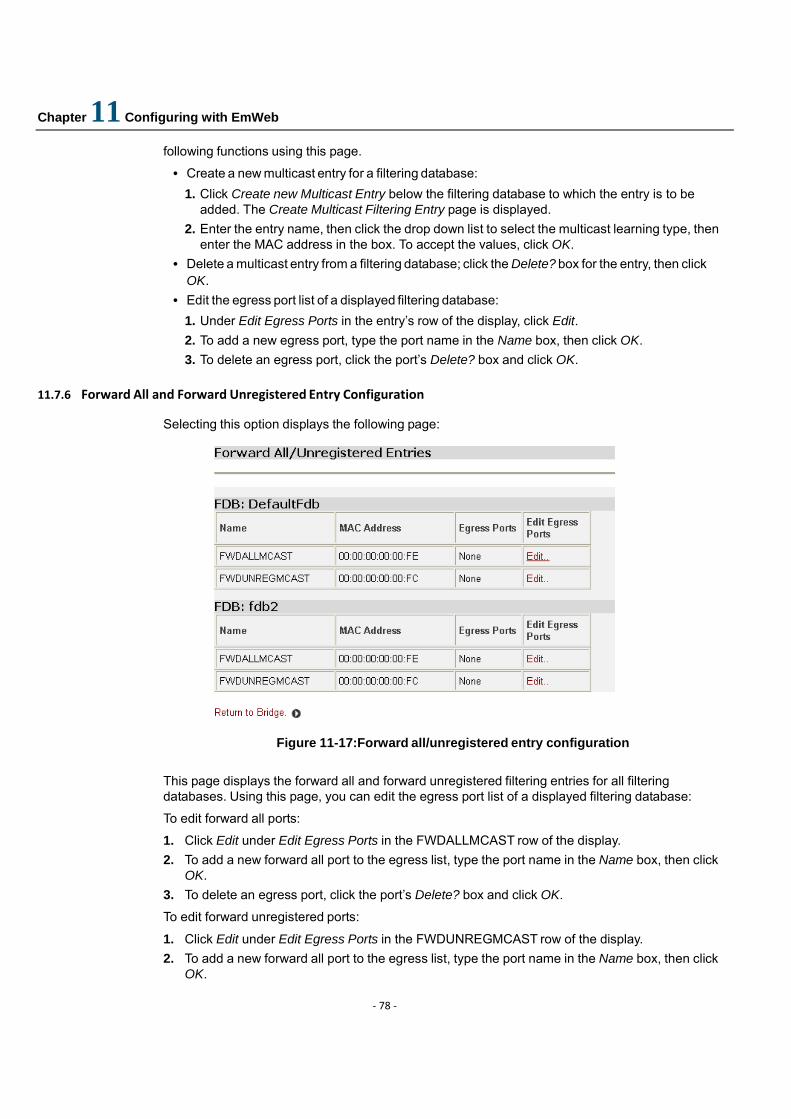
Chapter 11 Configuring with EmWeb
‐ 78 ‐
following functions using this page.
• Create a new multicast entry for a filtering database: 1. Click Create new Multicast Entry below the filtering database to which the entry is to be
added. The Create Multicast Filtering Entry page is displayed. 2. Enter the entry name, then click the drop down list to select the multicast learning type, then
enter the MAC address in the box. To accept the values, click OK. • Delete a multicast entry from a filtering database; click the Delete? box for the entry, then click
OK. • Edit the egress port list of a displayed filtering database:
1. Under Edit Egress Ports in the entry’s row of the display, click Edit. 2. To add a new egress port, type the port name in the Name box, then click OK. 3. To delete an egress port, click the port’s Delete? box and click OK.
11.7.6 Forward All and Forward Unregistered Entry Configuration
Selecting this option displays the following page:
Figure 11-17:Forward all/unregistered entry configuration
This page displays the forward all and forward unregistered filtering entries for all filtering databases. Using this page, you can edit the egress port list of a displayed filtering database:
To edit forward all ports:
1. Click Edit under Edit Egress Ports in the FWDALLMCAST row of the display. 2. To add a new forward all port to the egress list, type the port name in the Name box, then click
OK. 3. To delete an egress port, click the port’s Delete? box and click OK.
To edit forward unregistered ports:
1. Click Edit under Edit Egress Ports in the FWDUNREGMCAST row of the display. 2. To add a new forward all port to the egress list, type the port name in the Name box, then click
OK.
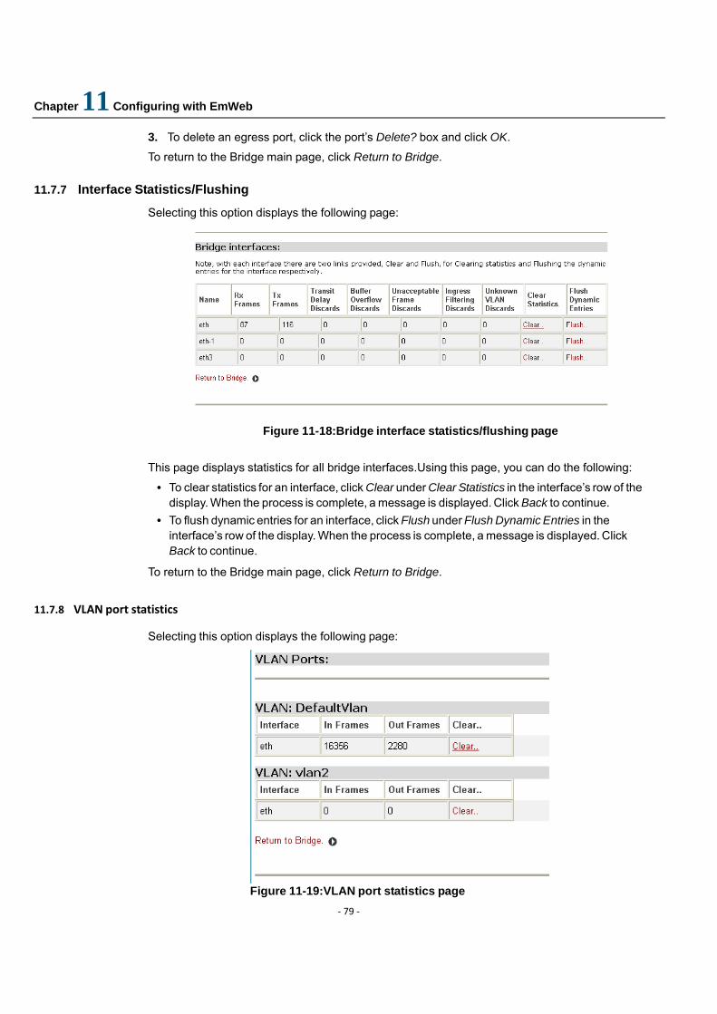
Chapter 11 Configuring with EmWeb
‐ 79 ‐
3. To delete an egress port, click the port’s Delete? box and click OK.
To return to the Bridge main page, click Return to Bridge. 11.7.7 Interface Statistics/Flushing
Selecting this option displays the following page:
Figure 11-18:Bridge interface statistics/flushing page
This page displays statistics for all bridge interfaces.Using this page, you can do the following:
• To clear statistics for an interface, click Clear under Clear Statistics in the interface’s row of the display. When the process is complete, a message is displayed. Click Back to continue.
• To flush dynamic entries for an interface, click Flush under Flush Dynamic Entries in the interface’s row of the display. When the process is complete, a message is displayed. Click Back to continue.
To return to the Bridge main page, click Return to Bridge. 11.7.8 VLAN port statistics
Selecting this option displays the following page:
Figure 11-19:VLAN port statistics page
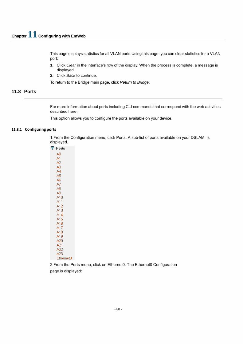
Chapter 11 Configuring with EmWeb
‐ 80 ‐
This page displays statistics for all VLAN ports.Using this page, you can clear statistics for a VLAN port:
1. Click Clear in the interface’s row of the display. When the process is complete, a message is displayed.
2. Click Back to continue.
To return to the Bridge main page, click Return to Bridge. 11.8 Ports
For more information about ports including CLI commands that correspond with the web activities described here,.
This option allows you to configure the ports available on your device.
11.8.1 Configuring ports
1.From the Configuration menu, click Ports. A sub-list of ports available on your DSLAM is displayed. 2.From the Ports menu, click on Ethernet0. The Ethernet0 Configuration page is displayed:
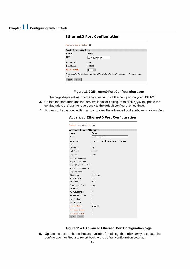
Chapter 11 Configuring with EmWeb
‐ 81 ‐
Figure 11-20:Ethernet0 Port Configuration page
The page displays basic port attributes for the Ethernet0 port on your DSLAM. 3. Update the port attributes that are available for editing, then click Apply to update the
configuration, or Reset to revert back to the default configuration settings. 4. To carry out advanced editing and/or to view the advanced port attributes, click on View
Figure 11-21:Advanced Ethernet0 Port Configuration page
5. Update the port attributes that are available for editing, then click Apply to update the configuration, or Reset to revert back to the default configuration settings.
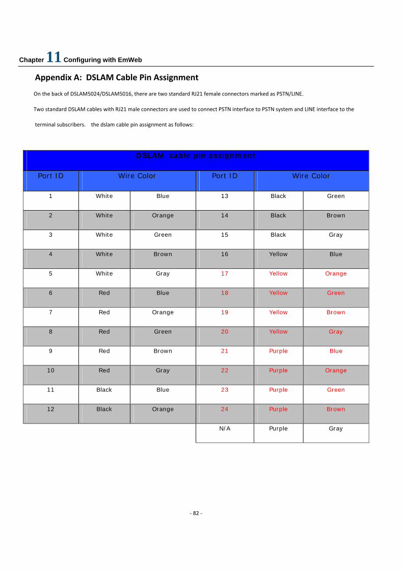
Chapter 11 Configuring with EmWeb
‐ 82 ‐
Appendix A: DSLAM Cable Pin Assignment
On the back of DSLAM5024/DSLAM5016, there are two standard RJ21 female connectors marked as PSTN/LINE.
Two standard DSLAM cables with RJ21 male connectors are used to connect PSTN interface to PSTN system and LINE interface to the
terminal subscribers. the dslam cable pin assignment as follows:
DSLAM cable pin assignment
Port ID Wire Color Port ID Wire Color
1 White Blue 13 Black Green
2 White Orange 14 Black Brown
3 White Green 15 Black Gray
4 White Brown 16 Yellow Blue
5 White Gray 17 Yellow Orange
6 Red Blue 18 Yellow Green
7 Red Orange 19 Yellow Brown
8 Red Green 20 Yellow Gray
9 Red Brown 21 Purple Blue
10 Red Gray 22 Purple Orange
11 Black Blue 23 Purple Green
12 Black Orange 24 Purple Brown
N/A Purple Gray