Embed Size (px)
Citation preview

2000 clamp
p. 1/12www.burkert.com
2/2-way Angle-Seat Valve for medium up to +180 °C, DN 15-50
The externally piloted angle-seat valve is
operated with a single or double-acting pis-
ton actuator. The actuator is available in two
different materials, PA and PPS depending
on the ambient temperature. The reliable self-
adjusting packing gland provides high sealing
integrity. High fl ow rates are attained with the
stainless steel 2-way body.
These maintenance-free and robust valves
can be retrofi tted with a comprehensive range
of accessories for position indication, stroke
limitation or manual override.
For valves with port connection threaded port
and weld end please see separate datasheets.
Type 2000 can be combined with…
• High flow rates
• Very high cycle life
• Clamp body according to EN ISO 2852,
BS 4825 or ASME BPE
• Deliverable with flow direction below or above seat
• Simple conversion of the circuit function
Technical data
Orifice DN15 to 50
Body materials Stainless steel 316L
Actuator material PA (PPS on request)
Seal material PTFE (NBR, FKM, EPDM on request)
Medium Water, alcohol, oils, fuel, hydraulic fl uids, salt solution,
alkali solutions, organic solvents, steam
Viscosity Max. 600 mm2/s
Packing gland
(with silicone grease)
PTFE V-rings with spring compensation
Medium temperature1) -10 to +180 ºC with PTFE seal
Ambient temperature
PA actuator1)
PPS actuator1) Ø 50-80
PPS actuator1) Ø 100-125
-10 to +60 ºC
+5 to +140 ºC
+5 to +90 ºC
Installation As required, preferably with actuator in upright position
Control medium Neutral gases, air
Max. pilot pressure
Actuator size Ø 50-80
Actuator size Ø 100
Actuator size Ø 100
Actuator size Ø 125
PA and PPS 10 bar
PA 10 bar
PPS 7 bar
PA and PPS 7 bar
Port connection acc.
on request
EN ISO 2852, BS 4825, ASME BPE
DIN 32676
Surface fi nish
on request
Standard Ra, internal ≤ 3.2 μm
Int. Ra ≤ 0.8 μm (external cast surface) electropolished
Int. Ra ≤ 0.4 μm (external cast surface) electropolished
1) Note: For PA actuators in the sizes 50 and 63, the com-
bination of max. medium temperature and max. ambient
temperature is as shown in the following chart
Ø 50 Ø 63
Am
bie
nt
tem
pera
ture
°C
Medium temperature °C
Type 8691
Control head
Type 8690
Pneum. control unit
with feedback
Type 1062
Electrical position
feedback
Type 8640/8644
Valve block
Type 6012/6014 P
Pilot valve
Valve specifi cations System spec. On/Off Classic Request for quotation
Type 2000 clamp Type 8801-YA/ 8803-YA
Type 8801-YA/8803-YA
Technical data & ordering info. p. 1-6 Ordering info. & technical data p. 7-10 p. 11
Content

2000 clamp
p. 2/12
Materials Type 2000 clamp
1
2
3
4
7
5
6
7
8
9
10
11
12
13
14
1 Transparent cap PC (with PPS actuator; PSU)
2 Pilot air ports Stainless steel 1.4305
3 Actuator PA (PPS on request)
4 Piston seal NBR (with PPS actuator; FKM)
5 Spring Stainless steel 1.4310
6 Tube Stainless steel 1.4401
7 V-Seals PTFE (FKM on request)
8 Wiper PTFE
9 Nipple Stainless steel 1.4401
10 Spindle Stainless steel 1.4401
11 Pins Stainless steel 1.4401
12 Swivel plate Stainless steel 1.4401
13 Seal PTFE (NBR, FKM, EPDM on request)
14 Valve body Stainless steel 316L

2000 clamp
p. 3/12
Technical data for Type 2000 clamp with flow direction below seat (for gas and liquid)
Flow direction below seat
Orifi ce Actuator
size
Kv value
water
Min. pilot
pressure
Max. operating
pressure up to +180º
Weight
[mm] [mm] (m3/h) CFA [bar] CFA [bar] CFB [bar] [kg]
15 50 4.2 3.9 16 16 0.8
20 50 8.0 3.9 11 16 1.0
25 50 14.5 – – 16 1.2
63 19 4.2 11 16 1.8
32 63 27 4.2 6 16 2.3
80 28 5.0 14 16 3.1
40 63 35 – – 16 2.7
80 38 5.0 9 16 3.5
50 63 49 – – 13 4.0
100 55 4.4 7.2 – 7.0
Diagram 1 Diagram 2
Pilot pressure diagram with control function B and flow direction below seat
Ordering chart for valves with flow direction below seat (further versions on request)
Valves with clamp connection acc. to ISO 2852, ASME BPE or BS 4825, body in stainless steel,
actuator material PA, Ra internal ≤ 3.2 μm
Co
ntr
ol
fun
cti
on
Ori
fi ce
[mm
]
Actu
ato
r siz
e
ø [
mm
]
Port connection Clamp
external Ø [mm]
Min
.p
ilo
t p
ressu
re[b
ar]
Op
era
tin
g
pre
ssu
reu
p t
o 1
80 º
C
[ba
r]
Item no.
ISO
2852
AS
ME
B
PE
BS
4825
ISO
2852
AS
ME
B
PE
BS
4825
A 15 50 34.0 25.0 25.0 3.9 16 415 070 175 574 183 245
20 50 50.5 25.0 25.0 3.9 11 415 071 175 575 183 246
25 63 50.5 50.5 50.5 4.2 11 415 072 175 576 175 576
32 80 50.5 – – 5 14 415 073 – –
40 80 64.0 50.5 50.5 5 9 415 074 175 579 175 579
50 100 77.5 64.0 64.0 4.4 7.2 415 075 175 580 175 580
B 15 50 34.0 25.0 25.0 see
diagram
1 and 2
above
16 415 076
20 50 50.5 25.0 25.0 16 415 077
25 50 50.5 50.5 50.5 16 415 078
32 63 50.5 – – 16 415 079
40 63 64.0 50.5 50.5 16 415 080
50 63 77.5 64.0 64.0 13 415 081
MaterialSeal: NBR, FKM, EPDMActuator: PPS
Control functionDouble-acting actuator
Port connectionsClamp acc. DIN 32676, Weld end, threaded port
Approvals GL, SIL
AdditionalSurface fi nish: int. Ra ≤ 0.8 μm electro polished,int. Ra ≤ 0.4 μm electro polished
Kv value water [m3/h]: Measured at +20 ºC, 1 bar pressure at valve inlet and free outlet
Pressure values [bar]: Measured as overpressure to the atmospheric pressure

2000 clamp
p. 4/12
Flow direction above seat
Orifi ce
[mm]
Actuator size
[mm]
Kv value water
(m3/h)
Max. operating
pressure
up to +180º
Weight
[kg]
15 50 4.2 16 0.8
20 50 8.0 16 1.0
25 63 19.0 16 1.8
32 63 27.0 16 2.2
40 63 35.0 16 2.7
50 63 49.0 16 4.0
Pilot pressure diagram with control function A and flow direction above seat
Technical data for Type 2000 clamp with flow direction above seat (only for gas and steam)
Attention!
Valves with fl ow direction above the seat are only conditionally usable for liquid medium .
There is a danger of waterhammer!
Diagram 3 Diagram 4
Ordering chart for valves with flow direction above seat (further versions on request)
Valves with clamp connection acc. to ISO 2852, ASME BPE or BS 4825, body in stainless steel,
actuator material PA, Ra internal ≤ 3.2 μm
Co
ntr
ol
fun
cti
on
Ori
fi ce
[mm
]
Actu
ato
r siz
e
ø [
mm
]
Port connection Clamp
external Ø [mm]
Min
.p
ilo
t p
ressu
re[b
ar]
Op
era
tin
g
pre
ssu
reu
p t
o 1
80 º
C [
ba
r]
Item no.
ISO
2852
AS
ME
BP
E
BS
4825
ISO
2852
AS
ME
BP
E
BS
4825
A 15 50 34.0 25.0 25.0 see
diagram
3 and 4
above
16 415 082 183 247 183 249
20 50 50.5 25.0 25.0 16 415 083 183 248 183 264
25 63 50.5 50.5 50.5 16 415 084 183 265 183 265
32 63 50.5 – – 16 415 085 – –
40 63 64.0 50.5 50.5 16 415 086 183 266 183 266
50 63 77.5 64.0 64.0 16 415 087 183 267 183 267
MaterialSeal: NBR, FKM, EPDMActuator: PPS
Control functionDouble-acting actuator
AdditionalSurface fi nish: int. Ra ≤ 0.8 μm electro polished,int. Ra ≤ 0.4 μm electro polished
Kv value water [m3/h]: Measured at +20 ºC, 1 bar pressure at valve inlet and free outlet
Pressure values [bar]: Measured as overpressure to the atmospheric pressure
Port connectionsClamp acc. DIN 32676, Weld end, threaded port
Approvals GL, SIL

2000 clamp
p. 5/12
Valve for
actuator size
[Ø mm]
Type Pressure
inlet P
(valve body)
Service
port A
(banjo bolt)
Orifi ce
[mm]
QNn
value air
[l/min]
Pressure
range
[bar]
Electrical coil
connection
Ind. Std.
Power
consumption
[W]
Item no. Voltage/
frequency [V/Hz]
024/DC 230/50
50-63 6012P Tube fi tting ø6 mm G 1/4 1.2 48 0-10 Form B 4 552 283 552 286
50-125 6014P G 1/4 G 1/4 2 120 0-10 Form A 8 424 103 424 107
Ordering chart for accessories
3/2-way pilot valves with banjo boltsSeal material valve FKM, seal material banjo bolt NBR
For further accessories see datasheet for Type 1062 or the accessories datasheet Type 2XXX for the full options programme.
Item no.
Type 2507, Form B Industrial standard, 0 to 250 V without circuitry (Type 6012 P) 423 845
Type 2508, Form A acc. DIN EN 175301-803, 0 to 250 V without circuitry (Type 6014 P, Type 0331P) 008 376
Cable plug Type 2507, Form B or Type 2508, Form A
Note: For design reasons, some of the accessories cannot be supplied for actuator size Ø 40 mm. Please request the accessories datasheet Type 2XXX.
Dimensions Type 2000 clamp [mm]
DN [mm] Actuator size Ø Ø E H F P J A B Ø C1 Ø C2 Ø D G S
15 50 64 145 44 G 1/4 24 130 194 34.0 27.5 21.3 49 1.6
20 50 64 149 44 G 1/4 24 150 205.5 50.5 43.5 26.9 56.5 1.6
25 50 64 152 44 G 1/4 24 160 210 50.5 43.5 33.7 58 2
63 80 178 52 G 1/4 24 160 236 50.5 43.5 33.7 58 2
32 63 80 188 52 G 1/4 24 180 245.5 50.5 43.5 42.4 57.5 2
80 101 209 60 G 1/4 24 180 266.5 50.5 43.5 42.4 57.5 2
40 63 80 191 52 G 1/4 24 200 260 64 56.5 48.3 69 2
80 101 213 60 G 1/4 24 200 282 64 56.5 48.3 69 2
50 63 80 209 52 G 1/4 24 230 286.5 77.5 70.5 60.3 77.5 2.6
100 127 277 73 G 1/4 30 230 354.5 77.5 70.5 60.3 77.5 3.6
Dimensions according to EN ISO 2852 [mm]

2000 clamp
p. 6/12
DN [mm] Actuator size Ø Ø E H F P J A B Ø C1 Ø C2 Ø D G S
15 50 64 145 44 G 1/4 24 130 194 25.2 20.2 12.7 49 1.2
20 50 64 149 44 G 1/4 24 150 205.5 25.2 20.2 19.05 56.5 1.2
25 50 64 152 44 G 1/4 24 160 210 50.5 43.5 25.4 58 1.65
63 80 178 52 G 1/4 24 160 236 50.5 43.5 25.4 58 1.65
40 63 80 191 52 G 1/4 24 200 260 50.5 43.5 38.1 69 1.65
80 101 213 60 G 1/4 24 200 282 50.5 43.5 38.1 69 1.65
50 63 80 209 52 G 1/4 24 230 286.5 64.0 56.5 50.8 77.5 1.65
100 127 277 73 G 1/4 30 230 354.5 64.0 56.5 50.8 77.5 1.65
Dimensions according to BS 4825 [mm]
Dimensions according to DIN 32676 [mm]
DN [mm] Actuator size Ø Ø E H F P J A B Ø C1 Ø C2 Ø D G S
15 50 64 145 44 G 1/4 24 130 194 25.2 20.2 12.7 49 1.65
20 50 64 149 44 G 1/4 24 150 205.5 25.2 20.2 19.05 56.5 1.65
25 50 64 152 44 G 1/4 24 160 210 50.5 43.5 25.4 58 1.65
63 80 178 52 G 1/4 24 160 230 50.5 43.5 25.4 58 1.65
40 63 80 191 52 G 1/4 24 200 260 50.5 43.5 38.1 69 1.65
80 101 213 60 G 1/4 24 200 282 50.5 43.5 38.1 69 1.65
50 63 80 209 52 G 1/4 24 230 286.5 64.0 56.5 50.8 77.5 1.65
100 127 277 73 G 1/4 30 230 354.5 64.0 56.5 50.8 77.5 1.65
Dimensions according to ASME BPE [mm]
Dimensions Type 2000 clamp [mm], continued
DN [mm] Actuator size Ø Ø E H F P J A B Ø C1 Ø C2 Ø D G S
15 50 64 145 44 G 1/4 24 130 194 34.0 27.5 19.0 49 1.5
20 50 64 149 44 G 1/4 24 150 205.5 34.0 27.5 23.0 56.5 1.5
25 50 64 152 44 G 1/4 24 160 210 50.5 43.5 29.0 58 1.5
63 80 178 52 G 1/4 24 160 236 50.5 43.5 29.0 58 1.5
32 63 80 188 52 G 1/4 24 180 245.5 50.5 43.5 35.0 57.5 1.5
80 101 209 60 G 1/4 24 180 266.5 50.5 43.5 35.0 57.5 1.5
40 63 80 191 52 G 1/4 24 200 260 50.5 43.5 41.0 69 1.5
80 101 213 60 G 1/4 24 200 282 50.5 43.5 41.0 69 1.5
50 63 80 209 52 G 1/4 24 230 286.5 64.0 56.5 53.0 77.5 1.5
100 127 277 73 G 1/4 30 230 354.5 64.0 56.5 53.0 77.5 1.5
p. 7/12
2000 clampSystem On/Off Classic
8801-YA/8803-YA
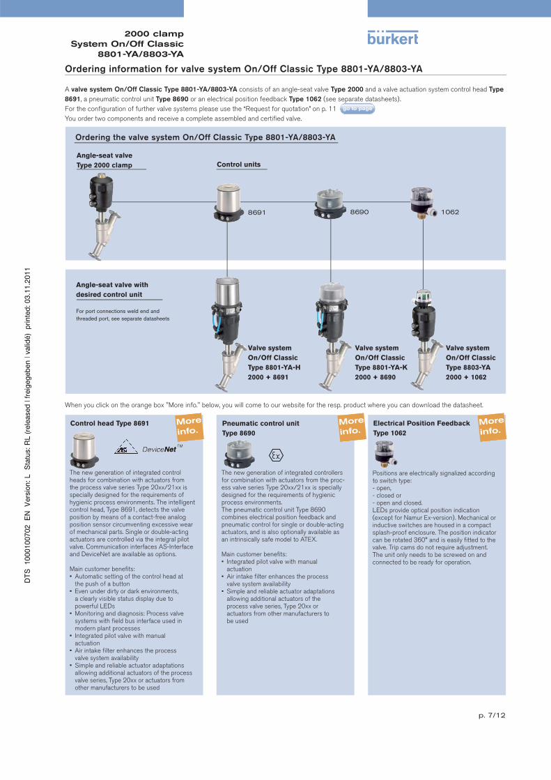
Ordering information for valve system On/Off Classic Type 8801-YA/8803-YA
A valve system On/Off Classic Type 8801-YA/8803-YA consists of an angle-seat valve Type 2000 and a valve actuation system control head Type
8691, a pneumatic control unit Type 8690 or an electrical position feedback Type 1062 (see separate datasheets).
For the confi guration of further valve systems please use the “Request for quotation” on p. 11
You order two components and receive a complete assembled and certifi ed valve.
Control units
Angle-seat valve
Type 2000 clamp
Angle-seat valve with
desired control unit
For port connections weld end and
threaded port, see separate datasheets
Valve system
On/Off Classic
Type 8803-YA
2000 + 1062
Ordering the valve system On/Off Classic Type 8801-YA/8803-YA
1062
Electrical Position Feedback
Type 1062
Positions are electrically signalized according to switch type: - open, - closed or - open and closed. LEDs provide optical position indication (except for Namur Ex-version). Mechanical or inductive switches are housed in a compact splash-proof enclosure. The position indicator can be rotated 360° and is easily fi tted to the valve. Trip cams do not require adjustment. The unit only needs to be screwed on and connected to be ready for operation.
When you click on the orange box "More info." below, you will come to our website for the resp. product where you can download the datasheet.
8690 8691
Pneumatic control unit
Type 8690
The new generation of integrated controllers for combination with actuators from the proc-ess valve series Type 20xx/21xx is specially designed for the requirements of hygienic process environments.The pneumatic control unit Type 8690 combines electrical position feedback and pneumatic control for single or double-acting actuators, and is also optionally available as an intrinsically safe model to ATEX.
Main customer benefi ts:• Integrated pilot valve with manual actuation• Air intake fi lter enhances the process valve system availability• Simple and reliable actuator adaptations allowing additional actuators of the process valve series, Type 20xx or actuators from other manufacturers to be used
Control head Type 8691
The new generation of integrated control heads for combination with actuators from the process valve series Type 20xx/21xx is specially designed for the requirements of hygienic process environments. The intelligent control head, Type 8691, detects the valve position by means of a contact-free analog position sensor circumventing excessive wear of mechanical parts. Single or double-acting actuators are controlled via the integral pilot valve. Communication interfaces AS-Interface and DeviceNet are available as options.
Main customer benefi ts:• Automatic setting of the control head at the push of a button• Even under dirty or dark environments, a clearly visible status display due to powerful LEDs• Monitoring and diagnosis: Process valve systems with fi eld bus interface used in modern plant processes• Integrated pilot valve with manual actuation• Air intake fi lter enhances the process valve system availability• Simple and reliable actuator adaptations allowing additional actuators of the process valve series, Type 20xx or actuators from other manufacturers to be used
Valve system
On/Off Classic
Type 8801-YA-K
2000 + 8690
Valve system
On/Off Classic
Type 8801-YA-H
2000 + 8691

p. 8/12
2000 clampSystem On/Off Classic
8801-YA/8803-YA
Dimensions for valve system On/Off Classic Type 8801-YA-H [mm]
Dimensions valve system On/Off Classic Type 8801-YA-H with TopControl Type 8691 [mm]
Orifi ce Actuator
size
HS BC
[mm] [mm] [mm] [mm]
13 50 234 283.5
20 50 238 295
63 261.5 318.5
25 50 241 299.5
63 263.5 322
80 278.5 337
32 63 273.5 331.5
80 289.5 347.5
40 63 276.5 346
80 293.5 363
100 337.5 407
125 360.5 430
50 63 294.5 372.5
80 310.5 388.5
100 351.5 429.5
125 374.5 452.5
Acc. ISO 2852, BS 4825, ASME BPE, DIN 32676

p. 9/12
2000 clampSystem On/Off Classic
8801-YA/8803-YA
Dimensions for valve system On/Off Classic Type 8801-YA-K [mm]
Dimensions valve system On/Off Classic Type 8801-YA-K with TopControl Type 8690 [mm]
Orifi ce Actuator
size
HS BC
[mm] [mm] [mm] [mm]
13 50 210 259.5
20 50 214 271
63 238 295
25 50 217 275,5
63 239 298.5
80 254.5 313
32 63 250 308
80 265.5 323.5
40 63 253 322.5
80 269.5 339
100 313.5 383
125 336.5 406
50 63 271 349
80 286.5 364.5
100 327.5 405.5
125 350.5 428.5
Acc. ISO 2852, BS 4825, ASME BPE, DIN 32676

p. 10/12
2000 clampSystem On/Off Classic
8801-YA/8803-YA
Dimensions for valve system On/Off Classic Type 8803-YA [mm]
Dimensions valve system On/Off Classic Type 8803-YA with electrical position feedback Type 1062 [mm]
Acc. to EN ISO 2852 [mm]
Orifi ce [mm]
Actuator size ø [mm]
HG[mm]
BG[mm]
15 50 200 249
20 50 204 261
25 50 207 265
63 230 288
32 63 240 298
80 255 313
40 63 243 312
80 259 328
50 63 261 339
100 319 397
Acc. to ASME BPE and BS 4825 [mm]
Orifi ce [mm]
Actuator size ø [mm]
HG[mm]
BG[mm]
15 50 200 249
20 50 204 261
25 50 207 265
63 230 288
40 63 243 312
80 259 328
50 63 261 339
100 319 397

p. 11/12
2000 clampSystem On/Off Classic
8801-YA/8803-YA
Operating data
= mandatory fi elds to fi ll out Quantity Required delivery date
Pipeline
Process medium
Type of medium Liquid Steam Gas
Temperature at valve inlet
Valve features
DN PN
Company Contact person
Customer no. Department
Address Tel./Fax
Postcode/town E-Mail
Valve system On/Off Classic Type 8801-YA/8803-YA – request for quotation
Please fill out and send to your nearest Bürkert facility* with your inquiry or order
standard unitFlow rate (Q, QN, W) 1)
Absolute pressure at valve inlet
Body material
Actuator material
Stainless steel Gunmetal
PA PPS
PTFE NBR OtherSeat sealing material
Nominal pressure PN
Nominal size DN Welded Internal thread ClampType of connection
ISO DIN ANSI JIS OtherStandard connection
NC2) NO 2) Double-actingFunction
min. max.Pilot pressure
1) standard unit: Liquid Q = m3/h; Steam W = kg/h; Gas QN = Nm3/h
2) NC: normally closed by spring action; NO: normally open by spring action
Pipe material
To fi nd your nearest Bürkert facility, click on the orange box www.burkert .com*
Control unit features
Click on the orange box "More info." below... you will come to our website for the resp. product where you can download the datasheet.
continued on next page
Type 8691 Type 8690
Pneumatic function
Single-acting Double-acting
Without pilot valve
Position feedback
Supply voltage
1x inductive 2x inductive
1x inductive (NAMUR) 2x inductive (NAMUR)
1x mechanical 2x mechanical
24 V / DC (ATEX Zone 2/22)
Ex ia IIC T6 (ATEX Zone 1)
Pilot air ports
Push-in connector Thread G 1/8”
external ø 6 mm or 1/4”
Pneumatic function
Single-acting Double-acting
Pilot air ports
Push-in connector external ø 6 mm or 1/4”
Thread G 1/8”
Communication
ASI
Multipol M12
Flat cable clip, 1 m cable
DeviceNet
Please specify item no. if known: Please specify item no. if known:Please specify item no. if known:
Pneumatic Control Unit Control Head Electrical position feedback
Type 1062
Limit switches
mechanical
Voltage 12-48 V
Voltage 110-250 V
inductive
NAMUR EExi
Status
closed
open
open/closed

p. 12/12
2000 clampSystem On/Off Classic
8801-YA/8803-YA
In case of special application conditions,
please consult for advice.
Subject to alterations
© Christian Bürkert GmbH & Co. KG 1110/9_EU-en_00891659
Valve system On/Off Classic Type 8801-YA/8803-YA – request for quotation, continued
Certifications
Attestation of compliance with the order EN-ISO 10204 2.1
Test report EN-ISO 10204 2.2
Certifi cation of Conformity for Raw Material EN-ISO 10204 3.1
EN161 (European Gas Device guideline)
Please specify item no. if known: Please specify item no. if known:
Power supply
Control unit features
Pilot valve
Pilot valve Stroke limitation
Stroke limitation
Min./max. stroke limitation, with visual
position indicator
Max. stroke limitation, without visual
position indicator
Comment / sketch