Embed Size (px)
DESCRIPTION
dSpace Simulation kitdSpace documentationdSpace can be employed for several purposes
Citation preview

Detail Steps of working with DS-1104
To check ADC & DAC Channel:-
Step 1: - Start Matlab (R2010a) and then select dSpace RTI Platform Support RTI1104/1103
Step 2: -· Select Simulation.· Open Model through File → New → Model
For reference I have created a model of “sine.mdl”
1

Step 3: - Now for checking DAC Channel & ADC channel, open RTI Library and select DAC & ADC block.
2

Take DAC & ADC block in to our simulation model and configure as per below figure.
Step:-4· Select Simulation →Configuration parameter.· Select Fixed-step solver and take Fixed-step size 0.001.
3
· Select Code Generation and change setting as per below figure.
4
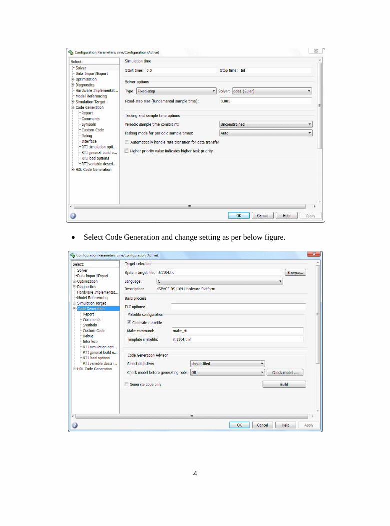
· If we want to automatically “.sdf” load on to working board then select following option.
· Apply the setting.
Step:-5· We have to build the model that we have created· In Matlab where the model is created go to Tools → Real Time Workshop →
Build Model
5

· As the model is build, the process is completed in Matlab as shown below· Following message can be seen → Successful completion of Real → Time
Workshop build procedure for model: “sine”· Finished RTI build procedure for model “sine”.
6
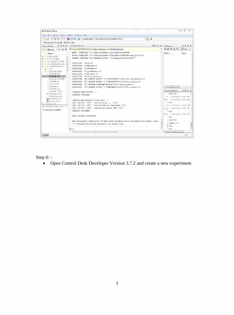
Step 6: -· Open Control Desk Developer Version 3.7.2 and create a new experiment
7

· On creating new experiment the following dialogue box appears as shown below:
8

· In dialogue box give the name of the experiment and working root for the experiment. The experiment is loaded in the control desk. For your reference you can give the description of the experiment too.
Step 7: -· Open the platform manager in the control desk
9

· Open the file selector command in control desk.(As per you’re working directory in MATLAB)
· On opening (on the left) open C Drive → Users → xyz → My Documents → Matlab
(on the right) – locate the file in the format (.sdf). Drag the sdf file on to the DS1104
After dragging the file following window will appear as shown below:
10

· Click ‘Yes’ on the dialogue box· The following changes in the window you can see below:
· In this new window the whole model blocks you can observe. It shows each block of the model with the input, outputs and etc.
Step 8: -
11

· In the control desk create a new layout. File → New → Layout
· After creating a new layout you can add the various parameter blocks in the layout. Different Blocks are located in right hand side of the control desk.
· From Instrument Panel select Plotter and drop on to layout.· From Tool window, select input and output variable for ADC & DAC and drag
& drop in to plotter as per below figure.
· To add a block in the layout, steps carried out are: -· Click on the block that you want to add to the layout· Click on the layout with the left mouse button holding and drag the
cursor on the layout and then leave the mouse buttonStep:-9
· Now from Upper side of window the Animation Mode switch is given, press it and run the simulation model.
· Observe the output in the layout by dragging the blocks as shown in the figure below:
12

· In this way various outputs can be observed by dragging the block in the display section.
To check Digital I/O:-
Step 1: - Start Matlab (R2010a) and then select dSPACE RTI Platform Support RTI1104/1103
13

Step 2: -· Select Simulation.· Open Model through File → New → Model· For reference I have created a model of “bit.mdl”
14

Step 3: - Now for checking BIT I/O Channel open RTI Library and select MASTER BIT OUT block.
Take MASTER BIT I/O block in to your simulation model and configure as per below figure.
15
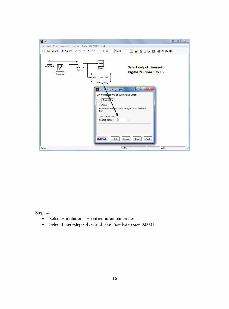
Step:-4· Select Simulation →Configuration parameter.· Select Fixed-step solver and take Fixed-step size 0.0001.
16

· Select Code Generation and change setting as per below figure.
17
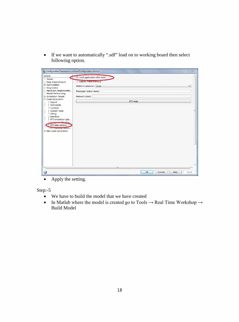
· If we want to automatically “.sdf” load on to working board then select following option.
· Apply the setting.
Step:-5· We have to build the model that we have created· In Matlab where the model is created go to Tools → Real Time Workshop →
Build Model
18

· As the model is build, the process is completed in Matlab as shown below· Following message can be seen → Successful completion of Real → Time
Workshop build procedure for model: “bit”· Finished RTI build procedure for model “bit”.
19
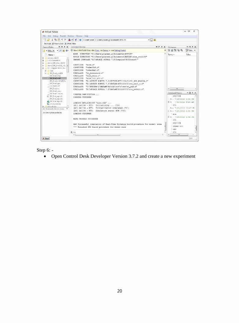
Step 6: -· Open Control Desk Developer Version 3.7.2 and create a new experiment
20

· On creating new experiment the following dialogue box appears as shown below:
21
· In dialogue box give the name of the experiment and working root for the experiment. The experiment is loaded in the control desk. For your reference you can give the description of the experiment too.
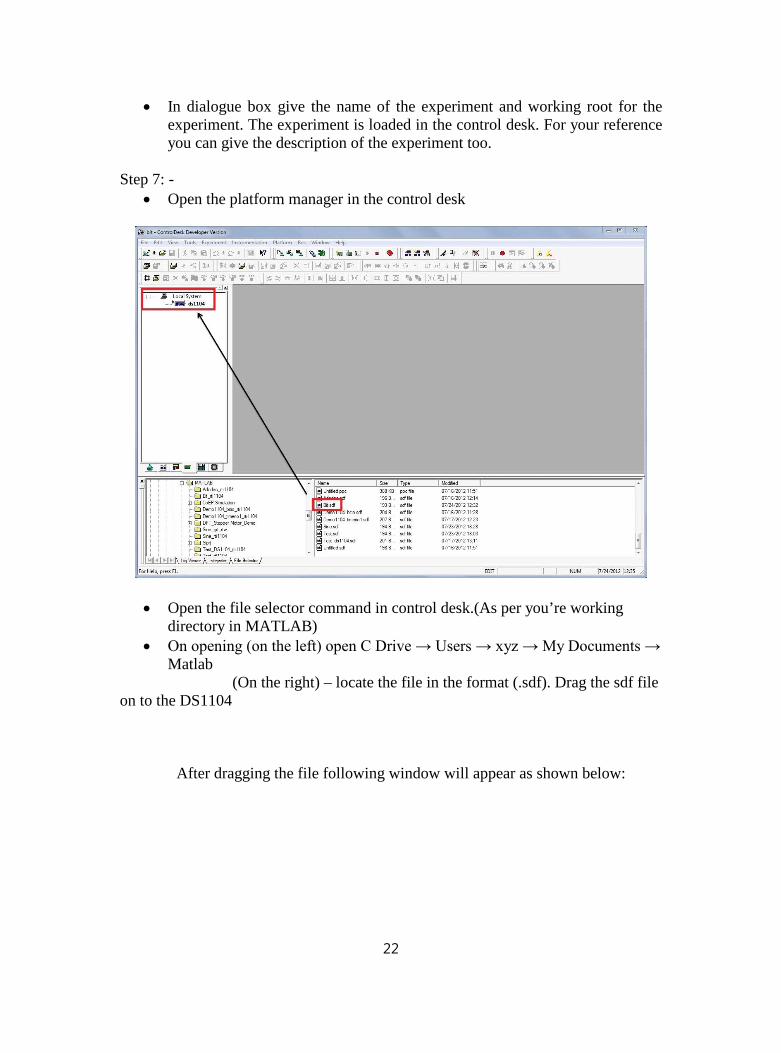
Step 7: -· Open the platform manager in the control desk
· Open the file selector command in control desk.(As per you’re working directory in MATLAB)
· On opening (on the left) open C Drive → Users → xyz → My Documents → Matlab
(On the right) – locate the file in the format (.sdf). Drag the sdf file on to the DS1104
After dragging the file following window will appear as shown below:
22

· Click ‘Yes’ on the dialogue box
· The following changes in the window you can see below:
23
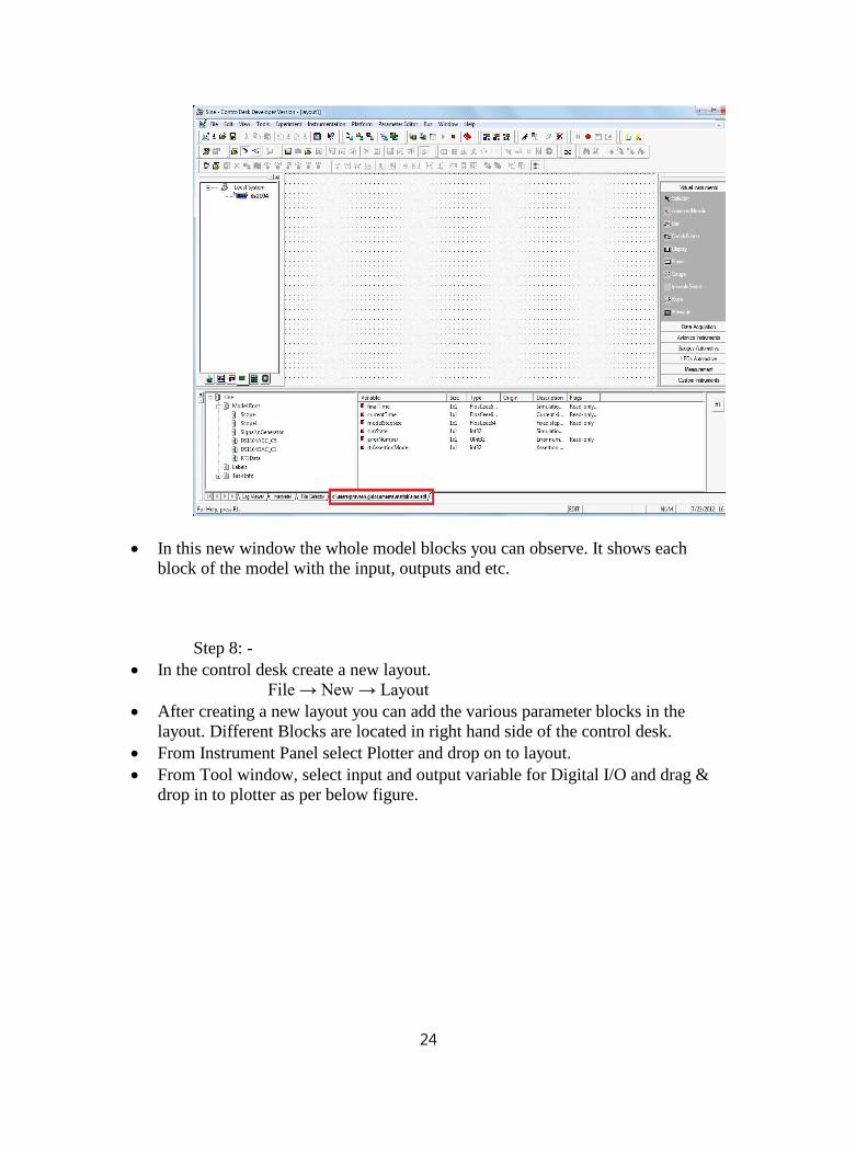
· In this new window the whole model blocks you can observe. It shows each block of the model with the input, outputs and etc.
Step 8: -· In the control desk create a new layout.
File → New → Layout· After creating a new layout you can add the various parameter blocks in the
layout. Different Blocks are located in right hand side of the control desk.· From Instrument Panel select Plotter and drop on to layout.· From Tool window, select input and output variable for Digital I/O and drag &
drop in to plotter as per below figure.
24

· To add a block in the layout, steps carried out are: -· Click on the block that you want to add to the layout· Click on the layout with the left mouse button holding and drag the
cursor on the layout and then leave the mouse button
25
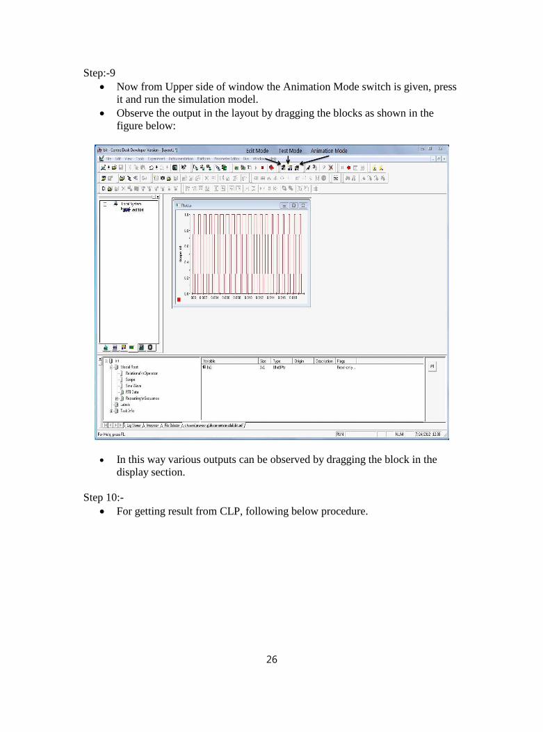
Step:-9· Now from Upper side of window the Animation Mode switch is given, press
it and run the simulation model.· Observe the output in the layout by dragging the blocks as shown in the
figure below:
· In this way various outputs can be observed by dragging the block in the display section.
Step 10:-· For getting result from CLP, following below procedure.
26
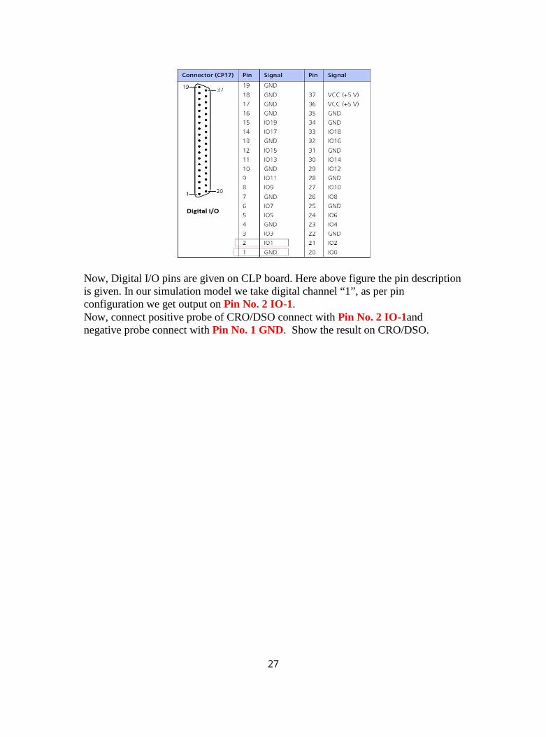
Now, Digital I/O pins are given on CLP board. Here above figure the pin description is given. In our simulation model we take digital channel “1”, as per pin configuration we get output on Pin No. 2 IO-1.Now, connect positive probe of CRO/DSO connect with Pin No. 2 IO-1and negative probe connect with Pin No. 1 GND. Show the result on CRO/DSO.
27