Embed Size (px)
Citation preview
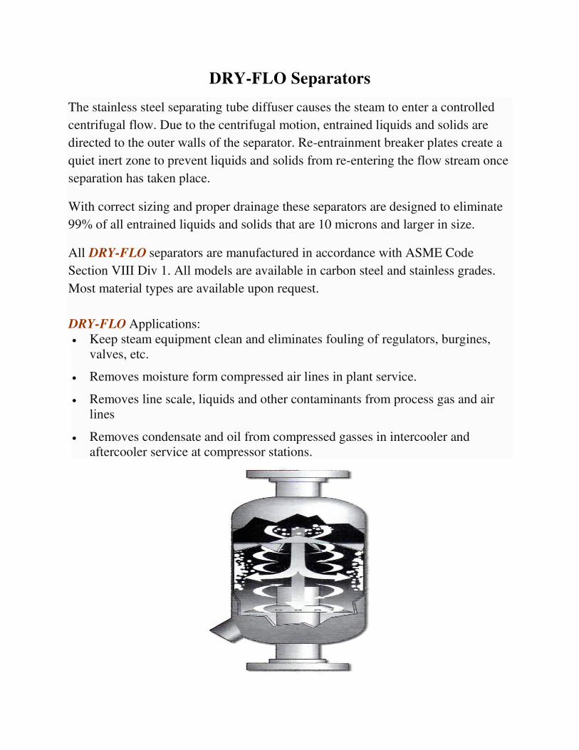
DRY-FLO Separators
The stainless steel separating tube diffuser causes the steam to enter a controlled
centrifugal flow. Due to the centrifugal motion, entrained liquids and solids are
directed to the outer walls of the separator. Re-entrainment breaker plates create a
quiet inert zone to prevent liquids and solids from re-entering the flow stream once
separation has taken place.
With correct sizing and proper drainage these separators are designed to eliminate
99% of all entrained liquids and solids that are 10 microns and larger in size.
All DRY-FLO separators are manufactured in accordance with ASME Code
Section VIII Div 1. All models are available in carbon steel and stainless grades.
Most material types are available upon request.
DRY-FLO Applications:
Keep steam equipment clean and eliminates fouling of regulators, burgines,
valves, etc.
Removes moisture form compressed air lines in plant service.
Removes line scale, liquids and other contaminants from process gas and air
lines
Removes condensate and oil from compressed gasses in intercooler and
aftercooler service at compressor stations.
CIRCLE
PRODUCTS, INC.
TECHNICAL BULLETIN
PHONE 734-675-2960 FAX 734-675-6577 www.dryflo.com
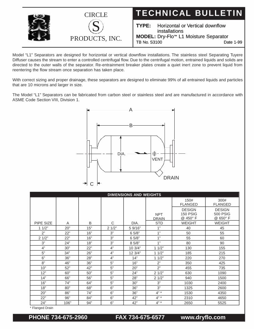
TYPE: Horizontal or Vertical downflowinstallations
MODEL: Dry-Flo™ L1 Moisture SeparatorTB No. S3100 Date 1-99
S TYPE: Horizontal or Vertical downflowinstallations
MODEL: Dry-Flo™ L1 Moisture SeparatorTB No. S3100 Date 1-99
Model “L1” Separators are designed for horizontal or vertical downflow installations. The stainless steel Separating TuyereDiffuser causes the stream to enter a controlled centrifugal flow. Due to the centrifugal motion, entrained liquids and solids aredirected to the outer walls of the separator. Re-entrainment breaker plates create a quiet inert zone to prevent liquid fromreentering the flow stream once separation has taken place.
With correct sizing and proper drainage, these separators are designed to eliminate 99% of all entrained liquids and particlesthat are 10 microns and larger in size.
The Model “L1” Separators can be fabricated from carbon steel or stainless steel and are manufactured in accordance withASME Code Section VIII, Division 1.
150#FLANGED
DESIGN150 PSIG@ 450° F
NPTDRAIN
300#FLANGED
DESIGN500 PSIG@ 650° F
PIPE SIZE1 1/2”
2”2 1/2”
3”4”5”6”8”10”12”14”16”18”20”22”24”
20”22”22”24”30”34”36”46”52”60”66”74”80”86”96”106”
15”16”16”18”22”26”28”36”42”50”56”64”68”74”84”94”
2 1/2”3”3”3”4”4”4”5”5”5”5”5”6”6”6”6”
5 9/16”6 5/8”6 5/8”8 5/8”10 3/4”12 3/4”
14”16”20”24”28”30”36”36”42”42”
1”1”1”1”
1 1/2”1 1/2”1 1/2”
2”2”
2 1/2”2 1/2”
3”3”
4” *4” *4” *
4050558013018522035045563094010301325153023102650
455560901552152704257351090150024002600435046505525
A B C DIA. STD WEIGHT WEIGHT
DRAIN
VENT
A
B
C
DIA.
* Flanged Drain
DIMENSIONS AND WEIGHTS

CIRCLE
PRODUCTS, INC.
TECHNICAL BULLETIN
PHONE 734-675-2960 FAX 734-675-6577 www.dryflo.com
TYPE: Horizontal installations
MODEL: Dry-Flo™ L1S Moisture SeparatorTB No. S3150 Date 1-99
S
150#FLANGEDDESIGN150 PSIG@ 450° F
NPTDRAIN
LIQUIDHOLDUP
300#FLANGEDDESIGN500 PSIG@ 650° FPIPE
SIZE1 1/2”
2”2 1/2”
3”4”5”6”8”10”12”14”16”18”20”22”24”
20”22”22”24”30”34”36”46”52”60”66”74”80”86”96”106”
15”16”16”18”22”26”28”36”42”50”56”64”68”74”84”94”
2 1/2”3”3”3”4”4”4”5”5”5”5”5”6”6”6”6”
5 9/16”6 5/8”6 5/8”8 5/8”
10 3/4”12 3/4
14”16”20”24”28”30”36”36”42”42”
1” 0.010.020.020.030.070.080.130.270.430.520.660.831.261.782.292.43
1”1”1”
1 1/2”1 1/2”1 1/2”
2”2”
2 1/2”2 1/2”
3”3”
4” *4” *4” *
43536089
142209245402506699
103011501472169225492943
505868
102172248307476826
1207166226712868480951366110
A B C DIA.14”
14 1/2”14 1/2”16 1/2”17 1/2”19 1/2”
21”24”27”30”33”35”39”42”46”47”
E8 1/2”
9”9”
10”12”1314”16”19”23”23”24”27”28”31”31”
F6 3/4”6 3/4”6 3/4”6 3/4”6 3/4”6 3/4”6 3/4”7 7/8”7 7/8”7 7/8”7 7/8”7 7/8”9 1/8”9 1/8”
10 1/4”10 1/4”
G2 3/8”2 7/8”2 7/8”3 1/2”4 1/2”
5 9/16”6 5/8”8 5/8”
10 3/4”10 3/4”12 3/4”
14”16”18”20”20”
H STD CU. FT. WEIGHT WEIGHT
* Flanged Drain
DIMENSIONS AND WEIGHTS
Model “L1S” Separators are designed f or horizontal flow installations and are similar to the Model “L1” Separators with theaddition of a sump area to allow for a liquid hold-up capacity. If required, the sump area may be lengthened from the standarddimensions shown below to allow for a larger liquid hold-up capacity . The stainless steel Separating Tuyere Diffuser causesthe stream to enter a controlled centrifugal flow. Due to the centrifugal motion, entrained liquids and solids are directed to theouter walls of the separator. Re-entrainment breaker plates create a quiet inert zone to prevent liquid from re-entering the flowstream once separation has taken place.
With correct sizing and proper drainage, these separators are designed to eliminate 99% of all entrained liquids and particlesthat are 10 microns and larger in siz e.
The Model “L1S” Separators can be fabricated from carbon steel or stainless s teel and are manufactured in accordance withthe ASME Code Section VIII, Division 1.

CIRCLE
PRODUCTS, INC.
TECHNICAL BULLETIN
PHONE 734-675-2960 FAX 734-675-6577 www.dryflo.com
TYPE: Vertical Upflow installations
MODEL: Dry-Flo™ L2 Moisture SeparatorTB No. S3200 Date 1-99
S
Model “L2” Separators are designed for vertical upflow installations only. The stainless steel Separating Tuyere Diffusercauses the stream to enter a controlled centr ifugal flow. Due to the centrifugal motion, entrained liquids and solids aredirected to the outer walls of the separator. Re-entrainment breaker plates create a quiet iner t zone to prevent liquid fromreentering the flow stream once separation has taken place.
With correct sizing and proper drainage, these separators are designed to eliminate 99% of all entr ained liquids andparticles that are 10 microns and larger in siz e.
The Model “L2” Separators can be fabricated from carbon steel or stainless steel and are manufactured in accordance withthe ASME Code Section VIII, Division I.
BDIA.
A
VENT
DRAIN
150#FLANGEDDESIGN150 PSIG@ 450° F
NPTDRAIN
300#FLANGEDDESIGN500 PSIG@ 650° F
PIPE SIZE1 1/2”
2”2 1/2”
3”4”5”6”8”10”12”14”16”18”20”22”24”
17”19”19”22”28”30”33”39”48”54”60”66”72”78”83”88”
12”13”13”16”20”22”25”29”38”44”50”56”60”66”71”76”
2 1/2” 3”3”3”4”4”4”5”5”5”5”5”6”6”6”6”
6 5/8”8 5/8”8 5/8”
10 3/4”14”16”18”20”24”30”36”40”42”48”48”54”
1”1”1”1”
1 1/2”1 1/2”1 1/2”
2”2”
2 1/2”2 1/2”
3”3”
4” *4” *4” *
506070
100150175225255495700
104011701475169025482800
6095
100135280380460620825
1207160026003280375056606220
A B C DIA. STD WEIGHT WEIGHT
* Flanged Drain
DIMENSIONS AND WEIGHTS
C

CIRCLE
PRODUCTS, INC.
TECHNICAL BULLETIN
PHONE 734-675-2960 FAX 734-675-6577 www.dryflo.com
TYPE: Vertical down / Horizontal outflow installations
MODEL: Dry-Flo™ L3 Moisture SeparatorTB No. S3300 Date 1-99
S
Model “L3” Separators are designed for vertical down and a horizontal out flow installation only.The stainless steel Separating Tuyere Diffuser causes the stream to enter a controlled centr ifugal flow. Due to the centrifugal motion, entrained liquids and solids are directed to the outer w alls of the separ ator. Re-entrainment breaker plates create a quiet inert zone to prevent liquid from re-entering the flow stream once separation has taken place.
With correct sizing and proper drainage, these separators are designed to eliminate 99% of all entrained liquids and particles that are 10 microns and larger in siz e.
The Model “L3” Separators can be fabricated from carbon steel or stainless steel and are manufactured in accordance withthe ASME Code Section VIII, Division I.
150#FLANGEDDESIGN150 PSIG@ 450° F
NPTDRAIN
300#FLANGEDDESIGN500 PSIG@ 650° F
PIPE SIZE1 1/2”
2”2 1/2”
3”4”5”6”8”10”12”14”16”18”20”22”24”
16”18”18”21”25”30”34”41”50”58”65”74”85”92”
101”108”
5 1/2”7”7”8”
10”11”12”13”15”17”19”20”24”24”27”27”
12 1/2”14”14”16”20”24”27”33”40”46”52”59”68”74”81”81”
2 1/2”3”3”3”4”4”4”5”5”5”5”5”6”6”6”6”
5 9/16”6 5/8”6 5/8”8 5/8”
10 3/4”12 3/4”
14”16”20”24”28”30”36”36”42”42”
1”1”1”1”
1 1/2”1 1/2”1 1/2”
2”2”
2 1/2”2 1/2”
3”3”
4” *4” *4” *
41505784
134198232380478660973
10871392160024102782
47556497162234290450781
1141157125252711454748565777
R S TC DIA. STD WEIGHT WEIGHT
* Flanged Drain
DIMENSIONS AND WEIGHTS
S
T
C
RDIA.
VENT
DRAIN
CIRCLE
PRODUCTS, INC.
TECHNICAL BULLETIN
PHONE 734-675-2960 FAX 734-675-6577 www.dryflo.com
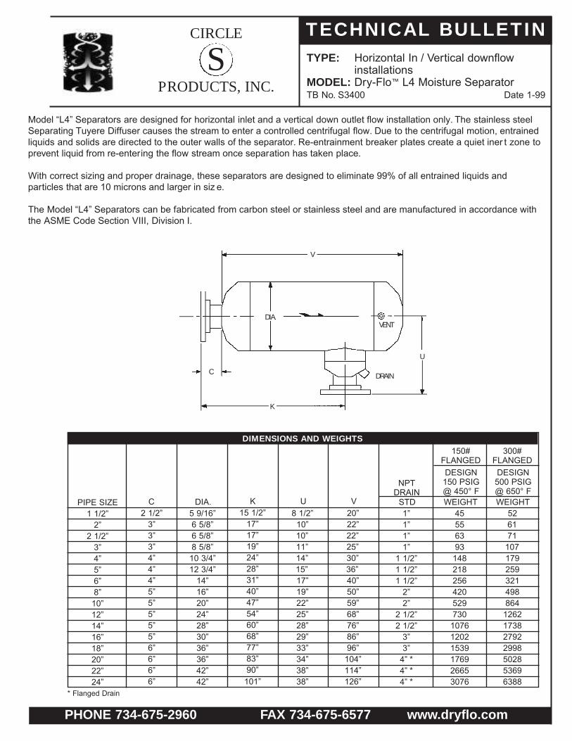
TYPE: Horizontal In / Vertical downflowinstallations
MODEL: Dry-Flo™ L4 Moisture SeparatorTB No. S3400 Date 1-99
S
Model “L4” Separators are designed for horizontal inlet and a vertical down outlet flow installation only. The stainless steel Separating Tuyere Diffuser causes the stream to enter a controlled centrifugal flow. Due to the centrifugal motion, entrained liquids and solids are directed to the outer walls of the separator. Re-entrainment breaker plates create a quiet iner t zone to prevent liquid from re-entering the flow stream once separation has taken place.
With correct sizing and proper drainage, these separators are designed to eliminate 99% of all entrained liquids and particles that are 10 microns and larger in siz e.
The Model “L4” Separators can be fabricated from carbon steel or stainless steel and are manufactured in accordance withthe ASME Code Section VIII, Division I.
150#FLANGEDDESIGN150 PSIG@ 450° F
NPTDRAIN
300#FLANGEDDESIGN500 PSIG@ 650° F
PIPE SIZE1 1/2”
2”2 1/2”
3”4”5”6”8”10”12”14”16”18”20”22”24”
8 1/2”10”10”11”14”15”17”19”22”25”28”29”33”34”38”38”
20”22”22”25”30”36”40”50”59”68”76”86”96”
104”114”126”
15 1/2”17”17”19”24”28”31”40”47”54”60”68”77”83”90”
101”
2 1/2”3”3”3”4”4”4”5”5”5”5”5”6”6”6”6”
5 9/16”6 5/8”6 5/8”8 5/8”
10 3/4”12 3/4”
14”16”20”24”28”30”36”36”42”42”
1”1”1”1”
1 1/2”1 1/2”1 1/2”
2”2”
2 1/2”2 1/2”
3”3”
4” *4” *4” *
45556393
148218256420529730
107612021539176926653076
526171
107179259321498864
1262173827922998502853696388
K U VC DIA. STD WEIGHT WEIGHT
* Flanged Drain
DIMENSIONS AND WEIGHTS
V
C
DIA.VENT
DRAIN
K
U

CIRCLE
PRODUCTS, INC.
TECHNICAL BULLETIN
PHONE 734-675-2960 FAX 734-675-6577 www.dryflo.com
TYPE: Horizontal In / Vertical Upflowinstallations
MODEL: Dry-Flo™ L5 Mositure SeparatorTB No. S3500 Date 1-99
S
Model “L5” Separators are designed for horizontal inlet and a vertical upflow installation only. The stainless steel SeparatingTuyere Diffuser causes the stream to enter a controlled centr ifugal flow. Due to the centrifugal motion, entrained liquids andsolids are directed to the outer walls of the separator. Re-entrainment breaker plates create a quiet iner t zone to preventliquid from re-entering the flow stream once separation has taken place.
With correct sizing and proper drainage, these separators are designed to eliminate 99% of all entrained liquids and particles that are 10 microns and larger in siz e.
The Model “L5” Separators can be fabricated from carbon steel or stainless steel and are manufactured in accordance with the ASME Code Section VIII, Division I.
150#FLANGEDDESIGN150 PSIG@ 450° F
NPTDRAIN
300#FLANGEDDESIGN500 PSIG@ 650° F
PIPE SIZE1 1/2”
2”2 1/2”
3”4”5”6”8”10”12”14”16”18”20”22”24”
19”20”20”26”28”33”37”45”54”66”73”85”90”97”
105”113”
6”8”8”9”
11”12”13”15”17”20”23”25”27”30”30”33”
15”16”16”21”23”27”30”37”44”52”58”68”72”78”84”90”
2 1/2”3”3”3”4”4”4”5”5”5”5”5”6”6”6”6”
6 5/8”8 5/8”8 5/8”
10 3/4”14”16”18”20”24”30”36”40”42”48”48”54”
1”1”1”1”
1 1/2”1 1/2”1 1/2”
2”2”
2 1/2”2 1/2”
3”3”
4” *4” *4” *
607397
147198287350524746
1063141819722353254731963730
6677
103157216334480652
1050156823203290
E F GC DIA. STD WEIGHT WEIGHT
* Flanged Drain
DIMENSIONS AND WEIGHTS
DIA.
C
VENT
DRAIN
E
F
G

CIRCLE
PRODUCTS, INC.
TECHNICAL BULLETIN
PHONE 734-675-2960 FAX 734-675-6577 www.dryflo.com
TYPE: Horizontal In / Vertical downflowinstallations
MODEL: Dry-Flo™ L6 Moisture SeparatorTB No. S3600 Date 1-99
S
Model “L6” Separators are designed for horizontal inlet and vertical down outlet or vertical up inlet and horizontal outlet flow installation only. The stainless steel Separating Tuyere Diffuser causes the stream to enter a controlled centrifugal flow. Due to the centrifugal motion, entrained liquids and solids are directed to the outer walls of the separator. Re-entrainment break-er plates create a quiet iner t zone to prevent liquid from reentering the flow stream once separation has taken place.
With correct sizing and proper drainage, these separators are designed to eliminate 99% of all entrained liquids and particles that are 10 microns and larger in siz e.
The Model “L6” Separators can be fabricated from carbon steel or stainless steel and are manufactured in accordance with the ASME Code Section VIII, Division I.
150#FLANGEDDESIGN150 PSIG@ 450° F
NPTDRAIN
300#FLANGEDDESIGN500 PSIG@ 650° F
PIPE SIZE1 1/2”
2”2 1/2”
3”4”5”6”8”10”12”14”16”18”20”22”24”
24”26”26”29”36”41”45”58”68”79”89”99”
109”118”131”144”
18”20”20”22”28”32”35”46”54”63”71”80”87”95”
108”117”
5 1/2”7”7”8”
10”11”12”13”15”17”19”20”24”24”27”27”
2 1/2”3”3”3”4”4”4”5”5”5”5”5”6”6”6”6”
5 9/16”6 5/8”6 5/8”8 5/8”
10 3/4”12 3/4”
14”16”20”24”28”30”36”36”42”42”
1”1”1”1”
1 1/2”1 1/2”1 1/2”
2”2”
2 1/2”2 1/2”
3”3”
4” *4” *4” *
47586697
155228268438552762
112312541606184627803210
546474
112187270335520901
1316181329143128524656036666
T W XC DIA. STD WEIGHT WEIGHT
* Flanged Drain
DIMENSIONS AND WEIGHTS
T
W
C
X
DIA.VENT
DRAIN
CIRCLE
PRODUCTS, INC.
TECHNICAL BULLETIN
PHONE 734-675-2960 FAX 734-675-6577 www.dryflo.com
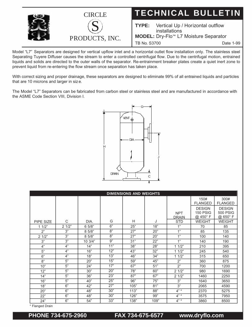
TYPE: Vertical Up / Horizontal outflowinstallations
MODEL: Dry-Flo™ L7 Moisture SeparatorTB No. S3700 Date 1-99
S
Model “L7” Separators are designed for vertical upflow inlet and a horizontal outlet flow installation only. The stainless steel Separating Tuyere Diffuser causes the stream to enter a controlled centrifugal flow. Due to the centrifugal motion, entrained liquids and solids are directed to the outer walls of the separator. Re-entrainment breaker plates create a quiet inert zone to prevent liquid from re-entering the flow stream once separation has taken place.
With correct sizing and proper drainage, these separators are designed to eliminate 99% of all entrained liquids and particlesthat are 10 microns and larger in siz e.
The Model “L7” Separators can be fabricated from carbon steel or stainless steel and are manufactured in accordance with the ASME Code Section VIII, Division I.
150#FLANGEDDESIGN150 PSIG@ 450° F
NPTDRAIN
300#FLANGEDDESIGN500 PSIG@ 650° F
PIPE SIZE1 1/2”
2”2 1/2”
3”4”5”6”8”10”12”14”16”18”20”22”24”
25”27”27”31”38”43”46”59”67”78”87”96”
105”113”126”138”
18”20”20”22”28”32”34”45”51”60”67”75”81”88”99”
109”
6”8”8”9”
11”12”13”15”17”20”23”25”27”30”30”33”
2 1/2”3”3”3”4”4”4”5”5”5”5”5”6”6”6”6”
6 5/8”8 5/8”8 5/8”
10 3/4”14”16”18”20”24”30”36”40”42”48”48”54”
1”1”1”1”
1 1/2”1 1/2”1 1/2”
2”2”
2 1/2”2 1/2”
3”3”
4” *4” *4” *
7085
100140210245315360700980
146016402065237035753860
85135140190395540650875
12001690225036504590527579508500
G H JC DIA. STD WEIGHT WEIGHT
* Flanged Drain
DIMENSIONS AND WEIGHTS
H
DIA.
DRAIN
VENT
G
C
J

CIRCLE
PRODUCTS, INC.
TECHNICAL BULLETIN
PHONE 734-675-2960 FAX 734-675-6577 www.dryflo.com
TYPE: Horizontal flowinstallations only
MODEL: Dry-Flo™ T Moisture SeparatorTB No. S3800 Date 1-99
S
Gas, laden with moisture, enters the inlet of the separator where a deflector plate directs the flow in a downward centrifugal motion. The entrained moisture is then separated out of the flow by a reduction in velocity. The separated liquid is sent to the outer walls of the separator and falls below the re-entrainment breaker plate where it is prevented for re-entering the flow stream. A dry, clean flow then results, exiting upward through the outlet of the separator.
With correct sizing and proper drainage, these separators are designed to eliminate 99% of all entrained liquids and particlesthat are 10 microns and larger in siz e.
The Model “T” Separators can be fabricated from carbon steel or stainless steel and are manufactured in accordance with theASME Code Section VIII, Division I.
150#FLANGED
THREADED ORSOCKET WELD
DESIGN150 PSIG@ 450° F
DESIGNCUSTOMER
SPECIFICATIONSNPT
DRAIN
300#FLANGEDDESIGN500 PSIG@ 650° FPIPE
SIZE1”
1 1/4”1 1/2”
2”2 1/2”
3”4”5”6”8”10”12”14”16”18”20”
16”16”19”19”22”26”31”36”41”50”70”75”79”89”
109”126”
5 3/4”5 3/4”7 7/8”7 7/8”7 7/8”7 7/8”7 7/8”7 7/8”7 7/8”9 1/8”9 1/8”
10 1/2”10 1/2”11 1/2”11 1/2”
16”18”20”22”24”28”34”38”42”47”54”62”
10 1/2”10 1/2”12 1/2”12 1/2”
15”18”22”26”30”37”55”58”60”68”85”99”
6 3/8”6 3/8”7 5/8”7 7/8”
------------
5 9/16”5 9/16”6 5/8”6 5/8”8 5/8”
10 3/4”12 3/4”
14”16”18”24”28”32”36”42”48”
1”1”1”1”1”1”
1 1/2”1 1/2”1 1/2”
2”2”
2 1/2”2 1/2”
3”3”3”
33355055
100140195230350475780940
1155160522602845
35375659110150220290380610
118015102205278543705635
22” 130” 10 1/4”64” 102”- 48” 3” 3000 608524” 140” 10 1/4”70” 109”-
29305557--------------54” 4” * 4295 7845
150#&
300#FLANGED
A CB G
THREADEDOR
SOCKETWELD
A DIA. STD WEIGHTWEIGHT WEIGHT
* Flanged Drain
DIMENSIONS AND WEIGHTS
CC
B BG
G
A
VENTVENT
DIA.
DRAIN
DRAIN
DIA.
A

CIRCLE
PRODUCTS, INC.
TECHNICAL BULLETIN
PHONE 734-675-2960 FAX 734-675-6577 www.dryflo.com
TYPE: Horizontal flowinstallations only
MODEL: Dry-Flo™ TS Moisture SeparatorTB No. S3850 Date 1-99
S
Gas, laden with moisture, enters the inlet of the separ ator where a deflector plate directs the flow in a downward centrifugalmotion. The entrained moisture is then separated out of the flow by a reduction in velocity. The separated liquid is sent to theouter walls of the separ ator and falls below the re-entrainment breaker plate where it is prevented for re-entering the flowstream. The addition of a sump area will allow for a liquid hold-up capacity . A dry, clean flow then results , exiting upwardthrough the outlet of the separator.
With correct sizing and proper drainage, these separators are designed to eliminate 99% of all entrained liquids and particlesthat are 10 microns and larger in siz e.
The Model “TS” Separators can be fabricated from carbon steel or stainless steel and are man ufactured in accordance withthe ASME Code Section VIII, Division I.
150#FLANGEDDESIGN150 PSIG@ 450° F
NPTDRAIN
300#FLANGEDDESIGN500 PSIG@ 650° FPIPE
SIZE1”
1 1/4”1 1/2”
2”2 1/2”
3”4”5”6”8”10”12”14”16”18”20”
28”28”30”30”35”38”45”50”66”75”91”99”
108”119”132”145”
9 1/8”10 1/4”10 1/4”10 1/4”11 7/8”11 7/8”11 7/8”12 5/8”12 5/8”12 5/8”
15”
10 1/2”10 1/2”11 1/2”11 1/2”
16”18”20”22”24”28”34”38”42”47”54”62”
22”22”24”24”27”30”36”40”55”62”76”82”89”98”108”118”
5 9/16”5 9/16”6 5/8”6 5/8”8 5/8”
10 3/4”12 3/4”
14”16”18”24”28”32”36”42”48”
1”1”1”1”1”1”
1 1/2”1 1/2”1 1/2”
2”2”
2 1/2”2 1/2”
3”3”3”
47506974
122170225265400545800
10901335185026003275
49527578132180250335435700
135517352535320050256480
22” 149” 15”64” 121”48” 3” 3450 700024” 158” 15”70” 129”54” 4” * 4940 9020
FLANGEDA CB GDIA. STD WEIGHT WEIGHT
LIQUIDHOLD-UPCAPACITY
(CUBICFEET)
0.190.190.20.20.390.661.071.353.033.836.94
11.7416.8120.2222.9926.4726.4732.64
* Flanged Drain
DIMENSIONS AND WEIGHTS
OPTIONAL SUPPORTS
FOUR ANGLE LEGSw/ BASE PLATES
SKIRT w/ FOURACCESS OPENINGSEQUALLY SPACED
VENT
DIA.
G
18”C
B
DRAIN
A
CIRCLE
PRODUCTS, INC.
TECHNICAL BULLETIN
PHONE 734-675-2960 FAX 734-675-6577 www.dryflo.com
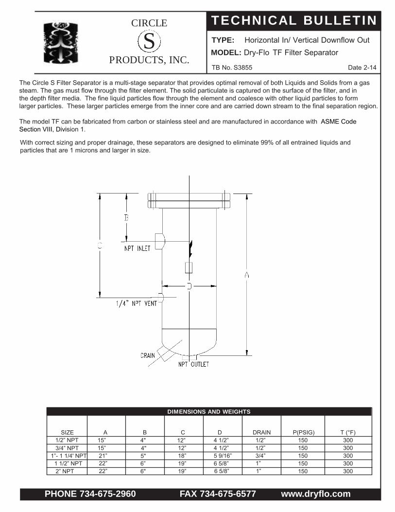
TYPE: Horizontal In/ Vertical Downflow Out MODEL: Dry-Flo TF Filter Separator
TB No. S3855 Date 2-14
S
The Circle S Filter Separator is a multi-stage separator that provides optimal removal of both Liquids and Solids from a gassteam. The gas must flow through the filter element. The solid particulate is captured on the surface of the filter, and inthe depth filter media. The fine liquid particles flow through the element and coalesce with other liquid particles to formlarger particles. These larger particles emerge from the inner core and are carried down stream to the final separation region.
The model TF can be fabricated from carbon or stainless steel and are manufactured in accordance with ASME Code Section VIII, Division 1.
With correct sizing and proper drainage, these separators are designed to eliminate 99% of all entrained liquids and particles that are 1 microns and larger in size.
SIZE 1/2” NPT3/4” NPT
1”- 1 1/4' NPT1 1/2” NPT2” NPT
15”15” 21” 22” 22”
4" 4" 5" 6” 6"
12” 12” 18” 19” 19”
4 1/2”4 1/2”5 9/16”6 5/8”6 5/8”
1/2” 1/2” 3/4” 1” 1”
150150150150150
300300300300300
A B C D DRAIN P(PSIG) T (°F)
DIMENSIONS AND WEIGHTS
CIRCLE
PRODUCTS, INC.
TECHNICAL BULLETIN
PHONE 734-675-2960 FAX 734-675-6577 www.dryflo.com
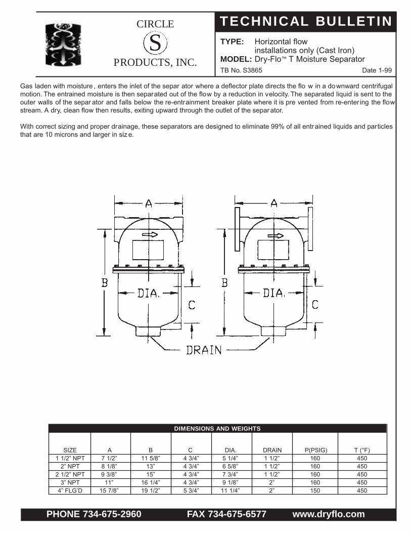
TYPE: Horizontal flowinstallations only (Cast Iron)
MODEL: Dry-Flo™ T Moisture SeparatorTB No. S3865 Date 1-99
S
Gas laden with moisture , enters the inlet of the separ ator where a deflector plate directs the flo w in a downward centrifugalmotion. The entrained moisture is then separated out of the flow by a reduction in velocity. The separated liquid is sent to theouter walls of the separ ator and falls below the re-entrainment breaker plate where it is pre vented from re-enter ing the flowstream. A dry, clean flow then results, exiting upward through the outlet of the separator.
With correct sizing and proper drainage, these separators are designed to eliminate 99% of all entrained liquids and particlesthat are 10 microns and larger in siz e.
SIZE1 1/2” NPT
2” NPT2 1/2” NPT
3” NPT4” FLG’D
7 1/2”8 1/8”9 3/8”
11”15 7/8”
11 5/8”13”15”
16 1/4”19 1/2”
4 3/4”4 3/4”4 3/4”4 3/4”5 3/4”
5 1/4”6 5/8”7 3/4”9 1/8”
11 1/4”
1 1/2”1 1/2”1 1/2”
2”2”
160160160160150
450450450450450
A B C DIA. DRAIN P(PSIG) T (°F)
DIMENSIONS AND WEIGHTS

CIRCLE
PRODUCTS, INC.
TECHNICAL BULLETIN
PHONE 734-675-2960 FAX 734-675-6577 www.dryflo.com
TYPE: Horizontal
MODEL: Dry-Flo™ CS Moisture SeparatorTB No. S3875 Date 1-99
S
• Dry-Flo model CS separators are cast iron which meets ASTM-A-278 Class 35 standards.• All pressure parts are designed and built to meet ASME Code, Section VIII for unfired pressure vessels.• Removes over 99% of all particulates in excess of 10 microns in size over a wide range of flow rates.• Compact trap design features stainless steel moving parts and permits easy access for service.
Manual draining is also available.• Unit is lightweight — can be supported by just the piping.• Optional heating element prevents freezing.
A.50”.75”1.00”1.25”1.50”2.00”2.50”3.00”
--
2.75”2.75”3.00”3.00”3.75”4.06”4.68”5.50”7.13”7.94”
5.50”5.50”6.00”6.00”7.50”8.13”9.38”11.00”14.25”15.88”
11.88”11.88”13.63”13.63”13.63”15.38”19.38”20.88”20.38”23.50”
4.13”4.13”5.25”5.25”5.88”6.63”7.75”9.13”9.00”11.25”
--------
3.00”4.00”
2222272734446897105142
B C D E F WEIGHT
DIMENSIONS AND WEIGHTS
DESIGN: 160 PSIG @ 300° F (Non Code)DESIGN: 250 PSIG @ 250° F (Non Code)
DESIGN: 150 PSIG @ 450° F (Non Code)
CIRCLE
PRODUCTS, INC.
TECHNICAL BULLETIN
PHONE 734-675-2960 FAX 734-675-6577 www.dryflo.com
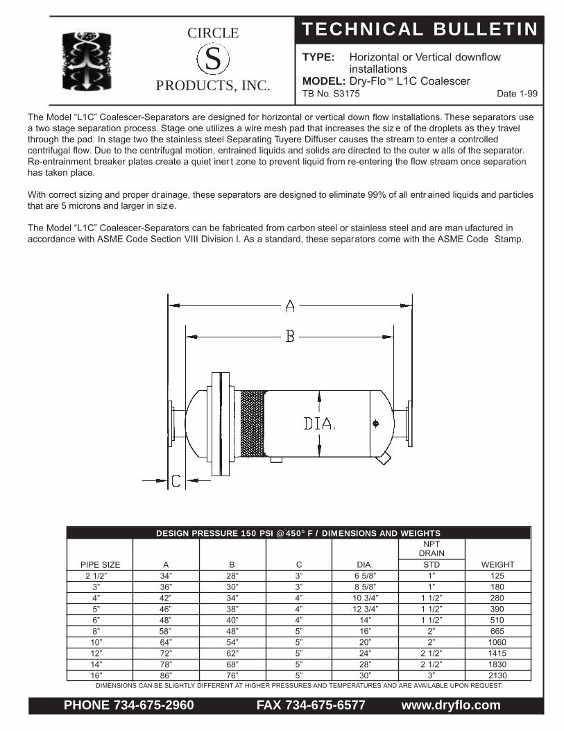
TYPE: Horizontal or Vertical downflowinstallations
MODEL: Dry-Flo™ L1C CoalescerTB No. S3175 Date 1-99
S
The Model “L1C” Coalescer-Separators are designed for horizontal or vertical down flow installations. These separators use a two stage separation process. Stage one utilizes a wire mesh pad that increases the siz e of the droplets as they travel through the pad. In stage two the stainless steel Separating Tuyere Diffuser causes the stream to enter a controlled centrifugal flow. Due to the centrifugal motion, entrained liquids and solids are directed to the outer w alls of the separator. Re-entrainment breaker plates create a quiet iner t zone to prevent liquid from re-entering the flow stream once separation has taken place.
With correct sizing and proper drainage, these separators are designed to eliminate 99% of all entr ained liquids and particlesthat are 5 microns and larger in siz e.
The Model “L1C” Coalescer-Separators can be fabricated from carbon steel or stainless steel and are man ufactured inaccordance with ASME Code Section VIII Division I. As a standard, these separators come with the ASME Code Stamp.
PIPE SIZE2 1/2”
3”4”5”6”8”10”12”14”16”
34”36”42”46”48”58”64”72”78”86”
28”30”34”38”40”48”54”62”68”76”
3”3”4”4”4”5”5”5”5”5”
6 5/8”8 5/8”
10 3/4”12 3/4”
14”16”20”24”28”30”
1”1”
1 1/2”1 1/2”1 1/2”
2”2”
2 1/2”2 1/2”
3”
125180280390510665
1060141518302130
A B C DIA. STD WEIGHT
DESIGN PRESSURE 150 PSI @ 450° F / DIMENSIONS AND WEIGHTSNPT
DRAIN
DIMENSIONS CAN BE SLIGHTLY DIFFERENT AT HIGHER PRESSURES AND TEMPERATURES AND ARE AVAILABLE UPON REQUEST.
CIRCLE
PRODUCTS, INC.
TECHNICAL BULLETIN
PHONE 734-675-2960 FAX 734-675-6577 www.dryflo.com
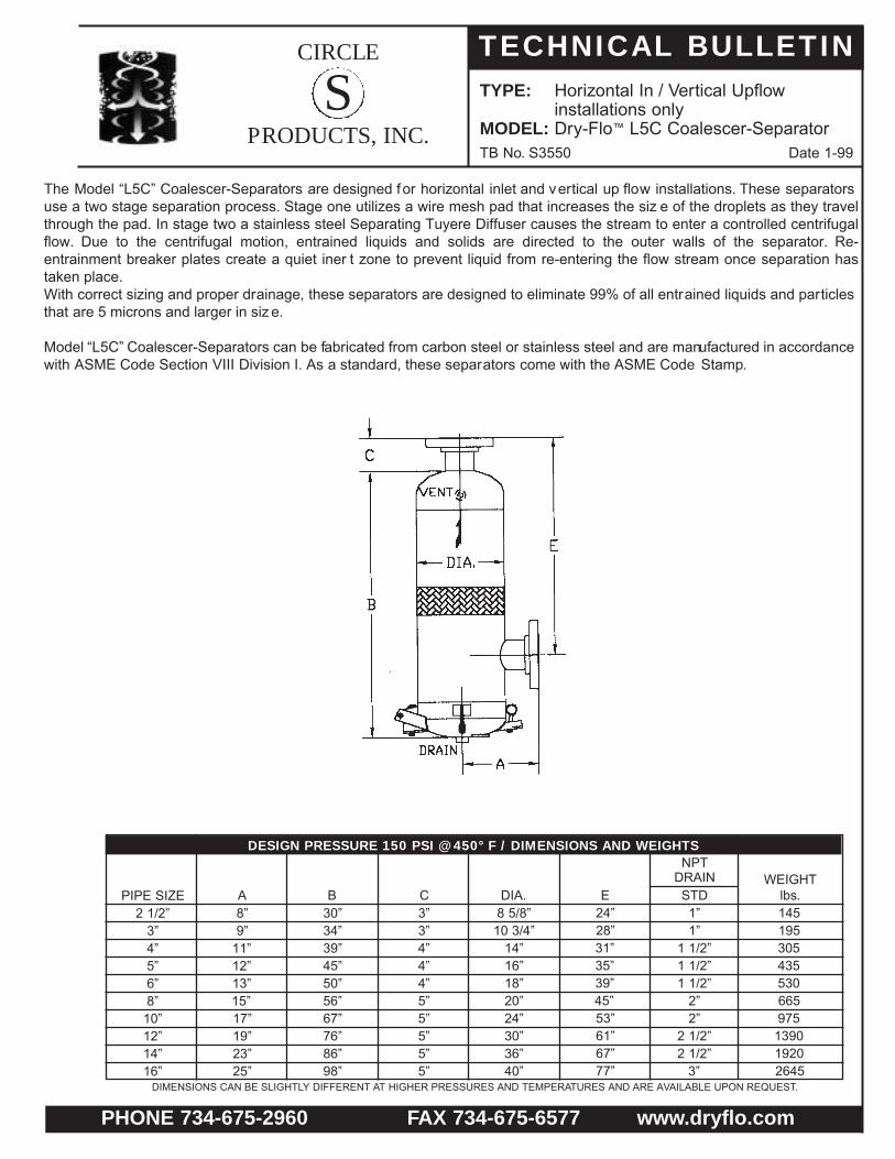
TYPE: Horizontal In / Vertical Upflowinstallations only
MODEL: Dry-Flo™ L5C Coalescer-SeparatorTB No. S3550 Date 1-99
S
The Model “L5C” Coalescer-Separators are designed for horizontal inlet and vertical up flow installations. These separators use a two stage separation process. Stage one utilizes a wire mesh pad that increases the siz e of the droplets as they travel through the pad. In stage two a stainless steel Separating Tuyere Diffuser causes the stream to enter a controlled centrifugal flow. Due to the centrifugal motion, entrained liquids and solids are directed to the outer walls of the separator. Re-entrainment breaker plates create a quiet iner t zone to prevent liquid from re-entering the flow stream once separation has taken place.With correct sizing and proper drainage, these separators are designed to eliminate 99% of all entrained liquids and particlesthat are 5 microns and larger in siz e.
Model “L5C” Coalescer-Separators can be fabricated from carbon steel or stainless steel and are manufactured in accordancewith ASME Code Section VIII Division I. As a standard, these separators come with the ASME Code Stamp.
PIPE SIZE2 1/2”
3”4”5”6”8”10”12”14”16”
8”9”
11”12”13”15”17”19”23”25”
30”34”39”45”50”56”67”76”86”98”
3”3”4”4”4”5”5”5”5”5”
8 5/8”10 3/4”
14”16”18”20”24”30”36”40”
1”1”
1 1/2”1 1/2”1 1/2”
2”2”
2 1/2”2 1/2”
3”
145195305435530665975
139019202645
A24”28”31”35”39”45”53”61”67”77”
EB C DIA. STDWEIGHT
lbs.
DESIGN PRESSURE 150 PSI @ 450° F / DIMENSIONS AND WEIGHTSNPT
DRAIN
DIMENSIONS CAN BE SLIGHTLY DIFFERENT AT HIGHER PRESSURES AND TEMPERATURES AND ARE AVAILABLE UPON REQUEST.

CIRCLE
PRODUCTS, INC.
TECHNICAL BULLETIN
PHONE 734-675-2960 FAX 734-675-6577 www.dryflo.com
TYPE: Horizontal In / Vertical downflowinstallations only
MODEL: Dry-Flo™ L6C Coalescer-SeparatorTB No. S3650 Date 1-99
S
The Model “L6C” Coalescer-Separators are designed for a horizontal inlet and and vertical up flow installations. These sepa-rators use a two stage separation process. Stage one utilizes a wire mesh pad that increases the size of the droplets as they travel through the pad. In stage two a stainless steel Separating Tuyere Diffuser causes the stream to enter a controlled cen-trifugal flow. Due to the centr ifugal motion, entrained liquids and solids are directed to the outer walls of the separator. Re-entrainment breaker plates create a quiet zone to prevent liquid from reenter ing the flow stream once separation has taken place.
With correct sizing and proper drainage, these separators are designed to eliminate 99% of all entrained liquids and particlesthat are 5 microns and larger in siz e.
Model “L6C” Coalescer-Separators can be fabricated from carbon steel or stainless steel and are manufactured in accordancewith ASME Code Section VIII Division I. As a standard, these separators come with the ASME Code Stamp.
PIPE SIZE2 1/2”
3”4”5”6”8”10”12”14”16”
7”8”
10”11”12”13”15”17”19”20”
37”41”44”51”54”66”77”88”96”101”
3”3”4”4”
10 3/4”12 3/4”
4”5”5”5”5”5”
6 5/8”8 5/8”
14”16”20”24”28”30”
1”1 1/2”1 1/2”1 1/2”1 1/2”
2”2”
2 1/2”2 1/2”
3”
130165295420475525590
112514751925
A30”33”36”41”42”53”60”70”77”80”
EB C DIA. STDWEIGHT
lbs.
DIMENSIONS AND WEIGHTSNPT
DRAIN
DIMENSIONS CAN BE SLIGHTLY DIFFERENT AT HIGHER PRESSURES AND TEMPERATURES AND ARE AVAILABLE UPON REQUEST.
CIRCLE
PRODUCTS, INC.
TECHNICAL BULLETIN
PHONE 734-675-2960 FAX 734-675-6577 www.dryflo.com
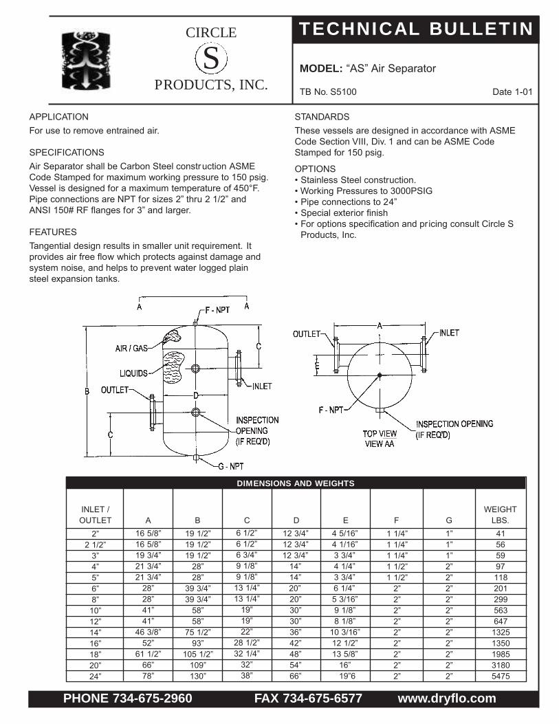
MODEL: “AS” Air Separator
TB No. S5100 Date 1-01
S
APPLICATIONFor use to remove entrained air.
SPECIFICATIONSAir Separator shall be Carbon Steel construction ASMECode Stamped for maximum working pressure to 150 psig.Vessel is designed for a maximum temperature of 450°F.Pipe connections are NPT for sizes 2” thru 2 1/2” andANSI 150# RF flanges for 3” and larger.
FEATURESTangential design results in smaller unit requirement. Itprovides air free flow which protects against damage andsystem noise, and helps to prevent water logged plainsteel expansion tanks.
STANDARDSThese vessels are designed in accordance with ASMECode Section VIII, Div. 1 and can be ASME CodeStamped for 150 psig.
OPTIONS• Stainless Steel construction.• Working Pressures to 3000PSIG• Pipe connections to 24”• Special exterior finish• For options specification and pr icing consult Circle S
Products, Inc.
INLET /OUTLET A B C D E F G
WEIGHTLBS.
2”2 1/2”
3”4”5”6”8”10”12”14”16”18”20”24”
12 3/4”12 3/4”12 3/4”
14”14”20”20”30”30”36”42”48”54”66”
4 5/16”4 1/16”3 3/4”4 1/4”3 3/4”6 1/4”5 3/16”9 1/8”8 1/8”
10 3/16”12 1/2”13 5/8”
16”19”6
6 1/2” 6 1/2” 6 3/4”9 1/8”9 1/8”
13 1/4”13 1/4”
19”19”22”
28 1/2”32 1/4”
32”38”
16 5/8”16 5/8”19 3/4”21 3/4”21 3/4”
28”28”41”41”
46 3/8”52”
61 1/2”66”78”
19 1/2”19 1/2”19 1/2”
28”28”
39 3/4”39 3/4”
58”58”
75 1/2”93”
105 1/2”109”130”
1 1/4”1 1/4”1 1/4”1 1/2”1 1/2”
2”2”2”2”2”2”2”2”2”
1”1”1”2”2”2”2”2”2”2”2”2”2”2”
41565997118201299563647
13251350198531805475
DIMENSIONS AND WEIGHTS