Embed Size (px)
Citation preview

Dry-cleaning of grapheneGerardo Algara-Siller, Ossi Lehtinen, Andrey Turchanin, and Ute Kaiser
Citation: Applied Physics Letters 104, 153115 (2014); doi: 10.1063/1.4871997 View online: http://dx.doi.org/10.1063/1.4871997 View Table of Contents: http://scitation.aip.org/content/aip/journal/apl/104/15?ver=pdfcov Published by the AIP Publishing Articles you may be interested in Self healing of defected graphene Appl. Phys. Lett. 102, 103107 (2013); 10.1063/1.4795292 Mechanical cleaning of graphene Appl. Phys. Lett. 100, 073110 (2012); 10.1063/1.3685504 The ripple's enhancement in graphene sheets by spark plasma sintering AIP Advances 1, 032170 (2011); 10.1063/1.3647307 Remote plasma assisted growth of graphene films Appl. Phys. Lett. 96, 154101 (2010); 10.1063/1.3387812 A direct transfer of layer-area graphene Appl. Phys. Lett. 96, 113102 (2010); 10.1063/1.3337091
This article is copyrighted as indicated in the article. Reuse of AIP content is subject to the terms at: http://scitation.aip.org/termsconditions. Downloaded to IP:
134.60.122.148 On: Fri, 13 Jun 2014 09:57:36
Dry-cleaning of graphene
Gerardo Algara-Siller,1,2 Ossi Lehtinen,1 Andrey Turchanin,3 and Ute Kaiser1,a)
1Central Facility for Electron Microscopy, Group of Electron Microscopy of Materials Science,Ulm University, Albert-Einstein-Allee 11, Ulm 89081, Germany2Department of Chemistry, Technical University Ilmenau, Weimarer Strasse 25, Ilmenau 98693, Germany3Faculty of Physics, University of Bielefeld, Universit€atsstr. 25, Bielefeld 33615, Germany
(Received 5 February 2014; accepted 9 April 2014; published online 17 April 2014)
Studies of the structural and electronic properties of graphene in its pristine state are hindered by
hydrocarbon contamination on the surfaces. Also, in many applications, contamination reduces the
performance of graphene. Contamination is introduced during sample preparation and is adsorbed
also directly from air. Here, we report on the development of a simple dry-cleaning method for
producing large atomically clean areas in free-standing graphene. The cleanness of graphene is
proven using aberration-corrected high-resolution transmission electron microscopy and electron
spectroscopy. VC 2014 AIP Publishing LLC. [http://dx.doi.org/10.1063/1.4871997]
Contamination build up on the surfaces of materials is a
prevalent problem in any application, where the surface
properties of the material are important. The consequences
of contamination are especially dire in the case of graphene
and other 2D-materials, which consist essentially only of
surfaces. The exceptional transport properties of graphene
are strongly influenced by residual impurities,1 the wettabil-
ity of graphene changes dramatically with adsorption of con-
tamination,2 and the performance of graphene based vapor
detectors depends on the cleanness of the surface,3 to name
only a few examples. Atomic-scale structural characteriza-
tion of graphene with aberration-corrected high-resolution
transmission electron microscopy (HRTEM) is strongly
hindered by contamination, as clean patches of only few to
tens of nanometers can be located in typical samples.
Consequently, the success of graphene as “the ultimate” sup-
porting film for studies of inorganic, organic, and biological
nano-objects is directly linked to the prerequisite of finding
efficient methods to clean it.4,5
Contamination is introduced on the surface of graphene
during sample preparation where, for example, the use of or-
ganic solvents and other liquids cannot typically be avoided.
Airborne pollutants landing on surfaces in ambient air is the
other main source of contamination. A measurable conse-
quence of the latter is the gradual increase of the mass of the
international standard kilogram.6 The surface contaminants
are typically composed of hydrocarbons with wide variation
in their stoichiometry (C¼O, C–OH, or H–C) and chain
lengths.7 Such contamination can be cross-linked and/or
graphitized under the electron beam of a transmission elec-
tron microscope (TEM)8 or at high temperatures.9,10
Heating treatment is a common practice for removing
hydrocarbon contamination from surfaces. Although anneal-
ing of graphene in vacuum or inert atmosphere reduces the
amount of contamination,11,12 it has been shown that resid-
uals are still present after such treatment.13,14
Recently, a different approach for cleaning graphene was
developed: The use of a metal catalyst to aid in the removal
of surface contamination15 on graphene. Longchamp et al.demonstrated that a metal-catalyst, i.e., Pt or Pd, removes
efficiently all contamination from graphene over large areas
(�0.2 lm2) at moderate temperatures (300 �C) and under
atmospheric conditions. However, depositing metals on the
sample surface is not always desirable, for instance if gra-
phene is to be used in electronic applications.
Here, we present a different graphene-cleaning
method—dry-cleaning with adsorbents—which is very sim-
ple and effective. By embedding free-standing single-layer
graphene supported on Quantifoil TEM grids in commonly
used adsorbents, such as activated carbon (Merck, “charcoal
activated for analysis”), and annealing the samples in moder-
ate temperatures, we observe surface cleanness of �95% in
single layer graphene, where cleanness is defined by the ratio
of contamination-free surface area to the total sample area.
For analyzing the cleanness of the samples, we employ
HRTEM using an aberration corrected FEI 80–300 TITAN
operated at 80 kV, and Auger electron spectroscopy (AES)
using a scanning electron microscope equipped with an elec-
tron energy analyzer (Multiscan Lab, Omicron). Further on,
we characterize the residual contamination after dry-
cleaning using electron energy-loss spectroscopy (EELS) in
the TEM (GIF Quantum energy filter). Where the typical
contamination on non-cleaned samples consists mainly of
hydrocarbons, the residual contamination after the dry-
cleaning procedure has a distinctly different character,
namely, aggregates with Si constitution.
The samples used were made of commercially available
graphene grown on Cu foil by chemical vapour deposition
(Graphenea S.A.) transferred to gold Quantifoil TEM-grids
(1.2 lm hole diameter) with a variation of the transfer
method reported by Pantelic et al.16 That is, in order to avoid
the use of polymethyl methacrylate, we transferred graphene
directly from the copper foil by contacting the TEM-grid to
graphene with isopropyl alcohol and afterwards etching
away the copper foil with ammonium peroxodisulfate. In the
case of dry-cleaning with activated carbon, the TEM-grid
with the transferred graphene was embedded in a powder of
activated carbon inside a glass vial. The vial was then placed
on a heating plate, which was heated from room temperature
a)Author to whom correspondence should be addressed. Electronic mail:
0003-6951/2014/104(15)/153115/4/$30.00 VC 2014 AIP Publishing LLC104, 153115-1
APPLIED PHYSICS LETTERS 104, 153115 (2014)
This article is copyrighted as indicated in the article. Reuse of AIP content is subject to the terms at: http://scitation.aip.org/termsconditions. Downloaded to IP:
134.60.122.148 On: Fri, 13 Jun 2014 09:57:36

to �210 �C at a rate of 5 �C/min. The sample was held at this
temperature for 30 min. Afterwards, the sample was let to
cool to room temperature and inserted in the TEM. To test
the dry-cleaning effect with two other adsorbents, i.e., acti-
vated alumina (Edwards) and molecular sieve 5A (Sigma
Aldrich), the adsorbents were first crushed in a mortar and
regenerated at a temperature of 300� for 30 min and cooled
down to �200 �C. Then the samples were embedded in the
adsorbent and allowed to clean for another 30 min. All the
samples were blown gently with air before inserting them in
the TEM to remove remaining adsorbent granulates from the
surface of the sample.
The cleaning effect of the dry-cleaning treatment with
activated carbon is exemplified in Figure 1. Panels (a) and
(b) show low and medium magnification HRTEM images of
a non-cleaned graphene sample. Here, the sample surface,
covered with contamination, has only small patches of clean
graphene with sizes ranging from nanometers to some tens
of nanometers and with only �6% of the sample surface free
of contamination. Such contamination coverage is typical of
non-cleaned graphene samples. It is worth noting that the
non-cleaned samples were produced no more than a week
before the experiment and stored in standard grid boxes. The
cleanness after dry-cleaning with activated carbon is consid-
erably improved, as shown in Figure 1, panels (c) and (d),
where the graphene cleanness rises to �95%, which can be
explained by the fact that activated carbon is a good adsorb-
ent for a broad range of organic impurities.17 The HRTEM
image in Figure 1(e) obtained from the boxed area in (d)
confirms that dry-cleaned graphene is, in fact, atomically
clean. Importantly, the graphene layer survives this treatment
even when it is free-standing over the holes of the Quantifoil
grid.
The effect of dry-cleaning with activated carbon was
characterized by AES with spatial resolution better than
100 nm using a primary electron beam at 3 keV and EELS in
the low energy-loss region. The AES data (Figure 2(a)) of
dry-cleaned graphene (blue line) and non-cleaned graphene
(red line) on Quantifoil grids were acquired under the same
experimental conditions, which allow their quantitative com-
parison. From these data, the intensity of the CKVV peak for
the non-cleaned graphene is observed to be �50% higher in
comparison to that for dry-cleaned graphene. Moreover, the
full-width at half maximum (FWHM) of the peak is also
higher for the non-cleaned sample (FWHM¼ 35 eV) in com-
parison to the dry-cleaned sample (FWHM¼ 27 eV). In
Figure 2(a), the AES spectrum for the Quantifoil film
FIG. 1. HRTEM images showing the effect of dry-cleaning of graphene
with activated carbon. (a) Low and (b) medium magnification images of
non-treated graphene. The sample surface is completely covered in contami-
nation, with only small clean patches from one nanometer to tens of nano-
meters in diameter. (c) Low and (d) medium magnification images of
graphene which has been dry-cleaned with activated carbon. The cleanness
of graphene obtained using activated carbon reaches 95%. (e) At high mag-
nification, the surface of graphene is observed to be atomically clean (aver-
age image over 10 frames).
FIG. 2. Characterization of the dry-cleaning effect and residual contamina-
tion. (a) AES spectra from Quantifoil film (black), free-standing non-cleaned
graphene (red), free-standing dry-cleaned graphene (blue), and vacuum refer-
ence (green). (b) Electron energy-loss spectrum of non-cleaned (red) and dry-
cleaned graphene (blue) in the low-loss region showing the intensity and shape
difference of the carbon p þ r excitation peak (�15 eV). (c) Background sub-
tracted (2nd order log polynomial) EEL spectrum (95–165 eV) of residual
contamination on dry-cleaned graphene. The shape and position of the peaks
are correlated to the Si-L2,3 ionization edge.21,22
153115-2 Algara-Siller et al. Appl. Phys. Lett. 104, 153115 (2014)
This article is copyrighted as indicated in the article. Reuse of AIP content is subject to the terms at: http://scitation.aip.org/termsconditions. Downloaded to IP:
134.60.122.148 On: Fri, 13 Jun 2014 09:57:36
consisting of �10–20 nm, of amorphous carbon is shown as
reference (black line). The intensity of the CKVV peak is
260% higher than that of dry-cleaned graphene with the
FWHM value of 48 eV. The lower intensity and the narrow
FWHM value of CKVV signal for the dry-cleaned graphene
clearly show the lower amount of carbon and its narrow
chemical variation. In the studied energy range, no other
Auger signals than the CKVV were identified in the graphene
samples. Carbonaceous contamination on graphene is
known18,19 to change the features of the plasmon p þ r(�15 eV) peak in EELS. The removal of carbonaceous con-
tamination is corroborated by the stark difference in the in-
tensity and shape of the plasmon peaks (Figure 2(b)) in our
EELS measurements (under same conditions) on non-
cleaned and dry-cleaned graphene (red line and blue line,
respectively). The intensity difference of the peaks is related
to the amount of carbon material which has been removed by
the cleaning method. Moreover, excitations at �10 eV and
20 eV in the non-cleaned graphene sample demonstrate the
presence of additional carbon species.20 This result is in
good agreement with the AES and HRTEM characteriza-
tions. Together, all these results unambiguously show the ef-
ficient removal of carbonaceous contamination from
graphene by activated carbon.
Nevertheless, some residual contamination is present on
the surface of graphene after the dry-cleaning treatment, seen
as dark long stripes in Figure 1(c), which qualitatively differs
from the typical carbonaceous contamination observed in a
non-cleaned sample. Therefore, the elemental composition of
this residual contamination was investigated by EELS (con-
vergence angle �1 mrad and collection angle 3.3 mrad). An
area of a dry-cleaned sample with residual contamination was
studied by scanning over an energy-loss range between 0 eV
and 600 eV. During scanning, we found a set of energy-loss
peaks between 95 eV and 165 eV, Figure 2(c). The prominent
peaks with energies around 105 eV and 108 eV energy-loss
are distinctive for the Si-L2,3 ionization edge of Si-containing
compounds.21,22 We speculate that the Si originates from the
TEM grid as X-ray photoelectron spectra of bare TEM grids
have shown that they contain traces of Si.
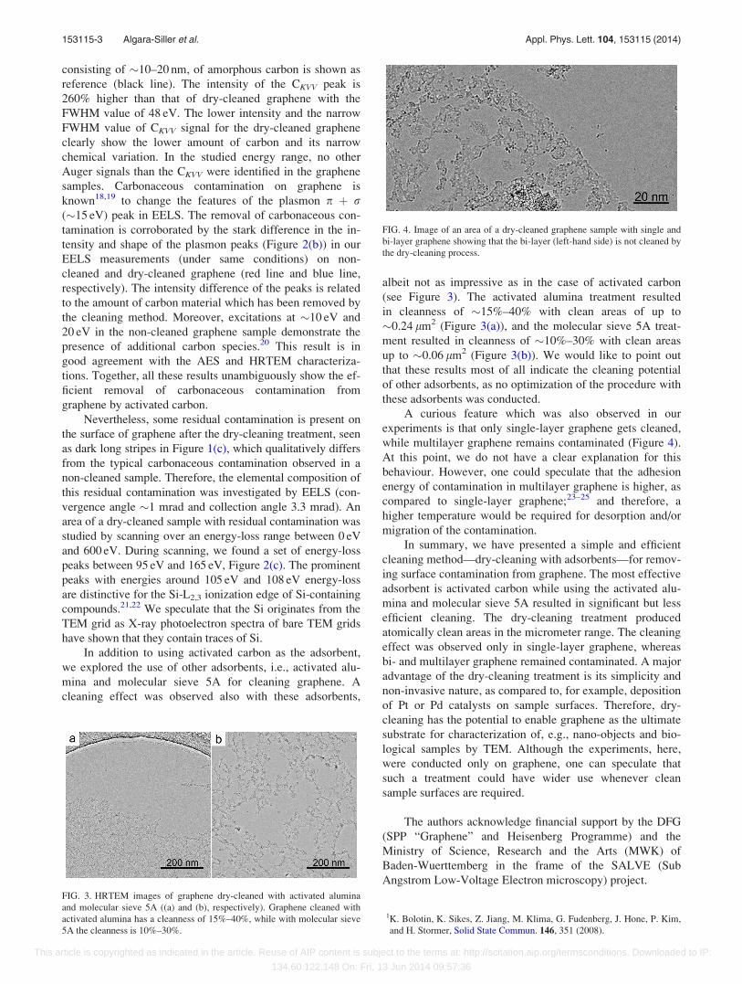
In addition to using activated carbon as the adsorbent,
we explored the use of other adsorbents, i.e., activated alu-
mina and molecular sieve 5A for cleaning graphene. A
cleaning effect was observed also with these adsorbents,
albeit not as impressive as in the case of activated carbon
(see Figure 3). The activated alumina treatment resulted
in cleanness of �15%–40% with clean areas of up to
�0.24 lm2 (Figure 3(a)), and the molecular sieve 5A treat-
ment resulted in cleanness of �10%–30% with clean areas
up to �0.06 lm2 (Figure 3(b)). We would like to point out
that these results most of all indicate the cleaning potential
of other adsorbents, as no optimization of the procedure with
these adsorbents was conducted.
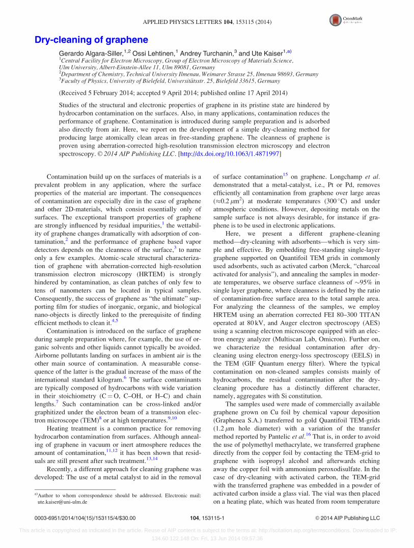
A curious feature which was also observed in our
experiments is that only single-layer graphene gets cleaned,
while multilayer graphene remains contaminated (Figure 4).
At this point, we do not have a clear explanation for this
behaviour. However, one could speculate that the adhesion
energy of contamination in multilayer graphene is higher, as
compared to single-layer graphene;23–25 and therefore, a
higher temperature would be required for desorption and/or
migration of the contamination.
In summary, we have presented a simple and efficient
cleaning method—dry-cleaning with adsorbents—for remov-
ing surface contamination from graphene. The most effective
adsorbent is activated carbon while using the activated alu-
mina and molecular sieve 5A resulted in significant but less
efficient cleaning. The dry-cleaning treatment produced
atomically clean areas in the micrometer range. The cleaning
effect was observed only in single-layer graphene, whereas
bi- and multilayer graphene remained contaminated. A major
advantage of the dry-cleaning treatment is its simplicity and
non-invasive nature, as compared to, for example, deposition
of Pt or Pd catalysts on sample surfaces. Therefore, dry-
cleaning has the potential to enable graphene as the ultimate
substrate for characterization of, e.g., nano-objects and bio-
logical samples by TEM. Although the experiments, here,
were conducted only on graphene, one can speculate that
such a treatment could have wider use whenever clean
sample surfaces are required.
The authors acknowledge financial support by the DFG
(SPP “Graphene” and Heisenberg Programme) and the
Ministry of Science, Research and the Arts (MWK) of
Baden-Wuerttemberg in the frame of the SALVE (Sub
Angstrom Low-Voltage Electron microscopy) project.
1K. Bolotin, K. Sikes, Z. Jiang, M. Klima, G. Fudenberg, J. Hone, P. Kim,
and H. Stormer, Solid State Commun. 146, 351 (2008).
FIG. 3. HRTEM images of graphene dry-cleaned with activated alumina
and molecular sieve 5A ((a) and (b), respectively). Graphene cleaned with
activated alumina has a cleanness of 15%–40%, while with molecular sieve
5A the cleanness is 10%–30%.
FIG. 4. Image of an area of a dry-cleaned graphene sample with single and
bi-layer graphene showing that the bi-layer (left-hand side) is not cleaned by
the dry-cleaning process.
153115-3 Algara-Siller et al. Appl. Phys. Lett. 104, 153115 (2014)
This article is copyrighted as indicated in the article. Reuse of AIP content is subject to the terms at: http://scitation.aip.org/termsconditions. Downloaded to IP:
134.60.122.148 On: Fri, 13 Jun 2014 09:57:36

2Z. Li, Y. Wang, A. Kozbial, G. Shenoy, F. Zhou, R. McGinley, P. Ireland,
B. Morganstein, A. Kunkel, S. P. Surwade, L. Li, and H. Liu, Nature
Mater. 12, 925 (2013).3Y. Dan, Y. Lu, N. J. Kybert, Z. Luo, and A. T. C. Johnson, Nano Lett. 9,
1472 (2009).4R. R. Nair, P. Blake, J. R. Blake, R. Zan, S. Anissimova, U. Bangert, A. P.
Golovanov, S. V. Morozov, A. K. Geim, K. S. Novoselov, and T.
Latychevskaia, Appl. Phys. Lett. 97, 153102 (2010).5R. S. Pantelic, J. C. Meyer, U. Kaiser, and H. Stahlberg, Solid State
Commun. 152, 1375 (2012).6P. J. Cumpson and M. Seah, Metrologia 33, 507 (1996).7S. Davidson, Measurement 40, 762 (2007).8J. C. Meyer, C. O. Girit, M. F. Crommie, and A. Zettl, Appl. Phys. Lett.
92, 123110 (2008).9B. Westenfelder, J. C. Meyer, J. Biskupek, S. Kurasch, F. Scholz, C. E.
Krill III, and U. Kaiser, Nano Lett. 11, 5123 (2011).10A. Barreiro, F. B€orrnert, S. M. Avdoshenko, B. Rellinghaus, G. Cuniberti,
M. H. R€ummeli, and L. M. K. Vandersypen, Sci. Rep. 3, 1115 (2013).11J. I. Paredes, S. Villar-Rodil, A. Mart�ınez-Alonso, and J. M. D. Tasc�on,
Langmuir 24, 10560 (2008).12J. Y. Mutus, L. Livadaru, J. T. Robinson, R. Urban, M. H. Salomons, M.
Cloutier, and R. A. Wolkow, New J. Phys. 13, 063011 (2011).13Z. Cheng, Q. Zhou, C. Wang, Q. Li, C. Wang, and Y. Fang, Nano Lett. 11,
767 (2011).
14Y.-C. Lin, C.-C. Lu, C.-H. Yeh, C. Jin, K. Suenaga, and P.-W. Chiu, Nano
Lett. 12, 414 (2012).15J.-N. Longchamp, C. Escher, and H.-W. Fink, J. Vac. Sci. Technol., B 31,
020605 (2013).16R. S. Pantelic, J. W. Suk, Y. Hao, R. S. Ruoff, and H. Stahlberg, Nano
Lett. 11, 4319 (2011).17R. C. Bansal, J.-B. Donnet, and F. Stoeckli, Active Carbon, 1st ed. (Marcel
Dekker, Inc., New York, USA, 1988).18T. Eberlein, U. Bangert, R. R. Nair, R. Jones, M. Gass, A. L. Bleloch, K.
S. Novoselov, A. Geim, and P. R. Briddon, Phys. Rev. B 77, 233406
(2008).19P. Wachsmuth, R. Hambach, M. K. Kinyanjui, M. Guzzo, G. Benner, and
U. Kaiser, Phys. Rev. B 88, 075433 (2013).20D. Rhinow, N.-E. Weber, and A. Turchanin, J. Phys. Chem. C 116, 12295
(2012).21O. Lichtenberger, J. Woltersdorf, N. Hering, and R. Riedel, Zeitschriff f€ur
Anorganische und Allgemeine Chemie 626, 1881 (2000).22K. Schulmeister and W. Mader, J. Non-Cryst. Solids 320, 143
(2003).23K. R. Paserba and A. J. Gellman, J. Chem. Phys. 115, 6737 (2001).24E. Londero, E. K. Karlson, M. Landahl, D. Ostrovskii, J. D. Rydberg, and
E. Schr€oder, J. Phys.: Condens. Matter 24, 424212 (2012).25C.-J. Shih, M. S. Strano, and D. Blankschtein, Nature Mater. 12, 866
(2013).
153115-4 Algara-Siller et al. Appl. Phys. Lett. 104, 153115 (2014)
This article is copyrighted as indicated in the article. Reuse of AIP content is subject to the terms at: http://scitation.aip.org/termsconditions. Downloaded to IP:
134.60.122.148 On: Fri, 13 Jun 2014 09:57:36


![Theelectronicproperties of bilayer graphene · graphene [40], twisted graphene [41–46] or two graphene sheets separated by a dielectric with, possibly, electronic interactions between](https://img.dokumen.tips/doc/110x75/5e69aa2b87c67d520529bd33/theelectronicproperties-of-bilayer-graphene-graphene-40-twisted-graphene-41a46.jpg)