Embed Size (px)
Citation preview

DroC2om - 763601 - D4.1 Cellular LTE/5G system concepts to provide optimal support for both terrestrial communications and high reliability UAS data links
DeliverableID [D4.1]
ProjectAcronym DroC2om
Grant: 763601 Call: H2020-SESAR-2016-1 Topic: RPAS-05 DataLink Consortium coordinator: AAU Edition date: [28 May 2018] Edition: [01.00] Template Edition: 02.00.00
EXPLORATORY RESEARCH

EDITION [01.00]
2
Authoring & Approval
Authors of the document
Name/Beneficiary Position/Title Date
István Z. Kovács WP4 lead 30/05/2018
Jeroen Wigard Project TM 30/05/2018
Nicolas Van Wambeke WP2 lead 30/05/2018
Rafhael Amorim Contributor 30/05/2018
Reviewers internal to the project
Name/Beneficiary Position/Title Date
Ulrich Tuerke / atesio WP3 lead 01/05/2018
Matthieu Clergeaud / Thales Contributor 01/05/2018
Approved for submission to the SJU By - Representatives of beneficiaries involved in the project
Name/Beneficiary Position/Title Date
Troels B. Sørensen Project Coordinator / AAU 29/05/2018
Rejected By - Representatives of beneficiaries involved in the project
Name/Beneficiary Position/Title Date

DROC2OM - 763601 - D4.1 Cellular LTE/5G system concepts to provide optimal support for both terrestrial communications and high reliability UAS data links
3
Document History
Edition Date Status Author Justification
00.10 08/11/2017 DRAFT István Z. K. Slide material moved to D4.1 template; Early ToC
00.20 31/01/2018 DRAFT István Z. K. Add first references, abbreviations, terms. Updated ToC.
00.3x 06/03/2018 DRAFT István Z. K. Start adding content in the LTE/5G architecture sections and evaluation sections
00.40 12/04/2018 DRAFT István Z. K. Re-structure the evaluation and experimental mobility results sections. Add first set of 3GPP results.
00.5x 25/04/2018 DRAFT István Z. K.
Jeroen W.
Finalise reference 3GPP and site-specific results section. Move 3GPP results to Annex. Add first results with proposed solutions.
00.6x 30/04/2018 DRAFT István Z. K.
Jeroen W.
Add preliminary Abstract and Summary. Write section on link to WP3.
First input to the hybrid access section (moved to Section 2)
00.70 01/05/2018 DRAFT István Z. K.
Jeroen W.
Distributed for internal DroC2om review.
01.00 28/05/2018 Final István Z. K. Incorporate reviewer’s comments and suggestions.
Dissemination level: Public
Copyright Statement:
© – 2018 – Thales Alenia Space, Aalborg University, Nokia Bell Labs, atesio GmbH.
All rights reserved. Licensed to the SESAR Joint Undertaking under conditions.

EDITION [01.00]
4
DroC2om DRONE CRITICAL COMMUNICATIONS
This technical deliverable is part of a project that has received funding from the SESAR Joint Undertaking under grant agreement No 763601 under European Union’s Horizon 2020 research and innovation programme
1.
Abstract
In this Deliverable D4.1 we have provided an extensive analysis of 3GPP LTE terrestrial/cellular network support of UAS DataLink communications. The radio access and radio mobility mechanisms with direct impact on the performance of the UAS DataLink service have been described and evaluated. The UAS DataLink traffic model in these first evaluations was selected to be the 3GPP C2 model, which from radio access point of view requires: 99.9 % reliability within a 50 ms delay budget for transmissions of 1250 Bytes packets every 100 ms. The radio evaluation models and methodology are a direct outcome of the radio measurement and experiments documented in Deliverable D5.1.
First, the radio network architecture for 3GPP LTE and 5G NR have been introduced, highlighting the main elements which are to play a key role in the terrestrial cellular network support for DataLink and later also in the integrated hybrid cellular-satellite DataLink solutions. In this Deliverable D4.1 we also started to sketch the first elements of the possible integrated hybrid cellular-satellite DataLink solutions. This activity was mostly based on the state-of-the-art hybrid access techniques specified in the Broadband Forum and a priori knowledge on some of the UAS multilink concepts developed in previous research projects.
Due to its modular principles, flexible configurations, and converged core approach, the 5G NR architecture is recommended as baseline for future UAS DataLink communications studies within DroC2om and other similar research projects.
Next, we have analysed the baseline radio access and radio mobility performance in typical LTE network deployments, when providing the Command and Control (C2) DataLink service to UAVs. These reference studies have been carried out via numerical simulations in site-specific, rural and urban LTE network scenarios (Fyn and Aalborg, Denmark). Furthermore, in all simulations, also the
1 The opinions expressed herein reflect the author’s view only. Under no circumstances shall the SESAR Joint
Undertaking be responsible for any use that may be made of the information contained herein.

DROC2OM - 763601 - D4.1 Cellular LTE/5G system concepts to provide optimal support for both terrestrial communications and high reliability UAS data links
5
usual terrestrial users have been taken in consideration and their performance analysed. The results clearly indicate that even in both rural and urban scenarios the downlink network traffic load, which is mostly generated by terrestrial users, is a dominant factor in the performance of the UAS DataLink services. Conversely, the UAS DataLink service can significantly degrade the uplink performance of all users in the network. Under the 3GPP C2 traffic profile, the 99.9 % reliability requirement was shown as being impossible to meet at higher UAV heights higher than 15-20 m, even with very low spatial density of UAVs and in low network traffic load conditions. This result indicates that the Droc2om ‘high’ traffic profile requirements will be even more challenging to meet in practice. However, for Droc2om ‘low’ traffic profile the performances are expected to improve significantly and current LTE networks might be able to provide the communication link for UAS DataLink services.
The first experimental results on radio mobility, performed in Urban Aalborg using connectivity provided by two different NMOs (live LTE networks), have been analysed. Like in simulations, these measurements also highlighted the difficulties in providing the 99.9 % reliability level when connected to an LTE network. However, when a dual-LTE connectivity can be used – where the UAV radio modem is always connected to the network with best performance – our theoretical analysis shows that the 3GPP C2 traffic profile requirements could be met. Our recommendation, and plan in Workpackage 4, is to follow up on this study based on more extensive investigations to be carried out in Workpackage 5, and to develop a dual-LTE connectivity framework specifically tailored for UAS DataLink services.
The third part of the work focused on the evaluation of downlink and uplink radio interference mitigation mechanisms required to meet the 3GPP C2 traffic profile requirements, in both rural and urban scenarios. Techniques for both user terminal and network side have been explored. The main findings show that UAVs equipped with more advanced LTE modems, including interference cancelling receiver and/or transmit/receive beam switching capabilities, can significantly boost the UAS DataLink performance.
We recommend therefore the use of these advanced LTE modems for highly reliable UAS DataLink services. On the network side, several improvements can also be implemented, especially in the area of interference coordination among the radio cells and carrier frequency re-use for UAS DataLink services. Nevertheless, these network upgrades might prove quite costly – in both hardware/software cost and terrestrial subscribers’ radio service performance – for certain MNOs, at least in regions where the density of the expected UAV subscribers is very low. Therefore, we recommend the network upgrades to be introduced in networks where there is high UAV traffic – high revenue for MNO – or when features are needed also for terrestrial user services, e.g. inter-cell interference coordination in dense urban area.
In conclusion, the Deliverable D4.1 has addressed, from terrestrial (cellular) radio access point of view, most of the general requirements as outlined in Deliverable D2.1. Several requirements remain to be addressed in upcoming work, in the context of Deliverable D4.3 and in the conjunction with the Workpackage 3 activities.

EDITION [01.00]
6
Table of Contents
1 Introduction ............................................................................................................... 9
2 Cellular radio networks ............................................................................................ 16
3 DataLink performance evaluation ............................................................................ 25
4 Cellular radio mechanisms for DataLink provisioning ................................................ 47
5 Conclusions and recommendations ........................................................................... 55
6 References ............................................................................................................... 62
Appendix A State-of-the-art cellular radio access – Uu interfaces ............................... 65
Appendix B Performance evaluations in 3GPP Aerial Vehicle scenarios....................... 67

DROC2OM - 763601 - D4.1 Cellular LTE/5G system concepts to provide optimal support for both terrestrial communications and high reliability UAS data links
7
List of Tables Table 1: Abbreviations ........................................................................................................................... 14
Table 2: Terminology and definitions .................................................................................................... 15
Table 3: Mobility simulation assumptions for site-specific Rural Fyn [20] and Urban Aalborg scenarios. ............................................................................................................................................................... 28
Table 4: Preliminary content of the cellular radio data time traces provided by Workpackage 3 for cellular radio access performance simulations in Workpackage 4. ...................................................... 45
Table 5: Preliminary content of the terrestrial-only radio access performance data time traces provided by Workpackage 4 for performance visualisation in Workpackage 3. .................................. 46
Table 6: General user performance requirements................................................................................ 57
Table 7: Generic user functional requirements. ................................................................................... 58
Table 8: Generic data link functional requirements. ............................................................................. 58
Table 9: Terrestrial C2 link specific requirements. ................................................................................ 59
Table 10: Requirements to support Multiple Operator. ....................................................................... 60
List of Figures Figure 1: Combined cellular-satellite radio network architecture concept (based on [1]). The scope of Deliverable D4.1 is highlighted. ............................................................................................................... 9
Figure 2: The 3GPP EPS elements, functions and interfaces. The functional split between E-UTRAN and EPC (core network) is also indicated. ............................................................................................. 16
Figure 3: The 3GPP 5G system architecture (non-roaming, reference point representation). ............ 19
Figure 4: The 3GPP E-UTRAN architecture. ........................................................................................... 20
Figure 5: The 3GPP NG-RAN architecture (standalone deployment). ................................................... 22
Figure 6: High level block diagram of the hybrid cellular-satellite DataLink solution targeted in DroC2om. .............................................................................................................................................. 24
Figure 7: The site-specific Rural Fyn (top) and Urban Aalborg (bottom) radio network deployment layouts. Radio site locations and sector (cell) orientations are depicted. ............................................ 27
Figure 8: Baseline radio performance of Aerial Vehicles in the Rural Fyn scenario. ............................ 30
Figure 9: Baseline radio mobility performance of Aerial Vehicles in the Rural Fyn scenario for two network load points (30 % for medium load 67 % for high load). ........................................................ 31
Figure 10: Baseline radio performance of Terrestrial UEs in the Rural Fyn scenario for two network load points (30 % for medium load 67 % for high load). The left most bars in each plot correspond to the scenarios without AVs, i.e. with only Terrestrial UEs. .................................................................... 32

EDITION [01.00]
8
Figure 11: Baseline radio mobility performance of Aerial Vehicles in the Urban Aalborg scenario for two network load points (30 % for medium load 57 % for high load) and 1 % UAV penetration ratio.35
Figure 12: Baseline radio mobility performance of Aerial Vehicles in the Urban Aalborg scenario for medium network load (30 %) and 1 % or 10 % UAV penetration ratio. ............................................... 36
Figure 13: Baseline radio performance of Terrestrial UEs in the Urban Aalborg scenario for two network load points (30 % for medium load 57 % for high load) and 1 % UAV penetration ratio. The left most bars in each plot correspond to the scenarios without AVs, i.e. with only Terrestrial UEs. . 37
Figure 14: Baseline radio performance of Terrestrial UEs in the Urban Aalborg scenario for medium network load points (30 %) and 1 % or 10 % UAV penetration ratio. The left most bars in each plot correspond to the scenarios without AVs, i.e. with only Terrestrial UEs. ............................................. 38
Figure 15: UAV flight route at 40 m height, and radio hand-over events for test UE connected to Network 1. Only the Network 1 radio cells are depicted. ..................................................................... 43
Figure 16: UAV flight route at 40 m height (same as in Figure 15), and radio hand-over events for test UE connected to Network 2. Only the Network 2 radio cells are depicted. ......................................... 43
Figure 17: The RSRP, RSRQ and downlink packet delay KPIs recorded during the UAV flight at 40 m height. The separate results in Network 1 (blue) and Network 2 (red) depicted. The radio hand-over events, separately within each Network, are marked with green triangles. ........................................ 44
Figure 18: The radio access outage levels achievable in the two separate Networks and with a theoretical dual-LTE radio access scheme, during the UAV flight at 40 m height depicted in Figure 15 and Figure 16, and based on the analysis of the KPIs shown in Figure 17. ........................................... 44
Figure 19: Antenna beam steering configurations for the drone with 2, 4 and 6 fixed beams ............ 47
Figure 20: Outage probability for a drone at 120 m in urban environments with and without fixed grid of beams for the medium and high network load case. ................................................................ 48
Figure 21: Outage probability for a drone at 120 m in urban environments with and without interference cancellation, removing the 3 potential strongest interferers completely for the medium and high network load case. ................................................................................................................. 49
Figure 22: Outage probability for a drone at 120 m in urban environments with and without ICIC with 10 and 20 cells muted for the medium and high network load case. ................................................... 50
Figure 23: Network beam steering concept for UAVs. ......................................................................... 50
Figure 24: Uplink throughput for UAV (left axis) and terrestrial (right axis) users for different UAV-specific power P0 settings for the medium network load case with 1% of the users being UAVs. ...... 51
Figure 25: Uplink throughput for UAV (left axis) and terrestrial (right axis) users for different number of beams from the UAV for the medium network load case with 1% of the users being UAVs ........... 52

DROC2OM - 763601 - D4.1 Cellular LTE/5G system concepts to provide optimal support for both terrestrial communications and high reliability UAS data links
9
1 Introduction
1.1 Purpose and Scope
The target of this Deliverable is to provide 3GPP cellular 4G/5G radio concepts and radio performance evaluations for solutions supporting UAS data link connectivity. The overall framework of Workpackage 4 activities is depicted in Figure 1 (based on [1]) with the scope of Deliverable D4.1 highlighted.
The work has been carried out in close collaboration and with input from Workpackage 2 and Workpackage 5 activites. The system requirements and scenarios detailed in Deliverable D2.1 [2] have been used whenever possible. The propagation models derived based on the experimental work described in Deliverable D5.1 [3] have been incorporated in the simulation tool used for the performance evaluations.
Figure 1: Combined cellular-satellite radio network architecture concept (based on [1]). The scope of Deliverable D4.1 is highlighted.
Scope of D4.1
U-plane Mgmt
Radio mobility Radio mobility
Integrated data link – Hybrid C/U-plane management
U-plane Mgmt
Radio adaptation
Radio adaptation
UAV
3GPP RAN
SAT RA
SGW

EDITION [01.00]
10
1.2 Technical contributions
The work documented in this Deliverable D4.1 has contributed to the following technical DroC2om areas:
o 3GPP LTE and 5G radio access network concepts for UAS data link provisioning – Section 2. o Methodology and extensive LTE radio access and mobility performance evaluation result
for UAS data link provisioning, with in-depth analysis of potential solutions – Section 3.1, Section 3.2 and Section 4.1.
o Preliminary analysis of first radio mobility measurements in live LTE networks – Section 3.3. o First proposals for the integrated (hybrid) SAT-3GPP LTE radio architecture – Section 2.3.

DROC2OM - 763601 - D4.1 Cellular LTE/5G system concepts to provide optimal support for both terrestrial communications and high reliability UAS data links
11
1.3 Abbreviations, terminology and definitions
Abbreviation Explanation
3G 3GPP UMTS 3rd
generation cellular systems
3GPP 3rd
Generation Partnership Project (cellular systems)
4G 3GPP UMTS-LTE (E-UTRAN) 4th
generation cellular systems (aka LTE)
5G 3GPP 5th
generation cellular systems
5GC 3GPP 5G Core Network
5G NR 3GPP 5th
generation New Radio cellular systems
AERO Asymmetric Extended Route Optimization
AF Application Function (5G)
AFRMS Airborne Flight and Radio Management System
AMF Access and Mobility Management Function (5G)
ANS Air Navigation Services
AS Access Stratum (communication protocol)
ATM Air Traffic Management (manned and unmanned)
ATS Air Traffic Services
AUSF Authentication Server Function (5G)
AV Aerial Vehicle(3GPP) or Drone (SJU)
BBF Broadband Forum
BVLOS Beyond Visual Line-Of-Sight
C2 (C&C) Command and Control
CN Core Network (3GPP)
CM Connection Management
EASA European Aviation Safety Agency
D&A (DAA) Detect and Avoid
DL Downlink radio communication, Forward link (FWD): Network/Satellite -to- UA
DN Data Network e.g. operator services, Internet access or 3rd party services
DTM Drone Traffic Management
eNodeB (eNB) E-UTRAN Node B (base station)
gNB 5G Node B
HCPE Hybrid-access Consumer Premises Equipment
HAG Hybrid-access Gateway
HDLGW Hybrid (multilink) DataLink Gateway. Same as Multi-Link Gateway (MLGW)
HDLUE Hybrid (multilink) DataLink User Equipment. Same as Multi-Link Adaptor (MLA)

EDITION [01.00]
12
ICAO International Civil Aviation Organization
IP Internet Protocol
IPv4 IP version 4
IPv6 IP version 6
JARUS Joint Authorities for Rulemaking of Unmanned Systems
KPI Key Performance Indicator
L2 Layer 2 communication protocols
LA Link adaptation (radio)
LISP A Multi-Homing and Mobility Solutions for ATN using IPv6
LOS Radio Line-Of-Sight
LTE 3GPP UMTS Long Term Evolution (Release 8-9)
LTE-A, LTE-Advanced 3GPP UMTS Long Term Evolution Advanced (Release 10-15)
GBR Guaranteed Bit Rate
gNodeB (gNB) Next generation NodeB (5G)
gNB-CU gNB Central Unit
gNB-DU gNB Distributed Unit
GRE Generic Routing Encapsulation
HA Hybrid Access (BBF)
HAG Hybrid Access Gateway. A logical function in the operator network implementing the network side mechanisms for simultaneous use of both e.g. SAT and 3GPP access networks
HCPE Hybrid Customer Premises Equipment (CPE). CPE enhanced to support the access side mechanisms for simultaneous use of both e.g. SAT and 3GPP access
HO Radio hand-over (serving cell change)
IETF Internet Engineering Task Force
MAC Medium Access Control layer (communication protocol)
MLA MultiLink Adaptor
MLGW MultiLink Gateway
MME Mobility Management Entity (4G)
MPTCP Multipath TCP
NAS Non-access Stratum (communication protocol)
N3IWF Non-3GPP InterWorking Function (5G)
NEF Network Exposure Function (5G)
NG Next Generation (5G)
NLOS Radio Non-Line-Of-Sight
NRF NF Repository Function (5G)

DROC2OM - 763601 - D4.1 Cellular LTE/5G system concepts to provide optimal support for both terrestrial communications and high reliability UAS data links
13
NSSF Network Slice Selection Function (5G)
OWD One-way delay
PCF Policy Control Function (5G)
PDCP Packet Data Convergence Protocol (communication protocol, 3GPP)
P-GW Packet Data Network Gateway (4G)
PHY Physical layer (communication protocol)
PiC Pilot in Command
QCI QoS Class Identifier
QoS Quality of Service
Qout (DL) Serving Signal Quality Outage
QUIC Quick UPD Internet Connections
RAN Radio Access Network
RLC Radio Link Control layer (communication protocol)
RLF Radio Link Failure
RMa Rural Macro (3GPP scenario)
RTT Round Trip Time
RPAS Remotely Piloted Aircraft System: Equivalent to UAS
RRC Radio Resource Control layer (communication protocol)
RRM Radio Resource Management
SAT Satellite System/Network
S(at)GW Satellite Gateway
SATPL Satellite Transparent payload (supported by Platform)
SEPP Security Edge Protection Proxy (5G)
SDAP Service Data Adaptation Protocol (5G)
SESAR JU Single European Sky Air traffic management Research Joint Undertaking
SFRMS Satellite Flight and Radio Management System
S-GW Serving Gateway (4G)
SoA State-Of-the-Art (literature, solution, concept)
SMF Session Management Function (5G)
TCP Transmission Control Protocol
TR Technical Report
UA Unmanned Aerial/Aircraft
UAS Unmanned Aerial/Aircraft System, including UAV, ground control, and communication link
UDM Unified Data Management (5G)

EDITION [01.00]
14
UDP User Datagram Protocol
UDR Unified Data Repository (5G)
UDSF Unstructured Data Storage Function (5G)
UE User Equipment (3GPP 4G/5G)
UL Uplink radio communication, Reverse link: UA -to- Network/Satellite
UMa Urban Macro (3GPP scenario)
UPF User Plane Function (5G)
U-Space See Table 2
VLOS Visual Line-Of-Sight
VPN Virtual Private Network
Table 1: Abbreviations
Term Explanation
C2, C2 DataLink, UAS DataLink
“Command and Control” Link, a data link established between the remote “Pilot in Command” (PiC) and the vehicle it is controlling. This link is used to exchange data necessary for the Aviate, Navigate, Communicate functions of the airborne platform and is different from the “Payload Communication” link that is used to carry data related to the mission of the vehicle from a customer point of view.
C-plane Control plane radio communication protocols; control messages, data packets used to manage the user plane (U-plane)
Drone UAV with private or commercial application, operating in the EASA Open or Specific category.
Hybrid Access The coordinated and simultaneous use of two heterogeneous access paths (e.g., LTE and SAT).
Hybrid Access path Network connectivity instance between HCPE and HAG over a given access network; SAT or 3GPP.
Hybrid Access session
A logical construct that represents the aggregate of network connectivity for a Hybrid Access subscriber at the HAG. It represents all traffic associated with a subscriber by a given service provider, with the exception of Hybrid Access bypass traffic, and provides a context for policy enforcement.
Payload The term payload designates the equipment that is hosted on a physical aerial/airborne platform for the purpose of performing the mission.
The term payload can be used in reference to a UAV Payload (i.e. the equipment on board the UAV that are used for the UAV to perform its mission, e.g. sensors or cameras used to examine a given geographical area).
The term payload can be used in reference to a Satellite Payload (i.e. the equipment on board a satellite that is used for the satellite to perform its mission, e.g. a transparent signal repeater in a telecommunication satellite or an optical equipment in an earth observation satellite).
Radio adaptation Adaptation and configuration mechanisms on the PHYsical layer and Medium Access Control layer
Radio capacity The transmission (DL and UL) radio resources available in the radio system.

DROC2OM - 763601 - D4.1 Cellular LTE/5G system concepts to provide optimal support for both terrestrial communications and high reliability UAS data links
15
Radio link The DL or UL radio transmission link
Radio mobility UE changing the serving radio cell (base station, eNB, satellite) due to physical movement, radio channel changes, or explicit commands from the serving cell.
U-plane User plane radio communication protocols; payload end-user data packets
U-Space A set of new services and specific procedures designed to support safe, efficient and secure access to airspace for large number of drones.
Table 2: Terminology and definitions

EDITION [01.00]
16
2 Cellular radio networks
In this section we provide a summary of the network architecture elements for LTE/4G and 5G NR which are considered relevant for the final UAS DataLink provisioning solutions targeted in the DroC2om project (Deliverable D4.3). The following description of the state-of-the art is not meant to be exhaustive, or a tutorial like description; and all the technical details can be found in the corresponding 3GPP specification documents.
2.1 State-of-the-art cellular system architecture
2.1.1 LTE/4G: Evolved Packet System
The evolution of the non-radio functionalities known under the term “System Architecture Evolution” (SAE), which includes the Evolved Packet Core (EPC) network, together with the Evolved UTRAN (E-UTRAN) access network, comprise the Evolved Packet System (EPS).
The EPS uses the concept of end-to-end EPS bearers to route IP traffic from a gateway in the packet data network (PDN) to the user equipment (UE). An end-to-end bearer is an IP packet flow with a defined quality of service (QoS) between the gateway and the UE. The E-UTRAN and EPC together manage (set up and release) the end-to-end bearers as required by the different UE applications. The PDN gateway provides Internet access (IP connectivity) to each UE.
The various elements, functions and interfaces in the EPS are depicted in
Figure 2. A more detailed description of the EPS can be found in [4] [5].
Figure 2: The 3GPP EPS elements, functions and interfaces. The functional split between E-UTRAN and EPC (core network) is also indicated.
For the purpose of the DataLink provisioning as addressed in DroC2om, here we focus the discussions on a few EPS elements only: serving gateway (S-GW), packet data gateway (P-GW) and mobility management entity (MME). While the policy control and charging rules function (PCRF) and the home subscriber server (HSS) are also needed, their functionality might not need to be adapted in order to support DataLink services.
UE eNodeB S-GW P-GW
MME
HSS
PCRF
LTE-Uu S1-U
S1-MME S11
S5/S8
S6a
Gx
Rx
SGi
E-URAN EPC
DN

DROC2OM - 763601 - D4.1 Cellular LTE/5G system concepts to provide optimal support for both terrestrial communications and high reliability UAS data links
17
We list below the potential relationship between these entities and the DataLink service. More details will likely be identified in the final DroC2om hybrid access architecture proposal(s) to be documented in Deliverable D4.3.
P-GW: “P-GW – The PDN Gateway is responsible for IP address allocation for the UE, as well as QoS enforcement and flow-based charging according to rules from the PCRF. It is responsible for the filtering of downlink user IP packets into the different QoS-based bearers. This is performed based on Traffic Flow Templates (TFTs). The P-GW performs QoS enforcement for guaranteed bit rate (GBR) bearers. It also serves as the mobility anchor for interworking with non-3GPP technologies [...].” [4]
o Managing (address allocation, address translation, and QoS enforcement) of the DataLink packets flows to/from outside the Operator’s network.
o Ideally the P-GW should have enough knowledge on the DataLink traffic type and requirements in order to be able to properly manage the QoS. This information can be provided by the PCRF by means of QoS authorization (QoS class and bitrates).
o The P-GW (possibly complemented with required U-Space specific functionalities) will be the main DataLink interface entity to the U-Space and the UAS Connectivity Service Provider.
S-GW: “S-GW – All user IP packets are transferred through the Serving Gateway, which serves as the local mobility anchor for the data bearers when the UE moves between eNodeBs. It also retains the information about the bearers when the UE is in the idle state (known as “EPS Connection Management — IDLE” [ECM-IDLE]) and temporarily buffers downlink data while the MME initiates paging of the UE to reestablish the bearers.” [4]
o Maintaining the high availability of the end-to-end data bearer carrying the DataLink packets.
o When multiple eNodeB would be used simultaneously (multi-connectivity) to provide the DataLink the S-GW has the role of coordinating them, in addition to the direct inter-eNodeB coordination (via X2).
MME: “MME – The Mobility Management Entity (MME) is the control node that processes the signalling between the UE and the CN. The protocols running between the UE and the CN are known as the Non- Access Stratum (NAS) protocols.” [4]
o Establishment, maintenance and release of the bearer carrying the DataLink packets o Security and authentication functionalities, mobility in the NAS layer
Interworking with non-3GPP access
The EPS supports the use of non-3GPP IP access networks to access the EPC, such as WLAN or WiMax [5]. The EPS architecture presented in
Figure 2 does not show the interworking with non-3GPP IP access. In order to realize the hybrid cellular-satellite access for the DataLink service, the EPC needs to be interfaced (gateway -based or application -based) with the satellite access network, ideally using one of the interworking options already defined in 3GPP [5]. The DroC2om proposal for this will be detailed in the in Deliverable D4.3.

EDITION [01.00]
18
2.1.2 5G: System architecture
One representation of the current 5G System Architecture is depicted in Figure 3 [6]. Like the presentation in Section 2.1.1, here we discuss only the entities and functionalities most relevant to the DroC2om studies for UAS DataLink provisioning.
AMF: Access and Mobility Management function includes the following main functionalities: o Termination of RAN CP interface (N2). o Termination of NAS (N1), NAS ciphering and integrity protection. o Registration, Connection, Reachability and Mobility management. o Access Authentication and Authorization. o Support of N2 interface with Non-3GPP InterWorking Function (N3IWF) and NAS
signalling with an UE over N3IWF. o Management of mobility, authentication, and separate security context state(s) of a UE
connected via non-3GPP access or connected via 3GPP and non-3GPP accesses simultaneously [7].
SMF: Session Management function includes the following main functionalities: o Session Management, e.g. Session establishment, modify and release, including tunnel
maintain between UPF and AN node. o UE IP address allocation & management (including optional Authorization). o Selection and control of UP function, including controlling the UPF to proxy ARP or IPv6
Neighbour Discovery, or to forward all ARP/IPv6 Neighbour Solicitation traffic to the SMF, for Ethernet PDU Sessions.
o Configures traffic steering at UPF to route traffic to proper destination.
UPF: User Plane function includes the following main functionalities: o Anchor point for Intra-/Inter-RAT mobility (when applicable). o External PDU Session point of interconnect to Data Network. o Packet routing & forwarding (e.g. support of Uplink classifier to route traffic flows to an
instance of a data network, support of Branching point to support multi-homed PDU session).
o Packet inspection, e.g. Application detection based on service data flow template. o User Plane part of policy rule enforcement, e.g. Gating, Redirection, Traffic steering.
NEF: Network Exposure function includes the following main functionalities: o 3GPP NFs expose capabilities and events to other NFs via NEF. NF exposed capabilities
and events may be securely exposed for e.g. 3rd party, Application Functions, Edge Computing.
o It provides a means for the Application Functions to securely provide information to 3GPP network, e.g. Expected UE Behaviour
AF: The Application Function (AF) interacts with the 3GPP Core Network in order to provide services, for example to support the following: o Application influence on traffic routing o Accessing Network Exposure Function o Interacting with the Policy framework for policy control
DROC2OM - 763601 - D4.1 Cellular LTE/5G system concepts to provide optimal support for both terrestrial communications and high reliability UAS data links
19
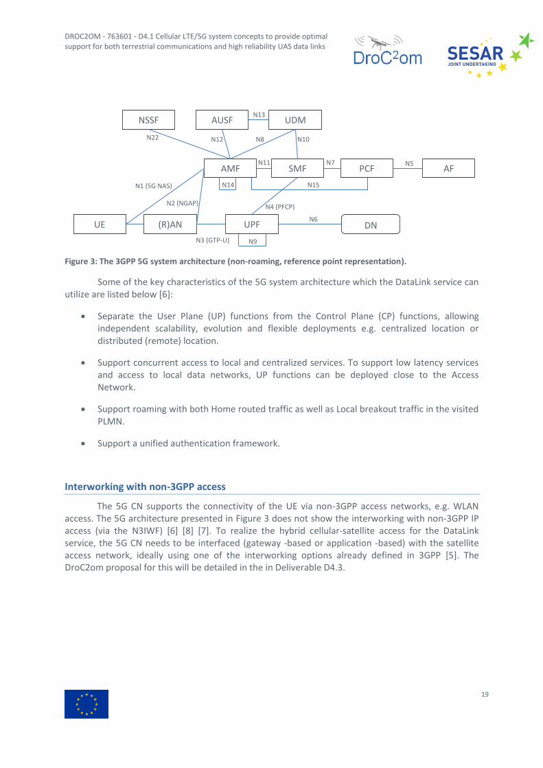
Figure 3: The 3GPP 5G system architecture (non-roaming, reference point representation).
Some of the key characteristics of the 5G system architecture which the DataLink service can utilize are listed below [6]:
Separate the User Plane (UP) functions from the Control Plane (CP) functions, allowing independent scalability, evolution and flexible deployments e.g. centralized location or distributed (remote) location.
Support concurrent access to local and centralized services. To support low latency services and access to local data networks, UP functions can be deployed close to the Access Network.
Support roaming with both Home routed traffic as well as Local breakout traffic in the visited PLMN.
Support a unified authentication framework.
Interworking with non-3GPP access
The 5G CN supports the connectivity of the UE via non-3GPP access networks, e.g. WLAN access. The 5G architecture presented in Figure 3 does not show the interworking with non-3GPP IP access (via the N3IWF) [6] [8] [7]. To realize the hybrid cellular-satellite access for the DataLink service, the 5G CN needs to be interfaced (gateway -based or application -based) with the satellite access network, ideally using one of the interworking options already defined in 3GPP [5]. The DroC2om proposal for this will be detailed in the in Deliverable D4.3.
UE (R)AN UPF
AMF SMF PCF AF
NSSF AUSF UDM
DN
N1 (5G NAS)
N2 (NGAP)
N3 (GTP-U)
N4 (PFCP)
N5
N6
N7
N8
N9
N10
N11
N12
N13
N22
N15 N14

EDITION [01.00]
20
2.2 State-of-the-art cellular radio access
2.2.1 LTE/4G: E-UTRAN
The 3GPP E-UTRAN architecture is depicted in Figure 4. The main functionalities of the E-UTRAN are listed below along with the main relationship between these and the DataLink service.
Radio resource management (RRM): radio bearer control, radio admission control, radio mobility control, multi-user dynamic scheduling of the radio (time-frequency) resources to/from served UEs; this includes also all signalling and data exchange between eNodeB via the X2 interface.
o The availability, reliability and throughput of the DataLink service heavily relies on the RRM functionalities, especially on the algorithms used for the multi-user scheduling of the radio (time-frequency) resources.
o The mobility management (UEs changing serving cells) is an important functionality, and needs to ensure ‘always-connected’ DataLink service.
Security: Encryption of the data transmitted over the air-interface (UE-Uu)
o This functionality provides the basis of a secure (authentication and authorization) end-to-end data bearer carrying DataLink packets.
Connectivity to the EPC: Signalling to MME and data bearer to S-GW
o Routing the end-to-end data bearer carrying DataLink packets.
o Provides mechanism for S1 mobility (between eNodeB without direct X2).
Figure 4: The 3GPP E-UTRAN architecture.
UE eNodeB1
MME/S-GW
LTE-Uu
S1
eNodeB2
UE
X2 LTE-Uu
S1
E-URAN
MME/S-GW
S1
eNodeB3 UE LTE-Uu
S1
EPC

DROC2OM - 763601 - D4.1 Cellular LTE/5G system concepts to provide optimal support for both terrestrial communications and high reliability UAS data links
21
2.2.2 5G: NG-RAN
The 3GPP NG-RAN architecture is depicted in Figure 5. The main functionalities of the NG-RAN are listed below along with the main relationship between these and the DataLink service.
Radio resource management (RRM): radio bearer control, radio admission control, radio mobility control, multi-user dynamic scheduling of the radio (time-frequency) resources to/from served UEs; this includes also all signalling and data exchange between gNB via the Xn interface and between gNB-DUs belonging to the same gNB-CU.
o The availability, reliability and throughput of the DataLink service heavily relies on the RRM functionalities, especially on the algorithms used for the multi-user scheduling of the radio (time-frequency) resources.
o The mobility management (UEs changing serving cells) is an important functionality, and needs to ensure ‘always-connected’ DataLink service.
o Dual/multi-connectivity, natively supported in the NG-RAN, can ensure high DataLink reliability especially in dense urban scenarios where the gNB-CU/DU configurations are more likely to be deployed. In a Non-Standalone deployment mode (LTE EPC based), a 5G UE can connect to both a LTE eNB and a 5G gNB using dual-connectivity, ensuring fast switching and reduced handover delays.
Security: Encryption of the data transmitted over the air-interface (5G-Uu)
o This functionality provides the basis of a secure (authentication and authorization) end-to-end data bearer carrying DataLink packets.
Connectivity to the 5GC (AMF/UPF):
o Routing the end-to-end data bearer carrying DataLink packets.
o Provides mechanism for NG mobility (between gNB without direct Xn).
gNB3
UE gNB1
AMF/UPF
5G-Uu
NG
gNB2
UE
Xn 5G-Uu
NG-RAN
UE
5G-Uu
5GC
gNB-DU
gNB-DU
gNB-CU
F1
Xn
NG NG
UE

EDITION [01.00]
22
Figure 5: The 3GPP NG-RAN architecture (standalone deployment).
2.3 Preliminary proposals for integrated hybrid cellular-satellite DataLink solutions
2.3.1 State-of-the-art hybrid access solutions
Here we provide brief descriptions of the available state-of-the art (SoA) technical solutions which have potential and/ or are related to the hybrid access solutions targeted in DroC2om. Details will be provided in the follow-up Deliverables D4.2 and D4.3 on the mechanisms selected to be used in the hybrid access DroC2om concept.
Mobile broadband hybrid access
The Broadband Forum has specified a hybrid access network architecture, primarily used for combined 3GPP mobile and fixed broadband access [9]. There are three main transport models, as
summarized below. These rely on different capabilities for the hybrid-access consumer premises equipment (HCPE), the hybrid-access gateway (HAG) and functionality required in the access network infrastructure.
Layer 3 Overlay Tunnelling
“The connectivity between the HCPE and the HAG is established using tunnels on top of the access infrastructure. The tunnels are established between the HCPE and the HAG over each of the access paths. The HCPE is responsible for managing the tunnel (both establishment and tear down) as well as upstream forwarding decisions. The HAG is responsible for downstream forwarding decisions. The implementation itself is access network agnostic, therefore no changes to either the fixed broadband or the 3GPP access networks are necessary”.
Layer 3 Network-based Tunnelling
“The connectivity between the HCPE and the HAG is realized by making use of the native technologies in both the fixed broadband (e.g. IPoE/PPPoE) and 3GPP access networks, from HCPE to BNG and from HCPE to eNodeB respectively. On setup, the network establishes the tunnels to the HAG on behalf of the subscriber’s HCPE and stitches traffic from the access sessions to those tunnels, in order to reach the HAG. Each Hybrid Access path is the end-to-end path resulting from stitching the access session in the respective access network with the corresponding tunnel from the access network to the HAG”.
Layer 4 Multipath (Multi Path TCP)
“The connectivity between the HCPE and the HAG is established using a Layer 4 multipath transport service enabling IP flows to use multiple paths in the Hybrid Access path group simultaneously. As an example, a L4 multipath implementation using MPTCP sets up multiple TCP sub-flows over the different access networks and utilizes real time HCPE to HAG flow control. The

DROC2OM - 763601 - D4.1 Cellular LTE/5G system concepts to provide optimal support for both terrestrial communications and high reliability UAS data links
23
HCPE and HAG are responsible for managing the MPTCP paths, including establishment and tear down”.
Multi-path TCP [10] [11] provides an application level connectivity option using multiple TCP flows transmitted over different paths and/or access networks, thus improving the overall reliability and latency of the data connection.
Generic Routing Encapsulation (GRE)
GRE [12] provides a control plane solution (tunnel management, policy and traffic control) between the HCPE an HAG via “extensions which enable operators to construct residential networks that are able to access the provider service through more than one hybrid access networks simultaneously in order to satisfy the higher bandwidth requirements”.
Locator Identity Separation Protocol (LISP)
LISP [13] “is a routing architecture that creates a new paradigm by splitting the device identity and its location into two different numbering spaces. This capability brings renewed scale and flexibility to the network in a single protocol, enabling the areas of mobility, scalability and security”.
“LISP has the capability to provide a transparent multi-homing solution for the end systems which allows load sharing between the different radio technologies dependent on the available QoS. It also solves the network mobility problem of the aircraft network and together with GETVPN it provides a maintainable security solution”.
Asymmetric Extended Route Optimization (AERO)
AERO [14] “supports mobility by modelling the enterprise network as a virtual link through a process known as encapsulation. AERO is based on a Non-Broadcast, Multiple Access (NBMA) tunnel virtual link model, where all nodes appear as neighbours the same as if they were attached to the same physical link”.
The AERO “system tracks mobile devices through control message signalling and an efficient routing system. Dynamic link selection, mobility management, quality of service (QoS) signalling and route optimization are naturally supported through dynamic neighbour cache updates, while prefix delegation (PD) is supported by the Dynamic Host Configuration Protocol for IPv6 (DHCPv6)”.

EDITION [01.00]
24
2.3.2 Preliminary DroC2om proposals
The hybrid cellular-satellite DataLink solution targeted in DroC2om has to re-use as much as possible from the SoA solutions and architectures. This is needed in order to be able to integrate the DroC2om solution into existing access networks (3GPP and satellite), without requiring excessive changes or upgrades.
In Figure 6 we show the preliminary high-level block diagram of the hybrid cellular-satellite DataLink solution to be developed in DroC2om. This is based on the SoA access solutions described in Section 2.3.1, where we have replaced the fixed broadband access path with the satellite access path. Therefore, the main activity in DroC2om will focus on working out the details for the functionalities required in the Hybrid (multilink) DataLink Gateway (HDLGW) and the Hybrid (multilink) DataLink User Equipment (HDLUE) entities. These will be addressed in Deliverables D4.2 and D4.3.
Figure 6: High level block diagram of the hybrid cellular-satellite DataLink solution targeted in DroC2om.

DROC2OM - 763601 - D4.1 Cellular LTE/5G system concepts to provide optimal support for both terrestrial communications and high reliability UAS data links
25
3 DataLink performance evaluation
3.1 Scenarios and methodology
3.1.1 Scenario modelling
For this Deliverable D4.1 work, the exploratory scenarios described in Section 2.1 of Deliverable D2.1 [2] have been mapped to two generic performance evaluation scenarios: rural and urban, characterised by the type of terrestrial network deployments in typical rural and urban geographical areas, respectively.
Furthermore, the terrestrial network models used for the analysis of these two types of deployments can be further differentiated into:
1. Regular 3GPP LTE network deployment scenarios and propagation models. These scenarios are well documented and have been used for extensive reference studies of aerial vehicles communication support in LTE, as presented in [15] [16] [17]. Annex B.1 provides the detailed description of these evaluation scenarios and the corresponding reference performance results are documented Annex B.2.
2. Site specific, real LTE network, deployment scenarios. These scenarios are used to establish a more realistic performance estimation for currently deployed radio access networks and user terminal configurations. The propagation models are derived either from radio measurements or adopted from corresponding 3GPP scenarios. Based on the measurement campaigns described in Deliverable D5.1 [3], the investigated site-specific deployments correspond to the typical Danish rural and urban terrestrial LTE network deployments. Section 3.2.2 provides the detailed description of these evaluation scenarios and the corresponding reference performance results are documented in Section 3.2.3.
3.1.2 Evaluation methodology
A preliminary report of the experimental drone measurement campaigns, and analysis of the findings, conducted in the DroC2om project, is available in Deliverable D5.1 [3]. Existing cellular LTE networks were used in the experiments in urban and rural areas. The large-scale path loss and interference characteristics of the radio channel derived in Deliverable D5.1 [3] and radio channel models from [15] [18] [19] were used for the performance evaluations in Section 3 and Section 4.
The performance evaluations in this document are based on extensive system-level and mobility simulations using a dedicated and Nokia proprietary simulation environment according to the relevant 3GPP LTE radio specifications. The 3GPP C2 traffic profile is used and this can be considered as an average traffic condition for the DroC2om ‘high’ traffic profile (Section 3.2.1.1.2 of Deliverable D2.1) [2].
The reference performance results presented in Section 3.2.3 correspond to the case when no UAV DataLink specific network or terminal modifications are assumed. In Section 4 we detail our proposals for network and terminal enhancements such that the 3GPP C2 link requirements are met [2].

EDITION [01.00]
26
In addition to the path loss and interference characteristics, the Deliverable 5.1 [3] also presented some very first measurements to characterise LTE radio mobility aspects for a drone connected to cellular networks in an urban scenario. These initial measurements were used for the experimental results presented in Section 3.2.4.
3.2 Evaluation results
3.2.1 Key performance indicators
The performance evaluations presented in this section are analysed in terms of the following radio performance KPIs:
Average UE downlink (forward link) SINR (dB), over the total simulation time (the averaging is performed in dB domain)
Average UE downlink (forward link) throughput (Mbps), over the total simulation time
Average UE uplink (forward link) SINR (dB), over the total simulation time (the averaging is performed in dB domain)
Average UE uplink (forward link) throughput (Mbps), over the total simulation time
The average number of HOs over time per UE (HO/sec/UE), over the total simulation time
The average number of RLFs over time per UE (RLF/sec/UE), over the total simulation time
Average time in Qout2 per UE (%), defined as the ratio between the total time in Qout and the total number of UEs (all cells) normalized to the total simulation time
Outage probability (%), defined as the ratio between the time in Qout and the total simulation time, for each UE, averaged over all UEs (all cells)
Note
The average downlink UE throughput results are presented and analysed in the view of the 50 ms latency requirement corresponding to the 3GPP C2 baseline traffic profile [2]. Therefore, the downlink results using this C2 traffic model show a maximum achievable rate of 200 kbit/s corresponding to a transmission at 100 kbit/s of the C2 data packet (1250 Bytes) within 50 ms, while the C2 packet arrival rate is 100 ms. In uplink, for UAVs the C2 traffic model was not used, and the maximum data rate can be above the minimum required 200 kbit/s.
2 The “Time in Qout” is defined as the time interval starting when the UE’s downlink channel SINR falls below
-8 dB until it rises above -6 dB.

DROC2OM - 763601 - D4.1 Cellular LTE/5G system concepts to provide optimal support for both terrestrial communications and high reliability UAS data links
27
3.2.2 Site-specific scenarios
The network deployment layouts for the site-specific scenarios investigated are depicted in Figure 7. In both cases the simulated network layouts have been extended using the ‘wrap-around’ method, so the performance results are collected from an equivalent network area which is 7 times larger. The corresponding scenario modelling parameters are listed in Table 3.
The aerial vehicles were deployed with uniform random spatial distribution (2-D, fixed height) with average densities of 0.1 or 1 per sector (see Table 3), which yields the spatial densities of approximately 0.013 AVs/ km2 in the Rural Fyn scenario and approximately 0.018 AVs/ km2 or 0.18 AVs/ km2 in Urban Aalborg scenarios.
Figure 7: The site-specific Rural Fyn (top) and Urban Aalborg (bottom) radio network deployment layouts. Radio site locations and sector (cell) orientations are depicted.

EDITION [01.00]
28
Parameter Value
Carrier frequency Rural Fyn: 10MHz in 800MHz band
Urban Aalborg: 20MHz in 800MHz band
Number of sectors (cells) and geographical area
Rural Fyn: 7*212 sectors, ~11200 km2
Urban Aalborg: 7*300 sectors, ~11200 km2
ISD Rural Fyn: avg. 3000m
Urban Aalborg: avg. 800m
BS antenna height Rural Fyn: avg. 33m
Urban Aalborg: avg. 30m
BS antenna down-tilt (mechanical + electrical)
Rural Fyn: avg. 4.6 degree
Urban Aalborg: 4.8 degree
AV UE height 15m, 30m, 60m, 120m
Terrestrial UE height 1.5m
AV UE velocity 30 km/h (linear flight path, at constant AV UE height)
Terrestrial UE velocity 30 km/h (linear path, at constant Terrestrial UE height)
Traffic model Downlink (forward link, network-to-AV):
- Terrestrial UEs: FTP model 3 with 0.5 MBytes buffer and variable packet inter-arrival time set to achieve approx. 30% or 67% in Rural Fyn, 57% in Urban Aalborg, resource utilisation (cell load). - AV UEs: Command and control traffic model with 100 kbits buffer size and 100ms arrival rate (3GPP C2 traffic profile).
Uplink (reverse link, AV-to-network):
- Terrestrial and AV UEs: Full buffer, time-burstiness follows downlink.
Number of AVs In average, 10 UEs (AV & Terrestrial) per sector and:
a) Reference: 0 AVs (all terrestrial UEs)
b) UAV: 1% AVs per sector (0.1 AV per sector), i.e. 0.013 AVs/ km2 in Rural
Fyn and 0.018 AVs/ km2 in Urban Aalborg
c) UAV: 10% AVs per sector (1 AV per 1 sectors) – Urban Aalborg only – i.e. 0.18 AVs/ km
2 in UMa
LOS/NLOS Rural Fyn: Not used. Path loss model derived from measurements.
Urban Aalborg: Dynamic; determined based on 2-D correlation distance and UE speed, for each UE towards each sector and subject to the RAN1 LOS probability channel model assumption. Path loss model specified in 3GPP RAN1.
MR triggering 3GPP A3 event
RLF triggering -8dB (SINR)
Simulation time 400 seconds (+10 seconds warm up time)
Resource allocation Terrestrial UE: Equal resources (all served UEs are scheduled)
Aerial UEs: Minimum required resources
Table 3: Mobility simulation assumptions for site-specific Rural Fyn [20] and Urban Aalborg scenarios.

DROC2OM - 763601 - D4.1 Cellular LTE/5G system concepts to provide optimal support for both terrestrial communications and high reliability UAS data links
29
3.2.3 Baseline performance results in site-specific scenarios
In this section we present a summary of the Rural Fyn scenario performance results, extensively discussed in reference [20]. The Urban Aalborg scenario results are explained in more details.
First, the site-specific scenarios have been investigated for increasing downlink traffic load, from 10 % up to around 70 %, to disclose the impact of the UAVs in various network conditions. In today’s LTE networks, in rural areas the typical average traffic load is around 10 %, with peak hours (busy hours) loads around 25-30 %; similarly, in urban areas the typical average load is around 20-30 % with peaks around 60-70 %. Therefore, the traffic load values used in our investigations should also be interpreted as potential load values in different time of the day periods, not just simply an average value during a day/week time frame.
Next, for the detailed radio mobility studies, we have selected only two reference traffic load levels, representative for medium and high load conditions. These results are presented in the same format as used for the baseline 3GPP results provided in Section B.1.
Baseline results for Rural Fyn scenario
The baseline radio performance results versus the network traffic load are presented in Figure 8, for different UAV flight heights. These results clearly highlight the impact of traffic load (generated by terrestrial UEs) on the selected UAV’s radio KPIs: DL SINR, DL throughput and outage.
The average traffic load levels used in the mobility performance studies have been selected as follows: 30% for medium load 67 % for high load. The UAV penetration was 1 % (1 AV per 10 sectors). The baseline mobility performance results are presented in Figure 9. Figure 10 shows the corresponding radio performance of the terrestrial UEs, i.e. under the same load conditions, UAV penetration and set of UAV heights.

EDITION [01.00]
30
Figure 8: Baseline radio performance of Aerial Vehicles in the Rural Fyn scenario.

DROC2OM - 763601 - D4.1 Cellular LTE/5G system concepts to provide optimal support for both terrestrial communications and high reliability UAS data links
31
Figure 9: Baseline radio mobility performance of Aerial Vehicles in the Rural Fyn scenario for two network load points (30 % for medium load 67 % for high load).
EDITION [01.00]
32
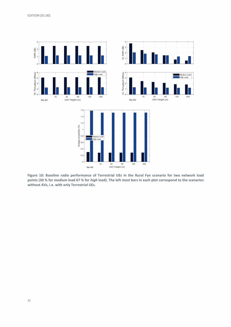
Figure 10: Baseline radio performance of Terrestrial UEs in the Rural Fyn scenario for two network load points (30 % for medium load 67 % for high load). The left most bars in each plot correspond to the scenarios without AVs, i.e. with only Terrestrial UEs.
No AV
No AV
No AV

DROC2OM - 763601 - D4.1 Cellular LTE/5G system concepts to provide optimal support for both terrestrial communications and high reliability UAS data links
33
Main conclusions for baseline Rural Fyn scenario
Average UAV DL SINR and Throughput
o In medium traffic load conditions, these KPIs are impacted by the UAV flight height; at heights above 60 m the target average throughput of 200 kbits/ss cannot be reached due to high downlink radio interference.
o In high traffic load conditions, these KPIs are significantly impacted by the UAV flight height; at any heights above 15 m the target average throughput of 200 kbits/s cannot be reached due to very high radio interference.
Average UAV UL SINR and Throughput
o In both medium and high traffic load conditions, this KPIs are impacted by the UAV flight height; however, due to the low number of the UAVs, at any heights the target average throughput of 200 Kbps can easily be achieved.
The outage probability is significantly increased for UAV flight heights above 15 m, and strongly depends on the traffic load conditions; the 99.9 % radio connectivity availability cannot be reached, regardless of the UAV flight height, even in the medium traffic load scenario.
The downlink performance (throughput and outage) of the terrestrial UEs is not significantly impacted by the presence of the UAVs.
The uplink throughput performance of the terrestrial UEs in medium traffic load conditions decreases significantly for UAV flight heights above 15 m.

EDITION [01.00]
34
Baseline radio mobility results for Urban Aalborg scenario
The Rural Fyn results have clearly highlighted the impact of traffic load (generated by
terrestrial UEs) on the selected UAV’s radio KPIs (Figure 8) even at very low UAV penetration ratio of 1 % (1 AV per 10 sectors). Thus, for the Urban Aalborg scenario, we only used two representative network traffic load levels – 30 % for medium load 57 % for high load – combined (partly) with two cases of UAV penetration ratios: 1 % (1 AV per 10 sectors) and 10 % (1 AV per 1 sectors). The average 57 % load level, for the high load case, was set lower compared to the 67 % high load case in the Rural Fyn scenario. This selection was made on the rationale that in a denser radio access network, such as the Urban Aalborg, lower traffic load levels are sufficient to generate critically high interference levels; thus, there was no need to investigate higher load levels, when a critical operating point was achieved already at 57 % load.
The baseline mobility performance results for AVs are presented in Figure 11 and Figure 12; Figure 13 and Figure 14 show the corresponding radio performance of the terrestrial UEs, i.e. under the same load conditions, UAV penetration and set of UAV heights.

DROC2OM - 763601 - D4.1 Cellular LTE/5G system concepts to provide optimal support for both terrestrial communications and high reliability UAS data links
35
Figure 11: Baseline radio mobility performance of Aerial Vehicles in the Urban Aalborg scenario for two network load points (30 % for medium load 57 % for high load) and 1 % UAV penetration ratio.

EDITION [01.00]
36
Figure 12: Baseline radio mobility performance of Aerial Vehicles in the Urban Aalborg scenario for medium network load (30 %) and 1 % or 10 % UAV penetration ratio.
DROC2OM - 763601 - D4.1 Cellular LTE/5G system concepts to provide optimal support for both terrestrial communications and high reliability UAS data links
37
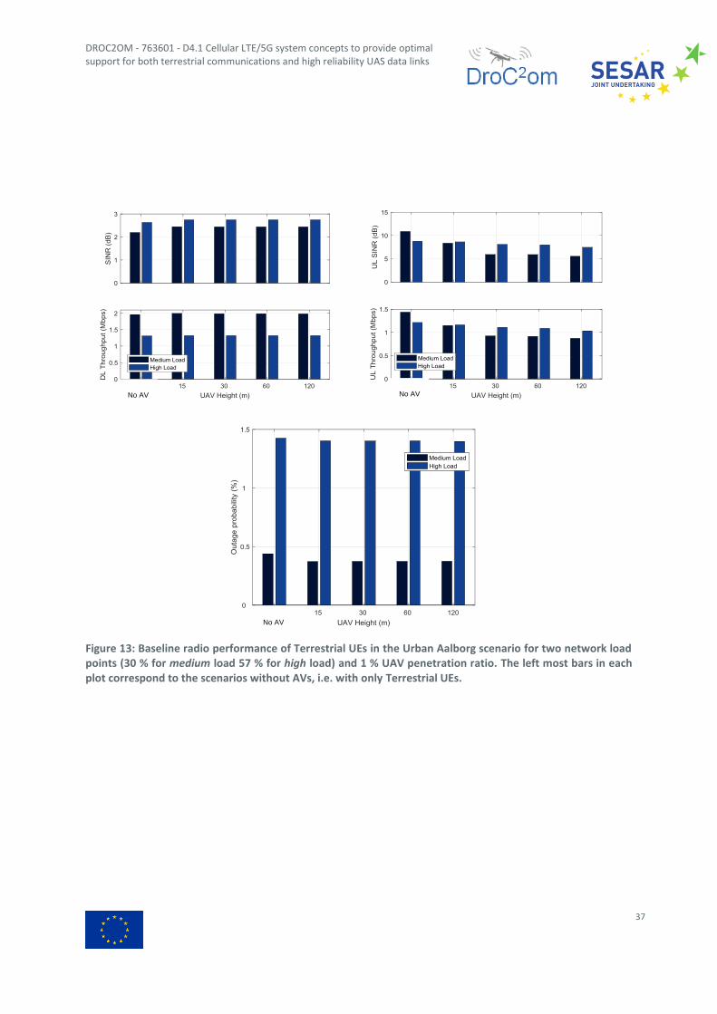
Figure 13: Baseline radio performance of Terrestrial UEs in the Urban Aalborg scenario for two network load points (30 % for medium load 57 % for high load) and 1 % UAV penetration ratio. The left most bars in each plot correspond to the scenarios without AVs, i.e. with only Terrestrial UEs.
No AV
No AV
No AV
EDITION [01.00]
38
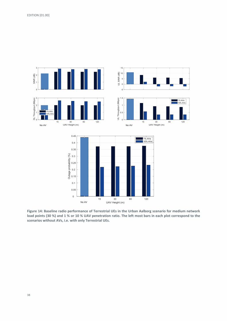
Figure 14: Baseline radio performance of Terrestrial UEs in the Urban Aalborg scenario for medium network load points (30 %) and 1 % or 10 % UAV penetration ratio. The left most bars in each plot correspond to the scenarios without AVs, i.e. with only Terrestrial UEs.
No AV
No AV
No AV

DROC2OM - 763601 - D4.1 Cellular LTE/5G system concepts to provide optimal support for both terrestrial communications and high reliability UAS data links
39
Main conclusions for Urban Aalborg scenario
Average UAV DL SINR and Throughput
o In medium traffic load conditions, these KPIs are impacted by the UAV flight height; at heights above 30 m the target average throughput of 200 kbits/scannot be reached due to high downlink radio interference.
o In high traffic load conditions, these KPIs are significantly impacted by the UAV flight height; at any UAV heights above 15 m the target average throughput of 200 kbits/s cannot be reached due to very high radio interference.
o The penetration ratio of the UAVs does not significantly impact these KPIs
Average UAV UL SINR and Throughput
o In both medium and high traffic load conditions, this KPIs are impacted by the UAV flight height; however, due to the low number of the UAVs, even with 10% penetration ratio, at any UAV heights the target average throughput of 200 kbit/s can easily be achieved.
The outage probability is significantly increased for UAV flight heights above 15 m, and strongly depends on the traffic load conditions; the 99.9 % radio connectivity availability cannot be reached, regardless of the UAV flight height, even in the medium traffic load scenario and low UAV penetration ratio.
The downlink performance (throughput and outage) of the terrestrial UEs is not significantly impacted by the presence of the UAVs at low penetration ratio of 1%; however, when the number of UAVs is increased, the downlink performance of the terrestrial UEs is slightly increased as well.
The uplink throughput performance of the terrestrial UEs decreases for UAV flight heights above 15 m; the uplink average throughput of the terrestrial UE decreases significantly with increased penetration ratio of the UAVs.

EDITION [01.00]
40
3.2.4 Baseline performance results in 3GPP scenarios
In this section we re-cap the main findings from the studies performed using the 3GPP Rural Macro and Urban Macro deployment scenarios. Annex B.1 provides the detailed description of these evaluation scenarios and the corresponding reference performance results are documented in detail in Annex B.2.
Main conclusions for baseline 3GPP Rural Macro scenario
The average UAV DL SINR and Throughput are significantly impacted by the UAV flight height; at heights above 50 m the target average throughput of 200 kbits/s cannot be reached due to very high downlink radio interference.
The average UAV UL SINR and Throughput are significantly impacted by the UAV flight height; at heights above 100 m the target average throughput of 200 kbits/s cannot be reached due to very high uplink radio interference.
For the high UAV flight speeds of 160 km/h, the increased downlink radio interference also impacts the mobility performance KPIs, and significantly increased number of RLF is observed at UAV flight heights above 50 m.
The outage probability is significantly increased for UAV flight heights above 20 m, and strongly depends also on the UAV flight speed; the 99.9 % radio connectivity availability cannot be reached, regardless of the UAV flight height.
The penetration of UAVs (1 or 5 per cell) has minor impact on the downlink/uplink radio performance results; this is due to the relatively high(er) traffic load conditions generated by the terrestrial UEs.
The downlink performance (throughput and outage) of the terrestrial UEs is not significantly impacted by the presence of the UAVs.
The uplink throughput performance of the terrestrial UEs decreases for higher number for UAVs and UAV flight heights above 20 m.
Main conclusions for baseline 3GPP Urban Macro scenario
The average UE DL SINR and Throughput are significantly impacted by the UAV flight height; at heights above 20 m the target average throughput of 200 kbits/s cannot be reached due to very high radio interference.
The average UE UL SINR and Throughput are significantly impacted by the UAV flight height; at heights above 20 m the target average throughput of 200 kbits/s cannot be reached due to very high uplink radio interference.
For the high UAV flight speeds of 160 km/h, the increased radio interference also impacts the mobility performance KPIs, and significantly increased number of RLF is observed at UAV flight heights above 20 m.

DROC2OM - 763601 - D4.1 Cellular LTE/5G system concepts to provide optimal support for both terrestrial communications and high reliability UAS data links
41
The outage probability is significantly increased for UAV flight heights above 20 m, and strongly depends also on the UAV flight speed; the 99.9 % radio connectivity availability cannot be reached, regardless of the UAV flight height.
The penetration of UAVs (1 or 5 per cell) has medium impact on the downlink/uplink radio performance results; this is likely due to the relatively high(er) traffic load conditions generated by the terrestrial UEs.
The downlink performance (throughput and outage) of the terrestrial UEs is not significantly impacted by the presence of the UAVs.
The uplink throughput performance of the terrestrial UEs is decreases for higher number for UAVs and UAV flight heights above 20 m.

EDITION [01.00]
42
3.3 First experimental results
The radio mobility experiments performed in Workpackage 5 and described in Deliverable D5.1 [3] yielded a few early results which are documented in this section. The target is to start quantifying the practically achievable radio access reliability level – 99.9 % with delays below 50 ms for the C2 link [2] – when using current LTE networks for the C2 communications. These results and observations will be further refined and updated based on the new experimental campaign planed within the Workpackage 5 activities.
Figure 15 and Figure 16 show the test UAV flight map (route), at 40 m height, along with the LTE radio cells in the two different MNOs, Network 1 and Network 2, which have been measured simultaneously. The radio hand-over events, separately within each Network, are marked in these figures with green triangles.
In Figure 17 we show the recorded traces for the RSRP, RSRQ and downlink packet delay KPIs, during the UAV flight at 40 m height, in the two networks.
We have performed a preliminary analysis of a dual-LTE radio access mechanism. Figure 18 shows the achieved average outage levels in the two separate Networks and when using the dual-LTE radio access.
Observations
The average RSRP levels in the two networks are significantly different, with 20 dB higher average values in Network 1.
The average RSRQ levels in the two Networks are not very much different (3 dB difference only). However, the fluctuations are more pronounced in Network 1, where the probability to have RSRQ levels below -20 dB is approximately 40 times higher compared to Network 2.
The average DL packet delays are significantly different in the two Networks. In Network 1 the probability to have delays above 50 ms is approximately 15 times higher compared to Network 2.
The preliminary analysis indicates that a dual-LTE access mechanism can significantly reduce the downlink packet delays, and achieve the target reliability of 99.9 % probability for packet delays below 50 ms.

DROC2OM - 763601 - D4.1 Cellular LTE/5G system concepts to provide optimal support for both terrestrial communications and high reliability UAS data links
43
Figure 15: UAV flight route at 40 m height, and radio hand-over events for test UE connected to Network 1. Only the Network 1 radio cells are depicted.
Figure 16: UAV flight route at 40 m height (same as in Figure 15), and radio hand-over events for test UE connected to Network 2. Only the Network 2 radio cells are depicted.
LTE cells in Network 1
Flight path Radio hand-over events
LTE cells in Network 2
Radio hand-over events

EDITION [01.00]
44
Figure 17: The RSRP, RSRQ and downlink packet delay KPIs recorded during the UAV flight at 40 m height. The separate results in Network 1 (blue) and Network 2 (red) depicted. The radio hand-over events, separately within each Network, are marked with green triangles.
Figure 18: The radio access outage levels achievable in the two separate Networks and with a theoretical dual-LTE radio access scheme, during the UAV flight at 40 m height depicted in Figure 15 and Figure 16, and based on the analysis of the KPIs shown in Figure 17.
Average = -71 dBm
Average = -92 dBm
Average = -14 dB
Average = -11 dB
11.5%
1.5%
0.015%

DROC2OM - 763601 - D4.1 Cellular LTE/5G system concepts to provide optimal support for both terrestrial communications and high reliability UAS data links
45
3.4 Performance models to be used in WP3
In this Section we provide the first description of the planned interaction between Workpackage 3 and Workpackage 4 activities.
We describe here the preliminary content of the data exchange, for cellular radio access performance evaluation and visualisation [21]. In Deliverable D4.2 a similar description will be provided for satellite-only radio access evaluations. The details of this data exchange will be refined iteratively, based on the on-going development of the simulation environment in Workpackage 3 and the hybrid access solution developments in Workpackage 4.
Data flow from Workpackage 3 to Workpackage 4
In Workpackage 3, radio (channel) data time traces are to be generated based on the detailed radio propagation models implemented in the simulation environment described in Deliverable D3.1 The radio data time traces are provided as input to Workpackage 4 performance simulations.
Cellular -only radio data time traces
o The preliminary content of the cellular radio data time trace file is outlined in Table 4.
Satellite -only radio data time traces
Data fields Description
Time step Time resolution of the data included in the trace file
UAV coordinates (X,Y,Z) 3-D coordinates of the UAV
All eNBs:
Total Path Gain list
The total path gains between the UAV and all (or a subset potentially within certain range only. TBD) cells (eNBs), including antenna gains, cable losses and terminal losses
All eNBs:
ID list
The list of all cell IDs (potentially within certain range only. TBD) which are detected at the UAV with an RSRP above a certain threshold
All eNBs, Terrestrial traffic load:
Downlink list
The DL traffic load generated by terrestrial users, corresponding to the eNB list specified
All eNBs, Terrestrial traffic load:
Uplink list
The UL traffic load generated by terrestrial users, corresponding to the eNB list specified
Table 4: Preliminary content of the cellular radio data time traces provided by Workpackage 3 for cellular radio access performance simulations in Workpackage 4.
EDITION [01.00]
46
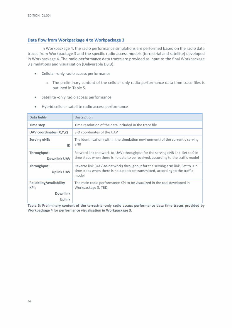
Data flow from Workpackage 4 to Workpackage 3
In Workpackage 4, the radio performance simulations are performed based on the radio data traces from Workpackage 3 and the specific radio access models (terrestrial and satellite) developed in Workpackage 4. The radio performance data traces are provided as input to the final Workpackage 3 simulations and visualisation (Deliverable D3.3).
Cellular -only radio access performance
o The preliminary content of the cellular-only radio performance data time trace files is outlined in Table 5.
Satellite -only radio access performance
Hybrid cellular-satellite radio access performance
Data fields Description
Time step Time resolution of the data included in the trace file
UAV coordinates (X,Y,Z) 3-D coordinates of the UAV
Serving eNB:
ID
The identification (within the simulation environment) of the currently serving eNB
Throughput:
Downlink UAV
Forward link (network-to-UAV) throughput for the serving eNB link. Set to 0 in time steps when there is no data to be received, according to the traffic model
Throughput:
Uplink UAV
Reverse link (UAV-to-network) throughput for the serving eNB link. Set to 0 in time steps when there is no data to be transmitted, according to the traffic model
Reliability/availability KPI:
Downlink
Uplink
The main radio performance KPI to be visualized in the tool developed in Workpackage 3. TBD.
Table 5: Preliminary content of the terrestrial-only radio access performance data time traces provided by Workpackage 4 for performance visualisation in Workpackage 3.

DROC2OM - 763601 - D4.1 Cellular LTE/5G system concepts to provide optimal support for both terrestrial communications and high reliability UAS data links
47
4 Cellular radio mechanisms for DataLink provisioning
4.1 Proposed concepts
This section contains the enhancements which can be made to cellular networks to enhance their handling of UAVs, addressing some of the issues mentioned in the previous section
4.1.1 Downlink
In the downlink the interference is coming from the other base stations and the amount of impact depends on the load as was shown in the previous chapter. In this section we present a number of potential solutions to the downlink interference problem. The can be split into 2 categories: 1) UAV based enhancements and 2) network based enhancements and the different solutions are described in the following subsections.
Beam selection at the UAV
Antenna selection with two or more antenna elements can be equivalent to a very simple beam selection when the antennas are placed on the drone at the right spacing and orientations. It is easy to increase the number of beams to four or six by adding additional directional antennas antenna elements, as depicted in Figure 19. The modeled beam patterns provide +6.6 dBi gain in the main direction and 13 dB front-to-sidelobe attenuation, which can be considered to account for the
non-ideal shape of the beams.
Figure 19: Antenna beam steering configurations for the drone with 2, 4 and 6 fixed beams
The receiver simply picks the beam direction with the best signal quality (RSRP or RSRQ) without adjusting the orientation of the drone. By doing so, the amount of interference received in the downlink is limited to the beam width of the beam, leading to a reduced overall outage as can be seen in Figure 6 for beam steering with different number of beams for the urban environment, which was described in the previous chapter. With 6 beams the achieved reliability is higher than the target 99.9%, even in the high load case.

EDITION [01.00]
48
Figure 20: Outage probability for a drone at 120 m in urban environments with and without fixed grid of beams for the medium and high network load case.
Furthermore, beam steering also provides advantages in the uplink as it gives a gain for the drone and limits the interference impact on terrestrial users, as the signal originating from the drone is only spread in a limited angle. This will be described in the next section.
Interference cancellation at the UAV
A typical way to address the downlink interference challenge is to implement advanced interference mitigation capabilities at the receiver in the drone. For example, LTE Release 11 supports interference rejection combining (IRC) techniques that perform interference suppression by means of linear operations. However, the number of sources that can be suppressed is limited by the number of antennas available at the UE side; and the efficiency is limited by the dominant-to-others interference ratio (DIR).
In Release 12, 3GPP addresses interference cancellation (IC) by proposing more advanced and non-linear techniques for network assisted interference cancellation and suppression (NAICS) [22]. These interference cancellation techniques try to reconstruct the interfering signal and remove it completely from the received signal, but they still limited in the number of interfering sources that can be cancelled and the cancellation efficiency similarly depends on a good DIR
We evaluate the potential of these techniques, implemented in the drone and enhancing the downlink performance, by assuming that we can remove up to 3 interferers perfectly (when at least 4 antenna elements are available). This will give the upper bound on the performance. Figure 21 shows the improvement of removing the 3 strongest potential interferers in terms of outage probability for the urban environments. The observed gain is limited and the target of a reliability of 99,9% is not reached. Reason for this is that the interference comes from many more than three interferers when being up in the air. Due to the high LOS probability and high cell density, the interference sources are close in power level, which can compromise the efficiency of such techniques in practical implementations.
0,001
0,01
0,1
1
Reference 2 beams 4 beams 6 beams
Ou
tage
pro
ba
bili
ty
medium load high load

DROC2OM - 763601 - D4.1 Cellular LTE/5G system concepts to provide optimal support for both terrestrial communications and high reliability UAS data links
49
Figure 21: Outage probability for a drone at 120 m in urban environments with and without interference cancellation, removing the 3 potential strongest interferers completely for the medium and high network
load case.
Inter Cell Interference Coordination (ICIC) at the network
A network based solution is downlink inter-cell interference coordination (ICIC). ICIC is a network-based solution for the DL interference that blanks certain time and frequency resources in the neighbour cells to protect the signal transmitted by a given BS. In other words, the resources that carry the C2 data can be protected from interfering transmission in the neighbour cells. Several standardized solutions for this exist. In LTE Release 8, the PDCCH occupies always the same position, in the beginning of each subframe. Therefore, to protect the PDCCH of a given cell in a subframe, all neighbour cells should be prevented from transmitting data in that subframe, a solution known as the Almost Blank Subframe (ABS). The drawback is the cost in capacity for the blanked cells. In Release 11, LTE introduced the enhanced PDCCH (ePDCCH), in which some data resources are converted into user-specific PDCCH resources, for one or more users. Using ePDCCH it is possible to perform ICIC by blanking only part of neighbour cells’ subframes, reducing the overall capacity loss.
The outage can be decreased by coordinating the downlink transmission from the right number of cells. Figure 22 shows the gain in outage versus the number of interferers removed for the urban and rural scenario. From the Figure, it can be concluded that quite some cells need to be muted to reach a reliability of 99,9% in case of high load. However, one needs to keep in mind that this reliability is for the C2 link, which only requires 100 kbps. This means the data transmission to and from the drone can be concentrated in time, such that for instance every 10th TTI is used for drone related transmissions. That would mean only in those TTIs the interfering cells need to be muted. An example of such a setup could be that a drone at 120 meters in the air with a 100 kbps C2 link uses every 10th TTI. In the high load scenario this will require muting the 8 strongest cells every 10th TTI, corresponding to removing 10% of the capacity of those cells.
0,01
0,1
1
Reference IC (3 cells)
Ou
tage
pro
ba
bili
ty
medium load high load

EDITION [01.00]
50
Figure 22: Outage probability for a drone at 120 m in urban environments with and without ICIC with 10 and 20 cells muted for the medium and high network load case.
Beam steering at the network
Besides beam steering from the UAV, beam steering from the network can also be used to mitigate interference. In vertical beam steering UAVs are served by different beams than the terrestrial users. This is illustrated in Figure 23. One of the simplest forms is vertical sectorization, where there is a sector to cover the ground (‘regular beams from cell A/B’ in the Figure) and a sector covering the sky (‘UAV beams from cell A’ in the Figure) with preferably an isolation in between those two sectors (‘blacklisted beams from cell A’ in the Figure). Under ideal circumstances there is no interference between the terrestrial users and the UAVs. Besides vertical sectorization one can create beams per UE when the number of available antennas is high enough. Performance simulation results for this type of solutions are to be potentially included in Deliverable 4.3.
Figure 23: Network beam steering concept for UAVs.
0,001
0,01
0,1
1
Reference ICIC (10 cells) ICIC (20 cells)
Ou
tage
pro
ba
bili
ty
medium load high load

DROC2OM - 763601 - D4.1 Cellular LTE/5G system concepts to provide optimal support for both terrestrial communications and high reliability UAS data links
51
4.1.2 Uplink
The interference issues are fundamentally different in the uplink, as in this case the UEs cause interference to the other users. In the case of UAVs, the worst case, as shown in the previous chapter is when one or more UAVs at a height around 100 m. are running an application with a lot of data in the uplink direction, like live streaming from a camera. This causes interference over a large area and may negatively affect the uplink of many users. Here we describe three methods which can be used to limit this effect.
UAV-specific uplink power control
A very straightforward method of limiting the uplink interference caused by a drone is to use different power control settings for drones as for terrestrial users, as the uplink LTE power control algorithm contains some adjustable parameters. We focus on the P0 parameter, which can be seen as the target received power level from the UE at the eNB. By using a lower P0 for drones compared to terrestrial users they will use a lower output power, and therefore cause less interference. As shown in Figure 24, where the UAV and terrestrial UE throughputs are shown for the reference (all UE having the same P0 settings) and two UAV-specific P0 settings (-3 and -6 dB) this will result in a higher throughput for the terrestrial users, as a part of the interference is removed, while the throughput of the UAV decreases, since less transmit power is available. Results are shown for medium load and for 1% of the users being UAVs, as in these case the effects are most visible.
Figure 24: Uplink throughput for UAV (left axis) and terrestrial (right axis) users for different UAV-specific power P0 settings for the medium network load case with 1% of the users being UAVs.
Beam selection at the UAV
The solution as described in the downlink section, gives uplink benefits at the same time, as using a beam to transmit from the UAV limits the spread of the interference. Due to the better desired signal connection, the uplink power control may lower the transmit power of the UAV, further decreasing the interference it creates.
0
0,2
0,4
0,6
0,8
1
1,2
0
2
4
6
8
10
12
14
Reference Power Control deltaP0 = - 3 dB Power Control deltaP0 = - 6 dB
Ave
rage
Ter
rest
ria
l UE
Thro
ugh
pu
t (M
bp
s)
Ave
rage
UA
V T
hro
ugh
pu
t (M
bp
s)
UAVs, 1% UAV
Terrestrial, 1% UAV

EDITION [01.00]
52
Figure 25: Uplink throughput for UAV (left axis) and terrestrial (right axis) users for different number of beams from the UAV for the medium network load case with 1% of the users being UAVs
Beam steering at the network
Also, the beam steering from the network can be utilised in the uplink as it isolates the interference between cellular and terrestrial users, as described in the previous section.
4.1.3 Mobility
As extensively shown in the previous chapter, the radio propagation environment is different in the sky compared to on ground level. This has impact on the handover performance, and without any adjustments this can lead to the following undesirable effects:
Very frequent handovers: a UAV sees many cells, which are good enough from a serving cell point of view. If the settings are such that the best cell is always chosen this may lead to a large number of handovers. Even though it is good (in terms of SINR) to be connected to the best cell all the time, every handover comes with a risk of a failure. A failure does not mean the connection is stopped, but there will be an interruption which should preferably be avoided. Therefore, keeping the frequency of the handovers as low as possible while keeping the signal level and quality at a good level is the target.
Ping-pong handovers: ping-pong handover means making consecutive handovers between 2 (or 3) cells. This is typically unnecessarily and should be avoided provided the quality and signal level is good enough. One typical example was observed during our measurements, where due to self-shadowing (due to the fuselage of the drone) when flying in circles between 2 cells, ping-pong handover happened constantly.
As the best neighbour cells are often different from the ground level, the neighbour cell list (NCL) which is designed for terrestrial users is not optimal for aerial users, as it may mean the best cell is not measured.
0
0,2
0,4
0,6
0,8
1
1,2
0
5
10
15
20
25
30
Reference 2 Beams 4 Beams 6 beams
Ave
rage
Ter
rest
ria
l UE
Thro
ugh
pu
t (M
bp
s)
Ave
rage
UA
V T
hro
ugh
pu
t (M
bp
s)
UAVs, 1% UAV
Terrestrial, 1% UAV

DROC2OM - 763601 - D4.1 Cellular LTE/5G system concepts to provide optimal support for both terrestrial communications and high reliability UAS data links
53
The above limitation can easily be avoided by means of dedicated UAV-mobility settings. These settings can be, for example:
Dedicated UAV Neighbour Cell List (NCL)
Different thresholds and triggers for measurement reporting
Different time to trigger
This is currently being studied in 3GPP [15]. One of the issues in having separate settings is the question how to know a UAV is in the air. This is further discussed in Section 4.1.6.
4.1.4 Multi-operator access
As already shown in the previous chapter, dual-LTE radio access, will greatly enhance the limitations of the current cellular networks by utilising diversity from two operator networks. This can easily be combined with any of the above techniques.
4.1.5 Frequency allocation
One option to avoid interference between UAVs and terrestrial users is to use a dedicated frequency for the UAVs. As the C2 link is critical for safe flights, the International Civil Aviation Organization (ICAO) has determined that CNPC links, which the C2 link is part of, for UAV must operate over protected aviation spectrum [23], which points in this direction. Furthermore, the ITU has estimated that a maximum of 34 MHz terrestrial spectrum and 56 MHz satellite spectrum is needed to support both VLOS and BVLOS UAV operations [24]. To meet such a requirement, the C-band at 5030-5091 MHz has been made available for drone control traffic at WRC-12 [25]. More recently, the WRC-15 decided that “assignments to stations of geostationary Fixed Satellite Service (FSS) networks may be used for UAS CNPC links” [26]. Cellular networks can provide service to both VLOS and BVLOS services in most areas without relying on satellite, provided the interference challenge is tackled. This means that in those area’s one may want to consider redirecting some of the satellite UAV related spectrum to cellular networks. Dedicated spectrum for UAVs mean that interference levels are lowered, as only UAVs are present in the network. However, it should be noted that when many UAVs are present in a small area, i.e. when the UAV density is high, then interference still may be an issue. In that case the other solutions described in this chapter may help tackling the interference.
The use of dedicated spectrum is not without any issues. Here we name a few:
Somebody needs to build the coverage for the spectrum. Most efficiently is to use the existing towers/masts.
Somebody needs to operate the spectrum. Obvious candidates are the operators, as they are already their networks which require similar operations.
The spectrum is meant for C2 traffic, which means it cannot be used for application data. If the drone has an application running requiring payload communication, it requires a second modem.
In general, the usage of the spectrum can be expected to be rather low, as it needs to be rolled out for wide area coverage, whereas the drone densities are much lower than smart phone densities.

EDITION [01.00]
54
Therefore, dedicated spectrum is less efficient than sharing spectrum with the terrestrial users. Within shared spectrum high reliability can be achieved by giving control traffic a high priority and use one of the interference mitigation methods described above.
4.1.6 Identification
As explained in the earlier sections it is preferred to use different settings for mobility and interference management for aerial and terrestrial users. Therefore, the network requires the capability of distinguishing aerial and pedestrian users, as is also expressed in the 3GPP study [15].
In the future, UAV control modems might have the capability of reporting their status and height to the base stations, as this is currently under discussion in 3GPP. However, the network ability to detect the airborne radio modems cannot rely solely on this. Legacy equipment, such as cameras, sensors or others can be attached to the UAV by its owner for different purposes and these devices do not have the capability of reporting their ground/aerial status. In reference [27] a method was presented to detect from the network side whether a UE is in the air or not. This work was further generalised in reference [28] with relative good results. However, the algorithms were only tested for rural areas.

DROC2OM - 763601 - D4.1 Cellular LTE/5G system concepts to provide optimal support for both terrestrial communications and high reliability UAS data links
55
5 Conclusions and recommendations
5.1 Summary and recommendations
In this Deliverable D4.1 we have provided an extensive analysis of 3GPP LTE terrestrial/cellular network support of UAS DataLink communications. The radio access and radio mobility mechanisms with direct impact on the performance of the DataLink have been described and evaluated. The overall scenario assumptions and requirements from Deliverable D2.1 [2] have been used. The evaluated UAS DataLink traffic model was selected to be the 3GPP C2 traffic profile [2]. This traffic profile can be considered as an average traffic within the DroC2om ‘high’ traffic profile (Section 3.2.1.1.2 of Deliverable D2.1 [2]) and from radio access point of view requires: 99.9 % reliability within a 50 ms delay budget for transmissions of 1250 Bytes packets every 100 ms. The evaluation models and methodology are a direct outcome of the radio measurement and experiments documented in Deliverable D5.1 [3].
First, the radio network architecture for 3GPP LTE and 5G NR have been introduced, highlighting the main elements which are to play a key role in the terrestrial cellular network support for DataLink and later also in the integrated hybrid cellular-satellite DataLink solutions. In this document we have started to sketch the first elements of the possible integrated hybrid cellular-satellite DataLink solutions. This activity was mostly based on the state-of-the-art hybrid access techniques specified in the Broadband Forum [9] and a priori knowledge on some of the UAS multilink concepts developed in previous research projects [13] [14].
Due to its modular principles, flexible configurations, and converged core approach, the 5G NR architecture is recommended as baseline for future UAS DataLink communications studies within DroC2om and other similar hybrid radio access research projects.
Next, we have analysed the baseline radio access and radio mobility performance in typical LTE network deployments, when providing the Command and Control (C2) DataLink service to UAVs. These reference studies have been carried out via numerical simulations in site-specific, rural and urban LTE network scenarios (Fyn and Aalborg, Denmark). Furthermore, in all simulations, also the usual terrestrial users have been taken in consideration and their performance analysed. The results clearly indicate that even in both rural and urban scenarios the downlink network traffic load, which is mostly generated by terrestrial users, is a dominant factor in the performance of the UAS DataLink services. Conversely, the UAS DataLink service can significantly degrade the uplink performance of all users in the network. Under the 3GPP C2 traffic profile, the 99.9 % reliability requirement was shown as being impossible to meet at higher UAV heights than 15-20 m, even with very low spatial density of UAVs and in low network traffic load conditions. However, for Droc2om ‘low’ traffic profile the performances are expected to improve significantly and current LTE networks might be able to provide the communication link for UAS DataLink services.
The first experimental results on radio mobility, performed in Urban Aalborg using connectivity provided by two different NMOs (live LTE networks), have been analysed. Like in simulations, these measurements also highlighted the difficulties in providing the 99.9 % reliability level when connected to an LTE network. However, when a dual-LTE connectivity can be used – where the UAV radio modem is always connected to the network with best performance – our theoretical analysis shows that the 3GPP C2 traffic profile requirements could be met. Our recommendation, and plan in Workpackage 4, is to follow up on this study based on more extensive

EDITION [01.00]
56
investigations to be carried out in Workpackage 5, and to develop a dual-LTE connectivity framework specifically tailored for UAS DataLink services.
The third part of the work focused on the evaluation of downlink and uplink radio interference mitigation mechanisms required to meet the 3GPP C2 traffic profile requirements, in both rural and urban scenarios. Techniques for both user terminal and network side have been explored. The main findings show that UAVs equipped with more advanced LTE modems, including interference cancelling receiver and/or transmit/receive beam switching capabilities, can significantly boost the UAS DataLink performance.
We recommend therefore the use of these advanced LTE modems for highly reliable UAS DataLink services. On the network side, several improvements can also be implemented, especially in the area of interference coordination among the radio cells and carrier frequency re-use for UAS DataLink services. Nevertheless, these network upgrades might prove quite costly – in both hardware/software cost and terrestrial subscribers’ radio service performance – for certain MNOs, at least in regions where the density of the expected UAV subscribers is very low. Therefore, we recommend the network upgrades to be introduced in networks where there is high UAV traffic – high revenue for MNO – or when features are needed also for terrestrial user services, e.g. inter-cell interference coordination in dense urban area.

DROC2OM - 763601 - D4.1 Cellular LTE/5G system concepts to provide optimal support for both terrestrial communications and high reliability UAS data links
57
5.2 Addressed requirements
The Deliverable D4.1 has addressed, from terrestrial (cellular) radio access point of view, most of the general requirements as outlined in Deliverable D2.1 [2]. In Table 6 to Table 10 we list the relevant requirements along with comments and explanations in the context of Deliverable D4.1. Several requirements will be further addressed in upcoming work, in the context of Deliverable D4.3 and in the conjunction with the Workpackage 3 activities.
Requirement
reference [2]
Requirement description [2] Comments in the context of Deliverable D4.1
WP2-GENUS-PER-001 The System shall offer, for all addressed data exchanges, an end-to-end availability of provision of at least 99.3%
Partly addressed by evaluating the radio access part of the end-to-end UAS DataLink service. Requirement to be further addressed in Deliverable D4.3.
WP2-GENUS-PER-002 The System shall offer, for all addressed data exchanges, an availability of use of at least 99%
Addressed, including solutions to provide up to 99.9% availability for the 3GPP C2 traffic profile.
WP2-GENUS-PER-003 The System shall offer integrity performance in terms of packet error rate measured at the interface between network and logical link layer of at least 10
-3
Inherent for cellular networks. No specific evaluation is/ was required.
WP2-GENUS-PER-005 The System shall not limit the number of drones supported and/or air-ground data throughput compared to the services offered by the underlying supported data links (with the exception of the throughput limitation resulting from tunneling overhead if used)
Scenarios with multiple and simultaneous UAS DataLink have been evaluated.
WP2-GENUS-PER-006 The System shall not limit the capacity to accommodate a growth of traffic offered by the underlying data links.
Partly addressed. Scenarios with multiple and simultaneous UAS DataLink have been evaluated. Requirement to be further addressed in Deliverable D4.3.
Table 6: General user performance requirements.

EDITION [01.00]
58
Requirement
reference [2]
Requirement description [2] Comments in the context of Deliverable D4.1
WP2-GENUS-FUN-001 The System shall support message exchanges for U1 to U3 U-SPACE services.
The System may support message exchanges for U4 U-Space services
Partly addressed by evaluating the radio access for UAS DataLink under the 3GPP C2 traffic requirements. The mapping to U1-U4 services is to be performed in Deliverable D4.3 and in conjunction with Workpackage 3 activities.
WP2-GENUS-FUN-006 The System shall provide service for the different U-Space steps: U1, U2, U3 and U4.
See above.
WP2-GENUS-FUN-008 The System shall support air-ground communications for all users
Addressed. The UAS DataLink performance has been evaluated with multiple aerial UEs.
WP2-GENUS-FUN-009 The System may support: - point-to-point data communications - point-to-multipoint data communications - broadcast data communications
Partly addressed. The UAS DataLink performance has been evaluated assuming point-to-point data communications. Broadcast communication from the radio access network has been assumed to be used for cell level radio configuration of the UEs. Requirement to be further addressed in Deliverable D4.3.
Table 7: Generic user functional requirements.
Requirement
reference [2]
Requirement description [2] Comments in the context of Deliverable D4.1
WP2-DATLI-FUN-001 The System shall be compatible with data links which will support all security related countermeasures to prevent identity theft, theft-of-service and eavesdropping threats
Inherent for cellular networks. No specific evaluation is/ was required.
WP2-DATLI-FUN-002 The System shall be compatible with data links which may provide the following services to the upper layers: - Connectionless - Connection-oriented
Partly addressed. The UAS DataLink performance has been evaluated assuming connection-oriented radio communications. Requirement to be further addressed in Deliverable D4.3.
Table 8: Generic data link functional requirements.

DROC2OM - 763601 - D4.1 Cellular LTE/5G system concepts to provide optimal support for both terrestrial communications and high reliability UAS data links
59
Requirement
reference [2]
Requirement description [2] Comments in the context of Deliverable D4.1
WP2-TEREST-FUN-001 The System shall be compatible with a 3GPP LTE/LTE-Advanced or 5G NR terrestrial communication system operating in the 3GPP defined frequency bands.
Addressed. All UAS DataLink evaluations have been performed using LTE radio access. No specific radio access evaluation is required for 5G.
WP2-TEREST-FUN-002 The System shall be compatible with a 3GPP LTE/LTE-Advanced or 5G NR terrestrial communication system, in which the radio resource allocation may be dynamic.
Addressed. All UAS DataLink evaluations have been performed using LTE radio access mechanisms (link-adaptation, resource scheduling, etc.)
WP2-TEREST-FUN-003 When using a 3GPP LTE/LTE-Advanced or 5G NR terrestrial communication system, the System shall be able to satisfy the baseline traffic profile requirements listed in Section 3.1.*
Partly addressed. All UAS DataLink evaluations have been performed using the 3GPP C2 traffic profile. The DroC2om ‘high’ traffic profile will be evaluated in Deliverable D4.3 and in conjunction with Workpackage 3 activities.
The System shall be compatible with a 3GPP LTE/LTE-Advanced or 5G NR terrestrial communication system, in which any combination of the following handovers may occur - Handover between different cells assigned to the same e/gNodeB - Handover between cells assigned to different e/gNodeB - Handover between cells provided through different e/gNodeB antenna beams - Handover between cells provided through different e/gNodeB owned by the same operator - Handover between cells provided through different e/gNodeB owned by different operators.
Partly addressed. All UAS DataLink evaluations have been performed using the assumption of single MNO. The standard cellular hand-over and radio mobility algorithms have been used.
The multi-MNO studies are to be performed in Deliverable D4.3 and in conjunction with Workpackage 3 activities.
Table 9: Terrestrial C2 link specific requirements.

EDITION [01.00]
60
Requirement
reference [2]
Requirement description [2] Comments in the context of Deliverable D4.1
WP2-MULOP-FUN-001 The System shall allow deployment of competing C2 Link Service providers and operators in same geographical locations.
Inherent for cellular networks. No specific evaluation is/ was required.
WP2- MULOP-FUN-002 The System underlying network shall support interoperability with multiple ground operators and multiple communication service providers simultaneously.
Inherent for cellular networks. No specific evaluation is/ was required.
Table 10: Requirements to support Multiple Operator.

DROC2OM - 763601 - D4.1 Cellular LTE/5G system concepts to provide optimal support for both terrestrial communications and high reliability UAS data links
61
5.3 Next steps
In the next period, the Workpackage 4 work will focus on the Deliverable D4.2 – on satellite connectivity solutions – and continue with the refinement of the solutions proposed for terrestrial networks.
The DroC2om traffic profiles ‘low’ and ‘high’ need to be evaluated for both terrestrial and satellite radio access networks in the selected scenarios outline in Deliverable D2.1. This evaluation is to be performed mostly using the simulator platform developed in in Workpackage 3. A dual-LTE connectivity framework specifically tailored for UAS DataLink services is to be further investigated, as it is a likely candidate for urban scenarios where satellite coverage is suboptimal. The hybrid cellular-satellite DataLink solutions will then be outlined in Deliverable D4.2 and prepared for further evaluation as part of the Deliverable D4.3. Several requirements from Deliverable D2.1, related to terrestrial networks, are to be further addressed in Deliverable D4.3. The possible use of 5G NR technologies on the satellite link [29] are to be explored Deliverable D4.3.
Furthermore, input to the Workpackage 3 activities need to be provided by Workpackage 4 in order to showcase the main U-Space services and findings of the project.

EDITION [01.00]
62
6 References
[1] SESAR 2020-763601 DROC2OM, “Technical Annex,” September 2017.
[2] SESAR 2020-763601 DROC2OM deliverable, “D2.1 - Scenarios and requirements,” March 2018.
[3] SESAR 2020-763601 DROC2OM deliverable, “D5.1 - Preliminary report of first drone flight campaign,” March 2018.
[4] Alcatel Lucent, »The LTE Network Architecture – A comprehensive tutorial,« 2013.
[5] 3GPP Technical Specification Group Services and System Aspects, “TS23.401 - General Packet Radio Service (GPRS) Enhancements for Evolved Universal Terrestrial Radio Access Network (E-UTRAN) access,” 2017.
[6] 3GPP Technical Specification Group Services and System Aspects, “TS38.401 - NG-RAN; Architecture description (Release 15),” 2017.
[7] 3GPP Technical Specification Group Services and System Aspects, “TS23.402 - Architecture enhancements for non-3GPP accesses (Release 15),” 2017.
[8] 3GPP Technical Specification Group Services and System Aspects, »TR23.793 - Study on Access Traffic Steering, Switching and Splitting support in the 5G system architecture (Release 16),« 2018.
[9] Broadband Forum (BBF), “TR-384 - Hybrid Access Broadband Network Architecture,” 2016.
[10] K.-J. Grinnemo and A. Brunstrom, “A First Study on Using MPTCP to Reduce Latency for Cloud Based Mobile Applications,” in IEEE Symposium on Computers and Communication (ISCC), 2015.
[11] H. Rasmussen, K. Mortensen, R. Mogensen og C. Markmøller, »Ultra Reliable LTE with Multiple Internet Interfaces,« Aalborg University, 2017.
[12] N. Leymann, C. Heidemann, M. Wassermann, X. Xue og D. Zhang, »GRE Notifications for Hybrid Access,« Interdomain Routing Working Group, 2014.
[13] International Civil Aviation Organization (ICAO), “LISP - A Multi-Homing and Mobility Solution for ATN using IPv6,” 2014.
[14] F. Templin, »Asymmetric Extended Route Optimization (AERO),« Interdomain Routing Working Group, 2018.
[15] 3GPP Technical Specification Group Radio Network, “TR36.777 - Enhanced LTE support for aerial vehicles (Release 15),” 2018.

DROC2OM - 763601 - D4.1 Cellular LTE/5G system concepts to provide optimal support for both terrestrial communications and high reliability UAS data links
63
[16] J. Stańczak, I. Z. Kovács, D. Koziol, J. Wigard, R. Amorim and H. C. Nguyen, “Mobility Challenges for Unmanned Aerial Vehicles Connected to Cellular LTE Networks,” in IEEE 87th Vehicular Technology Conference, 2018.
[17] 3GPP TSG-RAN WG2 Meeting #99bis, »R2-1711462 - Mobility enhancements for Aerial vehicles – finite buffer scenario results,« 2017.
[18] R. Amorim, P. Mogensen, T. Sørensen, I. Z. Kovacs and J. Wigard, “Measurements and Modeling for UAVs Connected to Cellular Networks,” in IEEE 85th Vehicular Technology Conference, 2017.
[19] R. Amorim, H. Nguyen, P. Mogensen, I. Z. Kovács, J. Wigard and T. B. Sørensen, “Radio Channel Modeling for UAV Communication Over Cellular Networks,” IEEE Wireless Communications Letters, vol. 6, no. 4, pp. 514-517, August 2017.
[20] H. C. Nguyen, R. Amorim, J. Wigard, I. Z. Kovács, T. B. Sørensen and P. E. Mogensen, “How to Ensure Reliable Connectivity for Aerial Vehicles Over Cellular Networks,” IEEE Access, vol. 6, pp. 12304-12317, March 2018.
[21] SESAR 2020-763601 DROC2OM deliverable, “D3.1 - Models for combined cellular-satellite UAS communication,” March 2018.
[22] V. Fernandez-Lopez, K. I. Pedersen, J. Steiner, B. Soret and P. E. Mogensen, “Interference Management with Successive Cancellation for Dense Small Cell Networks,” in IEEE Vehicular Technology Conference (VTC) Spring, 2016.
[23] R. J. Kerczewski, “Spectrum for UAS Control and Non-Payload Communications,” in ICNS Conference, 2013.
[24] ITU-R, »Characteristics of unmanned aircraft systems and spectrum requirements to support their safe operation in non-segregated airspace,« 2009.
[25] R. J. Kerczewski and J. H. Griner, “Control and Non-payload communications links for integrated unmanned aircraft operations,” in NASA Conference, 2012.
[26] World Radio Conference (WRC), »Regulatory provisions related to earth stations on board unmanned aircraft which operate with geostationary-satellite networks in the fixed-satellite service in certain frequency bands not subject to a Plan of Appendices 30, 30A and 30B for the control and non-payload communications of unmanned aircraft systems in non-segregated airspaces,« 2015.
[27] J. Wigard, R. Amorim, H. C. Nguyen, I. Z. Kovács and P. E. Mogensen, “Method for Detection of Airborne UEs Based on LTE Radio Measurements,” in 2017 IEEE 28th Annual International Symposium on Personal, Indoor and Mobile Radio Communications (PIMRC), 2017.
[28] R. Amorim, J. Wigard, H. C. Nguyen, I. Z. Kovács and P. E. Mogensen, “Machine-Learning Identification of Airborne UAV-UEs Based on LTE Radio Measurements,” in Globecom, Singapore, 2017.

EDITION [01.00]
64
[29] 3GPP Technical Specification Group Radio Network, “TR38.811 - Enhanced Study on New radio (NR) to support non terrestrial networks (Release 15),” 2018.

DROC2OM - 763601 - D4.1 Cellular LTE/5G system concepts to provide optimal support for both terrestrial communications and high reliability UAS data links
65
Appendix A State-of-the-art cellular radio access – Uu interfaces
A.1 General In Section 4 of this document we analysed a set of mechanisms and features which can
significantly improve the LTE radio access performance for UAS DataLink services. The discussed mechanisms all rely on 3GPP standardised LTE, which means that the 3GPP E-UTRAN architecture and protocol stack are kept unchanged.
Nevertheless, there are two main aspects to be further studied within the DroC2om, which are likely to impact the LTE-Uu or 5G Uu interfaces:
Dual-LTE radio access mechanism (see Section 3.3 in this Deliverable D4.1, and upcoming Deliverable D4.3)
Hybrid terrestrial-satellite access (see upcoming Deliverable D4.2 and D4.3)
A.2 LTE Uu interface The E-UTRAN UE control (C-) and user (U-) plane protocol stacks on the LTE-Uu interface are
shown in Figure A-1. The protocol layers up to the RRC (C-plane) and PDCP (U-plane) layers are terminated in the eNodeB and translated into specific protocol layers on the interfaces S1-C (between E-UTRAN and MME) and S1-U (between E-UTRAN and S-GW), respectively. The IP layer is terminated in the P-GW, while the NAS layer is terminated in the MME.
Figure A-1: The 3GPP protocol stack on the LTE-Uu interface.
PHY (L1)
RRC
NAS IP
C-plane U-plane
MAC
RLC
PDCP
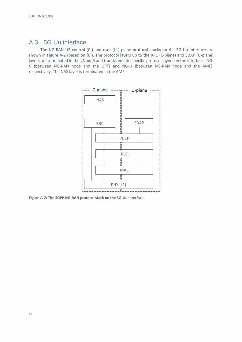
EDITION [01.00]
66
A.3 5G Uu interface The NG-RAN UE control (C-) and user (U-) plane protocol stacks on the 5G-Uu interface are
shown in Figure A-2 (based on [6]). The protocol layers up to the RRC (C-plane) and SDAP (U-plane) layers are terminated in the gNodeB and translated into specific protocol layers on the interfaces NG-C (between NG-RAN node and the UPF) and NG-U (between NG-RAN node and the AMF), respectively. The NAS layer is terminated in the AMF.
Figure A-2: The 3GPP NG-RAN protocol stack on the 5G-Uu interface.
PHY (L1)
RRC
NAS
SDAP
C-plane U-plane
MAC
RLC
PDCP

DROC2OM - 763601 - D4.1 Cellular LTE/5G system concepts to provide optimal support for both terrestrial communications and high reliability UAS data links
67
Appendix B Performance evaluations in 3GPP Aerial Vehicle scenarios
B.1 3GPP scenarios The investigated network deployment layout for the 3GPP scenarios is depicted in Figure B-1.
The virtual cell borders are depicted to highlight the regular grid used to position the radio sites. The simulated network layout has been extended using the ‘wrap-around’ method, so the performance results are collected from an equivalent network area which is 7 times larger (7 x 19 sites x 3 sectors). The corresponding scenario modelling parameters are listed in Table B-1.
The aerial vehicles were deployed with an average density to 5 per sector, which yields the spatial densities of approximately 5.78 AVs/ km2 and 69.3 AVs/ km2 in the RMa and UMa scenarios, respectively.
Figure B-1: The 3GPP Rural Macro (ISD=1732 m) radio network deployment layout with 19 sites, 3 sectors each. The 3GPP Urban Macro deployment has the same layout, with ISD = 500 m. Radio site locations and sector (cell) orientations are depicted.

EDITION [01.00]
68
Parameter Value
Carrier frequency RMa: 10 MHz in 700 MHz band
UMa: 20MHz in 2000 MHz band
Number of sectors (cells) and geographical area
RMa: 7*57 sectors, 345.5 km2
UMa: 7*57 sectors, 28.8 km2
ISD RMa: 1732m
Uma: 500m
BS antenna height RMa: 35m
UMa: 25m
BS antenna down-tilt RMa: 6 degrees
UMa: 10 degrees
AV UE height 20m, 50m, 100m, 300m
Terrestrial UE height 1.5 m
AV UE velocity 30 km/h, 160 km/h (linear flight path, at constant AV UE height)
Terrestrial UE velocity 30 km/h (linear path, at constant Terrestrial UE height)
Traffic model Downlink (forward link, network-to-AV):
- Terrestrial UEs: FTP model 3 with 0.5 MB buffer and packet inter-arrival time set for approx. 40% resource utilisation (cell load). - AV UEs: Command and control traffic model with 100 kbits buffer size and 100ms arrival rate.
Uplink (reverse link, AV-to-network):
- Terrestrial and AV UEs: Full buffer, time-burstiness follows downlink.
Number of AVs In average, 15 UEs (AV & Terrestrial) per sector and:
a) Reference, Case 1: 0 AVs (all terrestrial UEs)
b) UAV, Case 5: 5 AVs per sector (10 terrestrial UEs per sector), i.e. 5.78 AVs/ km
2 in RMa and 69.3 AVs/ km
2 in UMa
LOS/NLOS Dynamic; determined based on 2-D correlation distance and UE speed, for each UE towards each sector and subject to the RAN1 LOS probability channel model assumption. Path loss models specified by 3GPP RAN1.
MR triggering 3GPP A3 event
RLF triggering -8dB (SINR)
Simulation time 90 seconds (+10 seconds warm up time)
Resource allocation Terrestrial UE: Equal resources (all served UEs are scheduled)
Aerial UEs: Minimum required resources
Table B-1: Mobility simulation assumptions for 3GPP Rural Macro (RMa) and Urban Macro (UMa) scenarios [15] [16] [17].

DROC2OM - 763601 - D4.1 Cellular LTE/5G system concepts to provide optimal support for both terrestrial communications and high reliability UAS data links
69
B.2 Baseline performance results in 3GPP scenarios
In this section we present a summary of the performance results, some extensively discussed in references [15] [16] [17]. The traffic load (downlink) was set to approx. 40 % and determined by the packet arrival rate of the terrestrial UEs.
The downlink (forward link, network-to-*) and uplink (reverse link, *-to-network) SINR and throughput results for both AVs – Figure B-2 and Figure B-4 – and terrestrial UEs – Figure B-3 and Figure B-5 – are included here for completeness. The performance of the terrestrial UEs is presented separately vs. UAV penetration, UAV height and UAV speed. The radio mobility performance KPIs (HO, RLF, Qout) for the terrestrial UEs is not depicted in Figure B-3 and Figure B-5, and it is approximately a factor 10x better compared to the best performance of the UAVs, regardless of the presence of the UAVs.
Baseline radio mobility results for 3GPP Rural Macro scenario
Figure B-2: Baseline radio mobility performance of Aerial Vehicles in the 3GPP Rural Macro scenario.

EDITION [01.00]
70
Figure B-3: Baseline radio performance of Terrestrial UEs in the 3GPP Rural Macro scenario. The left most bar in each plot corresponds to the scenario without AVs, i.e. with only Terrestrial UEs.
Main conclusions for baseline 3GPP Rural Macro scenario
The average UAV DL SINR and Throughput are significantly impacted by the UAV flight height; at heights above 50 m the target average throughput of 200 Kbps cannot be reached due to very high downlink radio interference.
The average UAV UL SINR and Throughput are significantly impacted by the UAV flight height; at heights above 100 m the target average throughput of 200 Kbps cannot be reached due to very high uplink radio interference.
For the high UAV flight speeds of 160 km/h, the increased downlink radio interference also impacts the mobility performance KPIs, and significantly increased number of RLF is observed at UAV flight heights above 50 m.
The outage probability is significantly increased for UAV flight heights above 20 m, and strongly depends also on the UAV flight speed; the 99.9 % radio connectivity availability cannot be reached, regardless of the UAV flight height.
No AV
No AV
No AV

DROC2OM - 763601 - D4.1 Cellular LTE/5G system concepts to provide optimal support for both terrestrial communications and high reliability UAS data links
71
The penetration of UAVs (1 or 5 per cell) has minor impact on the downlink/uplink radio performance results; this is due to the relatively high(er) traffic load conditions generated by the terrestrial UEs.
The downlink performance (throughput and outage) of the terrestrial UEs is not significantly impacted by the presence of the UAVs.
The uplink throughput performance of the terrestrial UEs decreases for higher number for UAVs and UAV flight heights above 20 m.
Baseline radio mobility results for 3GPP Urban Macro scenario
Figure B-4: Baseline radio mobility performance of Aerial Vehicles in the 3GPP Urban Macro scenario.

EDITION [01.00]
72
Figure B-5: Baseline radio performance of Terrestrial UEs in the 3GPP Urban Macro scenario. The left most bar in each plot corresponds to the scenario without AVs, i.e. with only Terrestrial UEs.
Main conclusions for baseline 3GPP Urban Macro scenario
The average UE DL SINR and Throughput are significantly impacted by the UAV flight height; at heights above 20 m the target average throughput of 200 kbits/s cannot be reached due to very high radio interference.
The average UE UL SINR and Throughput are significantly impacted by the UAV flight height; at heights above 20 m the target average throughput of 200 kbits/s cannot be reached due to very high uplink radio interference.
For the high UAV flight speeds of 160 km/h, the increased radio interference also impacts the mobility performance KPIs, and significantly increased number of RLF is observed at UAV flight heights above 20 m.
The outage probability is significantly increased for UAV flight heights above 20 m, and strongly depends also on the UAV flight speed; the 99.9 % radio connectivity availability cannot be reached, regardless of the UAV flight height.
No AV
No AV
No AV

DROC2OM - 763601 - D4.1 Cellular LTE/5G system concepts to provide optimal support for both terrestrial communications and high reliability UAS data links
73
The penetration of UAVs (1 or 5 per cell) has medium impact on the downlink/uplink radio performance results; this is likely due to the relatively high(er) traffic load conditions generated by the terrestrial UEs.
The downlink performance (throughput and outage) of the terrestrial UEs is not significantly impacted by the presence of the UAVs.
The uplink throughput performance of the terrestrial UEs is decreases for higher number for UAVs and UAV flight heights above 20 m.