Embed Size (px)
Citation preview

© DriveWorks Ltd All rights reserved 2011 | DriveWorksXpress Tutorial 2011 1
The Proven Design Automation Choice for SolidWorks
DriveWorksXpress Mobile Gantry Tutorial
for SolidWorks 2011
© DriveWorks Ltd All rights reserved 2011 | DriveWorksXpress Tutorial 2011 2
DriveWorksXpress
Mobile Gantry Tutorial
Introduction
Start by installing the Models to a NEW FOLDER on your C: Drive. You should call this folder C:\DriveWorksXpressMobileGantryFiles
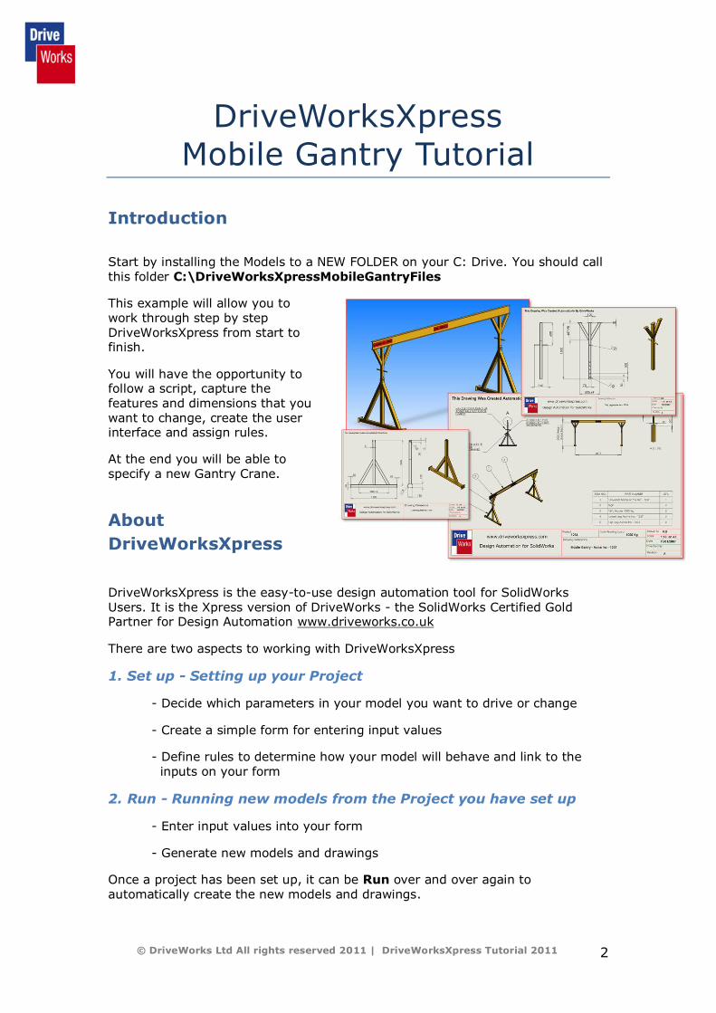
This example will allow you to work through step by step DriveWorksXpress from start to finish.
You will have the opportunity to follow a script, capture the features and dimensions that you want to change, create the user interface and assign rules.
At the end you will be able to specify a new Gantry Crane.
About
DriveWorksXpress
DriveWorksXpress is the easy-to-use design automation tool for SolidWorks Users. It is the Xpress version of DriveWorks - the SolidWorks Certified Gold Partner for Design Automation www.driveworks.co.uk
There are two aspects to working with DriveWorksXpress
1. Set up - Setting up your Project
- Decide which parameters in your model you want to drive or change
- Create a simple form for entering input values
- Define rules to determine how your model will behave and link to the inputs on your form
2. Run - Running new models from the Project you have set up
- Enter input values into your form
- Generate new models and drawings
Once a project has been set up, it can be Run over and over again to automatically create the new models and drawings.

© DriveWorks Ltd All rights reserved 2011 | DriveWorksXpress Tutorial 2011 3
Let’s get started Note - In this tutorial, we are going to be using SolidWorks 2011.
1. Launch SolidWorks (requires SolidWorks 2008 or later)
2. Launch DriveWorksXpress
The DriveWorksXpress 2011 Welcome Screen opens
The Welcome Screen provides you with feedback on the options available
to you, on the state of the project you are working on, or on the projects
you have already set up and that are ready to Run.
Note - DriveWorksXpress uses a database to store all the knowledge and
information needed to generate the outputs, clones and specifications. When you
open DriveWorksXpress for the very first time it creates a default database to
store your work called driveworksxpress.mdb.
The DriveWorksXpress Welcome screen always displays the Folder Path
and File Name of the active database.

© DriveWorks Ltd All rights reserved 2011 | DriveWorksXpress Tutorial 2011 4
The Welcome Screen also displays feedback on options available;
Create/Change Database
When DriveWorksXpress is launched without a database
loaded, the only options are to use the default database OR to
create a new one.
Add/Edit Models
This is only enabled once a database has been selected.
Run Models
This is only enabled once you have completed the
Administration/Set up of your project. You can then generate
new models using the Input form you have created, and based
on the parameters you have already captured and the rules you
have assigned rules.
For this exercise we will create a new database.
3. Create a New Database
Check the Radio Button against Create/Change database
Click Next
A Windows dialog box appears
Browse to where you want to create your new database (.mdb file)
C:\DriveWorksXpressMobileGantryFiles
For this exercise - name the database MobileGantryExample
Type the New File Name into the File Name Field and click Open
NOTE: Database Names must be unique.
If a name is not unique a warning message will appear advising that an existing
database will be overwritten. You may choose YES or NO to overwrite.
NOTE: Once you start using DriveWorksXpress regularly you may choose to store
multiple projects in a single database or in different databases.
© DriveWorks Ltd All rights reserved 2011 | DriveWorksXpress Tutorial 2011 5
4. Add your SolidWorks Models to DriveWorksXpress
DriveWorksXpress lets you create variants of your CAD assemblies, parts
and drawings. To do this you need to open your CAD file and add the
relevant models to DriveWorksXpress.
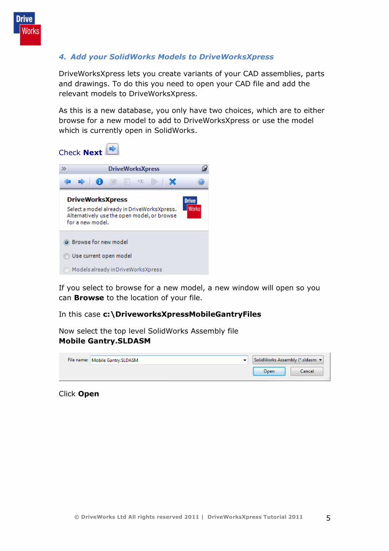
As this is a new database, you only have two choices, which are to either
browse for a new model to add to DriveWorksXpress or use the model
which is currently open in SolidWorks.
Check Next
If you select to browse for a new model, a new window will open so you
can Browse to the location of your file.
In this case c:\DriveworksXpressMobileGantryFiles
Now select the top level SolidWorks Assembly file
Mobile Gantry.SLDASM
Click Open

© DriveWorks Ltd All rights reserved 2011 | DriveWorksXpress Tutorial 2011 6
5. Capture – Select which models you want to drive
DriveWorksXpress now displays the captured models for the open
assembly.
NOTE - The Model will now also be open and visible in SolidWorks alongside the
DriveWorksXpress wizard
Click on the „Captured Assembly Structure‟ tab which is visible at the
bottom of the DriveWorksXpress task pane.
NOTE – It is possible for these tabs to be dragged and compressed into one line
in order to create more work space in DriveWorksXpress. So don‟t worry if you
don‟t see the tabs displayed in the image above. It is possible that you may see
the following:
Click the + symbol by the Assembly to expand / collapse the tree.
Select the parts/assemblies that you want DriveWorksXpress to control by
checking the box next to each item.
The top level assembly (Mobile Gantry) will already be checked.
For this exercise check the remaining models: -
Universal Beam Leg

© DriveWorks Ltd All rights reserved 2011 | DriveWorksXpress Tutorial 2011 7
5.1 Capture - Dimensions and Features
DriveWorksXpress lets you capture specific Dimensions and Features so
that you can apply rules and / or so you can specify new models based on
the original criteria using your own input forms.
A parameter is captured by selecting the „Captured Models‟ tab and then
double clicking on the model name that the parameter exists in from the
tree view.
Once the model has been double clicked, it will open up in SolidWorks.
Click on the „Dimensions and Features‟ tab
Follow the steps below which will guide you through each parameter that
is to be captured for this Mobile Gantry Example.

© DriveWorks Ltd All rights reserved 2011 | DriveWorksXpress Tutorial 2011 8
Capture Universal Beam
Double click on the Universal Beam in the „Captured Models‟ tab and then
select the „Dimensions and Features‟ tab.
Capture the Length of the Universal Beam
In the SolidWorks Feature Manager double click the icon of the feature
that contains the dimension to be captured (for the Length it is the plane
named Right End plane). The dimension will appear on the model.
Select the dimension from the model (by clicking on the dimension value).
Enter a New DriveWorks Name
This can be something more meaningful e.g. Beam Length
Click Add
The captured parameter will also now appear in the Parameter list under
Dimensions and Features in the DriveWorks task pane.
The SolidWorks Name of the
dimension will appear as
Address in the DriveWorks
task pane.

© DriveWorks Ltd All rights reserved 2011 | DriveWorksXpress Tutorial 2011 9
Next Capture the Section Height of the Universal Beam.
In the SolidWorks Feature Manager double click the feature that contains
the dimension to be captured (for the Section Height it is the Base
Extrude). The section dimension will appear on the model.
Click on the dimension and then, in the DriveWorksXpress task pane,
enter a new name – Beam Height.
Capture the Leg model
Double click the Leg from the tree view in the „Captured Models‟ tab.
Capture the height of the Leg.
In the SolidWorks Feature Manager double click the feature that contains
the dimension to be captured (for the Leg height it is in the sketch Lower
Layout).
The Leg height dimension will appear on the model.
Click on the dimension that controls the height and, in the Dimensions
and Features tab, enter a new DriveWorks Name –Leg Height

© DriveWorks Ltd All rights reserved 2011 | DriveWorksXpress Tutorial 2011 10
Click Add.
Next Capture the Minimum Overlap
Dimension.
Give this a DriveWorks Name Minimum
Overlap.
Next Capture the Inner Diagonal Feature.
The overall width of the gantry may also affect whether or not we need all
the supporting members. DriveWorksXpress can control the suppression
state of sketches, planes, features, folders etc. and can also delete them
from the model. In this example we have a folder with features in it. Using
rules, we can control whether we have these features or not.
Select the feature named Inner
Diagonal from the SolidWorks Feature
Manager.
The feature name will appear in the
Dimensions and Features tab. Enter a
new DriveWorks name Inner
Diagonal.
Click Add.

© DriveWorks Ltd All rights reserved 2011 | DriveWorksXpress Tutorial 2011 11
5.2 Capture - Custom Properties
DriveWorksXpress can also drive
values to Custom Properties:
Select the Captured Models tab and
double click on the Mobile Gantry
assembly.
Select the Custom Properties TAB to
start capturing Custom Properties.
These are useful for linking to
annotations in drawings to drive
text on drawing borders or notes.
They are also useful for acting as
placeholders where complex rules
can be broken down into more
manageable portions.
Any existing Custom Properties will
appear in the list which is now
displayed.
In this example these are
Drawn by
Safe Working Load
Project
We are going to use all of these
custom properties. Check the boxes
next to each property in order to
capture it.

© DriveWorks Ltd All rights reserved 2011 | DriveWorksXpress Tutorial 2011 12
The File Path of the drawing
now appears in the drawing
pane so that you can check
you have the correct
drawing.
5.3 Capture Drawings
As well as generating new models, DriveWorksXpress can also produce
new drawings of the model. This is done by associating a previously
produced template drawing of the master model.
To add a drawing, open the Mobile Gantry top level assembly using the
tree view in the Captured Models tab and then browse to the Drawings
and Configurations tab. Browse to the location of the template drawing
C:\DriveWorksXpressMobileGantryFiles
Select Mobile Gantry.SLDDRW and click Open
It is also possible to add one part drawing per part.
Add the template drawings for the following parts.
Universal Beam Universal Beam.SLDDRW
Leg leg.SLDDRW
© DriveWorks Ltd All rights reserved 2011 | DriveWorksXpress Tutorial 2011 13
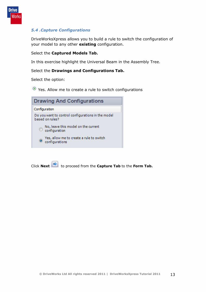
5.4 .Capture Configurations
DriveWorksXpress allows you to build a rule to switch the configuration of
your model to any other existing configuration.
Select the Captured Models Tab.
In this exercise highlight the Universal Beam in the Assembly Tree.
Select the Drawings and Configurations Tab.
Select the option:
Yes. Allow me to create a rule to switch configurations
Click Next to proceed from the Capture Tab to the Form Tab.
© DriveWorks Ltd All rights reserved 2011 | DriveWorksXpress Tutorial 2011 14
6 Input Form
You now need to create an input form for entering the values for your new
parts and drawings. This form can be used again and again to specify and
generate all the parts and drawings based on the rules you set and values
you enter.
Start by adding the input controls
You can use the following form controls types in DriveWorksXpress;
Text Box, Numeric Text Box, Drop Down, Spin Button, Check Box
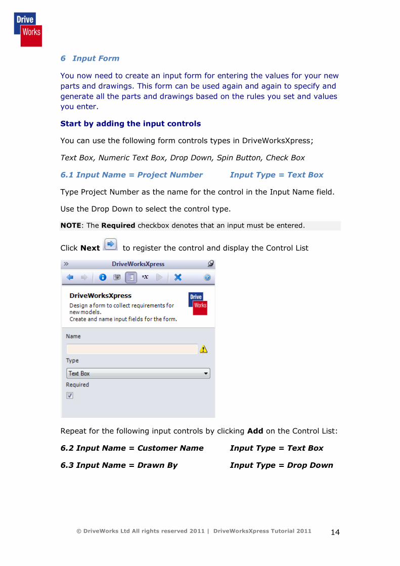
6.1 Input Name = Project Number Input Type = Text Box
Type Project Number as the name for the control in the Input Name field.
Use the Drop Down to select the control type.
NOTE: The Required checkbox denotes that an input must be entered.
Click Next to register the control and display the Control List
Repeat for the following input controls by clicking Add on the Control List:
6.2 Input Name = Customer Name Input Type = Text Box
6.3 Input Name = Drawn By Input Type = Drop Down

© DriveWorks Ltd All rights reserved 2011 | DriveWorksXpress Tutorial 2011 15
Enter the values in the panel. Hit return after value to place on next line.
6.4 Input Name = Safe Working Load Input Type = Drop Down
Enter the following drop down values:
500 Kg
1000 Kg
1500 Kg
NOTE: These values will drive a configuration in the Universal Beam. Ensure the
entries are identical to those shown (i.e. space between 0 and K, upper case K,
no spaces at front or end of each text string.
6.5 Input Name = Opening Height Input Type = Spin Button
A spin button requires additional properties setting. These dictate the
minimum and maximum values that can be selected and the increments
the values will increase and decrease:
Enter a min value of 1500
Enter a max value of 2500 Enter an increment value of 50
NOTE: The units that DriveWorksXpress drives the models to are the document
units the model has been set to. This example uses metric units.
6.6 Input Name = Opening Width Input Type = Numeric
Text Box
A Numeric Text Box allows limits to be set that the entered value is
evaluated against. A warning will appear if the limits are exceeded.
Enter a minimum value of 1500
Enter a maximum value of 4000
NOTE: Once created you can move controls up and down, edit, delete and test
them. Fields which have not been validated remain red.
Click Test and enter test values to check that items such as spin buttons
and drop downs have the information you require. You can even set
default values.
Click Next to proceed to the Rules Tab to set up & build your rules.
© DriveWorks Ltd All rights reserved 2011 | DriveWorksXpress Tutorial 2011 16
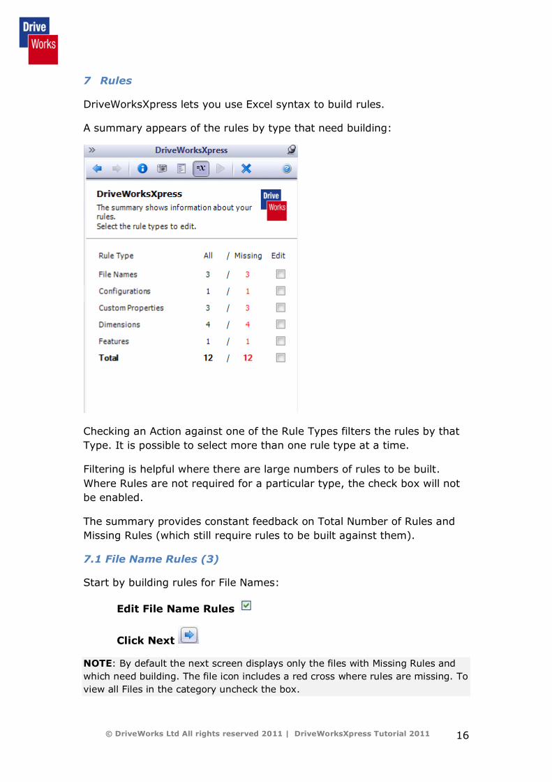
7 Rules
DriveWorksXpress lets you use Excel syntax to build rules.
A summary appears of the rules by type that need building:
Checking an Action against one of the Rule Types filters the rules by that
Type. It is possible to select more than one rule type at a time.
Filtering is helpful where there are large numbers of rules to be built.
Where Rules are not required for a particular type, the check box will not
be enabled.
The summary provides constant feedback on Total Number of Rules and
Missing Rules (which still require rules to be built against them).
7.1 File Name Rules (3)
Start by building rules for File Names:
Edit File Name Rules
Click Next
NOTE: By default the next screen displays only the files with Missing Rules and
which need building. The file icon includes a red cross where rules are missing. To
view all Files in the category uncheck the box.
© DriveWorks Ltd All rights reserved 2011 | DriveWorksXpress Tutorial 2011 17
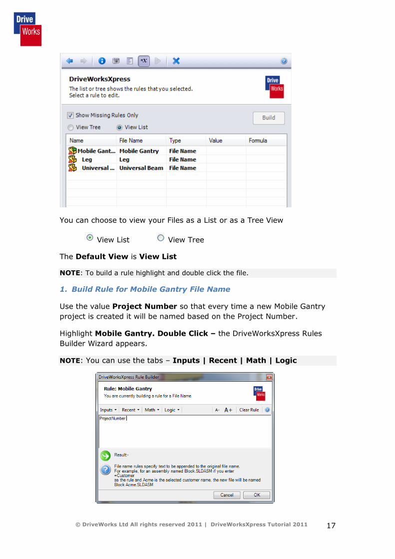
You can choose to view your Files as a List or as a Tree View
View List View Tree
The Default View is View List
NOTE: To build a rule highlight and double click the file.
1. Build Rule for Mobile Gantry File Name
Use the value Project Number so that every time a new Mobile Gantry
project is created it will be named based on the Project Number.
Highlight Mobile Gantry. Double Click – the DriveWorksXpress Rules
Builder Wizard appears.
NOTE: You can use the tabs – Inputs | Recent | Math | Logic
© DriveWorks Ltd All rights reserved 2011 | DriveWorksXpress Tutorial 2011 18
NOTE –The items listed in Inputs are all the controls that you have created for
entering inputs on your form.
Map these inputs to your parameters to build your rules.
Click on the Inputs Value Project Number
The effect of this will be to append the Project Number to the Mobile
Gantry file name when you run your new specification.
Click Ok to return to the Rules Summary List
Continue by adding rules for the remaining 2 File Names
NOTE: In Rule Building the symbol & is used to link strings.
2. Build Rule for the Universal Beam File Name
Build the rule as follows:
OpeningWidth & " Wide - " & SafeWorkingLoad & " Safe Working
Load"
If the value entered on your form for Opening Width is 2000 and the Safe
Working Load is 500 Kg, the result of the rule for the file name of the
Beam Assembly will be 2000 Wide - 500 Kg Safe Working Load
NOTE - You can add and use Quick Text for frequently used text strings for
example "wide", "high", "Opening Width" and so on.
Just add your text to the Recent Menu by selecting Change Quick Text.
3. Build Rule for Leg File Name
Build the rule as follows:
As DriveWorks can reuse files previously created, you can build a library
of standards.
Use the height parameters to build up a text string as a means of
identifying the file.
Use the Original File Name, then add the Openingheight & "high".
The rule result is OpeningHeight & " high"
Click Previous to return to Rules Summary.

© DriveWorks Ltd All rights reserved 2011 | DriveWorksXpress Tutorial 2011 19
7.2 Build Configurations Rule (1)
Un-check File Names Rules
Edit Configuration Rules
Click Next
DriveWorksXpress does not create new configurations but it can be set
to drive an existing file. The Universal Beam model uses
configurations.
1. Build Rule for Universal Beam Configuration
Use the input SafeWorkingLoad as the rule.
Click Previous to return to Rules Summary.
7.3 Custom Property Rules (3)
Un-check Configurations Rules
Edit Custom Properties Rules
Click Next
1. Build Rule for Drawn by
Use the input value Drawn by
2. Build Rule for Safe Working Load
Use the input value Safe Working Load
3. Build Rule for Project
Use the input value Project Number
Click Previous to return to the Rules Summary.
7.3 Build Rules for Dimension (4)
Un check Custom Properties Rules
Edit Dimension Rules
Click Next
© DriveWorks Ltd All rights reserved 2011 | DriveWorksXpress Tutorial 2011 20
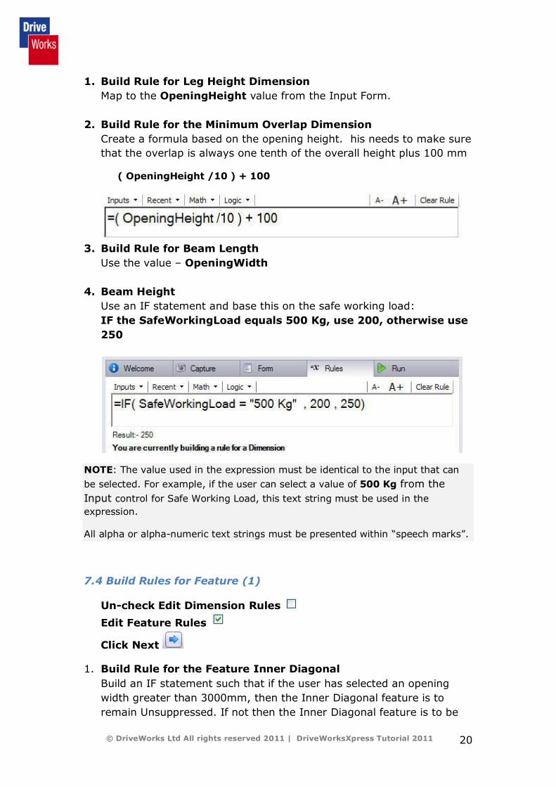
1. Build Rule for Leg Height Dimension
Map to the OpeningHeight value from the Input Form.
2. Build Rule for the Minimum Overlap Dimension
Create a formula based on the opening height. his needs to make sure
that the overlap is always one tenth of the overall height plus 100 mm
( OpeningHeight /10 ) + 100
3. Build Rule for Beam Length
Use the value – OpeningWidth
4. Beam Height
Use an IF statement and base this on the safe working load:
IF the SafeWorkingLoad equals 500 Kg, use 200, otherwise use
250
NOTE: The value used in the expression must be identical to the input that can
be selected. For example, if the user can select a value of 500 Kg from the
Input control for Safe Working Load, this text string must be used in the
expression.
All alpha or alpha-numeric text strings must be presented within “speech marks”.
7.4 Build Rules for Feature (1)
Un-check Edit Dimension Rules
Edit Feature Rules
Click Next
1. Build Rule for the Feature Inner Diagonal
Build an IF statement such that if the user has selected an opening
width greater than 3000mm, then the Inner Diagonal feature is to
remain Unsuppressed. If not then the Inner Diagonal feature is to be
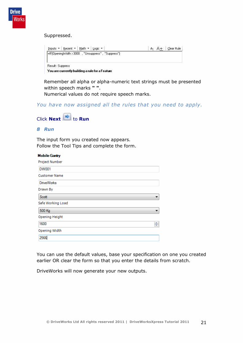
© DriveWorks Ltd All rights reserved 2011 | DriveWorksXpress Tutorial 2011 21
Suppressed.
Remember all alpha or alpha-numeric text strings must be presented
within speech marks " ".
Numerical values do not require speech marks.
You have now assigned all the rules that you need to apply.
Click Next to Run
8 Run
The input form you created now appears.
Follow the Tool Tips and complete the form.
You can use the default values, base your specification on one you created
earlier OR clear the form so that you enter the details from scratch.
DriveWorks will now generate your new outputs.

© DriveWorks Ltd All rights reserved 2011 | DriveWorksXpress Tutorial 2011 22
NOTE: For further help see the Help files within DriveWorksXpress.
If you want to create
new variations, just fill
out the form again, and
again and again.