Embed Size (px)
Citation preview
Page 1 of 9
Made Better In The USA by: Miltronics Manufacturing, Inc 95 Krif Road Keene, NH 03431 www.miltronics.com
Phone: (603) 352-3333 Sales: (800) 828-9089 Fax: (603) 352-4444
www.drivewayalert.com [email protected]
Driveway Alert® Systems Rev. 11-15-2017 Copyright © 2014 Miltronics Manufacturing, Inc.
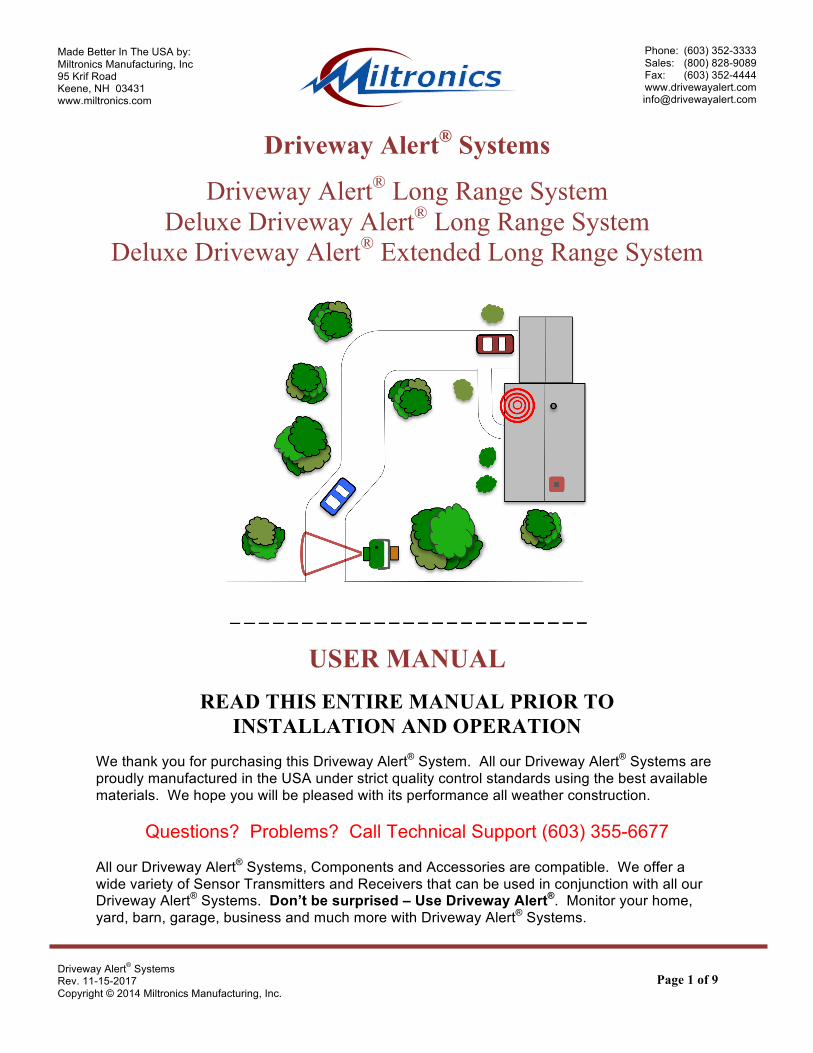
Driveway Alert® Systems
Driveway Alert® Long Range System Deluxe Driveway Alert® Long Range System
Deluxe Driveway Alert® Extended Long Range System
USER MANUAL
READ THIS ENTIRE MANUAL PRIOR TO INSTALLATION AND OPERATION
We thank you for purchasing this Driveway Alert® System. All our Driveway Alert® Systems are proudly manufactured in the USA under strict quality control standards using the best available materials. We hope you will be pleased with its performance all weather construction.
Questions? Problems? Call Technical Support (603) 355-6677 All our Driveway Alert® Systems, Components and Accessories are compatible. We offer a wide variety of Sensor Transmitters and Receivers that can be used in conjunction with all our Driveway Alert® Systems. Don’t be surprised – Use Driveway Alert®. Monitor your home, yard, barn, garage, business and much more with Driveway Alert® Systems.

Page 2 of 9
Made Better In The USA by: Miltronics Manufacturing, Inc 95 Krif Road Keene, NH 03431 www.miltronics.com
Phone: (603) 352-3333 Sales: (800) 828-9089 Fax: (603) 352-4444
www.drivewayalert.com [email protected]
Driveway Alert® Systems Rev. 11-15-2017 Copyright © 2014 Miltronics Manufacturing, Inc.
DRIVEWAY ALERT® SYSTEMS FAMILY
The Only Original Driveway Alert® Systems Home and Yard Alert® Multi-Channel Systems Campers Alert® and Hunters Alert® Portable Receivers Air-Hose AlertTM – Old Gas Station Style Pressure Tube Sensor Transmitter Magnetic Switch Transmitter for Windows, Doorways and more Trip Wire Transmitter for Perimeters or Large Valuable Items High Water and Low Water Sensor Transmitters Push Button Transmitters, Relay Transmitters ISA AlertTM Systems for those in need Mail Delivery Sensor/Transmitters Thermal AlertTM Systems Hard Wired Systems
DRIVEWAY ALERT® SYSTEMS AVAILABLE ACCESSORIES Sound and Light: Siren, Chime, Buzzers, Fire Bell and Strobe Light More: Event Counter, Relay Module, Relay Outlets, Cables and Power Options
LIMITED LIFETIME WARRANTY Miltronics Manufacturing, Inc. provides a lifetime warranty on parts and two years on labor. Miltronics guarantees all parts of this product to the original owner against manufacturing or parts defects. This warranty shall not apply to defects resulting from improper installation or use, unauthorized repair and consequent damage, abuse, modification, using in a fashion other than intended, fire, flood or act of God, or on which serial numbers have been altered, defaced or removed. If your unit cannot be repaired, Miltronics may replace it with new or reconditioned merchandise. Miltronics will assume no liability for commercial loss or any kind of damage resulting from malfunction of the product, or resulting from its unsuitable use. In any event liability shall not exceed the original purchase price. WARRANTY REPAIR POLICY: The entire system requiring warranty repair must be returned to Miltronics, by prepaid freight, with proof of purchase, a brief description of the problem, your email address and a daytime phone number to contact you if necessary. Beginning with year three of this warranty a minimal labor fee will apply. A handling fee will apply to products sent to Miltronics that are not covered under warranty.
CUSTOMER RETURN POLICY Return of unused product must be done within 30 days of purchase. Shipping and handling charges are not refundable. A 20% restock fee may apply.
MILTRONICS Manufacturing, Inc. 95 Krif Road, Keene, NH 03431 Sales & Info 1-888-NH-ALERT
Technical Support 1-603-355-6677

Page 3 of 9
Made Better In The USA by: Miltronics Manufacturing, Inc 95 Krif Road Keene, NH 03431 www.miltronics.com
Phone: (603) 352-3333 Sales: (800) 828-9089 Fax: (603) 352-4444
www.drivewayalert.com [email protected]
Driveway Alert® Systems Rev. 11-15-2017 Copyright © 2014 Miltronics Manufacturing, Inc.
DRIVEWAY ALERT® SYSTEM - KIT CONTENTS: Driveway Alert® Receiver, Receiver Power Cable with Transformer and Hook & Loop Mounting Fasteners Driveway Alert® Infra Red Sensor Transmitter, Metal Mounting Bracket with Screws and a 9-Volt Battery INFRA RED SENSOR TRANSMITTER OPERATION AND INSTALLATION: The infra red sensor is positioned behind the round IR filter lens. It has a horizontal detection angle of 40 degrees and a detection range of over 30 feet. See diagram below. The optimum target range is 10 to 15 feet from the Sensor Transmitter. The infra red sensor detects vehicles, intruders, etc., by sensing their heat and motion. When a vehicle or large warm object moves through the detection zone, the Infra Red Sensor Transmitter detects the intrusion and transmits a signal to the receiver. When the battery’s voltage has dropped below the sensor’s required operating voltage, transmissions are sent to the Receiver until the battery voltage becomes too low to transmit.
First, install a high quality 9-volt alkaline battery in the compartment located in back of the sensor case. Securely close the battery cover. The Battery will last about six months under normal use. Mount the sensor approximately 2 to 2.5 feet above the ground to a tree, wooden post or side of a building. A Metal Mounting Bracket and Mounting Screws are provided. Refer to the System Set-Up on page 7. Perform the “Walk Test” (see page 5) prior to mounting permanently. The Sensor Transmitter’s IR Lens and infra red sensor must have an unobstructed view of the detection area that is free of plants, shrubs and branches. Take care not to touch the Lens or allow the Lens to get damaged. Straighten and extend the flexible antenna straight upward. Some objects may not be detected if the sensor is placed too high or too low. Adjusting may be required prior to calling for technical support. Keep the sensor as close to the edge of the driveway as possible. The sensor should be strategically located so that it detects objects moving across detection zone. Do not mount the sensor facing the sun, bodies of water or any large reflective objects. This causes variations in the temperature pattern "seen" by the sensor windows and may cause false alarms or damage the lens. PLEASE NOTE: A shorter transmission range may occur when the outside temperature falls below 20 degrees F. due to a natural drop in battery voltage. Lower sensitivity may occur during periods of heavy fog, rain or snow. This is due to the moisture diffusing the infra red energy. The Sensor Transmitters are completely weatherproof and will operate to -40 degrees Fahrenheit.

Page 4 of 9
Made Better In The USA by: Miltronics Manufacturing, Inc 95 Krif Road Keene, NH 03431 www.miltronics.com
Phone: (603) 352-3333 Sales: (800) 828-9089 Fax: (603) 352-4444
www.drivewayalert.com [email protected]
Driveway Alert® Systems Rev. 11-15-2017 Copyright © 2014 Miltronics Manufacturing, Inc.
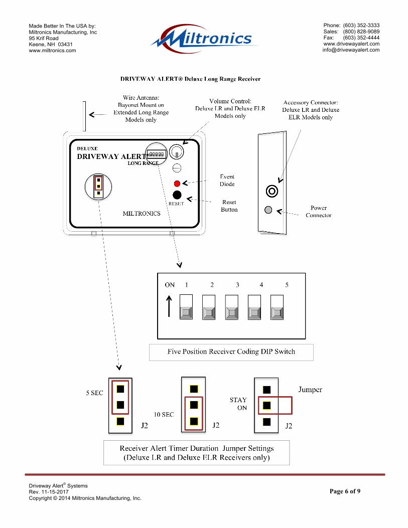
TRANSMITTER CODING ADJUSTMENT: The system coding is factory pre-set and should be adjusted only in the event of interference from another source. Remove the battery cover to access the Five Position Coding DIP-Switch. The DIP-Switch settings in the Sensor/Transmitter must match the settings in the Receiver. See diagram below. SENSOR SENSITIVITY ADJUSTMENT: The Infra Red Sensor is located in the Transmitter Case behind the Infra Red Lens. There is a two-position DIP-switch to adjust the Sensor’s Infra Red Sensitivity. This is factory pre-set and should not be adjusted without consulting with Technical Support. In typical installations, changing these settings will cause extremely erratic system behavior. See diagram below.

Page 5 of 9
Made Better In The USA by: Miltronics Manufacturing, Inc 95 Krif Road Keene, NH 03431 www.miltronics.com
Phone: (603) 352-3333 Sales: (800) 828-9089 Fax: (603) 352-4444
www.drivewayalert.com [email protected]
Driveway Alert® Systems Rev. 11-15-2017 Copyright © 2014 Miltronics Manufacturing, Inc.
RECEIVER OPERATION AND INSTALLATION: Plug the transformer into a 110-volt, indoor outlet. Stand the Receiver up or mount it to the wall with the included hook and loop fasteners. Extend the wire antenna straight upward (Deluxe Extended Long Range Model; attach the rigid bayonet mount antenna to the connector on the Receiver). The Receiver will sound the alert and the Event Diode will illuminate when the sensor is activated and the signal is received. The alert sound resets itself after five seconds and the Event Diode remains on. Pressing the Reset Button after an event will shut off the Event Diode. The Alert Tone will continue to alert you with every intrusion. The Alert Tone Duration is factory pre-set for five seconds. By changing the on board Jumper settings, you can change the tone duration to 10 seconds or constant on (Deluxe LR and Deluxe ELR Receivers only). See diagram on page 6. When in the constant on mode, the Alert Tone and Event Diode can be reset by pressing the Reset Button. The volume control (Deluxe LR and Deluxe ELR Receivers Only) is used to change the sound level of the Alert Tone.
Driveway Alert® Long Range Deluxe Driveway Alert® Long Range Deluxe Driveway Alert® Extended LR The Deluxe Long Range and Deluxe Extended Long Range Receiver Models come equipped with an accessory jack for the easy addition of accessories (sold separately), adding to the versatility of the Deluxe systems. Carefully align and plug your Accessory plug into the jack on the Receiver and ensure you feel two “clicks” indicating proper engagement. The accessory output supports 12-volt DC accessories with a maximum current draw of 300-mAmp. In unobstructed space, the reception range can reach up to 1,500 feet (up to 2,500 feet for Extended Long Range models). Range may be reduced by certain obstructions such as; metal buildings, dense woods, brick walls, etc. For maximum range, locate the receiver in an area in your home with some direct visibility to the sensor. In order to minimize interference, it may be necessary to plug the Driveway Alert® Receiver into an electrical circuit with no other operating appliances. Hard-wired Sensor Transmitters and Receivers are available when transmission is not possible or practical. RECEIVER CODING ADJUSTMENT: The system coding is factory pre-set and should be adjusted only in the event of interference from another source. Prior to adjustment, unplug the 110-volt transformer from the power outlet and disconnect power cord from the Receiver. Remove the volume control knob and cover to access the Five Position Coding DIP Switch. See diagram on page 6. The DIP-Switch settings in the Receiver must match the settings in the Sensor/Transmitter. Replace cover and volume knob prior to operation. WALK TEST: After setting up your system, perform a "Walk Test” to ensure proper system operation. Walk and drive through the detection area and have someone listen for the receiver to sound. The Sensor/Transmitter and/or the Receiver can then easily be repositioned if not performing as desired. See the FCC Statement at the end of this Manual for more information.
Page 6 of 9
Made Better In The USA by: Miltronics Manufacturing, Inc 95 Krif Road Keene, NH 03431 www.miltronics.com
Phone: (603) 352-3333 Sales: (800) 828-9089 Fax: (603) 352-4444
www.drivewayalert.com [email protected]
Driveway Alert® Systems Rev. 11-15-2017 Copyright © 2014 Miltronics Manufacturing, Inc.

Page 7 of 9
Made Better In The USA by: Miltronics Manufacturing, Inc 95 Krif Road Keene, NH 03431 www.miltronics.com
Phone: (603) 352-3333 Sales: (800) 828-9089 Fax: (603) 352-4444
www.drivewayalert.com [email protected]
Driveway Alert® Systems Rev. 11-15-2017 Copyright © 2014 Miltronics Manufacturing, Inc.
Driveway Alert® System Set-Up

Page 8 of 9
Made Better In The USA by: Miltronics Manufacturing, Inc 95 Krif Road Keene, NH 03431 www.miltronics.com
Phone: (603) 352-3333 Sales: (800) 828-9089 Fax: (603) 352-4444
www.drivewayalert.com [email protected]
Driveway Alert® Systems Rev. 11-15-2017 Copyright © 2014 Miltronics Manufacturing, Inc.
Driveway Alert® Systems Troubleshooting Guide: When your system is operating properly, there are three main functions being performed. First, the passive Infra Red Sensor detects a vehicle or other warm object passing through the detection zone. Second, once an object is detected, the Transmitter sends a signal. Third, the Receiver gets the transmitted signal from the Sensor Transmitter and activates the Alert Tone and the Event Diode at the Receiver. If your system is not working as expected, review this troubleshooting guide and keep in mind there are three different functions to consider. As you troubleshoot and alleviate various adverse conditions, it is best to have someone help you perform the Walk Tests. There are also two extremely important environmental issues that must be considered. First, as with all passive infra red devices, certain conditions and acts of nature may cause false alarms or reduced sensitivity. Reflective objects directing sunlight at the Sensor Transmitter Lens can cause false alarms. Certain weather conditions such as: heavy fog, rain or snow can diffuse an object’s infra red energy enough so that the object can not be detected. Second, and most important, many household appliances induce noise into the household electrical lines and outlets. In order to maximize the range between the Receiver and Transmitter, our Receivers are highly tuned and very sensitive. When possible, isolate the Receiver on its own circuit or a circuit that has minimal use by other devices. LED Lighting and LED TVs induce a tremendous amount of electrical noise into household circuits. Computers and motors also create a high level of electrical noise. Other wireless electronic devices, such as; garage door openers and Wi-Fi networks, can transmit wireless signals that interfere or create false alarms in your Driveway Alert® System. PROBLEM: My Receiver will not activate when objects pass through the sensor detection zone. CORRECT THE ADVERSE CONDITIONS THAT EXIST: The Battery in the Sensor Transmitter is not a new high quality alkaline battery. The Battery in the Sensor Transmitter is depleted below the voltage required to sense and transmit. The Sensor Transmitter’s detection zone is not clear of obstructions. The Sensor Transmitter is not mounted one to two feet from driveway edge. The Sensor Transmitter is not mounted so the Lens is 2 to 2 ½ feet about the driveway surface. The Sensor Transmitter is not pointed straight across the driveway. The Sensor Transmitter Lens is not perpendicular to the object’s travel. The Sensor Transmitter is either pointed upward or downward and not level. The Sensor Transmitter is out of range and the signal is too weak to be received. The Sensor Transmitter is very close to the Receiver. The transmitted signal does not have a clear path to the Receiver for maximum unobstructed reception. The transmitted signal is not propagating through the dense trees for maximum unobstructed reception. The transmitted signal is not propagating through dense earth, rock or cement. The Receiver is behind or shrouded by thick or dense walls. The Receiver is plugged into an outlet with other devices or appliances. The Receiver is plugged into the same circuit with other devices or appliances. The Receiver is obstructed and not placed near a window for maximum unobstructed reception. There is interference in the area and the system coding needs to be changed. PROBLEM: My Receiver activates when nothing passes through the sensor detection zone. CORRECT THE ADVERSE CONDITIONS THAT EXIST: The Battery in the Sensor Transmitter is not a new high quality alkaline battery. The Battery in the Sensor Transmitter is depleted below the voltage required to sense activity. The Sensor Transmitter is not securely mounted and is shaking or moving slightly. The sun is shining directly into the Sensor Transmitter Lens. The sun is reflecting off large reflective objects into the Sensor Transmitter Lens. Objects free to move in the wind (bushes, small trees, etc.) are in the sensor’s detection zone. PROBLEM: My Receiver is constantly activated. CORRECT THE ADVERSE CONDITIONS THAT EXIST: The Battery in the Sensor Transmitter is not a new high quality alkaline battery. The Battery in the Sensor Transmitter is depleted below the voltage required to sense activity. There is interference in the area and the system coding needs to be changed.
Still have problems or questions? Call Technical Support (603) 355-6677

Page 9 of 9
Made Better In The USA by: Miltronics Manufacturing, Inc 95 Krif Road Keene, NH 03431 www.miltronics.com
Phone: (603) 352-3333 Sales: (800) 828-9089 Fax: (603) 352-4444
www.drivewayalert.com [email protected]
Driveway Alert® Systems Rev. 11-15-2017 Copyright © 2014 Miltronics Manufacturing, Inc.
CAUTION: Changes or modifications not expressly approved by Miltronics could void the user's warranty and authority to operate this device. FCC STATEMENT: This device complies with part 15 of the FCC Rules. Operation is subject to the following two conditions: (1) This device may not cause harmful interference, and (2) This device must accept any interference received, including interference that may cause undesired operation. This equipment has been tested and found to comply with the limits for an intentional radiator pursuant to Part 15 of the FCC Rules. These limits are designed to provide reasonable protection against harmful interference in a residential installation. This equipment generates, uses, and can radiate radio frequency energy and if not installed and used in accordance with the instructions may cause harmful interference to radio communications. However, there is no guarantee that interference will not occur in a particular installation. If this equipment does cause interference to radio or television reception, which can be determined by turning the equipment off and on, the user is encouraged to try to correct the interference by one or more of the following measures: - Reorient or relocate the receiving antenna - Increase the separation between the equipment and receiver - Connect the equipment into an outlet on a circuit different from that to which the receiver is connected - Consult the dealer or an experienced radio/TV technician for help
Miltronics Manufacturing., Inc.
95 Krif Road, Keene, NH 03431 USA Sales: (800) 828-9089
Offices: (603) 352-3333 Fax: (603) 352-4444 [email protected]