Embed Size (px)
Citation preview

lable at ScienceDirect
Applied Ergonomics 41 (2010) 225–235
Contents lists avai
Applied Ergonomics
journal homepage: www.elsevier .com/locate/apergo
Driver–Vehicle–Environment monitoring for on-board driver support systems:Lessons learned from design and implementation
Angelos Amditis a,*, Katia Pagle a, Somya Joshi a, Evangelos Bekiaris b
a Institute of Communication and Computer Systems, Iroon Polytechniou St. 9, 15773 Athens, Greeceb Hellenic Institute of Transport (HIT), Centre for Research and Technology Hellas, 6th Km Charilaou, Thermi Road, PO Box 361, 57001 Thermi, Thessaloniki, Greece
a r t i c l e i n f o
Article history:Received 8 September 2008Received in revised form10 March 2009Accepted 13 March 2009
Keywords:Driver support systemsValidationDriver–Vehicle–Environment monitoring
* Corresponding author.E-mail addresses: [email protected] (A. Amditi
[email protected] (S. Joshi), [email protected] (E. Bekiaris).
0003-6870/$ – see front matter � 2009 Elsevier Ltd.doi:10.1016/j.apergo.2009.03.002
a b s t r a c t
This paper is presenting the efforts to implement in real time and for on-board applications a set ofDriver–Vehicle–Environment (DVE) monitoring modules based on the theoretical work done in DVEmodelling within the EC 6th FW co funded AIDE Integrated Project.
First the need for such an implementation will be discussed. Then the basic DVE modelling principleswill be introduced and analysed. Based on that and on the overview of the theoretical work performedaround the DVE modelling, the real time DVE monitoring modules developed in this project will bepresented and analysed. To do this the DVE parameters needed to allow the required functionalities willbe discussed and analysed. Special attention will be given to the use cases and scenarios of use for thereal time DVE modules. This allows the reader to understand the functionalities that these modulesenable in tomorrow’s vehicles that will integrate a large degree of automation supported by advancedintegrated and adaptive human machine interfaces (HMIs). The paper will also present examples of thefunctional and technical tests and validation results for some of the DVE modules. The paper willconclude with a discussion around the lessons learned about the design and implementation of suchsystems. This will include also the next steps and open issues for research in order for these systems tobecome standard modules in tomorrow’s vehicles.
� 2009 Elsevier Ltd. All rights reserved.
1. Introduction
Drivers are exposed to an increasing information flow providedby a number of on-board functions (not exclusively related to thedriving task) and, in the near future of the massive introduction ofdriver assistance systems (such as Advanced Driver AssistanceSystems, navigation systems, nomadic devices etc.). On the otherhand, the driver is not always capable of receiving and under-standing the messages that are given by the different functions.Major reasons include issues like the physiological state of thedriver (e.g. tired or absent minded), his/her profile (e.g. age, ordriving experience); but also the complex traffic environment thatrequires attention, and sometimes the external non-traffic relatedsolicitations such as road advertisements. In this context, severalquestions need to be answered: how to avoid the driveroverloading by a ‘‘disparate’’ information flow? What informationshould be delivered, when and how? How to avoid interference
s), [email protected] (K. Pagle),
All rights reserved.
between different pieces of information? And, on an even moregeneral level, how to avoid the negative impact of these informa-tion sources on the driving task? A recent study (Horberry et al.,2006) demonstrates the complexity of DVE factors on drivingperformance. In their paper it is shown that both in-vehicletasks impaired several aspects of driving performance, with theentertainment system distracter having the greatest negativeimpact on performance, and that these findings were relativelystable across different driver age groups and different environ-mental complexities.
The general goal of the AIDE Integrated Project was to generateknowledge and to develop methodologies as well as HumanMachine Interfaces technologies required for safe and efficientintegration of Advanced Driver Assistance Systems (ADAS), In-Vehicle Information Systems (IVIS) and Nomadic Devices (ND) intothe driving environment. As an ‘‘Adaptive’’ and ‘‘Integrated’’ infor-mation manager, AIDE should contribute to solve these problemsby implementing adaptive interface technologies to minimisedriver distraction taking into account the current state of the driver,the vehicle and their environment.
The perception of a given driving scenario and its impact on thedriver is considered for this context to be represented through the

Fig. 1. Logical interplay of Parameters, Variables and DVE model.
A. Amditis et al. / Applied Ergonomics 41 (2010) 225–235226
following triptych: the Driver–Vehicle–Environment (DVE) state.Several modules, called ‘‘DVE modules’’, have been defined with thepurpose of computing in real time a set of parameters needed forenabling the adaptive interface functions according to the AIDEdesign scenarios descriptions and the relevant criteria for HMIadaptation to certain driving conditions.
The DVE monitoring modules were designed to process thetraffic/environmental demand, the level of driving demand, thelevel of driver distraction (Cognitive Distraction–Visual Distrac-tion), the intent of the driver, and the driver’s physical impairment;the goal here is to determine which function’s messages should becommunicated to the driver under a particular circumstance.Non-driving task information and functions within this context willthus be prioritised based on how crucial the information is ata specific time, relative to the level of driving task demand takingalso into consideration the driver’s profile.
Within this context a recent study (Matthews, 2002) offersa transactional model of driver stress and fatigue, and its ergonomicapplication to designing vehicle systems for ‘stress-tolerance’.According to this study disturbances of subjective state arecontrolled by cognitive stress processes of appraisal and coping.Both personality factors and situational stressors may elicitmaladaptive patterns of cognition that generate subjective stresssymptoms, elicit potentially dangerous coping strategies, andinterfere with information-processing and attention to the task athand. Studies using a driving simulator were used here to explorethe behavioural consequences of several qualitatively differentforms of ‘stress’, that can be loosely labelled as anxiety, anger andfatigue.
This paper aims to describe and analyse the design principlesand concepts of the DVE modules as well as the various informa-tion and sensors that are necessary to implement them for on-board use. Each module is a separate application with its ownrequirements, specifications and architecture; it is considered asa unique entity in the DVE real time monitoring system. Thus, allmodules have been developed independently with well-definedinterfaces for data exchange, when necessary. In addition, all DVEmodules are complementary to each other and cover specificaspects of the different DVE monitoring requirements. In thisrespect the presence of all of them is crucial in an integratedadaptive HMI.
The development of the DVE modules has followed the theo-retical work related to DVE modelling which resulted in a numberof DVE parameters that need to be taken into account. Meanwhile,the functional requirements and scenarios of the adaptive HMI, aswell as the architectural aspects defined were also part of thetheoretical and technical framework used to define the DVEmonitoring modules.
The paper initially presents the DVE modelling principles.Following this theoretical work and the definition of the DVEparameters, the specification and the design of real time DVEmodules is described. In the next section, the DVE modules arepresented, focusing on their objectives, their outputs and theparameters they monitor. How the modules work together andwhat kind of functionalities they allow is described. Subsequently,the set of functional and technical test of the DVE is presented. Alsothe evaluation methodology is discussed to highlight how the DVEmodules are tested. Finally, the paper ends with a discussion on thelessons learned, and the conclusions.
2. DVE modelling principles
A DVE model is developed taking into account a set of vari-ables that enable the performance of the DVE interaction indynamic conditions and the parameters that influence the
individual behaviour of the three components of the DVE system;namely the Driver, the Vehicle and the Environment. Themodel must be able to represent the dynamic interactionsbetween the three variables and must be able to predictperformance / behaviour of the joint system and the conse-quences of such DVE interaction. Furthermore, it must be able toaccount for multiple, simultaneous activities, like the ones con-cerning driving.
There are two relevant aspects to consider in order to structuredriver activity and interaction with vehicle and environment:
- the analysis of the tasks that are carried out and- the consideration for possible human inadequacies or perfor-
mance errors.
Thus, in order to correlate the interplay of the three componentsof the DVE system, it is necessary that the parameters governingdriver performance are calculated at each time interval of thesimulation on the basis of the variables that are measured, orcalculated, from the other modules and the driver model itself(Fig. 1).
One essential characteristic of the model is to be as flexible aspossible with respect to the correlations that may be utilised fordescribing driver–vehicle–environment interactions. This impliesthat the DVE model, in its generic formulation, is not bounded byparticular conceptual limitations and boundaries associated tovalidity and completeness of the correlations with respect to realdriving contexts and experimental evidence. In particular, themodel is based on a set of boundary conditions that enable toimplement the DVE interactions and the driving process. Theseconditions are:
1. The driving process simulated by means of ‘‘Task Analysis’’.Tasks are formalised and combined at different levels ofcomplexity. A hierarchy between tasks and elementary actionsis developed, so as to devise a complete spectrum of drivingand DVE interactions (refer to Carsten (2007).
2. Tasks and elementary actions are governed by a set of ‘‘Frames’’that describe different driving tasks.
3. DVE parameters
In order to identify the basic requirements of an adaptiveintegrated driver–vehicle interface, a basic understanding of theinteraction between the driver, the vehicle (including assistanceand information functions) and the environment is needed. Acommon conceptual framework has been established, including thedefinition of taxonomies for in-vehicle functions and behaviouraleffects. Moreover, critical scenarios and parameters governing theDriver–Vehicle–Environment interaction were identified, thatprovide the basis for the DVE model. These are detailed in thefollowing paragraphs.

A. Amditis et al. / Applied Ergonomics 41 (2010) 225–235 227
3.1. Vehicle
The performance of a Vehicle in a DVE interaction may becharacterised by two sets of variables and parameters, whichare aimed at defining dynamic response on the road: display ofinformation (indicators) and response of the commands (actuators)on the control panel. The first set of variables and parametersrefers to the ‘‘primary task’’ of the driver, that is to say, driving thevehicle within certain traffic and environmental conditions. Forinstance: steering angle, yaw-rate, number of brakes, brakes status,accelerator pedal position, clutch, indicators status, light status,windshield wipers status, diagnosis of main-vehicle sub-system.The second set of variables refers to the ‘‘secondary task’’ ofthe driver, i.e., performing other activities such as informationmanagement, communication, and entertainment while driving.Examples of this are: operating the telephone, e-mailing, searchingand listening to traffic information, performing vocal commands,using navigation commands, operating the radio and so on.
With regard to the Vehicle modelling the following parametersneed to be taken into account:
- Vehicle movement in dynamic conditions – such as speed,longitudinal acceleration, vehicle mass, aerodynamic dragforce, braking force, and yaw-rate.
- ADAS Signals and Controls – such as indicators of AdaptiveCruise Control (ACC), Forward Collision Warning (FCW), LaneDeparture Warning (LDW) status; as well as their control/actuators.
- IVIS Signals and Controls – such as indicators and controls/actuators of phone, radio, CD/MP3, navigation systems.
- Vehicle Signals and Controls – such as speed, brakes indicator(e.g. Anti-lock Braking System, abbreviated as ABS), tractioncontrol, alarms, indicators, light and diagnosis of main vehiclesub-system. With regard to controls – accelerator, steeringangle, brakes, and clutch also need to be taken into account.
3.2. Environment
Considering the Environment many variables affect the perfor-mance of the Vehicle and the Driver. The complexity of the modelincreases rapidly with the amount of variables considered. Apossible set of Environment variables is: number and width ofcarriageway, presence and width of emergency lane, centrelineroad marking, lateral road markings, type of guard rail, presenceand width of bicycle lane, traffic, road characteristics, road-type,physical environment (trees, houses, light posts, etc.) and weatherenvironment (time of day, visibility, rain, etc.).
Finally, with regard to the parameters that are needed forEnvironment modelling the following conditions need to beaccounted for:
- Traffic Conditions – such as traffic density, homogeneity, brakesper minute, mean headway and mean TTC.
- Road Characteristics – such as width of carriageway and lane,edge lines, recovery lane, width of emergency lane, guard rail,number of carriageways, centreline markings, width of bicyclelanes, maps, speed lane, roundabouts, crossing pedestrians.
- Weather Conditions – such as sun, rain, fog, snow.
3.3. Driver
The basic assumption made for the development of the drivermodel is that the driver is essentially performing a set of actions onthe vehicle commands and controls that are known and, in manycases, familiar, according to the experience. As the driving process
is very dynamic, these actions are continuously selected or devel-oped from the knowledge base of the driver. However, prior to thisactivity, a process of information management, formulation ofgoals and tasks is necessary. The ‘‘normative’’ driver behaviour isevaluated through classical ‘‘Task Analysis’’ and description ofstandard behaviour. Control theory is utilised to represent perma-nent task performance such as keeping within carriageway,avoiding obstacles, etc.
Effects of behavioural adaptation, errors or inadequate perfor-mances are included in the modelling algorithms througha number of parameters that account for specific aspects of thedriving process, such as stress, attitudes, etc. The parameters controlalso the dynamic sequence of tasks and goals:
- Attitudes/personality: static parameters associated with eachdriver.
- Experience/competence: static parameters associated with eachdriver.
- Task Demand (TD): objective dynamic parameter resulting fromDVE interaction.
- Driver State (DS): subjective dynamic parameter resulting fromDVE interaction.
- Situation Awareness/Alertness (SA): subjective dynamicparameter resulting from DVE interaction.
- Intentions/goals: dynamic variables and parameters that areevaluated during the evolution of the Driver model. Thisparameter will not be further discussed as Intentions/goals areessentially derived (or result) from the Driver Model/TaskAnalysis and thus cannot be correlated to other independentvariable.
The model that has been devised to describe Driver behaviour inrelation to these basic parameters has been called Model of BasicIndicators of Driver Operational Navigation (BIDON Model)(Cacciabue et al., 2007). This model constitutes a main input for thetechnological development performed in Subproject 3 of AIDEtowards the creation of the real time DVE modules.
According to the aforementioned consideration, Driver–Vehicle–Environment aggregated state and its impact on the driv-er’s performance is being perceived through three descriptors:Situation Awareness (SA), Driver State (DS) and Task Demand (TD)where SA and DS monitor the driver while TD monitors externalcontributors to the driving scenario.
From a technological point of view and taking into account thedesign scenarios, three main conditions are able to describe theglobal state of the driver and the external driving scenario. Theseconditions are identified to be the following:
- driver’s availability- driver’s ability- traffic and environment factors.
Within this approach, Driver’s availability consists of threedimensions. These include:
- primary task demand, which reflects the driver’s ‘‘level ofavailability’’ to receive and process information according tothe requirements of the current driving task.
- secondary task demand, which reflects the driver’s ‘‘level ofavailability’’ to receive and process information according tothe requirements of the non-driving tasks in terms of cognitiveand visual distraction.
- driver intent which reflects the interference of the intent ofthe driver to perform a manoeuvre with the current cognitiveworkload of the driver, isolating the source of distraction

A. Amditis et al. / Applied Ergonomics 41 (2010) 225–235228
during the perceptually demanding task of performinga manoeuvre.
While the Ability of the driver includes driver impairmentwhich reflects the decrease of attention allocation to the currentdriving task in terms of driver’s physical state (due to drowsiness,substance use, or a low level of arousal, etc.)
Finally, the Surrounding Traffic and Environment Factors aretaken into account through the dimension of the environment/traffic risk which gives an estimation of the potential risk deter-mined by the driving environment and the traffic situation.
A key topic between the modelling and the development workperformed within this approach concerns the parameterisationof the DVE space. A key question here is to what extent theparameterisation of the DVE model, should correspond to theparameterisations adopted in the definition of the real time DVEmodules. An obvious minimum requirement is that the differentparameter sets should not be contradictory, but it is also clear that itis not feasible to have identical parameter sets (due to the differentobjectives). During the first year, both the theoretical and thetechnical work, evolved in parallel on identifying a set of DVEparameters that meet their respective requirements and effort wasspent to establish a mapping between the two parameter sets. Theresults of this process were used for the definition and develop-ment of the real time DVE modules.
Like any complex dynamic system, the Driver–Vehicle–Envi-ronment could be parameterised in infinitely many ways. There isno inherently ‘‘correct’’ set of DVE parameters since the relevantaspects are dependent on the HMI and adaptation strategy of theOEM. Thus, for this specific system, the relevant DVE parameters,describing the DVE conditions, are those that are needed forimplementing the defined (meta-) functions and scenarios(Amditis et al., 2005; Horberry et al., 2006; Engstrom et al., 2006).For example, if adaptation of warning timing to driver distractionshould be implemented, then we must be able to measure the DVE
Table 1DVE parameter description.
DVE parameter Explanation Mo
Driving demand Driver’s ‘‘level of availability’’ to receive and processinformation, according to the requirements of thecurrent driving task (not available 4 high drivingdemand).
Thinfnowo(Aet
Distraction Cognitive load or shift of visual attention away fromthe road ahead, induced by an external event or asecondary task.
Diaconres
Driver impairment The physical ability of the driver to drive (fatigue,sleepiness, etc.).
Likare
Driver intent The driver’s intention, e.g. for a lane change. Prred(SA
Traffic andenvironmental risk
The total level of risk concerning the environmentaland the traffic conditions (environment type, trafficdensity, environmentalconditions, etc.).
Trthdisouus(B
Driver personalisation A stored user profile combined with a user’s drivingpreferences and driving behaviour.
AlofdeMoetcalgIMbeth
parameter distraction (which has to be clearly operationallydefined).
In addition, it is rather possible, depending on the driver char-acteristics (age, driving style, etc.) that information provided by anADAS/IVIS might be more efficient if a relevant adaptation isapplied on the output format of the information and thus thesystem should be able to be adapted to these driver’s specificities.Thus, the need for personalisation is a critical issue for sucha system.
In relation with the design scenarios and uses cases for per-sonalisation a specific ‘‘Driver personalisation’’ parameter,describing driver preference and characteristics has been consid-ered. The analysis of the existing design scenarios, including thedriver’s personalisation aspects, results in six (6) general DVEparameters. The DVE conditions, together with an explanation andmotivations for selecting these parameters can be found in below(Table 1).
In order to map the generic detected parameters to the real timemeasurable parameters (personalisation parameters are excludedfrom this mapping, as they are associated with the ‘‘experience’’and ‘‘attitudes’’ parameters), the following scheme could be fol-lowed, in terms of the way that measurable DVE parameters canaffect or fall into the theoretical, generic parameters (Table 2):
Towards a DVE output parameters aggregation scheme, ondefining a set of meaningful DVE modules, a conceptual frameworkis needed providing a driver-centred and robust consideration ofthe relationship between driver performance and DVE state (whichwill be valid both for individual DVE conditions and theircombinations).
Analysing the DVE output detected conditions, an attempt hasbeen performed to map these parameters into three more genericparameters. This has lead to the following mapping:
1) Driving complexity, given by the ‘‘weighted sum’’ or logicalaggregation of:
tivation
e demand of the driving task (and the resulting Driver Availability to receiveormation) is a key parameter for meta-functions related to re- scheduling ofn-critical information. These types of parameters were central for the DVE/rkload monitoring in previous work e.g. GIDS (Michon, 1993) COMUNICAR
mditis et al., 2002), CEMVOCAS (Bellet et al., 2002), and CoDrive (Zoutendijkal., 2003).straction is important, mainly for enabling driver-adaptive ADAS functionscording to driver’s interests to the vehicle’s HMI. This is a key focus in thegoing SAVE-IT project (SAVE-IT, 2002). Distractive behaviour is also underearch work in the currently active HASTE EU-project.e distraction, driver impairment-related parameters (in particular drowsiness)important for driver-adaptive ADAS functions (SAVE-IT, 2002).
edicting the intent of the driver can be used for warning optimisation (e.g.ucing false warnings) It is one of the key focuses in the SAVE-IT projectVE-IT, 2002).
affic and environment supervision aim is not to develop a detailed mapping ofe traffic situation around the vehicle, but just to recognize the most imminentcrete dangers around, correlate them to driver’s attention and re-assess thetput of the drivers’ state. Traffic risk estimation has been previouslyed e.g. in COMUNICAR (Amditis et al., 2005; Horberry et al., 2006) and AWAKEekiaris and Amditis, 2002).though thresholds exist for safe TTC and TLC, the different driving style and skillseach driver cohort and even each driver of the same cohort, force for thevelopment of an algorithm for personalization of the timing of the warning.reover, learning of HMI user preferences (visual mode and size, audio volume,.) reduces the workload and increases the effect of ADAS/IVIS functionality. Suchorithms have been realized up to now only for informobility services (i.e.AGE, ADAMANT, IM@GINE-IT projects), whereas an adaptive HMI concept hasen perceived in COMUNICAR project, but only in relation to driver workload ande traffic situation and not to the driver preferences and driving skills.
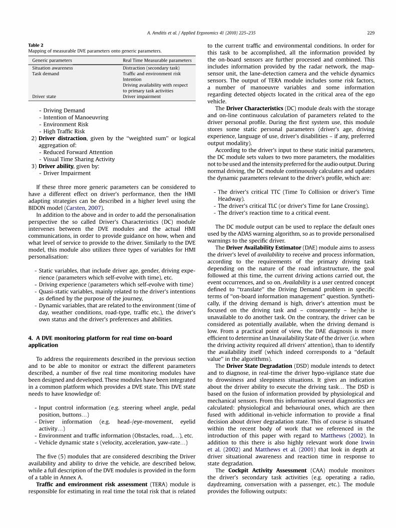
Table 2Mapping of measurable DVE parameters onto generic parameters.
Generic parameters Real Time Measurable parameters
Situation awareness Distraction (secondary task)Task demand Traffic and environment risk
IntentionDriving availability with respectto primary task activities
Driver state Driver impairment
A. Amditis et al. / Applied Ergonomics 41 (2010) 225–235 229
- Driving Demand- Intention of Manoeuvring- Environment Risk- High Traffic Risk
2) Driver distraction, given by the ‘‘weighted sum’’ or logicalaggregation of:- Reduced Forward Attention- Visual Time Sharing Activity
3) Driver ability, given by:- Driver Impairment
If these three more generic parameters can be considered tohave a different effect on driver’s performance, then the HMIadapting strategies can be described in a higher level using theBIDON model (Carsten, 2007).
In addition to the above and in order to add the personalisationperspective the so called Driver’s Characteristics (DC) moduleintervenes between the DVE modules and the actual HMIcommunications, in order to provide guidance on how, when andwhat level of service to provide to the driver. Similarly to the DVEmodel, this module also utilizes three types of variables for HMIpersonalisation:
- Static variables, that include driver age, gender, driving expe-rience (parameters which self-evolve with time), etc.
- Driving experience (parameters which self-evolve with time)- Quasi-static variables, mainly related to the driver’s intentions
as defined by the purpose of the journey,- Dynamic variables, that are related to the environment (time of
day, weather conditions, road-type, traffic etc.), the driver’sown status and the driver’s preferences and abilities.
4. A DVE monitoring platform for real time on-boardapplication
To address the requirements described in the previous sectionand to be able to monitor or extract the different parametersdescribed, a number of five real time monitoring modules havebeen designed and developed. These modules have been integratedin a common platform which provides a DVE state. This DVE stateneeds to have knowledge of:
- Input control information (e.g. steering wheel angle, pedalposition, buttons.)
- Driver information (e.g. head-/eye-movement, eyelidactivity.)
- Environment and traffic information (Obstacles, road,.), etc.- Vehicle dynamic state s (velocity, acceleration, yaw-rate.)
The five (5) modules that are considered describing the Driveravailability and ability to drive the vehicle, are described below,while a full description of the DVE modules is provided in the formof a table in Annex A.
Traffic and environment risk assessment (TERA) module isresponsible for estimating in real time the total risk that is related
to the current traffic and environmental conditions. In order forthis task to be accomplished, all the information provided bythe on-board sensors are further processed and combined. Thisincludes information provided by the radar network, the map-sensor unit, the lane-detection camera and the vehicle dynamicssensors. The output of TERA module includes some risk factors,a number of manoeuvre variables and some informationregarding detected objects located in the critical area of the egovehicle.
The Driver Characteristics (DC) module deals with the storageand on-line continuous calculation of parameters related to thedriver personal profile. During the first system use, this modulestores some static personal parameters (driver’s age, drivingexperience, language of use, driver’s disabilities – if any, preferredoutput modality).
According to the driver’s input to these static initial parameters,the DC module sets values to two more parameters, the modalitiesnot to be used and the intensity preferred for the audio output. Duringnormal driving, the DC module continuously calculates and updatesthe dynamic parameters relevant to the driver’s profile, which are:
- The driver’s critical TTC (Time To Collision or driver’s TimeHeadway).
- The driver’s critical TLC (or driver’s Time for Lane Crossing).- The driver’s reaction time to a critical event.
The DC module output can be used to replace the default onesused by the ADAS warning algorithm, so as to provide personalisedwarnings to the specific driver.
The Driver Availability Estimator (DAE) module aims to assessthe driver’s level of availability to receive and process information,according to the requirements of the primary driving taskdepending on the nature of the road infrastructure, the goalfollowed at this time, the current driving actions carried out, theevent occurrences, and so on. Availability is a user centred conceptdefined to ‘‘translate’’ the Driving Demand problem in specificterms of ‘‘on-board information management’’ question. Syntheti-cally, if the driving demand is high, driver’s attention must befocused on the driving task and – consequently – he/she isunavailable to do another task. On the contrary, the driver can beconsidered as potentially available, when the driving demand islow. From a practical point of view, the DAE diagnosis is moreefficient to determine an Unavailability State of the driver (i.e. whenthe driving activity required all drivers’ attention), than to identifythe availability itself (which indeed corresponds to a ‘‘defaultvalue’’ in the algorithms).
The Driver State Degradation (DSD) module intends to detectand to diagnose, in real-time the driver hypo-vigilance state dueto drowsiness and sleepiness situations. It gives an indicationabout the driver ability to execute the driving task. The DSD isbased on the fusion of information provided by physiological andmechanical sensors. From this information several diagnostics arecalculated: physiological and behavioural ones, which are thenfused with additional in-vehicle information to provide a finaldecision about driver degradation state. This of course is situatedwithin the recent body of work that we referenced in theintroduction of this paper with regard to Matthews (2002). Inaddition to this there is also highly relevant work done Irwinet al. (2002) and Matthews et al. (2001) that look in depth atdriver situational awareness and reaction time in response tostate degradation.
The Cockpit Activity Assessment (CAA) module monitorsthe driver’s secondary task activities (e.g. operating a radio,daydreaming, conversation with a passenger, etc.). The moduleprovides the following outputs:

A. Amditis et al. / Applied Ergonomics 41 (2010) 225–235230
- Eyes-off-road, whether the driver’s attention is focused to roadahead or not
- Visual time sharing, indication that the driver is continuouslytaking short glances off the road, hence sharing his/her atten-tion between two targets
- Cognitive distraction, the driver’s mental mind is not fullyconcentrated for driving due to daydreaming, thinking some-thing, fatigue, etc.
- Further, driver mirror checks, which may indicate intention tochange lane, are detected. On a basis of this a ‘‘lateralmanoeuvring intent’’ parameter (based solely on mirrorchecks) is output from the CAA and passed on to the TERAmodule, which uses this parameter in a more complete intentassessment algorithm.
Each DVE module is a prototype software component and isbased on sensors and processing units that monitor the driver, thevehicle and the environment. Specific sensor adaptation wascarried out, where needed.
Finally the DVE platform (Fig. 2) collects data from all on-boardsensors and other application modules. In practice, this is a piece ofsoftware that:
- Runs on a computer in the vehicle- Reads sensor data from the vehicle bus.- Communicates with the DVE module software by means of
direct DLL calls or custom-made IP communication protocols.- Delivers sensor data to the DVE modules in real-time.- Receives DVE parameter output data from the DVE modules in
real-time, and transmits this output data on the vehicle CANbus.
These data are synchronously amassed inside a container (poolof data). The following sensor data get captured: Vehicle Dynamics,Driver’s Actions, Lane Information, Detected Targets and driver’sprofile specifications (PM) all received through a CAN bus. More-over, eyelid movement data and cockpit activities (CAA) can bereceived either via a CAN or a TCP/IP channel. Map and gyroinformation are collected by ADASRP application, which runs onthe same computer as the one on which DVE platform is running,by a mechanism of shared memory (Inter Process Communication,IPC). Lastly, driver’s degradation state is obtained by establishinga bidirectional Ethernet communication between DVE platform andDSD application: the platform provides DSD with all necessaryinput, for that the later will output a diagnosis of the driver’s state(Amditis et al., 2007). Thus, one could say that the output of the
Fig. 2. Data acquisition scheme.
DVE platform is a synchronised information of the state of thedriver, the vehicle and the environment.
In addition, the DVE Platform provides logging possibilities, anda means of visualizing sensor data and DVE output data. Theavailable data visualization windows are schematically shown inthe following figure (Fig. 3).
- The left part, named Variables Panel, shows the input variablesflowing on the CAN line,
- The central part, named Radar Panel, shows the GUI of vehicleenvironment containing the scanned object, the road lanes andthe estimation of future trajectory,
- The right part, named Decision Monitor, shows the DVE outputvalues.
In particular, in the Decision Monitor the values [normal,intermediate, high] of seven DVE parameters (driver availability,traffic risk, environment risk, driver impairment, visual timesharing, cognitive distraction, visual distraction) are represented inhistograms with different colours, while for the manoeuvreintention only ‘‘yes/no’’ indication is reported. As shown in thefollowing figure, the normal value is represented with an empty barin the histogram, while the intermediate value is represented witha blue bar and the high value with a red bar (Fig. 4).
5. Validation and functionality tests of DVE modules
In this section we will take an in-depth look at the methodologyof the DVE validation procedure. The DVE modules have beenthrough a thorough testing in different environments. In order toassess the functionality of the overall AIDE systems, lab-tests andtests in real roads with drivers have been carried out. These labtests included functional and technical verification, communicationand integration tests. Multiple iterations have been performedbased on the intermediate test results and on real data gathered bythe prototype vehicles.
Then the modules have been integrated to the DVE platform andadditional tests have been performed with the platform to test andvalidate communication between the platform and the vehiclesystems, as well as between the DVE sub-systems themselves.Inputs and outputs of the platform have been tested and the dataflows were verified. A set of four questionnaires was designed to beused at the tests, that are briefly described below.
A. Personal data questionnaire (if users are involved)
This questionnaire was filled only when users were involved intests. The aim has been to record their personal details (age, gender,profession, driving experience, experience in using in-vehicledevice, etc.).
B. User acceptance questionnaire (if users are involved)
This questionnaire was filled only when users were involved intests. In this questionnaire, the user’s opinion is tracked regardingthe module usefulness, pleasantness, effectiveness, reliability,helpfulness, etc. The score is given in a 5-point scale.
C. Quality of service questionnaire
This questionnaire was filled for all the tested modules. It dealswith technical issues that affect the quality of the module’s func-tionality. More specifically, the questions given to the user areabout response time, loading time, system crash, error messages (ifany), usefulness of info/warning provided by the system and level

Fig. 3. AIDE DVE platform GUI layout.
A. Amditis et al. / Applied Ergonomics 41 (2010) 225–235 231
of personalisation (if applicable). Again, the score is given ina 5-point scale.
D. Monitoring template
This template aimed at gathering possible technical problemstracked during the tests and was filled by the developers of themodules. Each developer reported a short description of theproblem if that occurred.
For the verification of the AIDE system functionality, a CommonVerification Plan was determined which specified the way that thewhole system should be verified. As part of the overall system, theDVE modules were verified during this procedure as well. As anexample we provide hereafter a test scenario applied during theverification tests, on the DVE component with the ICA and thevehicle CAN functioning all together.
The purpose of this test scenario was to replace the synthesizedDVE vector with real values as computed by the DVE modules. Firstof all, it has been verified that the DVE estimation behaves asexpected and that the decision making of the HMI was reasonable.Parameter tuning such as adjusting the time-to-calm1 hysteresishas been performed as a result of this procedure. This test wasperformed by driving a certain route containing traffic situationsthat are representative to all the DVE functionality. For the Truckdemonstrator an evaluation test track has been used. The selectedroute contains sections of urban, rural and highway roads. Each testdrive has been recorded, with the help of the DVE platform visu-aliser, and data were sent to the DVE developers together withcomments on the behaviour of the modules, in order to optimisethe behaviour of the DVE modules. The procedure was repeateduntil the desired behaviour was achieved.
1 Time-to-Calm is a time delay from when the DVE state changes from a statethat don’t allow a certain HMI interaction to a state that allows it to when the ICAactually approves the interaction. The purpose of time-to-calm is to ensure thata warning or an information does not follow too close after a situation of high driverworkload.
Finally, tests with the vehicles and users were performed. Awithin subject design with three conditions was applied accordingto the recommendations in the AIDE Cookbook:
- with system integration and AIDE functionality (AIDEcondition)
- without integration and AIDE functionality (Non-AIDEcondition)
- baseline condition without any IVIS or ADAS (Control)
Thus, all drivers drove three times. The order of experimentalconditions was counterbalanced across participants. All threedrives took place at one and the same occasion. Each drive lastedfor approx 30–45 min. The drivers were provided with written andoral information prior to the actual drive. Driving was preceded bya training session, during which the drivers were familiarize withthe cars and learned the functions which were tested during theAIDE /Non-AIDE conditions. They were also told to train and learnthe system and user interface so much that they felt comfortablewith the test situation. Furthermore, all Use Cases (tasks) wererehearsed before the test drive. Even so, it was a novel situation forthem and no long-term effects can be derived from these testresults. There are several advantages with a within-subject design.There are no between group variations and familiarisation withvehicle and ADAS/IVIS is made once for all experimental conditions.The counterbalance of conditions was very critical.
The following common inclusion criteria were used whenrecruiting subjects:
- Gender: equal gender distribution if possible- Age: from 35 to 55 years old- Driving experience was considered in order to select proved
experience drivers to avoid possible malfunctions due to thelack of practice (more than 15,000 km driven annually andmore than 5 years with driving license).
- Subjects of the SEAT and VOLVO demonstrator’s experimentswere asked about English language (speak and understanding)since the interface and the speech commands (phone andaudio) were in English. For the CRF demonstrator it was not

Fig. 4. DVE decision monitor.
A. Amditis et al. / Applied Ergonomics 41 (2010) 225–235232
necessary since the experiment was performed in Italianlanguage.
- Participants were asked not to be dependent on eyeglasseswhile driving, since this might disturb the eye tracking system.
A wide range of both objective and subjective measures wereused in the three evaluations. In total fifty-seven drivers partici-pated in the evaluations. The majority were male drivers 87%and only 13% female drivers. The target age range was 35–55 butthere were some younger and some older drivers included due tointernal driving restrictions. All drivers fulfilled the experiencerequirements, i.e. holding a driving license for at least 5 years anddriver more than 15,000 km annually.
The DVE modules developed as a result of the above procedures,enabled five different types of HMI adaptivity features, which areoutlined below:
1. Action postponing2. Intensity increase3. Intensity increase and repetition4. Non-visual presentation5. Warning adaptation
As an example of how the DVE modules aid the HMI to adapt,the following table highlights the specific case of the DC module.DC module attempts to satisfy the user needs for warning infopersonalisation of all drivers, but with emphasis on the drivercohorts. Here we see how the presentation of the message isadjusted to the driver’s characteristics and therefore the DC modulemay indicate the best modality of presentation for each action(Table 3):
6. Discussion
The parameters and variables of Driver–Vehicle–Environmentmodel have been identified, by defining, reviewing and selectingthe most relevant indicators of any kind of potential behaviouraladaptation within the driving activity. The existing relationships
Table 3How the HMI adopts to the outputs of the DC module.
DC parameter Explanation
Driver’s reaction time This parameter indicates if the driver hand if as a consequence the warnings aanticipated or given with an enhanced
between variables and parameters were explained by means ofmetrics selection.
This analysis of parameters and indicators allows to understandand representing the interaction between the three components ofthe road system, namely: the Driver, the Vehicle and the Environ-ment. This basic understanding of the DVE triptych is necessary toidentify the basic requirements of the development and in-vehicleimplementation of the DVE real time monitoring and person-alisation modules.
The foundations for the description of the parameters understudy and for the selection of the most appropriate variables to usewithin the DVE model have been explained. The model that hasfinally been devised to describe the effects on the DVE behaviourand that enables to perform a simple prediction DVE conditions hasbeen called ‘‘Basic Indicators of Driver Operational Navigation’’(BIDON). By means of the BIDON model, the effects of variousvariables derived from the dynamic evolution of the environmentand vehicle are accounted for. The BIDON Model represents thelogical link between the research and development actions.
The objectives of the theoretical work on guidelines forsupporting designers in applying models of DVE in a design process,involving ADAS and IVIS, have been reached by:
- Defining a modelling architecture;- Selecting of a number of parameters and measurable variables
that affect driver performance and behaviour;- Defining a set of scenarios that should be analysed with the
DVE model in order to evaluate effectiveness and efficiency ofthe system at design level;
- Devising a stepwise procedure on how to apply these conceptsin a user centred design approach.
The actual modelling structure and the Task Analysis, that arethe combined instruments by which the driver model transformsits theoretical configuration in a sequence of activities and behav-iours, have been established. The model, that was defined, isimplemented in a simulation and into a set of real time modules,demonstrated the ability to assess the state of the Driver, theVehicle and the Environment.
Value
as as a slow or fast reaction timend prioritised actions have to bemodality
2 levels¼ (slow driver,fast driver)
A. Amditis et al. / Applied Ergonomics 41 (2010) 225–235 233
The DVE modules were subjected to extensive evaluation,following the procedure described above. From this it emerged thata key innovation of the AIDE system is its rich DVE state vector,featuring a large number of DVE state parameters, and it is inter-esting to note how this allows for a flexible and transparent processof defining adaptive HMI function. From an HMI developer point ofview it is more straightforward to work with statements such as ‘‘ina situation with high traffic risk (measured within a DVE module)only messages of priority level P or higher should be let through’’,rather than ‘‘in a situation with Driving Complexity being of level X(generic parameters) only messages of priority level P or highershould be let through’’. From this we infer that it is valuable tomatch the generic parameters with the measurable parametersthat can be arrived at through the DVE modules.
From the research work performed it was clear that additionalresearch is needed in a number of sectors in the DVE modulesdevelopment. An important topic for future research, should be theidentification of the more efficient and useful outcomes of theDVE monitoring modules. These outcomes can be both a fused valueof the findings of the above-mentioned modules but also a number oflow-level signals or individual outcomes useful to the other modulesof the system. Thus, the main output from the aforementioneddescribed modules will be variables representing the respectivedimensions (i.e. the driver characteristics, the level of impairment,the level of secondary task involvement/distraction and the traffic/environment scenario). Together, these will form a rich vector rep-resenting the current driver–vehicle–environment state.
One of the most important constraints of the design anddevelopment of the DVE modules tasks was to try to reuse as muchas possible existing algorithms and systems that were developed inprevious research initiatives or that were available ‘‘on the shelf’’. Itshould be noticed that substantial improvements and innovationhave been brought to most of the DVE modules. Therefore it is clearthat these innovations need to be related with the optimised andcost effective use of sensors, systems and components for theimplementation of the DVE modules.
Finally, a wider testing and validation methodology which isable to identify the critical values and thresholds of the DVEparameters is also an area where further research is needed.
7. Conclusions
The overall objective of the work performed has been thedesign, development and validation of an innovative adaptiveintegrated driver–vehicle interface which aims to maximise theefficiency and the safety benefits of advanced driver assistancesystems, to minimise the level of workload and distraction imposedby in-vehicle information systems and nomad devices. To reachthese objectives, real-time monitoring of the driver as well as thevehicle surrounding environment is needed in order to achievea multi-dimension Driver–Vehicle–Environment (DVE) state. Thisincludes obtaining real-time information on the traffic environ-ment, the driver state, activity and characteristics:
Table 4Table of DVE parameters.
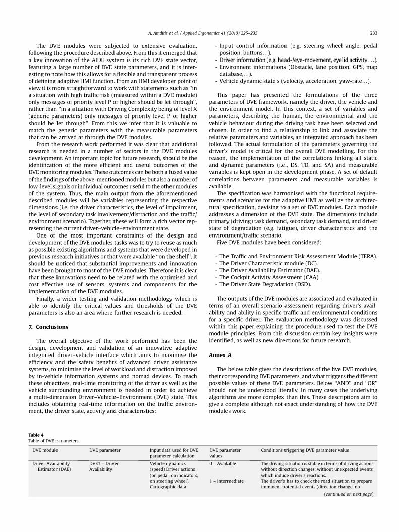
DVE module DVE parameter Input data used for DVEparameter calculation
Driver AvailabilityEstimator (DAE)
DVE1 – DriverAvailability
Vehicle dynamics(speed) Driver actions(on pedal, on indicators,on steering wheel),Cartographic data
- Input control information (e.g. steering wheel angle, pedalposition, buttons.).
- Driver information (e.g. head-/eye-movement, eyelid activity . . .).- Environnent informations (Obstacle, lane position, GPS, map
database,.).- Vehicle dynamic state s (velocity, acceleration, yaw-rate.).
This paper has presented the formulations of the threeparameters of DVE framework, namely the driver, the vehicle andthe environment model. In this context, a set of variables andparameters, describing the human, the environmental and thevehicle behaviour during the driving task have been selected andchosen. In order to find a relationship to link and associate therelative parameters and variables, an integrated approach has beenfollowed. The actual formulation of the parameters governing thedriver’s model is critical for the overall DVE modelling. For thisreason, the implementation of the correlations linking all staticand dynamic parameters (i.e., DS, TD, and SA) and measurablevariables is kept open in the development phase. A set of defaultcorrelations between parameters and measurable variables isavailable.
The specification was harmonised with the functional require-ments and scenarios for the adaptive HMI as well as the architec-tural specification, devising to a set of DVE modules. Each moduleaddresses a dimension of the DVE state. The dimensions includeprimary (driving) task demand, secondary task demand, and driverstate of degradation (e.g. fatigue), driver characteristics and theenvironment/traffic scenario.
Five DVE modules have been considered:
- The Traffic and Environment Risk Assessment Module (TERA).- The Driver Characteristic module (DC).- The Driver Availability Estimator (DAE).- The Cockpit Activity Assessment (CAA).- The Driver State Degradation (DSD).
The outputs of the DVE modules are associated and evaluated interms of an overall scenario assessment regarding driver’s avail-ability and ability in specific traffic and environmental conditionsfor a specific driver. The evaluation methodology was discussedwithin this paper explaining the procedure used to test the DVEmodule principles. From this discussion certain key insights wereidentified, as well as new directions for future research.
Annex A
The below table gives the descriptions of the five DVE modules,their corresponding DVE parameters, and what triggers the differentpossible values of these DVE parameters. Below ‘‘AND’’ and ‘‘OR’’should not be understood literally. In many cases the underlyingalgorithms are more complex than this. These descriptions aim togive a complete although not exact understanding of how the DVEmodules work.
DVE parametervalues
Conditions triggering DVE parameter value
0 – Available The driving situation is stable in terms of driving actionswithout direction changes, without unexpected eventswhich induce driver’s reactions.
1 – Intermediate The driver’s has to check the road situation to prepareimminent potential events (direction change, no
(continued on next page)

Table 4 (continued )
DVE module DVE parameter Input data used for DVEparameter calculation
DVE parametervalues
Conditions triggering DVE parameter value
(information on currentand next segments)
priority intersection crossing, and approach from anentry or on exit on the highway, approach to big curveswhich need demanding trajectory control).
2 – Not available The driver is not available to receive no urgentinformation. He is in a very demanding situation interms of driving demand. It should be occurs duringintersection crossing, roundabout crossing, overtakingmanoeuvre, entry or exit from highway, big curveswhich induce demanding trajectory control,unexpected event (pedestrian, vehicle) which induceurgent driver’s response (braking, steering wheelmovement). The diagnostics are different according tothe context (highway, urban, rural). The approach zonesare shorter in urban than in rural and highway contexts.
Cockpit ActivityAssessment (CAA)
DVE2.1 –Eyes-Off-Road
Driver head-/eye-movements (vehiclespeed)
0 – No Driver is currently looking at the road ahead1 – Yes Driver is currently looking at something else than the
road ahead2 – Unknown Head/eye sensor not tracking
ORHead/eye tracking calibration not completed (w30 s ofdriving at> 30 km/h)
DVE2.2 – VisualTime Sharing
Driver head-/eye-movements, buttonpresses(, vehicle speed)
0 – No Driver head-/eye-movements do not indicate visualtime sharing activity (regardless of button presses)
1 – Yes Driver is sharing his visual attention between the roadahead and something elseORDriver is using buttons
2 – Unknown Head/eye sensor not trackingORHead/eye tracking calibration not completed
DVE2.3 – CognitiveDistraction
Driver head-/eye-movements, laneposition(, vehiclespeed)
0 – No Driver behaviour does not indicate cognitive distraction1 – Yes Driver gaze concentration towards road ahead
AND/ORImproved lane keeping performance
2 – Unknown Average speed last 15 s is below 60 km/hDriver State
Degradation(DSD)
DVE3 – Driverimpairment
Driver eyelid closure,lane positioning,Driving time
A first step is to calculate the physiological measure of the driver’s level ofalertness:
- Alert – Extremely alert to rather alert, no large blink and less then 1 verylarge blink on the time window analysis.
- Slightly drowsy – Neither alert nor sleepy, some signs of sleepiness. Somelarge blinks and less then one very large blink on the time window analysis.
- Drowsy – Sleepy, but no effort to keep alert: some large blinks or some verylarge blinks on the time window analysis
- Sleepy – very sleepy, great effort to keep alert, fighting sleep, blinks withduration greater then 750 ms
0 – normal Alert and not or few driving errors1 – slightly critical Slightly drowsy with no or few driving errors
ORAlert but major driving errors and long trip durationand critical driving time (according to circadian cycle)ORDrowsy with no driving errors short trip duration, andnot critical driving time
2 –Critical Drowsy with no or few driving errorsORSleepy with no driving errors short trip duration, andnot critical driving timeORslightly drowsy but major driving errors and long tripduration and critical driving time (according tocircadian cycle)
3 – Dangerous SleepyOrDrowsy with major or some driving errors and criticaldriving time and middle or long trip duration
Traffic andEnvironmentRisk Assessment(TERA)
DVE4 – DriverManoeuvringIntention
Indicator, manoeuvretype, left and right lanemarking type,curvature, repeatedmirror checks (only inVolvo), velocity, time tolane crossing, distanceto lane crossing, lateral
0 – No The driver is moving on straight or curved path withoutperforming lateral displacement.
1 – Yes The driver is intending to change lane in the future andthe module predicts the maneuver before indicator isactivated
2 – No The module can not predict the manoeuvring intentionbased on the current information.
A. Amditis et al. / Applied Ergonomics 41 (2010) 225–235234
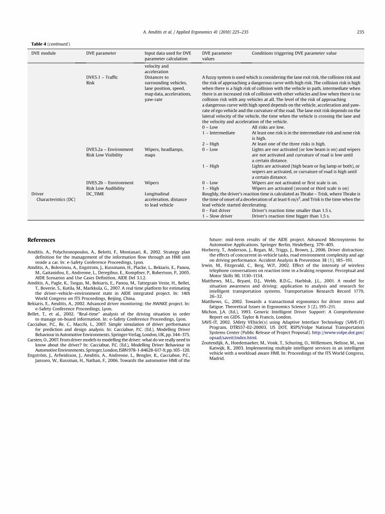
Table 4 (continued )
DVE module DVE parameter Input data used for DVEparameter calculation
DVE parametervalues
Conditions triggering DVE parameter value
velocity andacceleration
DVE5.1 – TrafficRisk
Distances tosurrounding vehicles,lane position, speed,map data, accelerations,yaw-rate
A fuzzy system is used which is considering the lane exit risk, the collision risk andthe risk of approaching a dangerous curve with high risk. The collision risk is highwhen there is a high risk of collision with the vehicle in path, intermediate whenthere is an increased risk of collision with other vehicles and low when there is nocollision risk with any vehicles at all. The level of the risk of approachinga dangerous curve with high speed depends on the vehicle, acceleration and yaw-rate of ego vehicle and the curvature of the road. The lane exit risk depends on thelateral velocity of the vehicle, the time when the vehicle is crossing the lane andthe velocity and acceleration of the vehicle.0 – Low All risks are low.1 – Intermediate At least one risk is in the intermediate risk and none risk
is high.2 – High At least one of the three risks is high.
DVE5.2a – EnvironmentRisk Low Visibility
Wipers, headlamps,maps
0 – Low Lights are nor activated (or low beam is on) and wipersare not activated and curvature of road is low untila certain distance.
1 – High Lights are activated (high beam or fog lamp or both), orwipers are activated, or curvature of road is high untila certain distance.
DVE5.2b – EnvironmentRisk Low Audibility
Wipers 0 – Low Wipers are not activated or first scale is on.1 – High Wipers are activated (second or third scale is on)
DriverCharacteristics (DC)
DC_TIME Longitudinalacceleration, distanceto lead vehicle
Roughly, the driver’s reaction time is calculated as Tbrake – Trisk, where Tbrake isthe time of onset of a deceleration of at least 6 m/s2, and Trisk is the time when thelead vehicle started decelerating.0 – Fast driver Driver’s reaction time smaller than 1.5 s.1 – Slow driver Driver’s reaction time bigger than 1.5 s.
A. Amditis et al. / Applied Ergonomics 41 (2010) 225–235 235
References
Amditis, A., Polychronopoulos, A., Belotti, F., Montanari, R., 2002. Strategy plandefinition for the management of the information flow through an HMI unitinside a car. In: e-Safety Conference Proceedings, Lyon.
Amditis, A., Bolovinou, A., Engstrom, J., Kussmann, H., Placke, L., Bekiaris, E., Panou,M., Gaitanidou, E., Andreone, L., Deregibus, E., Kompfner, P., Robertson, P., 2005.AIDE Scenarios and Use Cases Definition, AIDE Del 3.1.2.
Amditis, A., Pagle, K., Tsogas, M., Bekiaris, E., Panou, M., Tattegrain Veste, H., Bellet,T., Boverie, S., Kutila, M., Markkula, G., 2007. A real time platform for estimatingthe driver–vehicle–environment state in AIDE integrated project. In: 14thWorld Congress on ITS Proceedings, Beijing, China.
Bekiaris, E., Amditis, A., 2002. Advanced driver monitoring: the AWAKE project. In:e-Safety Conference Proceedings, Lyon.
Bellet, T., et al., 2002. ‘‘Real-time’’ analysis of the driving situation in orderto manage on-board information. In: e-Safety Conference Proceedings, Lyon.
Cacciabue, P.C., Re, C., Macchi, L., 2007. Simple simulation of driver performancefor prediction and design analysis. In: Cacciabue, P.C. (Ed.), Modelling DriverBehaviour in Automotive Environments. Springer-Verlag, London, UK, pp. 344–375.
Carsten, O., 2007. From driver models to modelling the driver: what do we really need toknow about the driver? In: Cacciabue, P.C. (Ed.), Modelling Driver Behaviour inAutomotive Environments. Springer, London, ISBN 978-1-84628-617-9, pp.105–120.
Engstrom, J., Arfwidsson, J., Amditis, A., Andreone, L., Bengler, K., Cacciabue, P.C.,Janssen, W., Kussman, H., Nathan, F., 2006. Towards the automotive HMI of the
future: mid-term results of the AIDE project. Advanced Microsystems forAutomotive Applications. Springer Berlin, Heidelberg. 379–405.
Horberry, T., Anderson, J., Regan, M., Triggs, J., Brown, J., 2006. Driver distraction:the effects of concurrent in-vehicle tasks, road environment complexity and ageon driving performance. Accident Analysis & Prevention 38 (1), 185–191.
Irwin, M., Fitzgerald, C., Berg, W.P., 2002. Effect of the intensity of wirelesstelephone conversations on reaction time in a braking response. Perceptual andMotor Skills 90, 1130–1134.
Matthews, M.L., Bryant, D.J., Webb, R.D.G., Harbluk, J.L., 2001. A model forsituation awareness and driving: application to analysis and research forintelligent transportation systems. Transportation Research Record 1779,26–32.
Matthews, G., 2002. Towards a transactional ergonomics for driver stress andfatigue. Theoretical Issues in Ergonomics Science 3 (2), 195–211.
Michon, J.A. (Ed.), 1993. Generic Intelligent Driver Support: A ComprehensiveReport on GIDS. Taylor & Francis, London.
SAVE-IT, 2002. SAfety VEhicle(s) using Adaptive Interface Technology (SAVE-IT)Program, DTRS57-02-20003. US DOT, RSPS/Volpe National TransportationSystems Center (Public Release of Project Proposal). http://www.volpe.dot.gov/opsad/saveit/index.html.
Zoutendijk, A., Hoedemaeker, M., Vonk, T., Schuring, O., Willemsen, Nelisse, M., vanKatwijk, R., 2003. Implementing multiple intelligent services in an intelligentvehicle with a workload aware HMI. In: Proceedings of the ITS World Congress,Madrid.