Embed Size (px)
Citation preview

Features and Solutions ............................................................... 3Selecting a Power Moller ........................................................ 4-6
DC Model RollersPM320HS ................................................................................... 7PM486FE ................................................................................ 8-9PM486FS ............................................................................ 10-11PM486FP ............................................................................ 12-13PM486FH ................................................................................. 14PM486LD ................................................................................. 15PM486XE/XP ...................................................................... 16-17PM570FE ............................................................................ 18-19PM570KE/KT ...................................................................... 20-21PM605FE ............................................................................ 22-23PM635FS ............................................................................ 24-25PM635KE/KT ....................................................................... 26-27
Driver CardsCB-016S7 .................................................................................. 28CB-030S .................................................................................... 29CBM-103 .................................................................................. 30CBM-105 .................................................................................. 31CBM-107 .................................................................................. 32Snap-In-Drive ............................................................................ 33
Hybrid CardHB-510 .................................................................................... 34HBM-604 .................................................................................. 35HBL-606 .................................................................................... 36HBK-608 ................................................................................... 37
2-Zone ControllerIB-E03 ...................................................................................... 38IB-E04 ....................................................................................... 39
AC Model RollersPM380AS ................................................................................. 40PM427AS ................................................................................. 41PM486BS ................................................................................. 42PM570AS ................................................................................. 43PM570BP ................................................................................. 44PM570AU ................................................................................ 45PM605AS ................................................................................. 46PM605BP ................................................................................. 47PM605AU ................................................................................ 48PM763BS .................................................................................. 49
TransfersF-RAT-S ............................................................................... 50-51
DiagramsTerminal Blocks ........................................................................ 52Mounting Brackets .............................................................. 53-54Extension Cables ..................................................................... 55Technical Information ......................................................... 56-58Options ............................................................................... 59-60Belt Pulleys / Grooves ............................................................. 61Installation Precautions ............................................................ 62AC Wiring ............................................................................ 63-64
Specifications in this catalog are subject to change without prior notice.

In today’s progressive manufacturing and distribution environments, designing conveyor systems can be a difficult challenge. Complex problems often need to be solved. Now there is an innovative and advanced engineering solution that meets the demands of a new age in production automation and flexibility. The Power Moller™ is a self-contained motorized roller that opens new horizons in handling system design. Its low profile and ease of installation make it the perfect choice when production efficiency and space savings are required.
Working ConceptThe turning force of the motor is transmitted through the shock absorber to the planetary gearing. The planetary gearing drives the inner gear which is affixed to the roller tube. The tube will rotate because the output shaft is held stationary by the conveyor frame.
“One Touch” Spring Loaded ShaftThe Power Moller spring-loaded attaching shaft enables the unit to be quickly installed or removed without disassembling the conveyor frame
Space SavingMotor and Gearbox integral with roller tube
Easy InstallationSpring-loaded shaft enables quick and easy installation into new or existing equipment
Safe, Simple and CleanTotally sealed construction with no exposed chains or sprockets
Quiet and Smooth OperationEnables low vibration transfer
Maintenance FreeLifetime lubrication ensures long life and maintenance free operation
Built-in Shock AbsorberProtects the gearbox from a sudden stop, impact, or acceleration in the line
Easy WiringSupplied mounting fitting with terminal block and safety cover secures the motor shaft to the frame and provides for easy and convenient wiring
ReversibleEasy control of forward, reverse and stop functions
SPRING LOADED SHAFT
ABEC 1 BEARINGS HIGH PERFORMANCE MOTOR
PLANETARY GEAR TRAIN
SHOCK ABSORBER
STEEL ZINC PLATED TUBE
Features and Solutions
3
What is Conveying Confidence?
Conveying Confidence is the reassurance our customers realize from knowing they are partnering with the only sole source motor and control manufacturer in the industry. This peace of mind is reinforced by the fact that we test each and every roller that goes out the door - no exceptions.
With over 10 million rollers sold throughout 40 countries and 5000 businesses worldwide, I am confident your experience with Itoh Denki, its products and service, will be everything you expected, and more.
Kazuo ItoPresident, Itoh Denki Inc.

54 WWW.ITOHDENKI.COM n 888.310.8811
HOW TO SPECIFY THE LENGTH OF A POWER MOLLER™ (Between Frame dimension - BF)In determining the correct length of the Power Moller required, you should first obtain the Between Frame (BF) width of the conveyor you will be mounting the Power Moller in. If this dimension is in inches, you should convert the dimension to millimeters, as all Power Moller Tube Lengths (TL) are in metric units. From this dimension, sub-tract 15mm for bearing End Caps (EC) and clearances to achieve the correct tube length. Subtract 20mm when using PM635FS. Subtract 30mm when using PM763BS.
Example: BF measures 15 inches. Converting to millimeters 15” X 25.4mm / in. = 381mm. Deducting 15mm for bearing EC and clearances, 381mm - 15mm = 366mm. TL will be 366mm long. When in doubt, contact an Itoh Denki representative to help you in selecting the correct Power Moller for your application.
* Please refer to specific product page and diagram for proper EC deduction when determining roller length.
TL=BF-EC
n Options Does the application call for any special options? Lagging (Natural rubber, NBR, Neoprene, Urethane) Dustproof Waterproof Brake Clutch Other KF - Brackets not ordered with roller
Important FormulasTangential Force (TF)n Tangential force is the force in lbs. that is needed to move the item on the conveyor. The force tangent to the roller’s surface. Tangential force F can be found by the following formula:
Formula 1TF = µ X WTF = Required tangential forceW = Weight of article to be transferredµ = Coefficient of rolling friction in accordance with the material composition of the bottom of the article to be transferred. (See Table 1 on following page)
To determine the number of Power Moller units required for transfer, compare required tangential force (F) and the tangential force of one Power Moller unit (f)
Formula 2Number of Power Mollers required = F/f
5mm [0.20"] 5mm [0.20"]
2.5mm [0.10"] 2.5mm [0.10"]
366mm [14.41"]
381mm [15.00"]
Bearing End Cap Bearing End Cap
Clearance Clearance
Tube Length (TL)
Between Frame (BF)
STANDARD PART NUMBER EXAMPLE
PM486FE-60-747-D-024
Voltage: 24V
Voltage Type: DC
Tube Length: 747mm
Speed Code: Nominal 60m/min
Brushless DC Motor: Output on cable side shaft
Diameter: 48.6mm
Model Type: Power Moller
HOW TO SELECT A POWER MOLLER™
n Material What is in contact with the Motorized Roller? Metal Plastic Wood Urethane Natural rubber Corrugated cardboard Other material
n Product weight What will be the maximum weight?
n Available voltage What voltage are you using? 24V DC 3 phase 230V AC @ 60Hz Single phase 115V AC @ 60Hz Other Voltages
n Desired transportation speed How fast do you want to move the article? Feet/minute (FPM)
n Diameter of the roller What diameter are you looking for?
Common Itoh Denki Roller Diameters 1.50” (38.0mm) 1.68” (42.7mm) 1.91” (48.6mm) 2.25” (57.0mm) 2.38” (60.5mm) 2.50” (63.5mm) 3.00” (76.3mm)
Selecting a Power Moller

6 7WWW.ITOHDENKI.COM n 888.310.8811
Table I - Coefficient of Rolling Friction (µ) Product MaterialTube Material Metal Plastic Wood Urethane Natural
RubberCorrugated Cardboard
Steel 0.01 - 0.03 0.02 - 0.04 0.02 - 0.05 0.02 - 0.05 0.03 - 0.05 0.07 - 0.11
Urethane Lagging 0.02 - 0.05 0.02 - 0.05 0.02 - 0.05 0.02 - 0.05 0.03 - 0.05 0.07 - 0.11
Natural Rubber Lagging 0.03 - 0.05 0.03 - 0.05 0.03 - 0.05 0.03 - 0.05 0.03 - 0.05 0.07 - 0.11
The above values are based on industry standards of products with a smooth, uniform bottom surface in contact with the roller.
Example Material Cardboard Weight 25lbs. Voltage 3φ 230V AC @ 60Hz Speed 85FPM Diameter 2.25” BF 24” Options Nonen Tangential force required (Formula 1) Given W = 25lbs. Cardboard coefficient μ = 0.11 TF = μ X W TF = 0.11 X 25lbs. TF = 2.75lbs. required to move the article PM570AS-20 TF - 5.4lbs. > 2.75lbs. (See Performance Data, page 43)n Match/Best fit the diameter Diameter given 2.25” (57.0mm) Model - PM570n Given AC motor type Model number/motor type reflects AC or DC PM570ASn Select the best speed Speed code is an approximate meter-per-minute figure Varies by model Reference FPM values See speed table for PM570AS, page 43 Given 85FPM, Speed code 20 offers 89.6FPM Model number with speed code - PM570AS-20n Maximum Load Limit See maximum static load limit table, page 58 PM570 series 500 – 600mm tube length Maximum load limit of 176 lbs. per roller 25lbs. load < 176lbs. limit – Okayn Select the correct voltage PM570AS is an AC motor type Selected voltage is 3φ 230VAC @ 60Hz Model number with voltage - PM570AS-20-595-3-230n Options No options given
Final model number PM570AS-20-595-3-230 Description 2.25” Diameter Standard AC motor type 90.1 FPM 595mm Tube Length 3φ 230 VAC @ 60 Hz No Options
PM320HS DC Motor Driven Roller
CB-018N2 8 speed settings
DIP Switch Setting No-load Tangential Torque Speed SW1-4 SW1-5 SW1-6 speed force (lb) (lb·in)
Current (A)
Code CN2-5 CN2-4 CN2-3 (FPM) Starting Starting Starting No-Load Rated
30
off off off 19.0 18.5 11.7 2.00 0.10 0.60 off off on 32.5 18.5 11.7 2.00 0.18 0.64 off on off 42.7 18.5 11.7 2.00 0.23 0.66 off on on 52.2 18.5 11.7 2.00 0.28 0.69 on off off 61.7 18.5 11.7 2.00 0.34 0.72 on off on 72.2 18.5 11.7 2.00 0.39 0.75 on on off 81.0 18.5 11.7 2.00 0.44 0.77 on on on 94.5 18.5 11.7 2.00 0.50 0.80
____________________________________________________ ____________________________________________________ ____________________________________________________ ____________________________________________________ ____________________________________________________ ____________________________________________________ ____________________________________________________
Diameter: 1.26” (32.0mm)Voltage: 24V DC
Standard Featuresn Low-profile, compact design n Stable speed against varying loads n No hall effect sensors n Reversiblen Stainless steel exterior for wash down applications (IP 65)n Ideal for small belt applicationsn Brushless DC motor provides long lifen Crowned, seamless tuben 7/16” Hex shaft standardn ABEC 1 Bearings
Operationn Cycle: 1s ON; 1s OFF n Continuous or intermittent duty n Do not exceed 150% of no-load speed
Protectionn Motor is protected from overheating
Environmentn Ambient Temperature 32~104º F (0~40ºC)n No corrosive gasesn Vibration < 0.5G
Available Options
Minimum/Maximum Tube Lengths
170mm (6.69”)
570mm (22.44”)
This is a non-spring loaded shaft roller
]m
PM320H
S
Opposite Cable Side BracketAM-32HS-M5
1 Standard and 1 Opposite Cable mounting bracket needed for this rollerSee pages 53-54 for bracket diagrams
Standard Hex Shaft Mounting Brackets MBB-071 (Hex flat up)MBB-081 (Hex point up)
n Vibration < 0.5G Vibration < 0.5G
This is a non-spring loaded shaft roller
Standard Hex Shaft Mounting Brackets MBB-071 (Hex flat up)
12mm[0.47"]
150mm[5.91"]
6mm[0.24"]
6mm[0.24"]
Ø32m
m[1.
26"]
Tube Length in mm (TL)
Between Frame in mm (BF)
Crowned Crowned [0.47
"]12
mm
[0.44"11.1m8mm
[0.31"] 12mm
[0.47
"]
9mm
[0.36
"]
M5
TL=BF-12mmPM320HS Extension Cables AACB18-1000 (1000mm)AACB18-2000 (2000mm)

8 9WWW.ITOHDENKI.COM n 888.310.8811
PM486FE DC Motor Driven RollerDiameter: 1.91” (48.6mm)Voltage: 24V DC
Standard Featuresn Brushless DC motor provides long lifen 7/16” Hex (plain) shaft standardn ABEC 1 Bearingsn DOM, zinc plated, carbon steel tuben One shaft mounting, cable endn Dynamic braken Transport product up to 200lbs
Operationn Cycle: 1s ON; 1s OFF n Continuous or intermittent duty n Do not exceed 150% of no-load speed
Protectionn Thermal overload 221ºF (105ºC) in the motor when used with an Itoh Denki controller
Environmentn Ambient temperature 32~104º F (0~40ºC)n < 90% relative humidity (no condensation)n No corrosive gasesn Vibration < 0.5G
Available Options
Spring loaded shaft roller
n VP: BF - 35mm = TLn VG: BF - 41mm = TLn P2 double groove tube standard (50mm/32mm)n All shaft configurations available with grooved tube or straight tube
Minimum Tube Lengths
GEAR STAGES
1 2 3
244mm 267mm 290mm
(9.61”) (10.51”) (11.42”)
293mm 316mm 339mm
(11.54”) (12.44”) (13.35”)
302mm 325mm 348mm
(11.89”) (12.80”) (13.70”)
357mm 381mm 404mm
(14.06”) (15.00”) (15.91”)
CB-016S7 20 speed settings
3
2
1
5 24.0 6.9 95.0 90.8 3.6 0.3 1.6
8 34.1 6.9 98.5 94.2 4.0 0.4 2.1
10 44.7 6.9 95.0 90.8 4.0 0.5 2.4
17 55.3 6.9 77.4 74.0 4.0 0.8 2.8
20 85.3 24.6 30.3 29.0 3.6 0.3 1.6
30 121.4 24.6 31.5 30.1 4.0 0.4 2.1
45 159.1 24.6 30.3 29.0 4.0 0.5 2.4
60 196.8 24.6 24.7 23.7 4.0 0.8 2.8
70 303.2 87.6 9.7 9.3 3.6 0.3 1.6
100 431.5 87.6 10.1 9.6 4.0 0.4 2.1
140 565.6 87.6 9.7 9.3 4.0 0.5 2.4
210 699.7 87.6 7.9 7.6 4.0 0.8 2.8
No-load (FPM) SW1-5 on SW1-5 off Tangential Torque Current (A)Gear Speed SW5 9 SW5 0 force (lb) (lb·in) At highest speedStage Code High Low Starting Starting Starting No-Load Rated
HB-510N 10 speed settings
3
2
1
5 24.0 13.8 95.0 90.8 3.6 0.3 1.4
8 34.1 13.8 98.5 94.2 4.0 0.4 1.8
10 44.7 13.8 95.0 90.8 4.0 0.5 2.2
17 55.3 13.8 77.4 74.0 4.0 0.8 2.6
20 85.3 49.2 30.3 29.0 3.6 0.3 1.4
30 121.4 49.2 31.5 30.1 4.0 0.4 1.8
45 159.1 49.2 30.3 29.0 4.0 0.5 2.2
60 196.8 49.2 24.7 23.7 4.0 0.8 2.6
70 303.2 174.8 9.7 9.3 3.6 0.3 1.4
100 431.5 174.8 10.1 9.6 4.0 0.4 1.8
140 565.6 174.8 9.7 9.3 4.0 0.5 2.2
210 699.7 174.8 7.9 7.6 4.0 0.8 2.6
No-load (FPM) Tangential Torque Current (A)Gear Speed SW3 9 SW3 0 force (lb) (lb·in) At highest speedStage Code High Low Starting Starting Starting No-Load Rated
PM486FE
See page 34 for HB-510N diagram
Standard Hex Shaft Mounting Brackets MBB-071 (Hex flat up)MBB-081 (Hex point up)
Low Profile Hex Shaft Mounting BracketsMBC-071 (Hex flat up)MBC-081 (Hex point up)
1 mounting bracket needed for this rollerSee page 53 for bracket diagrams
JQ Shaft Standard Mounting Hardware Toothed lock washer and nutNuts to be tightened to 22.1lb • ft ± 10%
See page 28 for CB-016S7 diagram
Tube Length in mm (TL)
Between Frame in mm (BF)
15mm [0.59"]
32mm[1.26"]
50mm[1.97"]
17mm[0.67"]
300mm[11.81"]
5mm[0.20"]
5mm[0.20"]
11.1mm[0.44"]12
mm[0.
47"] Ø4
8.6mm
[1.91
"]
Standard Hex Shafts with Grooved TubeTL=BF-15mm
JQ - (Threaded Hex Shaft with Wrench Shoulder) / Straight Tube
Between Frame in mm (BF)BF=TL+21mm
Tube Length in mm (TL)
12mm
[0.47
"]
11.1mm[0.44"]
5mm[0.20"]
Ø48.6
mm[1.
91"]
12mm[0.47"]
300mm[11.81"]
13mm[0.51"] 15
mm[0.
59"]
10 MM(.39")
18.5 MM(.73")
21 MM(.83")
Wrench Shoulder Dimensions
Between Frame in mm (BF)
Tube Length in mm (TL)
12mm
[0.47
"]
11.1mm[0.44"]
15mm[0.59"]
5mm[0.20"]
Ø48.6
mm[1.
91"]
12mm[0.47"]
300mm[11.81"]
17mm[0.67"]
13mm[0.51"] 15
mm[0.
59"]
10 MM[.39"]
21 MM[.83"]
18.5 MM[.73"]
Detail A-AWrench Shoulder Dimensions
M12 X 1.25Toothed Lock Washer
13 M
M
A
A
TL=BF-21mm
TL Considerations for non-standard EC
See page 38 for IB-E03 diagram*Controls 2 Power Mollers

10 11WWW.ITOHDENKI.COM n 888.310.8811
PM486FS DC Motor Driven Roller
Standard Featuresn Brushless DC motor provides long lifen 7/16” Hex (plain) shafts standardn ABEC 1 Bearingsn DOM, zinc plated, carbon steel tuben Dual shaft mountingn Dynamic braken Time tested performancen Torque transmitted through ouput tube
Available Options
n P2 double groove tube standard (50mm/32mm)n All shaft configurations available with grooved tube or straight tube
Available as spring loaded or non spring loaded shaft
Minimum Tube Lengths
GEAR STAGES
2 3
254mm 277mm
(10.00”) (10.91”)
305mm 328mm
(12.01”) (12.91”)
305mm 328mm
(12.01”) (12.91”)
369mm 392mm
(14.53”) (15.43”)
315mm 338mm
(12.40”) (13.31”)
n JT shafts add 10mm to minimum tube length
CB-016S7 20 speed settings
3
2
5 24.5 7.2 92.8 88.8 3.6 0.3 1.6
8 34.9 7.2 96.3 92.1 4.0 0.4 2.1
10 45.8 7.2 92.8 88.8 4.0 0.5 2.4
15 56.6 7.2 79.1 75.6 4.0 0.6 2.8
20 92.6 26.6 27.9 26.7 3.6 0.3 1.6
30 131.8 26.6 29.0 27.7 4.0 0.4 2.1
45 172.7 26.6 27.9 26.7 4.0 0.5 2.4
55 213.7 26.6 23.8 22.8 4.0 0.6 2.8
No-load (FPM) SW1-5 on SW1-5 off Tangential Torque Current (A)Gear Speed SW5 9 SW5 0 force (lb) (lb·in) At highest speedStage Code High Low Starting Starting Starting No-Load Rated
HB-510N 10 speed settings
3
2
5 24.5 14.1 92.8 88.8 3.6 0.3 1.4
8 34.9 14.1 96.3 92.1 4.0 0.4 1.8
10 45.8 14.1 92.8 88.8 4.0 0.5 2.2
15 56.6 14.1 79.1 75.6 4.0 0.6 2.5
20 92.6 53.5 27.9 26.7 3.6 0.3 1.4
30 131.8 53.5 29.0 27.7 4.0 0.4 1.8
45 172.7 53.5 27.9 26.7 4.0 0.5 2.2
55 213.7 53.5 23.8 22.8 4.0 0.6 2.5
No-load (FPM) Tangential Torque Current (A)Gear Speed SW3 9 SW3 0 force(lb) (lb·in) At highest speedStage Code High Low Starting Starting Starting No-Load Rated
PM486FS
Diameter: 1.91” (48.6mm)Voltage: 24V DC
Operationn Cycle: 1s ON; 1s OFF n Continuous or intermittent duty n Do not exceed 150% of no-load speed
Protectionn Thermal overload 221ºF (105ºC) in the motor when used with an Itoh Denki controller
Environmentn Ambient temperature 32~104º F (0~40ºC)n < 90% relative humidity (no condensation)n No corrosive gasesn Vibration < 0.5G
Standard Hex Shaft Mounting Brackets MBB-071 (Hex flat up)MBB-081 (Hex point up)
Low Profile Hex Shaft Mounting BracketsMBC-071 (Hex flat up)MBC-081 (Hex point up)
2 mounting brackets needed for this rollerSee page 53 for bracket diagrams
JT Shaft Standard Mounting Hardware FSY-01/FSY-02 Toothed lock washer and nutNuts to be tightened to 22.1 lb • ft ± 10%
See page 34 for HB-510N diagram
See page 28 for CB-016S7 diagram
Tube Length in mm (TL)
Between Frame in mm (BF)
Between Frame in mm (BF)
Tube Length in mm (TL)
Between Frame in mm (BF)
Tube Length in mm (TL)
In frame
Out of frame
Out of frame
In frame
Standard Hex Shafts with Grooved Tube
JR - (Yoke Style) Hex Shafts / Straight Tube
JT - (Threaded) Hex Shafts / Straight Tube
12mm
[0.47
"]
11.1mm[0.44"]
17mm[0.67"]
20mm[0.79"]
5mm[0.20"]
300mm[11.81"]
Ø48.6
mm[1.
91"]
5mm[0.20"]
17mm[0.67"]
20mm[0.79"]
300mm[11.81"]
8mm[0.32"]
7mm[0.28"]
9mm[0.35"]
11.1mm[0.44"]12
mm[0.
47"] Ø4
8.6mm
[1.91
"]
17mm[0.67"]
12mm
[0.47
"]
11.1mm[0.44"]
9mm[0.35"]
7mm[0.28"]
Ø48.6
mm[1.
91"]
17mm[0.67"]
300mm[11.81"]
8mm[0.32"]
10 MM(.39")
21 MM(.83")
18.5 MM(.73")
[1.97"] [1.26"]
TL=BF-15mm
TL=BF-15mm
TL=BF-15mm
See page 38 for IB-E03 diagram*Controls 2 Power Mollers

12 13WWW.ITOHDENKI.COM n 888.310.8811
PM486FP DC Motor Driven RollerDiameter: 1.91” (48.6mm)Voltage: 24V DC
Standard Featuresn Brushless DC motor provides long lifen 7/16” Hex (threaded) shafts standardn ABEC 1 Bearingsn DOM, zinc plated, carbon steel tuben Dual shaft mountingn Dynamic braken Strong motor torquen Torque transmitted through ouput tuben Transport product up to 400lbs
Operationn Cycle: 1s ON; 1s OFF n Continuous or intermittent duty n Do not exceed 150% of no-load speed
Protectionn Thermal overload 221ºF (105ºC) in the motor
when used with an Itoh Denki controller
Environmentn Ambient temperature 32~104º F (0~40ºC)n < 90% relative humidity (no condensation)n No corrosive gasesn Vibration < 0.5G
Available Options
Spring loaded shaft roller
[0.28"] Between Frame in mm (BF)
Tube Length in mm (TL)
[1.97"][0.67"]
[0.35"]
[0.44"]11.1mm
[0.47
"]12
mm
9mm
7mm
Out of frame
In frame
17mm 50mm[1.26"] [0.67"]
Ø48.6
mm
[0.31"]8mm
[1.91
"]
32mm 17mm
[11.81"]300mm
Between Frame in mm (BF)
Tube Length in mm (TL)Out of frame
In frame
17mm[0.67"]
Ø48
.6m
m[1
.91"
]
11.1mm[0.44"]12
mm
9mm[0.35"]
7mm[0.28"]
8mm[0.31"]
300mm[11.81"]
20mm[0.79"]
[0.4
7"]
n PV: BF - 35mm = TLn GV: BF - 41mm = TLn P2 double groove tube standard (50mm/32mm)n All shaft configurations available with grooved tube or straight tube
Minimum Tube Lengths
GEAR STAGES
1 2 3
322mm 345mm 368mm
(12.68”) (13.58”) (14.49”)
322mm 345mm 368mm
(12.68”) (13.58”) (14.49”)
322mm 345mm 368mm
(12.68”) (13.58”) (14.49”)
386mm 409mm 432mm
(15.20”) (16.10”) (17.01”)
330mm 353mm 376mm
(12.99”) (13.90”) (14.80”)
CB-016S7 20 speed settings
3
2
1
5 26.1 7.2 149.4 142.9 4.0 0.4 2.0
8 36.5 7.2 141.9 135.7 4.0 0.5 2.7
10 48.2 7.2 119.5 114.3 4.0 0.7 3.2
15 56.6 7.2 104.6 100.0 4.0 0.9 3.5
20 98.4 26.6 45.0 43.0 4.0 0.4 2.0
30 137.8 26.6 42.7 40.9 4.0 0.5 2.7
45 182.0 26.6 36.0 34.4 4.0 0.7 3.2
55 213.7 26.6 31.5 30.1 4.0 0.9 3.5
100 448.3 121.4 11.2 10.7 4.0 0.4 2.0
140 627.6 121.4 10.7 10.2 4.0 0.5 2.7
190 829.3 121.4 9.0 8.6 4.0 0.7 3.2
255 973.5 121.4 7.9 7.5 4.0 0.9 3.5
No-load (FPM) SW1-5 on SW1-5 off Tangential Torque Current (A)Gear Speed SW5 9 SW5 0 force (lb) (lb·in) At highest speedStage Code High Low Starting Starting Starting No-Load Rated
HB-510N 10 speed settings
3
2
1
5 26.1 14.1 149.4 142.9 4.0 0.4 1.9
8 36.5 14.1 141.9 135.7 4.0 0.5 2.5
10 48.2 14.1 119.5 114.3 4.0 0.7 3.0
15 56.6 14.1 104.6 100.0 4.0 0.9 3.2
20 98.4 53.5 45.0 43.0 4.0 0.4 1.9
30 137.8 53.5 42.7 40.9 4.0 0.5 2.5
45 182.0 53.5 36.0 34.4 4.0 0.7 3.0
55 213.7 53.5 31.5 30.1 4.0 0.9 3.2
100 448.3 243.0 11.2 10.7 4.0 0.4 1.9
140 627.6 243.0 10.7 10.2 4.0 0.5 2.5
190 829.3 243.0 9.0 8.6 4.0 0.7 3.0
255 973.5 243.0 7.9 7.5 4.0 0.9 3.2
No-load (FPM) SW1-5 on SW1-5 off Tangential Torque Current (A)Gear Speed SW5 9 SW5 0 force (lb) (lb·in) At highest speedStage Code High Low Starting Starting Starting No-Load Rated
Standard Threaded Hex Shaft Mounting Brackets P-0C1 (Hex point up)P-0B1 (Hex flat up)*Nuts are to be tightened to 22.1 lb • ft ± 10%
Standard JR Yoke Style Hex Shaft Mounting Brackets MBB-071 (Hex flat up)MBB-081 (Hex point up)
2 mounting brackets needed for this rollerSee page 53 for bracket diagrams
PM486FP
Minimum Tube Lengths
See page 34 for HB-510N diagram
TL=BF-15mm
TL=BF-15mm
Standard Threaded Hex Shafts with Grooved Tube
JR - (Yoke Style) Hex Shafts/Straight Tube
See page 28 for CB-016S7 diagram
TL Considerations for non-standard EC
Minimum Tube Lengths
See page 38 for IB-E03 diagram*Controls 2 Power Mollers

14 15WWW.ITOHDENKI.COM n 888.310.8811
[1.91
"]
Tube Length in mm (TL)
Between Frame in mm (BF)
Ø48.6
mm
[0.35"]
[0.44"]11.1mm
[0.47
"]12
mm
Out of frame
[0.28"]7mm In frame
9mm
[0.67"]17mm
8mm[0.31"]
[0.79"]20mm
[11.81"]300mm
TL=BF-15mm
See page 32 for CBM-107 diagram
PM486FH DC Motor Driven RollerDiameter: 1.91” (48.6mm)Voltage: 24V DC
Standard Featuresn Brushless DC motor provides long lifen 7/16” Hex (plain) shafts standardn ABEC 1 Bearingsn DOM, zinc plated, carbon steel tuben Dual shaft mountingn Dynamic braken Improved motor torquen Torque transmitted through ouput tuben 12 pin connector
Operationn Cycle: 1s ON; 1s OFF n Continuous or intermittent duty n Do not exceed 150% of no-load speed
Protectionn Thermal overload 221ºF (105ºC) in the motor
when used with an Itoh Denki controller
Environmentn Ambient temperature 32~104º F (0~40ºC)n < 90% relative humidity (no condensation)n No corrosive gasesn Vibration < 0.5G
CB-030S 20 speed settings
2
1
20 88.9 26.6 53.4 51.3 7.0 0.3 2.6
30 133.2 26.6 55.9 53.1 7.0 0.4 3.3
45 187.0 26.6 49.3 46.9 7.0 0.7 3.6
55 213.9 26.6 45.1 43.4 7.0 1.0 3.7
100 405.4 121.7 13.3 12.4 7.0 0.3 2.6
140 606.8 121.7 14.0 13.3 7.0 0.4 3.3
190 851.8 121.7 12.3 11.5 7.0 0.7 3.6
255 973.5 121.7 11.3 10.6 7.0 1.0 3.7
No-load (FPM) SW1-5 on SW1-5 off Tangential Torque Current (A)Gear Speed SW5 9 SW5 0 force (lb) (lb·in) At highest speedStage Code High Low Starting Starting Starting No-Load Rated
PM486LD
PM486LD DC Motor Driven Roller
Diameter: 1.91” (48.6mm)Voltage: 24V DC
Standard Featuresn Runs at 1/2 the amperage of standard DC rollersn High speed capability up to 260.2 FPMn Shorter minimum tube lengthsn Brushless DC motor provides long lifen 7/16” Hex (plain) shafts standardn ABEC 1 Bearingsn Hall sensorless motor constructionn One shaft mounting, cable endn Dynamic brake
Operationn Cycle: 1s ON; 1s OFF n Continuous or intermittent duty n Do not exceed 150% of no-load speed
Environmentn Ambient temperature 32~104º F (0~40ºC)n < 90% relative humidity (no condensation)n No corrosive gasesn Vibration < 0.5G
Spring loaded shaft roller
Standard Hex Shaft Mounting Brackets MBB-071 (Hex flat up)MBB-081 (Hex point up)
Low Profile Hex Shaft Mounting BracketsMBC-071 (Hex flat up)MBC-081 (Hex point up)
1 mounting bracket needed for this rollerSee page 53 for bracket diagrams
CBM-107FP 10 speed settings
2 80 260.2 65.6 11.7 13.3 2.0 0.5 1.2
No-load (FPM) External Voltage Tangential Torque Current (A)Gear Speed 9.5 V 0.5 V force (lb) (lb·in) At highest speedStage Code High Low Starting Starting Starting No-Load Rated
PM48
6FH
Available Options
Spring loaded shaft roller
Tube Length in mm (TL)
Between Frame in mm (BF)
15mm [0.59"]
32mm[1.26"]
50mm[1.97"]
17mm[0.67"]
300mm[11.81"]
5mm[0.20"]
5mm[0.20"]
11.1mm[0.44"]12
mm
[0.4
7"] Ø
48.6
mm
[1.9
1"]
TL=BF-15mm
n PV: BF - 35mm = TLn GV: BF - 41mm = TLn P2 double groove tube standard (50mm/32mm)
Minimum Tube Lengths
GEAR STAGES
1 2
322mm 345mm
(12.68”) (13.58”)
322mm 345mm
(12.68”) (13.58”)
322mm 345mm
(12.68”) (13.58”)
TL Considerations for non-standard EC
See page 29 for CB-030S diagram Minimum Tube Lengths
GEAR STAGE
2
230mm
(9.06”)
230mm
(9.06”)
280mm
(11.00”)n VG: BF - 41mm = TLn P2 double groove tube standard (50mm/32mm)n Available with grooved tube or straight tube
TL Considerations for non-standard EC
CB-030S 20 speed settings
See page 39 for IB-E04 diagram*Controls 2 Power Mollers
< 90% relative humidity (no condensation)< 90% relative humidity (no condensation)< 90% relative humidity (no condensation)n No corrosive gasesNo corrosive gasesn Vibration < 0.5G
Standard Hex Shaft Mounting BracketsMBB-071 (Hex flat up)MBB-081 (Hex point up)
2 mounting brackets needed for this rollerSee page 53 for bracket diagrams

16 17WWW.ITOHDENKI.COM n 888.310.8811
PM486XE/XP DC Motor Driven Roller
Diameter: 1.91” (48.6mm)Voltage: 24V DC
Standard Featuresn Brushless DC motor provides long lifen 7/16” Hex (plain) shafts standardn ABEC 1 Bearingsn DOM, zinc plated, carbon steel tuben Internal driver card simplifies wiring direct to rollern Stable speed function n One shaft mounting, cable endn High Torque (XP model)
Operationn Cycle: 1s ON; 1.5s OFF n Continuous or intermittent duty n Do not exceed 150% of no-load speed
Protectionn Motor is protected from overheatingn Undervoltage errorn Back EMF error
Environmentn Ambient temperature 32~104º F (0~40ºC)n < 90% relative humidity (no condensation)n No corrosive gasesn Vibration < 0.5G Spring loaded shaft roller
Available Options
Optional cable-less Snap-In-Drive connector For use with Snap-In-Drive ZPA controller
BLUE (ERROR)
VIOLET (DIR)
ORANGE (SPEED)
7
WHITE (RUN)
GREEN (COM) [CONNECT TO 0V FOR PNP INPUT] [CONNECT TO 24V FOR NPN INPUT]
PIN-1 NOTCH MARK
BLACK (0V)RED (+24V DC)
6 45 3 12
Standard 7 pin JST connector (XHP-7)For use with terminal block A-B70/A-B80
When ordering, error output signal type must be specified:NN - NPN error outputNP - PNP error outputEx: PM486XE/XP-60-366-D-024-NN1st letter = input2nd letter = outputNP = NPN input; PNP output
Standard 10 speed settings for PM486XE
3
2
1
17 55.4 6.9 60.3 57.5
2.0 0.3 1.730 93.2 11.8 41.2 39.4
60 196.8 24.6 19.6 18.6
100 331.6 41.3 13.3 12.7
No-load (FPM) External Voltage Tangential Torque Current (A)Gear Speed 9.5 V 0.5 V force (lb) (lb·in) At highest speedStage Code High Low Starting Starting Starting No-Load Rated
A-B70-G and A-B80-G I/O Terminal Blockn I/O terminal on mounting bracketn Built in 10kΩ resistor for speed variationn Speed adjustable from 12.5% to 100%n Reverse direction slide switchn Green LED indication for 24V DC powern Red LED indication for motor errorn 24V DC is supplied using cable splice connectorsn RUN and DIR inputs from any 24V DC switching source* C007 (70mm) power cable option is required for use with this terminal block
To view card wiring diagrams and for more information, please visit www.itohdenki.com
PM486XE/XP
Standard Hex Shaft Mounting Brackets MBB-071 (Hex flat up)MBB-081 (Hex point up)
Low Profile Hex Shaft Mounting BracketsMBC-071 (Hex flat up)MBC-081 (Hex point up)
1 mounting bracket needed for this rollerSee page 53 for bracket diagrams
1
CN1
LED2
LED1
VR1
CN2 ON
34mm[1.34"]
46mm[1.81"]
2 - 5.3 MM DIA. HOLEFOR MOUNTING TO FRAME
3mm[0.11"]
M5
CN1
LED 1LED 2
SW1
VR1
EARTHTERMINAL
Blue (0V)
Brown (+24V)
60m
m[2
.36"
]
PLASTIC COVER
45m
m[1
.77"
]
24mm[0.93"]
A-B70-G Hex Flat Up
A-B80-G Hex Point Up
CommonRun
Direction
CN2
Connector type:Female wiring end - JST
XHP-3Between Frame in mm (BF)
Tube Length in mm (TL)[0.20"]5mm
[0.47
"]12
mm
[0.44"]11.1mm
[1.91
"]Ø4
8.6mm
[0.59"]15mm
[0.20"]5mm
[0.67"]17mm
[11.81"]300mm
TL=BF-15mm
PIN 1: 24VPIN 2: DIRECTION
PIN 4: RUN & SPEED PIN 3: 0V
PIN 5: ERROR
5 PIN LAYOUT
n VP: BF - 35mm = TLn VG: BF - 41mm = TLn P2 double groove tube standard (50mm/32mm)n All shaft configurations available with grooved
tube or straight tube
GEAR STAGES
1 2 3
282mm 310mm 332mm
(11.10”) (12.20”) (13.07”)
334mm 362mm 385mm
(13.15”) (14.25”) (15.16”)
282mm 310mm 332mm
(11.10”) (12.20”) (13.07”)
Minimum Tube Lengths
TL Considerations for non-standard EC
Blue
WhiteGreenBlackRed
RedBlackGreenWhite
Blue
PNP Signal INPUT
To ControllerRUN Input
0 ~ 10V DCSpeed Variation InputDIR Input
Error Signal Output
To Controller
+24V DC
0 ~ 10V DC
+24V DC
0V
Error Signal Output
DIR InputRUN Input
Speed Variation Input
Common
Common
0V
Violet
Violet
Orange
Orange
NPN Signal OUTPUT
Standard 10 speed settings for PM486XP
3
2
1
17 55.4 6.9 78.1 74.6 4.0 0.4 2.0
30 93.2 11.8 53.3 51.0 4.0 0.4 2.0
60 196.8 24.6 25.2 24.2 4.0 0.4 2.0
100 331.6 41.3 17.3 16.5 4.0 0.4 2.0
No-load (FPM) External Voltage Tangential Torque Current (A)Gear Speed 9.5 V 0.5 V force (lb) (lb·in) At highest speedStage Code High Low Starting Starting Starting No-Load Rated
PM486XP with optional cable-less Snap-In-Drive connector
PM486XE with standard 7 pin JST connector

18 19WWW.ITOHDENKI.COM n 888.310.8811
PM570FE DC Motor Driven Roller
Diameter: 2.24” (57.0mm)Voltage: 24V DC
Operationn Cycle: 1s ON; 1s OFF n Continuous or intermittent duty n Do not exceed 150% of no-load speed
Protectionn Thermal overload 221ºF (105ºC) in the motor when used with an Itoh Denki controller
Environmentn Ambient temperature 32~104º F (0~40ºC)n < 90% relative humidity (no condensation)n No corrosive gasesn Vibration < 0.5G
Standard Featuresn Brushless DC motor provides long lifen 7/16” Hex (plain) shafts standardn ABEC 1 Bearingsn DOM, zinc plated, carbon steel tuben One shaft mounting, cable endn Dynamic brake
Available as spring loaded or non spring loaded shaft
Available Options
Standard Hex Shaft Mounting Brackets MBB-071 (Hex flat up)MBB-081 (Hex point up)
Low Profile Hex Shaft Mounting BracketsMBC-071 (Hex flat up)MBC-081 (Hex point up)
1 mounting bracket needed for this rollerSee page 53 for bracket diagrams
PM570FE
CB-016S7 20 speed settings
3
2
1
5 28.1 8.6 81.0 90.8 3.6 0.3 1.6
8 40.0 8.6 84.0 94.2 4.0 0.4 2.1
10 52.4 8.6 81.0 90.8 4.0 0.5 2.4
17 64.9 8.6 66.0 74.0 4.0 0.8 2.8
20 100.0 30.6 25.8 29.0 3.6 0.3 1.6
30 142.4 30.6 26.9 30.1 4.0 0.4 2.1
45 186.6 30.6 25.8 29.0 4.0 0.5 2.4
60 230.8 30.6 21.1 23.7 4.0 0.8 2.8
70 355.6 109.0 8.3 9.3 3.6 0.3 1.6
100 506.1 109.0 8.6 9.6 4.0 0.4 2.1
140 663.4 109.0 8.3 9.3 4.0 0.5 2.4
210 820.6 109.0 6.7 7.6 4.0 0.8 2.8
No-load (FPM) SW1-5 on SW1-5 off Tangential Torque Current (A)Gear Speed SW5 9 SW5 0 force (lb) (lb·in) At highest speedStage Code High Low Starting Starting Starting No-Load Rated
HB-510N 10 speed settings
3
2
1
5 28.1 16.2 81.0 90.8 3.6 0.3 1.4
8 40.0 16.2 84.0 94.2 4.0 0.4 1.8
10 52.4 16.2 81.0 90.8 4.0 0.5 2.2
17 64.9 16.2 66.0 74.0 4.0 0.8 2.6
20 100.0 57.7 25.8 29.0 3.6 0.3 1.4
30 142.4 57.7 26.9 30.1 4.0 0.4 1.8
45 186.6 57.7 25.8 29.0 4.0 0.5 2.2
60 230.8 57.7 21.1 23.7 4.0 0.8 2.6
70 355.6 205.0 8.3 9.3 3.6 0.3 1.4
100 506.1 205.0 8.6 9.6 4.0 0.4 1.8
140 663.4 205.0 8.3 9.3 4.0 0.5 2.2
210 820.6 205.0 6.7 7.6 4.0 0.8 2.6
No-load (FPM) Tangential Torque Current (A)Gear Speed SW3 9 SW3 0 force (lb) (lb·in) At highest speedStage Code High Low Starting Starting Starting No-Load Rated
GEAR STAGES
1 2 3
252mm 276mm 300mm
(9.92”) (10.86”) (11.81”)
235mm 259mm 282mm
(9.25”) (10.20”) (11.10”)
252mm 276mm 300mm
(9.92”) (10.86”) (11.81”)
305mm 329mm 350mm
(12.00”) (12.95”) (13.78”)
252mm 276mm 300mm
(9.92”) (10.86”) (11.81”)
370mm 394mm 415mm
(14.57”) (15.51”) (16.34”)
Minimum Tube Lengths
n VP: BF - 35mm = TLn P2 double groove tube standard (65mm/30mm)n Available with grooved tube or straight tuben Waterproof option does not include spring loaded shaft; add WT to model number to recieve spring loaded shaft.n Check with your Itoh Denki representative for WA speeds available
See page 34 for HB-510N diagram
Tube Length in mm (TL)
Between Frame in mm (BF)BF=TL+15mm
Ø57m
m[2.
24"]
5mm[0.20"]
5mm[0.20"]
12mm
[0.47
"]
[0.44"]11.1mm
15mm [0.59"] [0.67"]
17mm
[11.81"]300mm
Tube Length in mm (TL)
Between Frame in mm (BF)
Ø57m
m[2.
24"]
5mm[0.20"]
5mm[0.20"]
12mm
[0.47
"]
[0.44"]11.1mm
15mm [0.59"] [0.67"]
17mm
[11.81"]300mm
TL=BF-15mm
TL Considerations for non-standard EC
See page 28 for CB-016S7 diagram

20 21WWW.ITOHDENKI.COM n 888.310.8811
PM570KT DC Motor Driven RollerDiameter: 2.24” (57.0mm)Voltage: 24V DC
Standard Featuresn Brushless DC motor provides long lifen ABEC 1 Bearingsn 13.5mm (0.53”) hex shaftn High torquen Supplied with 1000mm (39.4”) power cablen IP54 Enclosuren Class E Insulation
Operationn Cycle: 1s ON; 1 OFF n Continuous or intermittent dutyn Do not exceed 150% of no-load speed
Protectionn Thermal overload 221ºF (105ºC) in the motor when used with an Itoh Denki controller
Environmentn Ambient temperature 32~104º F (0~40ºC)n < 90% relative humidity (no condensation)n No corrosive gasesn Vibration < 0.5G Spring loaded shaft roller
PM570KT
See page 37 for HBK-608 diagram
HBK-608FP Performance Data using PM570KT
15 53.1 13.1 202.4 236.8 6.9 0.6 3
Speed No-load No-load Tangential Torque Current (A)Code (FPM) (FPM) Force (lb/in) High Low Starting Starting No-Load Rated
Standard Hex Shaft Mounting Brackets - Point UpMBK-0K1-6 (Cable end)MBK-0K1-7 (Spring loaded end)
1 each of the above mounting brackets needed for this rollerSee page 54 for bracket diagrams
Intralox patented MDR sprocket Modular Plastic Belting by Intralox
Our Power Moller 24 motorized driven roller has been modified with a splined aluminum tube profile which is fitted with Intralox’s patented MDR sprocket that allows the roller to drive the belt.
See page 39 for IB-E04 diagram*Controls 2 Power Mollers
BETWEEN FRAME
2.5 MM(0.10")
TUBE LENGTH
2.5 MM(0.10")
6 MM[0.24"]
20 MM[0.79"]
20 MM[0.79"]
1 MM[0.04"]
1 MM[0.04"]
13.5 MM[0.53"]
15 M
M[0
.59"
]
6 MM[0.24"]26 MM
[1.02"]
25 MM[0.98"]
Ø70
MM
[Ø2.76"]Ø63
MM
[Ø2.48"]
1000 MM[39.37"]
Minimum Tube Length
360mm (14.17”)

22 23WWW.ITOHDENKI.COM n 888.310.8811
PM605FE DC Motor Driven Roller
Diameter: 2.38” (60.5mm)Voltage: 24V DC
Operationn Cycle: 1s ON; 1s OFF n Continuous or intermittent duty n Do not exceed 150% of no-load speed
Protectionn Thermal overload 221ºF (105ºC) in the motor when used with an Itoh Denki controller
Environmentn Ambient temperature 32~104º F (0~40ºC)n < 90% relative humidity (no condensation)n No corrosive gasesn Vibration < 0.5G
Standard Featuresn Brushless DC motor provides long lifen 7/16” Hex (plain) shafts standardn ABEC 1 Bearingsn DOM, zinc plated, carbon steel tuben One shaft mounting, cable siden Dynamic brake
Available as spring loaded or non spring loaded shaft
Available Options
Standard Hex Shaft Mounting Brackets MBB-071 (Hex flat up)MBB-081 (Hex point up)
Low Profile Hex Shaft Mounting BracketsMBC-071 (Hex flat up)MBC-081 (Hex point up)
1 mounting bracket needed for this rollerSee page 52 for bracket diagrams
Between Frame in mm (BF)
5mm[0.20"]
17mm[0.67"]
Tube Length in mm (TL)5mm[0.20"]
15mm[0.59"]
12mm
[0.47
"]
11.1mm[0.44"]
Ø60.5
mm[2.
38"]
300mm[11.81"]
PM605FE
CB-016S7 20 speed settings
3
2
1
5 29.9 8.6 76.3 90.8 3.6 0.3 1.6
8 42.4 8.6 79.1 94.2 4.0 0.4 2.1
10 55.6 8.6 76.3 90.8 4.0 0.5 2.4
17 68.8 8.6 62.2 74.0 4.0 0.8 2.8
20 106.2 30.6 24.3 29.0 3.6 0.3 1.6
30 151.1 30.6 25.3 30.1 4.0 0.4 2.1
45 198.1 30.6 24.3 29.0 4.0 0.5 2.4
60 245.0 30.6 19.8 23.7 4.0 0.8 2.8
70 377.4 109.0 7.8 9.3 3.6 0.3 1.6
100 537.2 109.0 8.1 9.6 4.0 0.4 2.1
140 704.1 109.0 7.8 9.3 4.0 0.5 2.4
210 871.0 109.0 6.3 7.6 4.0 0.8 2.8
No-load (FPM) SW1-5 on SW1-5 off Tangential Torque Current (A)Gear Speed SW5 9 SW5 0 force (lb) (lb·in) At highest speedStage Code High Low Starting Starting Starting No-Load Rated
HB-510N 10 speed settings
3
2
1
5 29.9 17.2 76.3 90.8 3.6 0.3 1.4
8 42.4 17.2 79.1 94.2 4.0 0.4 1.8
10 55.6 17.2 76.3 90.8 4.0 0.5 2.2
17 68.8 17.2 62.2 74.0 4.0 0.8 2.6
20 106.2 61.2 24.3 29.0 3.6 0.3 1.4
30 151.1 61.2 25.3 30.1 4.0 0.4 1.8
45 198.1 61.2 24.3 29.0 4.0 0.5 2.2
60 245.0 61.2 19.8 23.7 4.0 0.8 2.6
70 377.4 217.6 7.8 9.3 3.6 0.3 1.4
100 537.2 217.6 8.1 9.6 4.0 0.4 1.8
140 704.1 217.6 7.8 9.3 4.0 0.5 2.2
210 871.0 217.6 6.3 7.6 4.0 0.8 2.6
No-load (FPM) Tangential Torque Current (A)Gear Speed SW3 9 SW3 0 force (lb) (lb·in) At highest speedStage Code High Low Starting Starting Starting No-Load Rated
GEAR STAGES
1 2 3
235mm 259mm 282mm
(9.25”) (10.20”) (11.10”)
370mm 394mm 415mm
(14.57”) (15.51”) (16.34”)
305mm 329mm 350mm
(12.00”) (12.95”) (13.78”)
252mm 276mm 300mm
(9.92”) (10.86”) (11.81”)
Minimum Tube Lengths
n P2 double groove tube standard (65mm/30mm)n Available with grooved tube or straight tuben Waterproof option does not include spring loaded shaft; add WT to model number to recieve spring loaded shaft.n Check with your Itoh Denki representative for WA speeds available
252mm 276mm 300mm
(9.92”) (10.86”) (11.81”)
TL=BF-15mm
See page 34 for HB-510N diagram
See page 28 for CB-016S7 diagram
See page 38 for IB-E03 diagram*Controls 2 Power Mollers

24 25WWW.ITOHDENKI.COM n 888.310.8811
PM635FS DC Motor Driven Roller
Diameter: 2.50” (63.5mm)Voltage: 24V DC
Operationn Cycle: 1s ON; 1s OFF n Continuous or intermittent duty n Do not exceed 150% of no-load speed
Protectionn Thermal overload 221ºF (105ºC) in the motor when used with an Itoh Denki controller
Environmentn Ambient temperature 32~104º F (0~40ºC)n < 90% relative humidity (no condensation)n No corrosive gasesn Vibration < 0.5G
Standard Featuresn Brushless DC motor provides long lifen 11/16” Hex (threaded) shafts standardn ABEC 1 Bearingsn DOM, carbon steel tuben Heavy duty pallet handlingn Low profile requirement of pallet handlingn One shaft mounting, cable side
Standard Threaded Hex Shaft Mounting Brackets P-0E1 (Hex point up)P-0D1 (Hex flat up)*Thrust collar nuts are to be tightened to 110.6 lb • ft ± 10%
1 mounting bracket needed for this rollerSee page 53 for bracket diagrams
Between Frame in mm (BF)
20mm[0.79"]
20mm[0.79"]
300mm[11.81"]
8mm[0.32"]
8mm[0.32"]
17.3mm[0.68"]20
mm
[0.7
9"] Ø
63.5
mm
[2.5
0"]
Between Frame in mm (BF)
Standard(Threaded Hex Shaft)
20m
m[0
.79"
]
17.3mm[0.68"]
8mm[0.32"]
20mm[0.79"]
Ø63
.5m
m [2
.50"
]
8mm[0.32"]
300mm[11.81"]
20mm[0.79"]
SPROCKETS
34.6
mm
[1.3
6"]
30mm[1.18"]
12mm[0.46"]
M20 x 1.5
Thrust Collar(Mounted inside frame)
Thrust Collar(Mounted inside frame)
Tube Length in mm (TL)
Tube Length in mm (TL)
OS= Other SpecificationsIf needed, call out welded sprockets when ordering: 40A21, 50A17, or 60A15.
PM635FS
CB-016S7 20 speed settings
3
2
6 34.1 9.2 114.3 142.9 4.0 0.4 2.0
10 47.7 9.2 108.6 135.7 4.0 0.5 2.7
15 63.0 9.2 91.5 114.3 4.0 0.7 3.2
20 74.0 9.2 80.0 100.0 4.0 0.9 3.5
25 128.6 34.8 34.4 43.0 4.0 0.4 2.0
40 180.0 34.8 32.7 40.9 4.0 0.5 2.7
60 237.9 34.8 27.5 34.4 4.0 0.7 3.2
75 279.2 34.8 24.1 30.1 4.0 0.9 3.5
No-load (FPM) SW1-5 on SW1-5 off Tangential Torque Current (A)Gear Speed SW5 9 SW5 0 force (lb) (lb·in) At highest speedStage Code High Low Starting Starting Starting No-Load Rated
HB-510N 10 speed settings
3
2
6 34.1 18.4 114.3 142.9 4.0 0.4 1.9
10 47.7 18.4 108.6 135.7 4.0 0.5 2.5
15 63.0 18.4 91.5 114.3 4.0 0.7 3.0
20 74.0 18.4 80.0 100.0 4.0 0.9 3.2
25 128.6 69.9 34.4 43.0 4.0 0.4 1.9
40 180.0 69.9 32.7 40.9 4.0 0.5 2.5
60 237.9 69.9 27.5 34.4 4.0 0.7 3.0
75 279.2 69.9 24.1 30.1 4.0 0.9 3.2
No-load (FPM) Tangential Torque Current (A)Gear Speed SW3 9 SW3 0 force (lb) (lb·in) At highest speedStage Code High Low Starting Starting Starting No-Load Rated
GEAR STAGES
2 3
387mm 410mm
(15.24”) (16.14”)
352mm 375mm
(13.86”) (14.76”)
387mm 410mm
(15.24”) (16.14”)
387mm 410mm
(15.24”) (16.14”)
Minimum Tube Lengths
Available as spring loaded shaft * Double sprocket end cap available in non spring loaded shaft only
Available Options
TL=BF-20mm
TL=BF-20mm
See page 34 for HB-510N diagram
See page 28 for CB-016S7 diagram
n SW: BF - 63mm = TLn VG: BF - 66mm = TLn OS: BF - 20mm = TLn Contact an Itoh Denki representative to review your specific application
TL Considerations for non-standard EC
See page 38 for IB-E03 diagram*Controls 2 Power Mollers

26 27WWW.ITOHDENKI.COM n 888.310.8811
PM635KE/KT DC Motor Driven Roller
Diameter: 2.50” (63.5mm)Voltage: 24V DC
Operationn Cycle: 1s ON; 1s OFF n Continuous or intermittent duty n Do not exceed 150% of no-load speed
Protectionn Thermal overload 221ºF (105ºC) in the motor when used with an Itoh Denki controller
Environmentn Ambient temperature 32~104º F (0~40ºC)n < 90% relative humidity (no condensation)n No corrosive gasesn Vibration < 0.5G
Standard Featuresn Brushless DC motor provides long lifen 11/16” Hex (threaded) shafts standardn ABEC 1 Bearingsn DOM, carbon steel tuben Heavy duty pallet handlingn Low profile requirement of pallet handlingn 1000mm (39.37”) power cable standardn One shaft mounting, cable side
Available as spring loaded shaft * Double sprocket end cap available in non spring loaded shaft only
Available Options
Between Frame in mm (BF)
20mm[0.79"]
20mm[0.79"]
8mm[0.32"]
8mm[0.32"]
17.3mm[0.68"]20
mm
[0.7
9"] Ø
63.5
mm
[2.5
0"]
Standard(Threaded Hex Shaft)
Thrust Collar(Mounted inside frame)
Tube Length in mm (TL)[39.37"]1000mm
* Double sprocket end cap available in non spring loaded shaft only
Available Options
20mm[0.79"]
20mm[0.79"] Thrust Collar
(Mounted inside frame)
Standard Threaded Hex Shaft Mounting Brackets P-0E1 (Hex point up)P-0D1 (Hex flat up)*Thrust collar nuts are to be tightened to 110.6 lb • ft ± 10%
1 mounting bracket needed for this rollerSee page 52 for bracket diagrams
PM635KE (10 AMP); PM635KT (7 AMP)PM
635KE/KT
CBM-103FN 10 speed settings
321
16 52.5 6.6 228.6 285.9 10.0 0.7 2.8
60 199.5 24.9 63.3 78.8 10.0 0.8 2.8
230 757.9 94.8 17.5 22.1 10.0 0.9 2.8
No-load (FPM) Tangential Torque Current (A)Gear Speed SW2 9 SW2 0 force (lb) (lb·in) At highest speedStage Code High Low Starting Starting Starting No-Load Rated
CB-030S 20 speed settings
321
16 59.4 7.5 181.6 227.4 7.0 0.7 2.9
60 225.1 28.2 50.3 62.8 7.0 0.8 2.9
230 855.3 107.3 13.9 17.7 7.0 0.9 2.9
No-load (FPM) Tangential Torque Current (A)Gear Speed SW2 9 SW2 0 force (lb) (lb·in) At highest speedStage Code High Low Starting Starting Starting No-Load Rated
GEAR STAGES
1 2 3
360mm 380mm 400mm
(14.17”) (14.96”) (15.75”)
325mm 345mm 365mm
(12.80”) (13.58”) (14.37”)
360mm 380mm 400mm
(14.17”) (14.96”) (15.75”)
360mm 380mm 400mm
(14.17”) (14.96”) (15.75”)
Minimum Tube Lengths
n SW: BF - 63mm = TLn VG: BF - 66mm = TLn OS: BF - 20mm = TLn Contact an Itoh Denki representative to review your specific application
1000 MM[39.37"]
PM635KT with 12 pin motor connector
PM635KE: cable has 2 connectors for use with the CBM-103FN driver card
PM635KT: 12 pin motor connector for use with the CB-030S or IB-E04 driver card See page 29 for CB-030S diagram
Between Frame in mm (BF)
20m
m[0
.79"
]
17.3mm[0.68"]
8mm[0.32"]
20mm[0.79"]
Ø63
.5m
m [2
.50"
]
8mm[0.32"]
20mm[0.79"]
SPROCKETS
OS(Other Specifications - Sprockets)
Thrust Collar(Mounted inside frame)
Tube Length in mm (TL)
[39.37"]1000mm
TL=BF-20mm
TL=BF-20mm TL Considerations for non-standard ECOS= Other SpecificationsIf needed, call out welded sprockets when ordering: 40A21, 50A17, or 60A15.
See page 30 for CBM-103 diagram
See page 39 for IB-E04 diagram*Controls 2 Power Mollers

28 29WWW.ITOHDENKI.COM n 888.310.8811
CB-016S7(P7)(N7)(BS7)(BP7)(BN7) Driver Card
Operationn Cycle: 1s ON; 1s OFF n Continuous or intermittent duty n Do not exceed 150% of no-load speed
Protectionn Thermal overload 185ºF (85ºC) on PCBn 5A fuse to power supplyn Diode for protection from incorrect wiring
Environmentn Ambient temperature 32~104º F (0~40ºC)n < 90% relative humidity (no condensation)n No corrosive gasesn Vibration < 0.5G
Featuresn 3 LED’s to identify type of error and number of occurrencesn Dynamic brake controln Stable speed function to ensure articles of different weights travel at the same raten Variable speed control by 1 DIP switch combined with1 rotary switch or by external
voltage input for up to 20 speedsn Direction control by onboard DIP switch or external signal inputn Adjustable acceleration and deceleration time (0 to 2.5s)n Switch for manual or automatic recovery of thermal overload devicen Forcibly stops the motor if motor lock or thermal overload error lasts for 4 seconds or moren Snap on cover for easy NPN/PNP switching without removing the card off the framen Also available for rollers with built-in brakes, CB-016BS7n Includes mounting hardware and wiring connectors
CB-0
16S7
Available Options
Applicable models: PM486FS, PM486FE, PM486FP, PM570FE, PM605FE, PM635FS
To view more information please visit www.itohdenki.com Connectors for power and control are: Power: WAGO #734-102 (Included) Control: WAGO #733-105 (Included)
CB-030SCB-030S(P)(N) Driver Card
Operationn Cycle: 1s ON; 1s OFF n Continuous or intermittent duty n Do not exceed 150% of no-load speed
Protectionn Thermal overload 185ºF (85ºC) on PCBn 10A fuse to power supplyn Diode for protection from incorrect wiring
Environmentn Ambient temperature 32~104º F (0~40ºC)n < 90% relative humidity (no condensation)n No corrosive gasesn Vibration < 0.5G
Applicable models: PM486FH, PM635KT
Featuresn Designed for use with the high torque PM486FH (up to 7A) and PM635KTn 3 LED’s to identify type of error and number of occurrencesn Dynamic braken Stable speed function to ensure articles of different weights travel at the same raten Variable speed control by 1 DIP switch combined with 1 rotary switch or by external
voltage input for up to 20 speedsn Direction control by onboard DIP switch or external signal inputn Adjustable acceleration and deceleration time (0 to 2.5s)n Switch for manual or automatic recovery of thermal overload devicen Forcibly stops the motor if motor lock or thermal overload error lasts for 4 seconds or moren Includes mounting hardware and wiring connectors
Connectors for power and control are: Power: WAGO #734-102 (Included) Control: WAGO #733-105 (Included)
To view more information please visit www.itohdenki.com
Wiring
59mm
[2.32
"]
78
109
6 5 4
23
122mm[4.80"]
129mm[5.08"]
23mm
[0.91
"]
3mm
[0.12
"]
DECACC SW4
SW1LED3LED2LED1
[0.18
"]4.5
mm���2
��3.5mm[0.138"]
5mm�
��2�
[0.20
"]
12�m
m�[0
.47"]

30 31WWW.ITOHDENKI.COM n 888.310.8811
CBM-103FN(P) Driver Card
Operationn Cycle: 1s ON; 1s OFF n Continuous or intermittent duty n Do not exceed 150% of no-load speed
Protectionn Thermal overload 203ºF (95ºC) on PCBn 18A fuse to power supply
Environmentn Ambient temperature 32~104º F (0~40ºC)n < 90% relative humidity (no condensation)n No corrosive gasesn Vibration < 0.5G
CBM
-103
Featuresn Designed for use with the high torque PM635KE (up to 10A)n 2 LED’s to identify type of error and number of occurrencesn Dynamic brake controln Stable speed function to ensure articles of different weights travel at the same raten Variable speed control with rotary switch for 10 fixed speed settings
or by external voltage input for up to 16 speedsn Direction control by onboard DIP switch or external signal inputn Adjustable acceleration and deceleration time (0 to 2.5s)n Switch for manual or automatic recovery of thermal overload devicen Forcibly stops the motor if there is a motor lock, back EMF, or thermal overload occursn Output is selectable through a dip switchn Includes mounting hardware and wiring connectors
To view more information please visit www.itohdenki.com
Connectors for power and control are: Power: WAGO #231-102/026-000 (Included)Control: WAGO #733-105 (Included)
CBM-105FN(P) Driver Card
Operationn Cycle: 1s ON; 1s OFF n Continuous or intermittent duty n Do not exceed 150% of no-load speed
Protectionn Thermal overload 158ºF (70ºC) on PCBn 5A fuse to power supplyn Diode for protection from incorrect wiring
Environmentn Ambient temperature 32~104º F (0~40ºC)n < 90% relative humidity (no condensation)n No corrosive gasesn Vibration < 0.5G
Featuresn 2 LED’s to identify type of errorn Error output signal for self diagnosisn Dynamic brake and servo brake controln Variable speed by rotary switch or external voltage inputn Direction control by DIP switch or external signal inputn Adjustable acceleration and deceleration time (0-2.5s)n Switch for automatic or manual recovery of back EMF error and thermal overload devicen Forcibly stops the motor if there is a motor lock, back EMF, or thermal overload occursn Output is selectable through a dip switchn Includes mounting hardware and wiring connector
To view more information please visit www.itohdenki.com
CBM-105
Applicable models: PM486FS, PM486FE, PM486FP, PM570FE, PM605FE, PM635FS
Connectors for power and control are: Power: WAGO #734-102 (Included)Control: WAGO #733-105 (Included)
Applicable models: PM635KE
Designed for use with the high torque PM635KE (up to 10A)

32 33WWW.ITOHDENKI.COM n 888.310.8811
CBM-107FN(P) Driver Card
Operationn Cycle: 1s ON; 1s OFF n Continuous or intermittent duty n Do not exceed 150% of no-load speed
Protectionn Thermal overload 203ºF (95ºC) on PCBn 5A fuse to power supplyn Diode for protection from incorrect wiring
Environmentn Ambient temperature 32~104º F (0~40ºC)n < 90% relative humidity (no condensation)n No corrosive gasesn Vibration < 0.5G
Featuresn Provides thermal protection for both Power Moller and driver cardn Two LED’s to identify type of errorn Error output signal for self diagnosisn Dynamic brake controln Variable speed by rotary switch or external voltage inputn Direction control by DIP switch or external signal inputn Switch for automatic or manual recovery of back EMF error and thermal overload devicen Forcibly stops the motor if there is a motor lock, back EMF, or thermal overload occursn Please specify NPN input (CBM-107FN) or PNP input (CBM-107FP)n Includes mounting hardware and wiring connector
To view more information please visit www.itohdenki.com
Connectors for power and control are: Power: WAGO #734-102 (Included)Control: WAGO #733-104 (Included)
Applicable models: PM486LD, PM486LE
Provides thermal protection for both Power Moller and driver cardCBM
-107
Snap-In-Drive Driver Card
Operationn Cycle: 1s ON; 1s OFF n Continuous or intermittent duty n Do not exceed 150% of no-load speed
Protectionn 5A fuse to power supplyn Diode for protection from incorrect wiring
Environmentn Ambient temperature 32~104º F (0~40ºC)n < 90% relative humidity (no condensation)n No corrosive gasesn Vibration < 0.5G
Featuresn For use with cable-less Snap-In-Drive shaft connector optionn Mounting bracket integrated with zone control card mountingn Can be mounted in existing frame holes on 1” or 1.5” centersn Logic for general zero pressure accumulation (ZPA) control is built inn Motor control cable is attached to the card and plugs into the roller’s shaft connectorn Direct connection for photo eye to power it and receive its output signaln Variable speed control by onboard potentiometer, 10 speed settingsn Provides thermal protection for both motor and boardn Built-in diode for reverse polarity protectionn Available in master (shown) and slave card configurationsn Flexible Zone Recognition (patented) to handle long articles which block multiple zonesn Error output signal for self diagnosisn LED indications for power, sensor and error statusn Direction control by DIP switch and external signal input
Ask about our complete Snap-In-Drive retrofit solution that includes everything you need!
To view more information please visit www.itohdenki.com
Applicable models: PM486XE, PM486XP
EDS Interface ZPA logic controller cardPM486XE/XP roller
with exclusive shaft connectorRoller mounted in frame with the
Snap-In-Drive’s integrated card and roller mounting utilizing existing hex
holes in the frame
Snap-In-Drive
O N
1 2 3 4
LED1 LED2 LED3
VR1
SW1
114.3mm[4.50"]
25.4m
m[1.
00"]
100mm[3.94"]
130mm[5.12"]
CN3Motor
CN1Power (24V DC)
19mm[0.74"]
7mm[0.29"]
48.6m
m[1.
91"]
11.1m
m[0.
44"]
12mm Di
a.[0.
47"]
5 Pin Connector
25mm[1.00"]
Con�e�o r�rame
��ternati�e mo�ntin� �o�e�
13.2m
m[0.
52"]
Connectors for power and control are: Power: WAGO #733-108 (Included)Control: WAGO #733-104 (Included)

34 35WWW.ITOHDENKI.COM n 888.310.8811
Operationn Cycle: 1s ON; 1s OFF n Continuous or intermittent duty n Do not exceed 150% of no-load speed
Protectionn Thermal overload 185ºF (85ºC) on PCBn 5A fuse to power supplyn Diode for protection from incorrect wiring
Environmentn Ambient temperature 32~104º F (0~40ºC)n < 90% relative humidity (no condensation)n No corrosive gasesn Vibration < 0.5G
Applicable models: PM486FS, PM486FE, PM486FP, PM570FE, PM605FE, PM635FS
Available Options
Diode for protection from incorrect wiring
Ambient temperature 32~104º F (0~40ºC)< 90% relative humidity (no condensation)
HB-510N(P) ZPA Hybrid Driver Card
Featuresn 3 LED’s to identify type of error and number of occurrencesn Dynamic brake controln Stable speed function to ensure articles of different weights travel at the same raten Variable speed control by rotary switch or by external voltage input for up to 10 speedsn Direction control by onboard DIP switch or external signal inputn Logic for general zero pressure accumulation (ZPA) control is built inn Direct connection for photo eye to power it and receive its output signaln Easy connection between adjacent HB-510’s with communication cable to simplify wiringn Flexible Zone Recognition (patented) to handle long articles which simultaneously block multiple sensorsn Also available for rollers with built-in brakes, HB-510Bn Includes mounting hardware and wiring connectors
To view more information please visit www.itohdenki.com
HB-
510N
Connectors for power and control are: Power: WAGO #734-102 (Included)Sensor: WAGO # 733-103 (Included)Optional External Control: WAGO #733-105 (Not Included)
HBM-604BP(N) 2-Zone Hybrid Driver Card
Operationn Cycle: 1s ON; 1s OFF n Continuous or intermittent duty n Do not exceed 150% of no-load speed
Protectionn Thermal overload 199ºF (95ºC) on PCBn Two 7A fuses for each motorn Input power protected against reversed polarity
Environmentn Ambient temperature 32~104º F (0~40ºC)n < 90% relative humidity (no condensation)n No corrosive gasesn Vibration < 0.5G
Featuresn Controls up to 2 Power Mollers (brake and non-brake models)n 2 available sensor connections that power and receive the output from sensorn Dynamic brake controln Stable speed function to ensure articles of different weights travel at the same raten Variable speed control by rotary switchn Motor direction control by onboard DIP switchn Logic for general Zero Pressure Accumulation (ZPA) control is built inn Flexible Zone Recognition to handle long articles which simultaneously block multiple sensorsn Easy connection between adjacent HBM-604’s with communication cable to simplify wiring
To view more information please visit www.itohdenki.com
Connectors for power and control are: Power: WAGO #734-102 (Included)Sensor: WAGO # 733-103 (Included)Optional External Control: WAGO #733-106 (Not Included)
Applicable models: PM486FS, PM486FE, PM486FP, PM570FE, PM605FE, PM635FS
09
87 6 5 4
321 09
87 6 5 4
321 09
87 6 5 4
321
CN302
CN301
CN1
CN101
CN402
CN201
CN4
CN401
SW1S W2
SW3 SW4 SW5
0VSEN24V
Sens
orA
Port
Pow
er
A
MO
TOR
A PortB
24VSEN0V
Sens
orB
SPEEDSET A
TIMERSET
SPEEDSET B
1 D
IR/R
ST2
AU
TO/M
AN
U3
NPN
/PN
P O
UT
4 ZP
1/ZP
25
DIR
CTIO
N A
6 D
IRCT
ION
B7
ZON
E 2/
18
ERR
ON
/PLS
1 SE
N/S
YN A
2 SE
N/S
YN B
3 ST
OP/
RUN
A4
STO
P/RU
N B
MO
TOR
B
LED1
OUT BOUT AERRSTOP/RUN BSTOP/RUN ADIR/RST
I/O
LED
4
LED
5
LED
6
0V
24V
LED
A
LED
BLE
D 2
LED
3
HBM-604BP
HBM
-604

36 37WWW.ITOHDENKI.COM n 888.310.8811
HBL-606FN(P) 2-Zone Hybrid Driver CardH
BL-6
06Operationn Cycle: 1s ON; 1s OFF n Continuous or intermittent duty n Do not exceed 150% of no-load speed
Protectionn Thermal overload 199ºF (92.7ºC) on PCBn Thermal overload 221ºF (105ºC) in the motorn 2 5A fuses for each motorn Protection from incorrect wiring (reverse polarity)
Environmentn Ambient temperature 32~104º F (0~40ºC)n < 90% relative humidity (no condensation)n No corrosive gasesn Vibration < 0.5G
Applicable models: PM486LD, PM486LE
CN302
CN301
CN1
CN101
CN402
CN201
CN4
CN401
SW1S W2
SW3 SW4 SW5
0VSEN24V
Sens
orA
Port
Powe
r
A
MOTO
R A Port
B
24VSEN0V
Sens
orB
SPEEDSET A
TIMERSET
SPEEDSET B
1 DIR
/RST
2 AUT
O/MA
NU3 N
PN/P
NP O
UT4 Z
P1/Z
P25 D
IRCT
ION
A6 D
IRCT
ION
B7 Z
ONE
2/18 E
RR O
N/PL
S
1 SEN
/SYN
A2 S
EN/S
YN B
3 STO
P/RU
N A
4 STO
P/RU
N BMO
TOR
B
LED1
OUT BOUT AERRSTOP/RUN BSTOP/RUN ADIR/RST
I/O
LED
4
LED
5
LED
6
0V
24V
LED
A
LED
BLE
D 2
LED
3
HBL-606FP
09
87 6 54
321 09
87 6 54
321 09
87 6 54
321
58m
m[2
.28"
]29
mm
[1.1
3"]
210mm[8.27"]
220mm[8.66"]
32mm[1.24"]
HBK-608FN(P) 2-Zone Hybrid Driver CardH
BK-608Operationn Cycle: 1s ON; 1s OFF n Continuous or intermittent duty n Do not exceed 150% of no-load speed
Protectionn Thermal overload 199ºF (92.7ºC) on PCBn Thermal overload 221ºF (105ºC) in the motorn 2 5A fuses for each motorn Protection from incorrect wiring (reverse polarity)
Environmentn Ambient temperature 32~104º F (0~40ºC)n < 90% relative humidity (no condensation)n No corrosive gasesn Vibration < 0.5G
Applicable models: PM486FH, PM635KT, PM570KT
Featuresn Controls up to 2 Power Mollers n 2 available sensor connections that power and receive the output from sensorn Variable speed control by rotary switchn Direction control by onboard DIP switch or external signal inputn Logic for general Zero Pressure Accumulation (ZPA) control is built-inn Flexible Zone Recognition to handle long articles which simultaneously block multiple sensorsn Easy connection between adjacent HBK-608’s with communication cable to simplify wiring
To view more information please visit www.itohdenki.com
Connectors for power and control are: Power: WAGO #231-302/026-000 (Included)Sensor: WAGO # 733-103 (Included)Optional External Control: WAGO #733-106 (Not Included)
CN302
CN301
CN1
CN101
CN402
CN201
CN4
CN401
SW1S W2
SW3 SW4 SW5
0VSEN24V
Sens
or A
Port
Powe
r
A
MOTO
R A Port
B
24VSEN0V
Sens
or B
SPEEDSET A
TIMERSET
SPEEDSET B
1 DIR
/RST
2 AUT
O/MA
NU3 N
PN/P
NP O
UT4 Z
P1/Z
P25 D
IRCT
ION
A6 D
IRCT
ION
B7 Z
ONE
2/18 E
RR O
N/PL
S
1 SEN
/SYN
A2 S
EN/S
YN B
3 STO
P/RU
N A
4 STO
P/RU
N BMO
TOR
B
PWR
OUT BOUT AERRINPUT BINPUT ADIR/RST
I/O
CTRL
SEN
A
SEN
B
0V
24V
STS
A
STS
BM
OT
A
MO
T B
HBK-608FP
09
87 6 5 4
321 09
87 6 5 4
321 09
87 6 5 4
321
58m
m[2
.28"
]29
mm
[1.1
3"]
210mm[8.27"]
220mm[8.66"]
32mm[1.24"]
Featuresn Controls up to 2 Power Mollers n 2 available sensor connections that power and receive the output from sensorn Variable speed control by rotary switchn Direction control by onboard DIP switch or external signal inputn Logic for general Zero Pressure Accumulation (ZPA) control is built-inn Flexible Zone Recognition to handle long articles which simultaneously block multiple sensorsn Easy connection between adjacent HBL-606’s with communication cable to simplify wiring
To view more information please visit www.itohdenki.com
Connectors for power and control are: Power: WAGO #734-102 (Included)Sensor: WAGO # 733-103 (Included)Optional External Control: WAGO #733-106 (Not Included)

38 39WWW.ITOHDENKI.COM n 888.310.8811
IB-E03 2-Zone Controller
Protectionn Thermal overload 185ºF (90ºC) on PCBn 7 A fuse for each motorn Diode for protection from incorrect wiring
Environmentn Ambient temperature -4~104º F (-20~40ºC)n < 90% relative humidity (no condensation)n No corrosive gasesn Vibration < 1.0G
Applicable models: PM486FS, PM486FE, PM486FP, PM605FE, PM635FSIB
-E03
C O M
O U T 5
O U T 4
O U T 3
O U T 2
O U T 1
Rem
oteO
UT
A L M
0 VS E N
2 4 VSens
orB
2 4 V
Powe
rS E N
0 VA L M
I N 1
I N 2
I N 3
C O M
0 V2 4 V
Rem
oteI
NSe
nsor
A
MOT
OR A
MOT
OR B LA
N1
LAN2
100B
ASE-
T10
BASE
-T
Ethe
rnet
SenA
MS
LAN1
SenB
IN1
OUT1
OUT2
OUT3
OUT4
OUT5
IN2
IN3
LAN2
NS1
NS2
STS
CN201CN101
CN1S�403 S�401S�402
CN404 CN405
CN302
CN304
CN301
CN303
2-�4�5 MM
210MM���2���
5��4
MM
�2�2
���2�
��MM
�1�1
3��
220MM�������
��0�1�� �
5MM�0�20��
30��M M�1�21��
IB-E
04�
IB-E
04�
IB-E04 2-Zone ControllerIB-E04
Featuresn Controls up to 2 Power Mollers (brake and non brake models)*n Direct connection for 2 photo-sensors that power and receive the output signaln Custom programmable ladder logic for fine tuning your specific applicationn I/O device equipping 3 discrete inputs and 5 discrete outputsn Establish I/O connection to software and control platforms through E/IPn Local and remote control are availablen 2 port Ethernet switchn LED status / error indicatorsn Motor pulse counting through local logicn EtherNet/IP CONFORMANCE TESTED™n UL and cUL recognized componentn AOP (Add-On Profile) available soonn Wire side connectors are available from various sources. They are not provided as standard.
Motor Power [CN1] WAGO 231-302 / 026-000Communication [CN404 & CN405] RJ45Sensor [CN303 & CN304] WAGO 733-104External input [CN301] WAGO 734-204Signal output [CN302] WAGO 734-206* Non brake model rollers must use 10-pin motor connector
To view more information please visit www.itohdenki.com
Ambient temperature -4~104º F (-20~40ºC)< 90% relative humidity (no condensation)
Controls up to 2 Power Mollers (brake and non brake models)*
Protectionn Thermal overload 185ºF (90ºC) on PCBn 10 A fuse for each motorn Diode for protection from incorrect wiring
Environmentn Ambient temperature -4~104º F (-20~40ºC)n < 90% relative humidity (no condensation)n No corrosive gasesn Vibration < 1.0G
Applicable models: PM486FH, PM635KT
Featuresn Controls up to 2 Power Mollers (brake and non brake models)*n Direct connection for 2 photo-sensors that power and receive the output signaln Custom programmable ladder logic for fine tuning your specific applicationn I/O device equipping 3 discrete inputs and 5 discrete outputsn Establish I/O connection to software and control platforms through E/IPn Local and remote control are availablen 2 port Ethernet switch built upon switch technologyn LED status / error indicatorsn Motor pulse counting through local logicn EtherNet/IP CONFORMANCE TESTED™n UL and cUL recognized componentn AOP (Add-On Profile) available soonn Wire side connectors are available from various sources. They are not provided as standard.
Motor Power [CN1] WAGO 231-302 / 026-000Communication [CN404 & CN405] RJ45Sensor [CN303 & CN304] WAGO 733-104External input [CN301] WAGO 734-204Signal output [CN302] WAGO 734-206* Non brake model rollers must use 10-pin motor connector
To view more information please visit www.itohdenki.com
CN405CN404
SW402 SW401SW403
28.7
57.4
210
220
30.7
22.5
2-ø4.5
CN303
CN301
CN1
CN101
CN304
CN302
CN201SW404
123456789ABCDE
F 0123456789ABCDE
F 0
C O M
O U T 5
O U T 4
O U T 3
O U T 2
O U T 1Rem
oteO
UT
A L M
0 VS E N
2 4 VSens
orB2 4 V
Pow
erS E N
0 VA L M
I N 1
I N 2
I N 3
C O M
0 V2 4 V
Rem
oteI
NSe
nsor
A
MO
TOR
A
MO
TOR
B LAN
1
LAN
2
100B
ASE
-T10
BA
SE-T
Et�
erne
tSe
nA
MS
LAN
1
SenB
IN1
OU
T1O
UT2
OU
T3O
UT4
OU
T5
IN2
IN3
LAN
2
NS1 ST
S
R
IB-E
03B-
P
Seria
l#;0
xXXX
XXXX
X, N
XP;X
XXX,
R8;
XXXX
IP:
MO
TOR
A
MO
TOR
BM
otor
/Out
put
Mot
or/O
utpu
t
Pow
er Nod
e ID
1.M
A-D
IR2.
MB-
DIR
3.M
A-S
YN4.
MB-
SYN
Hi
LowIB
-E03
B
INPU
T:24
V
、4.4
A
MA
X. S
urro
undi
ng A
ir Te
mp:
40℃

40 41WWW.ITOHDENKI.COM n 888.310.8811
PM380AS AC Motor Driven Roller
Standard Featuresn ABEC 1 Bearingsn DOM, zinc plated, carbon steel tuben Designed for slim compact lines
Available as spring loaded or non spring loaded shaft
Available Options
Diameter: 1.50” (38mm)Voltage: 115V Single Phase 230V 3 Phase
Operationn Cycle: 3s ON; 2s OFF n Continuous or intermittent duty n Do not exceed 150% of no-load speed
Environmentn Ambient temperature 14~104º F (-10~40ºC)n < 90% relative humidity (no condensation)n No corrosive gasesn Vibration < 0.5G
PM38
0AS
3Ø 230V 60HZ
5 16.4 13.4 10.0
0.05 0.05 0.07
8 24.9 8.9 6.6
10 37.7 5.8 4.3
15 52.5 4.9 3.6
20 80.4 3.2 2.4
30 125.0 2.0 1.5
Speed No-Load Tangential Torque Current (A) Code Speed Force Starting No-Load Rated Starting (ft/min) Starting (lb) (lb-in)
1Ø 115V 60HZ
5 16.4 6.7 5.0
0.11 0.11 0.13
8 24.9 4.5 3.4
10 37.7 3.0 2.2
15 52.5 2.6 1.9
20 80.4 1.8 1.3
30 125.0 1.1 0.8
Speed No-Load Tangential Torque Current (A) Code Speed Force Starting No-Load Rated Starting (ft/min) Starting (lb) (lb-in)
220mm 200mm
(8.66”) (7.87”)
Minimum Tube Lengths
220mm N/A
(8.66”) N/A
270mm 250mm
(10.63”) (9.84”)
220mm 200mm
(8.66”) (7.87”)
250mm N/A
(9.84”) N/A
Ø38m
m[1.
50"]
12mm[0.47"]
12mm[0.47"]
50mm[1.97"]
Between Frame in mm (BF)
5mm[0.20"]
5mm[0.20"]
Tube Length in mm (TL)
10mm[0.39"]12
mm[0.
47"]
8mm[0.32"]
[0.47
"]12
mm
Mounting Hardware: E-920 Terminal BlockSee page 52 for diagram
PM427A
SPM427AS AC Motor Driven Roller
Standard Featuresn ABEC 1 Bearingsn DOM, zinc plated, carbon steel tuben Designed for slim compact lines
Available as spring loaded or non spring loaded shaft
Available Options
Diameter: 1.68” (42.7mm)Voltage: 115V Single Phase 230V 3 Phase
Operationn Cycle: 3s ON; 2s OFF n Continuous or intermittent duty n Do not exceed 150% of No-Load Speed
Environmentn Ambient temperature 14~104º F (-10~40ºC)n < 90% relative humidity (no condensation)n No corrosive gasesn Vibration < 0.5G
220mm 200mm
(8.66”) (7.87”)
Minimum Tube Lengths
220mm N/A
(8.66”) N/A
270mm 250mm
(10.63”) (9.84”)
220mm 200mm
(8.66”) (7.87”)
250mm N/A
(9.84”) N/A
[0.47"]12mm
12mm
[0.47
"]
[0.39"]10mm
[0.20"]5mm
Between Frame in mm (BF)
Tube Length in mm (TL)
[1.68
"]Ø4
2.7mm
[0.47"]12mm
[0.20"]5mm
[1.97"]50mm
3Ø 230V 60HZ
5 18.4 11.9 10.0
0.05 0.05 0.07
8 27.9 7.9 6.6
10 42.3 5.2 4.3
15 59.1 4.3 3.6
20 90.2 2.8 2.4
30 140.4 1.8 1.5
Speed No-Load Tangential Torque Current (A) Code Speed Force Starting No-Load Rated Starting (ft/min) Starting (lb) (lb-in)
1Ø 115V 60HZ
5 18.4 6.0 5.0
0.11 0.11 0.13
8 27.9 4.0 3.4
10 42.3 2.6 2.2
15 59.1 2.3 1.9
20 90.2 1.6 1.3
30 140.4 0.9 0.8
Speed No-Load Tangential Torque Current (A) Code Speed Force Starting No-Load Rated Starting (ft/min) Starting (lb) (lb-in)
Mounting Hardware: E-920 Terminal BlockSee page 52 for diagram
n Vibration < 0.5G
[0.47"]12mm
* Roller shown with optional Natural Rubber lagging
n No corrosive gasesNo corrosive gasesn Vibration < 0.5G Vibration < 0.5G
12mm[0.47"]
TL=BF-15mm
TL=BF-15mm

42 43WWW.ITOHDENKI.COM n 888.310.8811
Ø38m
m[1.
50"]
12mm[0.47"]
12mm[0.47"]
50mm[1.97"]
Between Frame in mm (BF)BF=TL+15mm
5mm[0.20"]
5mm[0.20"]
Tube Length in mm (TL)
10mm[0.39"]12
mm[0.
47"]
8mm[0.32"]
[0.47
"]12
mmTube Length in mm (TL)
Between Frame in mm (BF)
12mm
[0.47
"]
11.1mm[0.43"]
5mm[0.20"]
15mm[0.59"]
Ø48.6
mm[1.
91"]
5mm[0.20"]
50mm[1.97"]
17mm[0.67"]
PM486BS AC Motor Driven Roller
Standard Featuresn ABEC 1 Bearingsn DOM, zinc plated, carbon steel tuben Designed for medium to heavy load conveyors
Available as spring loaded or non spring loaded shaft
Available Options
Diameter: 1.91” (48.6mm)Voltage: 115V Single Phase 230V 3 Phase
Operationn Cycle: 3s ON; 2s OFF n Continuous or intermittent duty n Do not exceed 150% of no-load speed
Environmentn Ambient temperature 14~104º F (-10~40ºC)n < 90% relative humidity (no condensation)n No corrosive gasesn Vibration < 0.5G
250mm 200mm
(9.84”) (7.87”)
315mm N/A
(12.40”) N/A
Minimum Tube Lengths
250mm N/A
(9.84”) N/A
300mm 250mm
(11.81”) (9.84”)
250mm 200mm
(9.84”) (7.87”)
260mm N/A
(10.24”) N/A
3Ø 230V 60HZ
5 16.4 14.5 13.9 0.06 0.06 0.08
10 33.8 8.4 8.1 0.06 0.06 0.08
15 53.5 5.3 5.0 0.06 0.06 0.08
20 67.9 5.6 5.4 0.04 0.05 0.11
30 107.0 3.6 3.5 0.04 0.05 0.11
40 130.2 2.9 2.8 0.04 0.05 0.11
50 169.0 2.3 2.2 0.04 0.05 0.11
Speed No-Load Tangential Torque Current (A) Code Speed Force Starting No-Load Rated Starting (ft/min) Starting (lb) (lb-in)
1Ø 115V 60HZ
5 16.4 6.6 6.4 0.13 0.14 0.17
10 33.8 4.0 3.8 0.13 0.14 0.17
15 53.5 2.5 2.4 0.13 0.14 0.17
20 67.9 3.2 3.1 0.11 0.17 0.3
30 107.0 2.0 1.9 0.11 0.17 0.3
40 130.2 1.7 1.6 0.11 0.17 0.3
50 170.2 1.3 1.2 0.11 0.17 0.3
Speed No-Load Tangential Torque Current (A) Code Speed Force Starting No-Load Rated Starting (ft/min) Starting (lb) (lb-in)
n P2 double groove tube standard (50mm/32mm)
Mounting Hardware: A-270-GS (Hex flat up) Terminal Block A-280-GS (Hex point up) Terminal BlockSee page 52 for diagrams
PM48
6BS
PM570AS AC Motor Driven Roller
Standard Featuresn ABEC 1 Bearingsn DOM, zinc plated, carbon steel tuben Designed for medium to heavy load conveyorsn 12mm (0.47”) Diameter D-Shafts
Available as spring loaded or non spring loaded shaft
Diameter: 2.25” (57mm)Voltage: 115V Single Phase 230V 3 Phase
Operationn Cycle: 3s ON; 2s OFF n Continuous or intermittent duty n Do not exceed 150% of no-load speed
Environmentn Ambient temperature 14~104º F (-10~40ºC)n < 90% relative humidity (no condensation)n No corrosive gasesn Vibration < 0.5G
Tube Length in mm (TL)
Between Frame in mm (BF)
Ø57.0
mm[2.
24"]
[1.97"]50mm10mm
[0.39"][0.47
"]
5mm[0.20"]
15mm[0.59"]
5mm[0.20"]
17mm[0.67"]
3Ø 230V 60HZ
4 14.8 27.9 31.2
5 20.3 20.3 22.8
8 29.9 14.0 15.7
9 37.4 11.1 12.5
10 41.0 10.2 11.4
13 51.5 8.0 9.0
15 62.7 7.6 8.6
20 89.6 5.4 6.0
30 130.6 3.7 4.2
45 170.9 2.8 3.2
50 188.0 2.5 2.8
60 247.4 2.0 2.2
Current (A)
3Ø 230V 60HZ
No-Load Rated Starting
0.06 0.06 0.13
Speed No-Load Tangential Torque Code Speed Force Starting (ft/min) Starting(lb) (lb-in)
1Ø 115V 60HZ
4 14.8 11.4 12.8
5 20.3 8.4 9.4
8 29.9 5.8 6.5
9 37.4 4.6 5.1
10 41.0 4.2 4.7
13 51.5 3.8 4.2
15 62.7 3.3 3.7
20 89.6 2.4 2.7
30 130.6 1.7 1.9
45 170.9 1.3 1.4
50 188.0 1.1 1.2
60 247.4 0.9 1.0
Current (A)
3Ø 230V 60HZ
No-Load Rated Starting
0.17 0.19 0.28
Speed No-Load Tangential Torque Code Speed Force Starting (ft/min) Starting(lb) (lb-in) 250mm 200mm
(9.84”) (7.87”)
320mm N/A
(12.60”) N/A
Minimum Tube Lengths
250mm N/A
(9.84”) N/A
300mm 250mm
(11.81”) (9.84”)
260mm 200mm
(10.24”) (7.87”)
290mm 260mm
(11.24”) (10.24”)
n P2 double groove tube standard (65mm/30mm)n Waterproof option does not include spring loaded shaft, add WT to model number for tube lengths 290mm and over to receive spring loaded shaft.n Check with your Itoh Denki representative for WA speeds available.
330mm 280mm
(13.00”) (11.02”)
Mounting Hardware: A-200 Terminal BlockSee page 52 for diagram PM
570AS
Available Options
17mm[0.67"]
Available as spring loaded or non spring loaded shaft
No corrosive gasesNo corrosive gasesn Vibration < 0.5G Vibration < 0.5G
Mounting Hardware: Mounting Hardware: A-270-GS (Hex flat up) Terminal Block A-270-GS (Hex flat up) Terminal Block A-280-GS (Hex point up) Terminal BlockA-280-GS (Hex point up) Terminal Block
< 90% relative humidity (no condensation)No corrosive gasesVibration < 0.5G
Mounting Hardware:
* Roller shown with optional Urethane lagging
TL=BF-15mm
TL=BF-15mm

44 45WWW.ITOHDENKI.COM n 888.310.8811
PM570BP AC Motor Driven Roller
Standard Featuresn ABEC 1 Bearingsn DOM, zinc plated, carbon steel tuben Designed for heavy load conveyorsn 12mm (0.47”) Diameter D-Shafts
Available as spring loaded or non spring loaded shaft
Available Options
Diameter: 2.25” (57mm)Voltage: 230V 3 Phase
Operationn Cycle: 3s ON; 5s OFF n Continuous or intermittent duty n Do not exceed 150% of no-load speed
Environmentn Ambient temperature 14~104º F (-10~40ºC)n < 90% relative humidity (no condensation)n No corrosive gasesn Vibration < 0.5G
PM57
0BP
3Ø 230V 60HZ
4 13.8 34.7 85.9 48.7 96.5 0.09 0.10 0.31
5 19.7 24.5 60.8 34.4 68.2 0.09 0.10 0.31
8 27.6 17.4 43.0 24.3 48.2 0.09 0.10 0.31
9 34.1 14.0 34.7 19.6 38.9 0.09 0.10 0.31
10 39.0 12.2 30.4 17.2 34.1 0.09 0.10 0.31
13 48.6 9.9 24.5 13.9 27.5 0.09 0.10 0.31
15 74.5 6.5 15.9 9.0 17.9 0.09 0.10 0.31
20 100.4 5.1 12.6 7.2 14.2 0.09 0.10 0.31
30 142.1 3.6 8.9 5.0 10.0 0.09 0.10 0.31
50 176.2 2.9 7.2 4.1 8.1 0.09 0.10 0.31
60 218.5 2.4 5.8 3.3 6.5 0.09 0.10 0.31
Speed No-Load Tangential Force Torque Current (A) Code Speed Rated Starting Rated Starting No-Load Rated Starting (ft/min) (lb) (lb) (in•lb) (in•lb) (A) (A) (A)
Tube Length in mm (TL)
Between Frame in mm (BF)
Ø57.0
mm[2.
24"]
[1.97"]50mm10mm
[0.39"][0.47
"]
5mm[0.20"]
15mm[0.59"]
5mm[0.20"]
17mm[0.67"]
250mm 200mm
(9.84”) (7.87”)
310mm N/A
(12.20”) N/A
Minimum Tube Lengths
250mm N/A
(9.84”) N/A
300mm 250mm
(11.81”) (9.84”)
260mm 240mm
(10.29”) (9.45”)
260mm 240mm
(10.24”) (9.45”)
n P2 double groove tube standard (65mm/30mm)n Waterproof option does not include spring loaded shaft, add WT to model number for tube lengths 290mm and over to receive spring loaded shaftn Check with your Itoh Denki representative for WA speeds available.
Mounting Hardware: A-200 Terminal BlockSee page 52 for diagram
PM570AU AC Motor Driven Roller
Standard Featuresn Thermally stable motor that can be operated
24/7 without fear of overheatingn ABEC 1 Bearingsn DOM, zinc plated, carbon steel tuben Special high impedance motor allows loads to be accumulated limitlessly without overheatingn 12mm (0.47”) Diameter D-Shafts
Available as spring loaded or non spring loaded shaft
Diameter: 2.25” (57mm)Voltage: 230V 3 Phase
Operationn Limitless n Continuous or intermittent duty n Do not exceed 150% of no-load speed
Environmentn Ambient temperature 14~104º F (-10~40ºC)n < 90% relative humidity (no condensation)n No corrosive gasesn Vibration < 0.5G
Available Options
PM570A
U
3Ø 230V 60HZ
4 13.5 9.9 11.2 0.05 0.05 0.06
5 18.4 7.3 8.1 0.05 0.05 0.06
8 26.9 5.0 5.6 0.05 0.05 0.06
9 33.8 3.9 4.4 0.05 0.05 0.06
10 36.7 3.6 4.1 0.05 0.05 0.06
13 46.6 3.3 3.7 0.05 0.05 0.06
15 56.4 2.9 3.3 0.05 0.05 0.06
20 80.7 2.0 2.3 0.05 0.05 0.06
30 117.4 1.4 1.6 0.05 0.05 0.06
Speed No-Load Tangential Torque Current (A) Code Speed Force Starting No-Load Rated Starting (ft/min) Starting (lb) (lb-in) 250mm 200mm
(9.84”) (7.87”)
Minimum Tube Lengths
250mm N/A
(9.84”) N/A
330mm 280mm
(13.00”) (11.02”)
260mm 200mm
(10.24”) (7.87”)
260mm N/A
(10.24”) N/An Check with your Itoh Denki representative for WA speeds available
Mounting Hardware: A-200 Terminal BlockSee page 52 for diagram
TL=BF-15mm
Tube Length in mm (TL)
Between Frame in mm (BF)
Ø57.0
mm[2.
24"]
[1.97"]50mm10mm
[0.39"]12mm
[0.47
"]
5mm[0.20"]
15mm[0.59"]
5mm[0.20"]
17mm[0.67"]
TL=BF-15mm

46 47WWW.ITOHDENKI.COM n 888.310.8811
PM605AS AC Motor Driven Roller
Standard Featuresn ABEC 1 Bearingsn DOM, zinc plated, carbon steel tuben Designed for medium to heavy load conveyorsn 12mm (0.47”) Diameter D-Shafts
Available as spring loaded or non spring loaded shaft
Available Options
Diameter: 2.38” (60.5mm)Voltage: 115V Single Phase 230V 3 Phase
Operationn Cycle: 3s ON; 2s OFF n Continuous or intermittent duty n Do not exceed 150% of No-Load Speed
Environmentn Ambient temperature 14~104º F (-10~40ºC)n < 90% relative humidity (no condensation)n No corrosive gasesn Vibration < 0.5G
PM60
5AS
Tube Length in mm (TL)
Between Frame in mm (BF)
Ø60.5
mm[2.
38"]
[1.97"]50mm10mm
[0.39"][0.47
"]
5mm[0.20"]
15mm[0.59"]
5mm[0.20"]
17mm[0.67"]
Mounting Hardware: A-200 Terminal BlockSee page 52 for diagram
n P2 double groove tube standard (65mm/30mm)n Waterproof option does not include spring loaded shaft, add WT to model number for tube lengths 290mm and over to receive spring loaded shaft. Check with your Itoh Denki representative for WA speeds available.
3Ø 230V 60HZ
4 15.7 26.2 31.2
5 21.7 19.2 22.8
8 31.5 13.2 15.7
9 39.7 10.5 12.5
10 43.3 9.6 11.4
13 54.8 7.6 9.0
15 66.6 7.2 8.6
20 95.1 5.1 6.0
30 138.5 3.5 4.2
45 181.4 2.7 3.2
50 199.5 2.4 2.8
60 262.5 1.9 2.2
Current (A)
3Ø 230V 60HZ
No-Load Rated Starting
0.06 0.06 0.13
Speed No-Load Tangential Torque Code Speed Force Starting (ft/min) Starting(lb) (lb-in)
1Ø 115V 60HZ
4 15.7 10.8 12.8
5 21.7 7.9 9.4
8 31.5 5.4 6.5
9 39.7 4.3 5.1
10 43.3 3.9 4.7
13 54.8 3.6 4.2
15 66.6 3.1 3.7
20 95.1 2.2 2.7
30 138.5 1.6 1.9
45 181.4 1.2 1.4
50 199.5 1.0 1.2
60 262.5 0.8 1.0
Current (A)
1Ø 115V 60HZ
No-Load Rated Starting
0.17 0.19 0.28
Speed No-Load Tangential Torque Code Speed Force Starting (ft/min) Starting(lb) (lb-in) 250mm 200mm
(9.84”) (7.87”)
Minimum Tube Lengths
250mm N/A
(9.84”) N/A
250mm N/A
(9.84”) N/A
260mm 200mm
(10.24”) (7.87”)
290mm 260mm
(11.24”) (10.24”)
330mm 280mm
(13.00”) (11.02”)
320mm N/A
(12.60”) N/A
300mm 250mm
(11.81”) (9.84”)
PM605BP AC Motor Driven Roller
Standard Featuresn ABEC 1 Bearingsn DOM, zinc plated, carbon steel tuben Designed for heavy load conveyorsn 12mm (0.47”) Diameter D-Shafts
Available as spring loaded or non spring loaded shaft
Diameter: 2.38” (60.5mm)Voltage: 230V 3 Phase
Operationn Cycle: 3s ON; 5s OFF n Continuous or intermittent duty n Do not exceed 150% of no-load speed
Environmentn Ambient temperature 14~104º F (-10~40ºC)n < 90% relative humidity (no condensation)n No corrosive gasesn Vibration < 0.5G
PM605BP
Available Options
Mounting Hardware: A-200 Terminal BlockSee page 52 for diagram
Minimum Tube Lengths
250mm 200mm
(9.84”) (7.87”)
250mm N/A
(9.84”) N/A
260mm 240mm
(9.84”) (9.45”)
260mm 240mm
(10.24”) (9.45”)
300mm 250mm
(11.81”) (9.84”)
310mm N/A
(12.20”) N/An P2 double groove tube standard (65mm/30mm)n Check with your Itoh Denki representative for WA speeds available.
No corrosive gasesNo corrosive gasesVibration < 0.5G Vibration < 0.5G
17mm[0.67"]
Mounting Hardware:
* Roller shown with optional Urethane lagging
TL=BF-20mm
Tube Length in mm (TL)
Between Frame in mm (BF)
Ø60.5
mm[2.
38"]
[1.97"]50mm10mm
[0.39"][0.47
"]
5mm[0.20"]
15mm[0.59"]
5mm[0.20"]
17mm[0.67"]
TL=BF-15mm
3Ø 230V 60HZ
4 14.8 32.7 81.0 38.9 96.5 0.09 0.10 0.31
5 20.7 23.1 57.3 27.5 68.2 0.09 0.10 0.31
8 29.2 16.3 40.5 19.5 48.2 0.09 0.10 0.31
9 36.4 13.2 32.7 15.7 38.9 0.09 0.10 0.31
10 41.7 11.5 28.6 13.7 34.1 0.09 0.10 0.31
13 51.5 9.3 23.1 11.1 27.5 0.09 0.10 0.31
15 79.1 6.1 15.0 7.3 17.9 0.09 0.10 0.31
20 106.6 6.0 11.9 7.2 14.2 0.09 0.10 0.31
30 150.9 3.4 8.4 4.1 10.0 0.09 0.10 0.31
50 187.0 2.7 6.8 3.3 8.1 0.09 0.10 0.31
60 232.0 2.2 5.5 2.7 6.5 0.09 0.10 0.31
Speed No-Load Tangential Force Torque Current (A) Code Speed Rated Starting Rated Starting No-Load Rated Starting (ft/min) (lb) (lb) (in•lb) (in•lb) (A) (A) (A)

48 49WWW.ITOHDENKI.COM n 888.310.8811
PM605AU AC Motor Driven Roller
Standard Featuresn Thermally stable motor that can be operated 24/7 without fear of overheatingn ABEC 1 Bearingsn DOM, zinc plated, carbon steel tuben Special high impedance motor allows loads to be accumulated limitlessly without overheatingn 12mm (0.47”) Diameter D-Shafts
Available as spring loaded or non spring loaded shaft
Available Options
Diameter: 2.38” (60.5mm)Voltage: 230V 3 Phase
Operationn Limitless n Continuous or intermittent duty n Do not exceed 150% of no-load speed
Environmentn Ambient temperature 14~104º F (-10~40ºC)n < 90% relative humidity (no condensation)n No corrosive gasesn Vibration < 0.5G
PM60
5AU
250mm 200mm
(9.84”) (7.87”)
Minimum Tube Lengths
250mm N/A
(9.84”) N/A
260mm 200mm
(10.24”) (7.87”)
N/A 260mm
N/A (10.24”)
Mounting Hardware: A-200 Terminal BlockSee page 52 for diagram
n P2 double groove tube standard (65mm/30mm)n Waterproof option does not include spring loaded shaft, add WT to model number for tube lengths 290mm and over to receive spring loaded shaft. Check with your Itoh Denki representative for WA speeds available.
330mm 280mm
(13.00”) (11.02”)
310mm N/A
(12.20”) N/A
3Ø 230V 60HZ
4 14.1 9.4 11.2 0.05 0.05 0.06
5 19.4 6.8 8.1 0.05 0.05 0.06
8 28.5 4.7 5.6 0.05 0.05 0.06
9 35.8 3.7 4.4 0.05 0.05 0.06
10 39.0 3.4 4.1 0.05 0.05 0.06
13 49.2 3.1 3.7 0.05 0.05 0.06
15 59.7 2.7 3.3 0.05 0.05 0.06
20 85.6 1.9 2.3 0.05 0.05 0.06
30 126.7 1.3 1.6 0.05 0.05 0.06
Speed No-Load Tangential Torque Current (A) Code Speed Force Starting No-Load Rated Starting (ft/min) Starting (lb) (lb-in)
Tube Length in mm (TL)
Between Frame in mm (BF)
Ø60.5
mm[2.
38"]
[1.97"]50mm10mm
[0.39"]12mm
[0.47
"]
5mm[0.20"]
15mm[0.59"]
5mm[0.20"]
17mm[0.67"]
PM763BS AC Motor Driven Roller
Standard Featuresn Operation without oil bathn ABEC 1 Bearingsn Class E insulationn Drip proof design (IP 55)n DOM, zinc plated, carbon steel tuben Designed to drive compact belt conveyors
for light to medium load handlingn 20mm (0.79”) dual flat shaftsn Crowned tube standard
Available as non spring loaded shaft only
Available Options
Diameter: 3.0” (76.3mm)Voltage: 230V 3 Phase
Operationn 10s ON; 10s OFF n Continuous or intermittent duty n Do not exceed 150% of no-load speed
Environmentn Ambient temperature 14~104º F (-10~40ºC)n < 90% relative humidity (no condensation)n No corrosive gasesn Vibration < 0.5G
Environmentn Built in thermal overload protection
PM763BS
Mounting Hardware: M-021-B3Ø 230V 60HZ
5 19.7 243.4 365.5 0.19 0.29 1.07
8 26.6 182.1 273.5 0.19 0.29 1.07
10 40.0 120.8 181.4 0.19 0.29 1.07
20 81.0 66.0 99.1 0.19 0.29 1.07
30 109.6 48.9 73.5 0.19 0.29 1.07
40 167.6 31.8 47.8 0.19 0.29 1.07
Speed No-Load Tangential Torque Current (A) Code Speed Force Starting No-Load Rated Starting (ft/min) Starting (lb) (lb-in)
MAXIMUM TRANSPORTED LOAD ON BELTED CONVEYOR
5 40 88
8 30 66
10 20 44
20 15 33
30 8 18
40 4 8.8
Speed Max Load Code Kg Lb
Referenced load values were obtained under the following test parameters:Conveyor length: 4m (13ft.)Belt thickness: 1mm (0.040”)Conveyor angle: Horizontal (without carrier rollers)Belt width: 500mm (20”)Power source: 230V AC 3 Phase
250mm
(9.84”)
Minimum Tube Lengths
250mm
(9.84”)
300mm
(11.81”)
20mm [.79"]
14mm[.55"]
[.73"]12.5mm
[.49"]12.5mm
[.49"]
18.5mm[.73"]
[11.81"]300mm
Tube Length in mm (TL)
Between Frame in mm (BF)
Crowned Crowned
74mm
[2.91
"]
76.3m
m[3.
00"]
40mm [1.57"]
58mm
[2.28
"]
70mm
[2.76
"]
2 - 8.38 mm [0.33"] Dia. hole for mounting to frame
6mm Thick[0.24"]
14mm
[0.56
"]12
mm[0.
47"]
20mm[0.79"]
60mm[2.36"]
> 800 Tube length - Straight tube only
TL=BF-15mm
TL=BF-30mm

50 51WWW.ITOHDENKI.COM n 888.310.8811
F-RAT-S
F-RAT-S Size Recommended Product Size
15” wide X 30” long, Size A W 300mm (11.8”) x L 350mm (13.8”) to W 300mm (11.8”) x L 650mm (25.6”)
20” wide X 30” long, Size B W 300mm (11.8”) x L 350mm (13.8”) to W 400mm (15.7”) x L 650mm (25.6”)
24” wide X 30” long, Size C W 300mm (11.8”) x L 350mm (13.8”) to W 500mm (19.7”) x L 650mm (25.6”)
28” wide X 30” long, Size D W 300mm (11.8”) x L 350mm (13.8”) to W 600mm (23.6”) x L 650mm (25.6”)
Maximum Load Weight
Speed Code Size A Size B, C, D
17 (56 FPM) 37.5kg (82.5lbs) 50kg (110lbs)
60 (197 FPM) 37.5kg (82.5lbs) 50kg (110lbs)
90 (295 FPM) 10kg (22lbs) 10kg (22lbs)
Basic Specificationsn Roller diameter: 50mmn Size BF width (W) transfer direction: 15”, 20”, 24”, 28”n Length (L) spine direction: 30”n Height: 170mm (6.69")n Transfer/spine speed: 56, 197, 295 FPMn Stroke: 10mm (0.39”)n Power voltage: 24V DCn Ambient temperature: 0 ~ 40ºC (No freezing)n Humidity: Below 90% RH (No condensation)n Atmosphere: No corrosive gasn Vibration: Below 0.5Gn Installation: Indoor
F-RAT-S (Flat Right Angle Transfer)Voltage: 24V DC
Specificationsn Drop in installation into existing MDR framesn 3 motors - spine (belts), lifting/dropping mechanism and transfer rollersn Controlled with Itoh Denki’s IB-E03 or CB-016S7 zone cardsn Minimum package size: 300mm (11.81”) x 300mm (11.81”)n Minimum height: 170mm (6.69”)n Transfer capacity: 2500/hr (based on 13.8” x 15.4”, 66lb. package)
170 M
M[6.
69"]
146 M
M[5.
73"]
758 MM[29.84"]
508 M
M[20
.00"]
F-RA
T-S
OUTS
IDE
DIME
NSIO
N
MINI
MUM
BETW
EEN
FRAM
E
[4.02
"]10
2 MM
100 M
M[3.
94"]
MDR
FOR
LIFTING
MDR FOR BELT DRIVE
MDR
FOR
RIGH
T AN
GLE
TRAN
SFER
PROX
SENSORS
497 M
M[19
.57"]
100 M
M[3.
94"]
100 M
M[3.
94"]
104 M
M[4.
09"]

52 53WWW.ITOHDENKI.COM n 888.310.8811
34mm[1.34"]46mm[1.81"]
60mm
[2.36
"] M545
mm[1.
77"]
9mm
[0.35
"]51
mm[2.
01"]
2.9mm[0.11"]2 - 5.3 mm dia holes
for mounting to frame
50mm[1.98"]
64.5m
m[2.
54"]
[0.94"] n Each output shaft should be fixed by the applicable fitting. In case output shaft turns freely, it causes wires to break.n The shaft hole and studs of the back plate are offset, which allows the mounting plates to slide down on the stud to fasten the output shaft securely.n Supplied with M5 x 15 pan head Phillips mounting bolts and hardwaren If a grounding screw is required, please order A-200-G
Terminal BlocksA-200Applicable models: PM570AS, PM570AU, PM570BP, PM605AS, PM605AU, PM605BP
n Same functionality of A-200 without the need to cut or strip any wiresn No terminal connection is required, which drastically slashes wiring timen Supplied with M5 x 15 pan head Phillips mounting bolts and hardware
A-800Applicable models: PM570AS, PM570AU, PM570BP, PM605AS, PM605AU, PM605BP
n Each output shaft should be fixed by the applicable fitting. If the output shaft rotates freely it will result in damage to the wiresn Nuts be torqued to 4.4 lb • ft (6Nm)n Supplied with M5 x 15 pan head Phillips mounting
bolts and hardware
A-270-GS/A-280-GSApplicable model: PM486BS
A-270-GS (Hex flat up) shown above; A-280-GS (Hex point up) also available
n Each output shaft should be fixed by the applicable fitting. If the output shaft rotates freely it will result in damage to the wiresn Supplied with M5 x 15 pan head Phillips mounting bolts and hardware
E-920Applicable models: PM380AS, PM427AS
Mounting Brackets
n Low profile and designed for maximum holding of threaded hex shaftsn Supplied with nut (M20 x 1.25)n Requires 1 for each PM635n Nuts must be torqued to 110.6 lb • ft (149.5Nm)
P-0D1/P-0E1Applicable models: PM635FS, PM635KE
9mm
[0.35
"]
34mm[1.34"]46mm[1.81"]
51mm
[2.01
"]
45mm
[1.77
"]
24mm[0.94"]
Bushing
2.9mm[0.11"]
M5
64.5m
m[2.
54"]
50mm[1.98"]
2 - 5.3 mm dia. holesfor mounting to frame
34mm[1.34"]46mm[1.81"]
EarthTerminal
2 - 5.3 mm dia. holesfor mounting to frame
60mm
[2.36
"] M5
45mm
[1.77
"]
9mm
[0.35
"]51
mm[2.
01"]
64.5m
m[2.
54"]
2.9mm[0.11"]
24mm[0.94"]
50mm[1.98"]
n Optional low profile bracketn The shaft hole of the middle plate is rotated a
few degrees which grips the shaft securely once the top plate and nuts are tightened to the correct torque.
n Nuts must be torqued to 2.2 lb • ft (3 Nm)n Supplied with nut (M12 x 1.25)n Requires 2 for each PM486FP and PM486FSn Supplied with M5 x 15 pan head Phillips
mounting bolts and hardware
MBC-071/MBC-081Applicable models: PM486, PM570FE
Hex flat up Hex point up
n The shaft hole of the middle plate is rotated a few degrees which grips the shaft securely once the top plate and nuts are tightened to the correct torque.n Nuts must be torqued to 2.2 lb • ft (3 Nm)n Supplied with nut (M12 x 1.25)n Requires 2 for each PM486FP and PM486FSn Supplied with M5 x 15 pan head Phillips
mounting bolts and hardware
MBB-071/MBB-081Applicable models: PM486, PM570FE
Hex flat up Hex point up 2 - 5.3mm dia. holesfor mounting to frame
[1.34"]
46mm[1.81"]
34mm
51m
m
[2.3
6"]
60m
m
[2.0
1"]
[1.7
7"]
45m
m
[0.18"]4.6mm
[0.44"]11.2mm
[0.63"]16mm
34mm
[1.34
"]
22mm
[0.87
"]
34.6m
m[1.
36"]
30mm[1.18"]
12mm[0.47"]
1.5mm
[0.06
"]
43mm[1.69"]
50mm[1.97"]
60mm[2.36"]
3mm[0.12"]
30mm[1.18"]
40mm[1.57"]
Gromet2.6mm[0.10"]
26mm[1.01"]
44mm
[1.73
"]
69mm[2.72"]
7mm
[0.28
"]35
mm[1.
38"]
n Low profile and designed for maximum holding of threaded hex shaftsn Supplied with nut (M12 x 1.25)n Requires 2 for each PM486FPn Nuts must be torqued to 22.1 lb • ft (30Nm)
P-0B1/P-0C1Applicable models: PM486FP
10mm[.39"]
1.5mm
[0.06
"]
40mm[1.58"]
50mm[1.97"]
22mm [.87"]
18.5mm[.73"]
21mm[.83"]
Ø12.8mm[0.51"]
11.1m
m [0
.44"]
R0.5mm [R0.02"]
3mm[.12"]
33mm[1.30"]
10mm
[0.39
"]
Hex flat up Hex point up
Hex flat up Hex point up
46mm[1.81"]
35mm
[1.38
"]9m
m[0.
35"]
44mm
[1.73
"]
11mm[0.44"]
16mm[0.63"]
4.5mm[0.18"]
M5
2 - 5.3mm dia. holefor mounting to frame
36mm[1.42"]
30mm
[1.18
"]

54 55WWW.ITOHDENKI.COM n 888.310.8811
Mounting Brackets Molded Extension CablesAvailable only for DC Power Mollers that require extra cable length
Cables available in the following standard lengths:600mm (23.62”), 1200mm (47.24”), and 2700mm (106.30”)
Allows for easy hook up between Power Moller roller cable and driver card
Available in the following configurations: n 9 pin male to 9 pin female n 9 pin male to 10 pin female n 10 pin male to 10 pin femalen 12 pin male to 12 pin female
Example Model Numbers M-F EXT 9 PIN 600 Male Extension Number Cable Female Cable of Pins Length
M-F EXT 9 PIN/10 PIN 1200 Male Extension Number Cable Female Cable of Pins Length
n Maximum distance from roller to card - 3000mm (118.11”)n Ambient temperature -22~140ºC (-30~60ºC)
37mm[1.46"]
30m
m[1
.18"
]
10mm[0.39"]
37mm[1.46"]
10 Pin Female
9 Pin Female
60mm[2.36"]
60mm[2.36"]
Length
Length
10mm[0.39"]
37.5
mm
[1.4
8"]
37mm[1.46"]
Length
12 Pin Female
60mm[2.36"]
12 Pin Male
9 Pin Male
M-F-EXT-9 PIN-LENGTH (MM)
M-F-EXT-10 PIN-LENGTH (MM)
M-F-EXT-12 PIN-LENGTH (MM)
10mm[0.39"]
32.5
mm
[1.2
8"]
10 Pin Male
n Opposite cable side bracket. Used in combination with MBB-071 or MBB-081
AM-32HS-M5Applicable models: PM320HS
n This bracket is used where there is not enough room for the A-200 terminal blockn Terminal block and safety cover are not available for thisn C-001-D stainless steel bracket is also available for drip proof and waterproof modelsn The shaft hole and studs of the back plate are offset, which allows the mounting plates to slide down on the stud to fasten the output shaft securely.n Nuts must be torqued to 2.2 lb • ft (3Nm)n Supplied with M5 x 15 pan head Phillips mounting bolts and hardware
C-001Applicable models: PM570AS, PM570AU, PM570BP, PM605AS, PM605AU, PM605BP
n Each output shaft should be fixed by the applicable fitting. In case output shaft turns freely, it causes wires to break
n Mounting hardware not included
M-021-BApplicable models: PM763BS
2 - 5.3mm dia. holefor mounting to frame
M5
11mm
[0.43
"]35
mm[1.
38"]
36mm[1.42"]
46mm [1.81"]
2.9mm [0.11"]
46mm
[1.81
"]
16mm[0.63"]9mm[.35"]
30mm
[1.18
1"]
9mm
[0.36
"]
27mm[1.06"]
20mm
[0.79
"]
8mm[0.31"]
3mm[0.12"]
10mm[0.39"]
M5
20mm[0.79"]
5.2mm
[0.20
"]
FSY-01/FSY-02JQ, JT Shaft Standard Mounting HardwareToothed lock washer and nut
MBK-0K1-6 (Cable end)MBK-0K1-7 (Spring loaded end)Applicable model: PM570KT
Matchmark
X 1 X 2
Matchmark
Matchmarks
facing out
13.5 mm[0.53"]
8.5 mm[0.34"]
43 m
m[1
.69"
]
65 m
m[2
.56"
]
51 mm
35 mm [1.38"]
15 mm
[0.59"]
6 mm[0.24"] 12 mm
[0.47"]
face each other

56 57WWW.ITOHDENKI.COM n 888.310.8811
Technical InformationLEVEL OF CONVEYING SURFACEn If the bottom surface of the load is not flat or the conveyor rollers are not level, then the Power Moller
may rotate freely and the load may not be transferred or may tend to drift. It is especially important when transferring relatively heavy loads that the static load limit of the Power Moller is not exceeded.
n Transferring light loads (less than 5kg) may be impeded by the resistance of idler rollers. Check to be sure that the idlers spin freely.
n Due to packing (binding) bands, bulging of the bottom of the load, etc., the load may lean to one side during transfer. The use of rubber lagging on each end of the Power Moller would facilitate a straight transfer of the load.
When the diameters of the roller tube and the shafts of the Power Moller are the same as that of idler rollers, the existing shaft holes in the conveyor frame can be used without any modification. If these dimensions are not the same, the level of the Power Moller must be adjusted by hanging the height of the shaft holes in the frame so that the load will be evenly applied to all the rollers.
INERTIA AND INTERMITTENT OPERATIONn As a result of motor inertia, the Power Moller will not instantly stop rotating after the power
is disconnected.n Inertia values differ in accordance with motor type, speed, operation time as well as weight of the load.
CHANGE IN TRANSPORTING SPEEDThe peripheral velocity (transportation speed) of the Power Moller is dependent upon the weight and materi-al composition of the load as well as the ambient temperature. Please contact your Itoh Denki representative for additional technical information.
Care should be taken to avoid exposing the Power Moller to excessive shock as a result of drastic load speed changes within a line or between adjoining lines. Depending on the weight and speed of the load, typically no harm is done by load speed changes within 50% of nominal Power Moller speed. Slave driving idlers and load weights can have an effect on the speed of the Power Moller.
LOCKINGBecause a special outer rotor is used for the Power Moller’s motor, the coil will not burn out when the Power Moller is locked under conductance for a short period of time. Repeated locking will raise the temperature of the motor coil and result in gradual deterioration of the insulation and eventually cause the motor to burn out. It’s unnecessary to turn off the power when the Power Moller is locked under conductance for a few seconds. However, if locking longer than 10 seconds is required, it is necessary to turn off the power or use the accumulation type.
Type Incidental locking time without rise of motor damage
StandardPM570ASPM605ASPMT50AS
Maximum 20 minutes
Accumulation PM570AUPM605AU Continuous locking allowed
Driver cards for brushless DC motors have built in motor lock protection; disabling motor drive shortly after a stall occurs. However, repeated locking will subject the motor windings to high current and eventually dam-age the winding insulation.
CONTACT TIME / CYCLE TIME / DUTY CYCLEDue to temperature rise of the coil winding, the minimum contact time during intermittent operation is approximately as specified below:
Type Minimum Contact TimePM486 1 second ON / 1 second OFF
StandardPM570AS
3 seconds ON / 2 seconds OFFPM605AS
PMT50AS
Accumulation PM570AU
LimitlessPM605AU
Duty Cycle= Time on / (Time on + Time off)
ExampleDuty Cycle = 20 seconds on / (20 seconds on + 20 seconds off). Duty Cycle = 0.5 OR 50%
INVERTER USEWhen using a frequency inverter / variable frequency drive for AC rollers, Itoh Denki recommends utilizing asurge protector into the line to decrease the possibility of high voltage spikes. Note - change in frequencymay affect performance.
Safe operating frequencies
Type Frequency
PM486BS30-90 HzPM570AS
PM605AS
PM570BP30-70 HzPM605BP
PM763BS

58 59WWW.ITOHDENKI.COM n 888.310.8811
STATIC LOAD
IMPACT LOADINGIn applications where the article being transferred is dropped onto the Power Moller, reduce static load limits in the above table by 50% to compensate for the increased forces generated from impact. As the load limit will vary considerably in accordance with the intensity of impact, allow a substantial margin of safety.
For belted zone applications, please refer to belted zone guide or consult Itoh Denki representative
LAGGING – NR, UR, NB, CRPrevents light loads from slipping and protects the surface of loads during transfer. Lagging is molded on to tube to assure permanent adhesion. Options include:
Type Material Use Color HardnessNR Natural Rubber General black 60-65 durometer
UR Urethane Abrasion Resistant grey 90 durometer
NB Nitrile Rubber Oil Resistant black 60-65 durometer
CR Neoprene Heat Resistant black 60-65 durometer
Different thicknesses are available. Most common 3mm thick. Contact an Itoh Denki representative for more details.
FREE CLUTCH - ECn When power is on, the Power Moller functions normally.n When power is off, the Power Moller functions as an idler roller.n Available for PM570AS/PM605AS series models.n The minimum tube length that free clutch option can be attached to is 11”. In case the Power Moller
has a spring-loaded end cap, the said minimum length is 13”.n Free Clutch option can be added to the Power Moller with brake. In this case, the minimum tube
lengths are 13” without a spring-loaded end cap and 15” with a spring-loaded end cap.
CLEAN ROOMDesigned for the handling line that requires a high degree of cleanliness, such as electronics, food and pharmaceuticals industries etc.
POWER MOLLER™ CLEAN ROOM CLASSIFICATIONSModel Class 10,000 Class 1000 Class 100FS Yes, no option needed Yes, DR with SS tube, SS shaft Yes, with WA
FE Yes, no option needed Yes, DR with SS tube,SS shaft Yes, with WA
FP Yes, no option needed Yes, DR with SS tube, SS shaft N/A
WATERPROOF - WADesigned for outdoor lines or lines subject to water spray (washdown).Output and attaching shafts, end caps and tubes are made of stainless steel to resist corrosion.Waterproof specification IP-65, IEC 529.n Direct water spray to shafts in washdown application may reduce life of the roller.n Waterproof option may affect speed and torque.
LOW TEMP ROLLER – LTOperates in temperatures down to -30°C (-22°F). Includes low temperature grease, air removal inside tube, rust-proof internal circuitry, reinforced gearbox and low temperature mechanical operation.
DRIP PROOF - DRDesigned for conveyor lines in high moisture areas. Rubber seals and o-rings protect internals.Meets or exceeds IP-55 specifications.
BUILT-IN BRAKE – BRn In automated conveyor lines, it is sometimes necessary to minimize coasting of the article being
transferred. In these cases, the optional built-in electromagnetic brake should be used.n When not powered, the built-in electro-magnet uses spring force to lock the motor and prevent the
tube rotation. The motor is released when the brake is powered (energized). Ordinarily, the power to the brake and motor is controlled simultaneously.
Options
TYPE
Outside Diameter of Tube
Wall Thickness of Tube Tube Lengths - mm (in)
Thrust Loadmm in mm in GA
200(7.8)
250(9.8)
300(11.8)
400(15.7)
500(19.7)
600(23.6)
700(27.6)
800(31.5)
900(35.4)
1000(39.4)
Maximum Static Load Per Power Moller™ - kg (lbs)
PM380AS 38 1.50 1.2 0.05 18 50(110)
45(99)
45(99)
40(88)
35(77)
30(66)
-- -- -- --
30 (66)
PM427AS 42.7 1.68 1.5 0.06 16 75(165)
65(143)
65(143)
55(121)
45(99)
35(77)
30(66)
25(55)
-- --
PM486 48.6 1.91 1.4 0.05 17 65(143)
65(143)
65(143)
55(121)
45(99)
35(77)
30(66)
25(55)
20(44)
20(44)
PMT50AS SmallØ 50
1.97 1.6 0.06 16 -- -- 100(220)
100(220)
80(176)
80(176)
60(132)
60(132)
-- --
50(110)
PM570 57 2.25 1.6 0.06 16 120(266)
100(220)
100(220)
100(220)
80(176)
80(176)
60(132)
60(132)
50(110)
50(110)
PM605 60.5 2.38 3.2 0.13 11 190(419)
160(353)
160(353)
160(353)
130(287)
130(287)
100(220)
100(220)
80(176)
80(176)
PM635 63.5 2.50 3 0.12 11 Any length - 306.8 kg (675lbs)
PM763BS 76.3 3.00 3.6 0.14 10 -- 250(551)
250(551)
225(496)
200(440)
200(440)
-- -- -- --
70 (154)IP-G 115 4.53 4 0.16 8 -- 400
(880)400(880)
350(770)
350(770)
300(660)
-- -- -- --

60 61WWW.ITOHDENKI.COM n 888.310.8811
Braking characteristics vary by Power Moller model and weight transferred. Please contact your Itoh Denki representative for additional information.
MOUNTING BRACKET NOT INCLUDED - KF
Effective static brakeStandard BrakeDC Model*
Diameter(mm)
Torque(N·m) (lb·ft)
Tangential Force (N) (lb)
PM380DS-2 38 46.6 34.5 2452.5 551.8
PM380DS-5 38 20.6 15.2 1083.9 243.9
PM380DS-10 38 7.9 5.8 418.3 94.1
PM380DS-15 38 3.4 2.5 180.6 40.6
PM486FE-5, 8, 10, 15, 17 48.6 9.2 6.8 379.9 85.5
PM486FE-20, 30, 45, 55, 60 48.6 2.2 1.6 90.6 20.4
PM486FE-70, 100, 140, 180, 210 48.6 0.6 0.4 22.8 5.1
PM486FS-5, 8, 10, 15 48.6 9.0 6.7 370.7 83.4
PM486FS-20, 30, 45, 55 48.6 2.0 1.5 83.5 18.8
PM486FP-5, 8, 10, 15 48.6 9.0 6.7 370.7 83.4
PM486FP-20, 30, 45, 55 48.6 2.0 1.5 83.5 18.8
PM486FP-70, 100, 140, 180 48.6 0.4 0.3 16.4 3.7
PM570FE-5, 8, 10, 15 57 9.2 6.8 323.9 72.9
PM570FE-20, 30, 45, 55 57 2.2 1.6 77.2 17.4
PM570FE-70, 100, 140, 180 57 0.6 0.4 19.4 4.4
HIGH TORQUE BRAKE – BR-OSAvailable for FS, FE, and FP rollersUp to 39% more torque than standard brake, designated by blue band on cableCan be controlled with CB-016 and HB-510 series driver cards (Not to be used with CB-005 or HB-508)
Effective static brakeHigh Torque BrakeDC Model*
Diameter(mm)
Torque(N·m) (lb·ft)
Tangential Force (N) (lb)
PM486FE-5, 8, 10, 15, 17 48.6 12.8 9.5 526.1 118.4
PM486FE-20, 30, 45, 55, 60 48.6 3.0 2.2 125.4 28.2
PM486FE-70, 100, 140, 180, 210 48.6 0.8 0.6 31.5 7.1
PM486FS-5, 8, 10, 15 48.6 12.5 9.3 513.3 115.5
PM486FS-20, 30, 40, 55 48.6 2.8 2.1 115.6 26.0
PM486FP-5, 8, 10, 15 48.6 12.5 9.3 513.3 115.5
PM486FP-20, 30, 45, 55 48.6 2.8 2.1 115.6 26.0
PM486FP-70, 100, 140, 180 48.6 0.6 0.4 22.7 5.1
PM570FE-5, 8, 10, 15 57 12.8 9.5 448.5 100.9
PM570FE-20, 30, 45, 55 57 3.0 2.2 106.9 24.1
PM570FE-70, 100, 140, 180 57 0.8 0.6 26.9 6.1
n Special end cap designed to accommodate small V-Beltsn Provides maximum clearance between Power Moller and idler roller power transmission beltsn Spring loaded shaft is standard for all tube lengthsn Between Frame - 35mm = Tube Length**
n Special end cap designed to accommodate Poly V-Beltsn Provides maximum clearance between Power Moller and idler roller power transmission beltsn Spring loaded shaft is standard for all tube lengthsn Between Frame - 35mm = Tube Length**
n Special end cap designed to accommodate round beltsn High efficiency power transmissionn Provides maximum clearance between Power Moller and idler roller power transmission beltsn Spring loaded shaft is standard for all tube lengthsn Between Frame - 41mm = Tube Length for PM486 series*n Between Frame - 66mm = Tube Length for PM635 series*
n Simple and effective power transfer designn Groove locations are measured from the end of the tube to the center of the first groove, the second groove measured from the center of the first groove to the center of the secondn Standard locations for a PM486 are 50/32mm**n Standard locations for a PM570, PM605 are 65/30mm**
*If using JQ shaft option, subtract an additional 6mm**Other groove locations are available
VP V-BELT PULLEYApplicable models: PM380AS, PM570AU, PM570BP, PM605AS, PM605AU, PM605BP, PMT50AS
RP ROUND BELT PULLEYApplicable models: PM380AS, PM427AS, ALL PM486, ALL PM570, ALL PM605
VG POLY V-BELT PULLEYApplicable models: PM486FE, PM486XE, PM486XP, PM635FS, PM635KE
P2 DOUBLE GROOVED TUBEApplicable models: ALL PM486, PM570, PM605
Belt Pulley and Grooves
32mm
[1.26
"]
42mm
[1.65
"]
20mm[0.79"] 7.6mm
[0.30"]4.8mm[0.19"]
37°2.2mm [0.09"]
36mm
[1.42
"]
42mm
[1.65
"]
20mm[0.79"] 8mm
[0.31"]5mm[0.20"]
R3mm
[R0.1
2"]
26mm[1.02"]
42.3m
m[1.
67"]
21.1mm [0.83"]
50mm[1.97"]
32mm[1.26"]
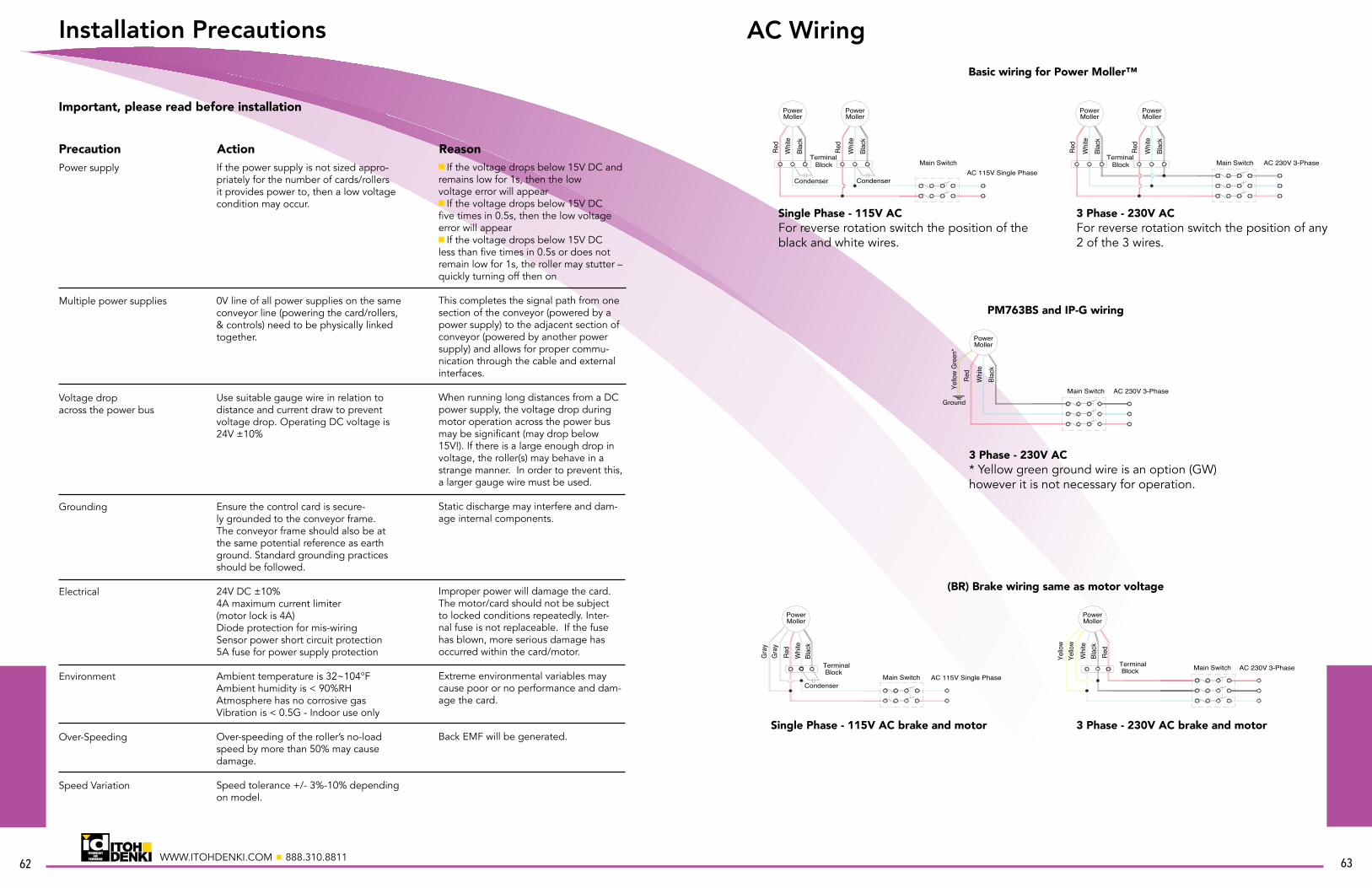
62WWW.ITOHDENKI.COM n 888.310.8811
Power supply
Multiple power supplies
Voltage drop across the power bus
Grounding
Electrical
Environment
Over-Speeding
Speed Variation
If the power supply is not sized appro-priately for the number of cards/rollers it provides power to, then a low voltage condition may occur.
0V line of all power supplies on the same conveyor line (powering the card/rollers, & controls) need to be physically linked together.
Use suitable gauge wire in relation to distance and current draw to prevent voltage drop. Operating DC voltage is 24V ±10%
Ensure the control card is secure-ly grounded to the conveyor frame. The conveyor frame should also be at the same potential reference as earth ground. Standard grounding practices should be followed.
24V DC ±10% 4A maximum current limiter (motor lock is 4A) Diode protection for mis-wiring Sensor power short circuit protection 5A fuse for power supply protection
Ambient temperature is 32~104°F Ambient humidity is < 90%RH Atmosphere has no corrosive gas Vibration is < 0.5G - Indoor use only
Over-speeding of the roller’s no-load speed by more than 50% may cause damage.
Speed tolerance +/- 3%-10% depending on model.
n If the voltage drops below 15V DC and remains low for 1s, then the lowvoltage error will appear n If the voltage drops below 15V DCfive times in 0.5s, then the low voltage error will appearn If the voltage drops below 15V DCless than five times in 0.5s or does not remain low for 1s, the roller may stutter – quickly turning off then on
This completes the signal path from one section of the conveyor (powered by a power supply) to the adjacent section of conveyor (powered by another power supply) and allows for proper commu-nication through the cable and external interfaces.
When running long distances from a DC power supply, the voltage drop during motor operation across the power bus may be significant (may drop below 15V!). If there is a large enough drop in voltage, the roller(s) may behave in a strange manner. In order to prevent this, a larger gauge wire must be used.
Static discharge may interfere and dam-age internal components.
Improper power will damage the card. The motor/card should not be subject to locked conditions repeatedly. Inter-nal fuse is not replaceable. If the fuse has blown, more serious damage has occurred within the card/motor.
Extreme environmental variables may cause poor or no performance and dam-age the card.
Back EMF will be generated.
Installation Precautions
Important, please read before installation
Precaution Action Reason
63
AC Wiring
Single Phase - 115V ACFor reverse rotation switch the position of the black and white wires.
3 Phase - 230V ACFor reverse rotation switch the position of any 2 of the 3 wires.
Basic wiring for Power Moller™
PM763BS and IP-G wiring
(BR) Brake wiring same as motor voltage
3 Phase - 230V AC* Yellow green ground wire is an option (GW) however it is not necessary for operation.
3 Phase - 230V AC brake and motorSingle Phase - 115V AC brake and motor
Red
Moller
Whi
teBl
ack
Power
Main Switch AC 230V 3-PhaseYello
w G
reen
*
Ground
PowerMoller
Red
Whi
teBl
ack
Terminal Block
Red
Moller
Whi
teBl
ack
Power
Main Switch AC 230V 3-PhaseAC 115V Single Phase
Condenser Condenser
Red
Whi
teBl
ack
Terminal Block
Red
Whi
teBl
ack
MollerPowerPower
Moller
Main Switch
AC 230V 3-PhaseMain Switch
Yello
w
Blac
kW
hite
Red
Yello
w
Red
Condenser
Blac
kW
hite
Terminal Block
Main Switch AC 115V Single Phase
Gra
yG
ray
MollerPower
MollerPower
BlockTerminal

64WWW.ITOHDENKI.COM n 888.310.8811
AC Wiring
(BR) (OS) - Brake voltage DC, motor voltage AC
(EC) - Free clutch voltage same as motor
(EC) (OS) - Free clutch voltage DC, motor voltage AC
100V DC brake; motor voltage AC
115V AC single phase free clutch and motor
100V DC free clutch, motor voltage AC
24V DC brake; motor voltage AC
230V AC 3 phase free clutch and motor
24V DC free clutch, motor voltage AC
Blac
k
Brow
n
Whi
teBr
own
Red
BlockTerminal AC 230V 3-PhaseMain Switch
DC Power Supply
Block
DC Power Supply
Blac
k
Gre
enG
reen
Whi
te
Terminal
Red
AC 230V 3-PhaseMain Switch
MollerPower
MollerPower
Blac
k
Ora
nge
Whi
teO
rang
e
Red
BlockTerminal
AC 230V 3-PhaseMain Switch
Whi
te
Gre
enG
reen
Red
Condenser
Blac
k
Main Switch AC 115V Single Phase
MollerPower
MollerPower
Terminal Block
Condenser
Terminal
DC Power Supply
Block
Blac
k
Yello
wYe
llow
Whi
te
Red
Block
DC Power Supply
Blac
k
Gra
yG
ray
Whi
te
Terminal
Red
AC 230V 3-PhaseMain SwitchAC 230V 3-PhaseMain Switch
MollerPower
MollerPower