Embed Size (px)
Citation preview
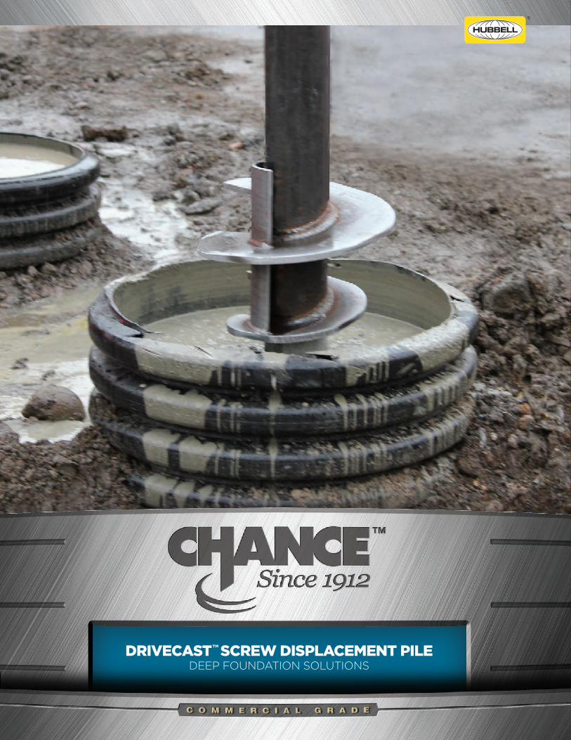
DRIVECAST™ SCREW DISPLACEMENT PILEDEEP FOUNDATION SOLUTIONS

PERMANENT FOUNDATIONS, ANYWHERE
Construct a high capacity pile, simply by installing the Drivecast pile to the required depth while maintaining a cement grout reservoir at ground surface. Gravity will naturally pull down the grout into the space provided by the displacement assembly, creating a fully encased grouted pile.
PREDICTABLE HIGH CAPACITIES
HIGH PRODUCTION RATES
NO VIBRATIONS / SPOILS
T he Drivecast™ screw displacement pile utilizes
soil displacement methodology which allows the
pile to be advanced into the soil by rotation.
Pile sections are comprised of a centralized steel shaft
and a patented displacement assembly placed at
regular intervals from the pile tip. By design, the pile
establishes a cylindrical void which allows a column of
grout to be immediately pulled down from a gravity-fed
reservoir, creating a fully grouted, high capacity pile.
CHANCE® FOUNDATION SOLUTIONS

CHANCE® FOUNDATION SOLUTIONS
INSTALLATION PROCESSDrivecast™ pile sections are engaged and advanced into the soil in a smooth, continuous manner at a rate of rotation of 5 to 20 RPM’s.
Extensions are installed for required depths can be achieved, while sufficiently applying down pressure to uniformly advance each of the sections. Sections are connected by using coupling bolts and nuts, torqued to 40 ft-lbs. The rate of rotation and magnitude of down pressure is adjusted for different soil conditions and depths.
The grout is released from a gravity-fed reservoir located at the surface, prior to the advancement of the lead section into the soil, and is continued until the minimum column length is achieved.
GROUT
Drivecast grout is typically a 4500 psi mix, either neat
or with a sand aggregate filler. Grout is placed into
the reservoir immediately prior to the advancement
of the lead section into the soil. The volume of grout
contained in the reservoir is always maintained at a
level to maintain positive hydrostatic pressure on the
grout column. Grout placement continues until the
Drivecast pile installation is completed.
MINIMAL SITE DISTURBANCE
LOW MOBILIZATION COSTS
STANDARD INSTALLATION EQUIPMENT
INSTALLATION EQUIPMENT
A rotary type, hydraulic power driven torque
motor should be utilized, along with a Kelly bar
adapter and square shaft (SS) or round shaft
(RS) drive tool. It is recommended that a torque
indicator be used to measure torque and can
be an integral part of the installation
equipment or externally mounted in-line
with the installation tooling.
Torque IndicatorSS Drive ToolRS Drive Tool

MINIMAL SITE DISTURBANCE
LOW MOBILIZATION COSTS
STANDARD INSTALLATION EQUIPMENT
APPLICATION VERSATILITYDesigned for projects where increasing capacity and providing predictable results is a must, CHANCE® Drivecast™ pile is fully grouted, resisting corrosion in aggressive soils and high water tables.
As a proven engineered system, bearing and side resistance is combined to bring a large diameter solution to a wide variety of applications for new construction, heavy highway, tanks/sewer, pipelines, and commercial/industrial buildings.
Perfect for limited access sites or areas with low overhead, this sectional, pile provides added capacity with efficient, predictable results.
* Multiple helical piles could be installed + Predrilling may be required
COMPARISON OF DEEP FOUNDATION ELEMENTS
Capacity 300k ULT Load
Capacity 675k ULT Load
Predictable Load Capacities
Ability To Install In Tight Access (5ft wide) and
Low Headroom (8ft high)
Limited or No Spoils
Limited / No Vibration, Noise
No Dewatering Required
Obstructions In Soil (Boulders, Rubble, etc.)
Caissons DrivenPiles
RammedAggreate
CFA Piles
MicroPiles
Helical Piles
Drivecast™
OPTIMAL FOR LIMITED ACCESS
AREAS WITH LOW OVERHEAD
OR LOW CLEARANCE CONDITIONS
Torsional Strength* Rating (ft-lb)
Grout Column Diameter (in)
Allowable Compressive Strength** (kip)
13,000
10
150
23,000
12
210
MECHANICAL STRENGTH RATINGS
TYPE RS35003-1/2" O.D
0.300" WALL PIPE
TYPE RS45004-1/2" O.D
0.337" WALL PIPE
TYPE SS2002" ROUND
CORNER SHAFT
TYPE SS1751-3/4" ROUND
CORNER SHAFT
10,500
8
170
16,000
12
280
*Actual installed capacities are dependent on soil conditions
**CHANCE Drivecast™ allowable compressive strength = 0.33(f'c)Ac + 0.4(Fys)As

CORROSION PROTECTIONDrivecast™ piles are offered both as uncoated or hot dip galvanized per ASTM A153 or A123. The fully grouted column itself provides one level of corrosion protection. If soil conditions, service life, or code requirements warrant additional protection, then hot dipped galvanization provides a second level of protection. Hot dipped galvanization is the only practical means to provide a corrosion resistant coating capable of withstanding the rigors of installation.
Displacement Assembly
Double Helices Configuration
DisplacementPaddle
CementGrout Column
Displacement Paddle Extends
From Central ShaftTo Outer Edge of Lower Helix
Hex HeadCoupling Bolts
Per SAE J425 Grade 5
Square S
haft (SS)
Round
Shaft (R
S)
LeadSections
Square S
haft (SS)
Round
Shaft (R
S)
ExtensionSections
Exte
nsio
n S
ectio
nL
ead
Se
ctio
n
BRIDGE/ABUTMENTS
SPORTS LIGHTING
UNDERPINNING
NEW CONSTRUCTION
SEAWALLS/SECANT WALLS
HIGHWAY LIGHTING
PIPELINE/SEWER
MIDRISE FOUNDATIONS
APPLICATIONS
PRODUCT FEATURES

ABUTMENTS SEAWALLS PIPELINE SEWERSECANT WALLS UNDERPINNING
NEW CONSTRUCTION MIDRISE STRUCTURE FOUNDATIONSBRIDGE HIGHWAY/SPORTS LIGHTING
DRIVECAST™ SCREW DISPLACEMENT PILEDEEP FOUNDATION SOLUTIONS
chancefoundationsolutions.com
Never Compromise™
CHANCE Civil Construction | 210 North Allen Street | Centralia, MO 65240 | United States of America
©Copyright 2017 Hubbell Incorporated. Because Hubbell has a policy of continuous product improvement,
we reserve the right to change design and specifications without notice.
Printed in the U.S.A. | BR_04_176_E


![Statnamic Pile Load Testing - Accueil | CFMS · · 2012-01-19Disadvantages: Difficult to ... STN Cyclic Load Displacement Diagram Displacement [mm] Load ... preparation European](https://img.dokumen.tips/doc/110x75/5ac3e0eb7f8b9a333d8cae17/statnamic-pile-load-testing-accueil-difficult-to-stn-cyclic-load-displacement.jpg)