Embed Size (px)
Citation preview

October, 2015 PUBLICATION NO. : 4H.1441.16.0.00 Rev. No. : 00
Application, Installation & Maintenance Manual
KOEL Driveshaft
FOR FIRE PUMP DRIVE ENGINES
Kirloskar Oil Engines Ltd.
Laxmanrao Kirloskar Road
Khadki, Pune (INDIA)
TEL: +91(20)25810341
FAX: +91(20) 25813208

K i r l o s k a r O i l E n g i n e s L t d . ,
Page I
Foreword Dear Customer,
We are glad to welcome you to the family of KIRLOSKAR KFP series engine owners. The
Connecting Drive shafts are specifically selected for KFP series engines for Fire fighting pump
application. These Drive shafts are UL Listed. Kirloskar products are well known for their
reliability, simplicity in the maintenance and low running cost. Prompt after sales service
through countrywide network of Service Dealers and Distributors is one of the plus point in
buying Kirloskar products.
We assure you that all necessary safety precautions and regulations have been observed in design
and selection of materials Drive shafts. All the units undergo rigorous tests before being
delivered to customer.
This manual deals with Drive shafts Installation, Operations and Maintenance. The performance
of the Drive shafts largely depends on its proper maintenance and up keep. So be sure to
maintain the Flexible Connecting Shaft properly as per the instructions given in this manual. We
recommend that only trained staff should be permitted to perform the operating and maintenance
tasks. Always use genuine KIRLOSKAR SPARE PARTS, if at all required. In addition to the
publication of this manual, we maintain facilities for training operators and owners in the
maintenance of KIRLOSKAR products. You can avail yourself of these facilities by contacting
our authorized Service Dealer/Distributor nearest to you.
Continuous improvements and advancement of product design may cause changes in products,
which may not include in the publication. Each publication is reviewed and revised as and when
required to update and include changes in later editions without notice.

K i r l o s k a r O i l E n g i n e s L t d . ,
Page II
Index
Sr. No. Topic Page No.
1
1.1
1.2
1.3
1.4
Overall 1
Introduction 1
Service and Maintenance 1
Maintenance and Repairs 1
Safety Precautions 1
2
2.1
2.2
Driveshaft Application Guidelines 2
Drive Shaft for Centrifugal Pump Driver 2
Driver Maximum Available Power Chart and Application Calculation 2
3
3.1
3.2
Installation Guidelines 3
Driveshaft Installation Procedure 3
Drive Shaft Alignment Procedure 5
4
4.1
4.2
Drive Shaft Lubrication 6
Lubrication 6
Lubrication Procedure 6
5 Dive Shaft Dimensional Data 10
6 Trouble Shooting 11

K i r l o s k a r O i l E n g i n e s L t d . ,
Page 1
1. Overall
1.1 Introduction
KOEL Driveshaft manual provides the information of the Application, installation and
maintenance of Flexible driveshaft used for diesel engine driven fire pump application. The
proper Application, installation and maintenance gives the optimum results in shaft performance
and safety.
KOEL recommend that the customer to keep the manuals with every equipment. It is
operator responsible for operation and maintenance of the equipment, Operator should read and
understand this manual thoroughly before the actual operation.
These Driveshafts should be installed in accordance with the Standard for Installation of
Stationary Pumps for Fire Protection, NFPA 20.
.
1.2 Service and Maintenance
The proper service and maintenance practices will ensure that the driveshaft continues to meet
the requirements. Recommended service intervals must be observed. The service and
maintenance work should be carried out carefully. Special care should be taken under
abnormally demanding operating conditions.
1.3 Maintenance and Repairs
Shut down the diesel engine driver before carrying out maintenance or repair work. When the
work is complete, be sure to install safety devices that may have been removed. Observe all
industrial safety regulations when diesel engine drivers are operating in enclosed spaces or
underground.
Please contact your distributor for Spare parts enquiry. Use only genuine spare parts.
1.4 Safety Precautions
The operator should read and understand the following safety precautions before the actual
operation.

K i r l o s k a r O i l E n g i n e s L t d . ,
Page 2
All Safety instructions and the attention of operating personnel should be drawn to these
instructions. General safety and accident prevention regulations laid down by law must also be
observed.
The rotating shafts can cause major injuries, so keep body parts and any loose wearing
away all the times. Follow all safety precautions during installation, maintenance and operation.
Use proper guards on rotating parts.
Remove all tools and any other material after completion of installation or maintenance
and re-install the removed guards and covers before starting the equipment.
2. Driveshaft Application Guidelines
2.1 Drive Shaft for Centrifugal Pump Driver
The Flexible Connecting Shaft selected for Engine Power Rating and Torque is as below;
Sr.
No. Driver Cylinder Drive Shaft Part Number
1 4 Cylinder 4H.1441.01.0.PR
2 6 Cylinder 4H.1441.02.0.PR
2.2 Driver Maximum Available Power Chart and Application Calculation
The selection of Flexible Connecting shaft shall be based on the rating of the driver and not the
pump. The driver power shall not exceed the maximum available power.

K i r l o s k a r O i l E n g i n e s L t d . ,
Page 3
The driveshaft maximum available power table is as below Table 1;
Flexible Connecting Shaft for Centrifugal Pump
Maximum Power (HP) Rating
Shaft Part Number Driver
Cylinder
Rated Speed (RPM)
1470 1760 2100 2200 2350 2600 3000
4H.1441.01.0.PR 4 100 108 111 117 143 151 145
4H.1441.02.0.PR 6 254 288 336 332 330 225 266
Table 1
Note:
1. The type of driver intended for use of this drive shaft is Diesel engine only.
2. The Maximum operating speed for above drive shafts is 3000 RPM
3. The service factor is applied to the calculated end use application torque. The
calculated end use application toques ask adjusted by the service factor (SF), shall not
exceed the torque rating of the drive shaft at the applicable speed.
Refer Appendix – A showing how Table 1 values are established.
3. Installation Guidelines
3.1 Driveshaft Installation Procedure
1. The mounting flange surfaces to be cleaned by removing the dirt or contaminants.
Examine the mating surfaces for any damage in the machine finish. If the mating surfaces
not cleaned properly then it can result in premature driveshaft failure.
2. Do inspection of companion flanges for proper installation.
3. Make the driveshaft compressed position and place into position between mating flanges
(Refer Figure 1). Bigger universal joint shaft assemblies are very heavy, so use proper
lifting equipment during installation. Align pilot bore boss carefully into/onto companion
flange mating diameter, then align bolt holes on driveshaft flange with holes on
companion flange. Fix the flange to driveshaft with proper hardware. Now extend the

K i r l o s k a r O i l E n g i n e s L t d . ,
Page 4
shaft at slip section until pilot bore boss aligns with companion flange pilot bore boss. the
mounting holes to be aligned and fix the flanges.
4. Tighten the fasteners with proper torque
5. All the joints are to be lubricated before start of the equipment. Do Lubrication until
lubricant appears at all four bearing cap seals properly.
6. Verify the Horizontal offset and vertical shaft operating angle as per the specification.
7. The drive shaft guard to be installed properly prior to start up the equipment.
Figure 1
Note:
1. The Drive shaft installation shall be in accordance with Standard for Installation of
Stationary Pumps for Fire Protection, NFPA 20.
2. The Maximum and Minimum Installed length of drive shaft is as below
For 4H.1441.01.0.PR : Max. length is 425 mm (16.73 Inch) and Min. length is 361 mm
(14.21 Inch)
For 4H.1441.02.0.PR : Max. length is 497 mm (19.57 Inch) and Min. length is 453 mm
(17.83 Inch)

K i r l o s k a r O i l E n g i n e s L t d . ,
Page 5
The tightening Torque Specification for Companion Flange is as below
Driveshaft
Part Number Bolt Size Grade (Class) Torque
4H.1441.01.0.PR M10 - 1.5 8.8 47 N-m (35 lb – ft)
4H.1441.02.0.PR M12 - 1.75 8.8 75 N-m (55 lb – ft)
3.2 Drive Shaft Alignment Procedure
The drive shaft alignment procedure is based on a fire pump installation guidelines where the
engine crankshaft centerline and the pump centerline is same when viewed from the top and
parallel in the front view (Refer Figure 2). For the measurement of misalignment dial indicator or
angle meter or vernier caliper will be needed.
Figure 2
Note:
1. Maximum permitted Vertical angular misalignment is 1 +/-1 Deg and
Horizontal(Parallel)) misalignment is 0 +/-1 Deg
2. It is recommended that the torsional analysis need to conduct on the actual fire pump set
arrangement but not on only engine

K i r l o s k a r O i l E n g i n e s L t d . ,
Page 6
For service and parts inquiries, please contact to:
Kirloskar Oil Engines Ltd.
Laxmanrao Kirloskar Road
Khadki, Pune (INDIA)
TEL: +91(20)25810341
FAX: +91(20) 25813208
Email : [email protected]
Please provide the Driveshaft Serial Number or Engine serial number information.
Visit us on the web at: www.koel.co.in
4. Drive Shaft Lubrication
4.1 Lubrication
Every drive shaft needs some sort of lubrication due to rotating motion. Many times, the
premature failures of universal joint (UJ kit) and slip spline are due to lack of lubrication or
improper lubrication. The proper and regular lubrication practice removes contaminants from the
bearings resulting into maximum functional life. It is recommended to use high quality greases
with Multi-purpose Extreme Pressure Lithium Complex grease containing corrosion and
oxidation inhibitors, E.P. and anti-wear additives.
The lubrication intervals may vary depending on the drive shaft application, installation and
operating conditions. As Fire pump application is not continuous duty operation, so the
lubrication can be done at every 5- 6 months interval for indoor operating conditions and every
60 days open condition operations.
4.2 Lubrication Procedure
1. Before doing the lubrication, clean the sleeve yoke grease nipple and surrounding area to
remove dust, dirt etc. with cloth / water jet.
K i r l o s k a r O i l E n g i n e s L t d . ,
Page 7
2. Purge all four bearing seals of the universal joint kit through nipple fitting which flushes
all contaminants from each bearing assembly and apply grease gun to the grease nipple.
Ensure that all four nipples are filled completely shown below.

K i r l o s k a r O i l E n g i n e s L t d . ,
Page 8
3. Similarly lubricate the splines through nipple on shaft assembly as shown below.
Continue greasing with grease gun till the grease comes out of air vent hole in sleeve
yoke plug.

K i r l o s k a r O i l E n g i n e s L t d . ,
Page 9
K i r l o s k a r O i l E n g i n e s L t d . ,
Page 10
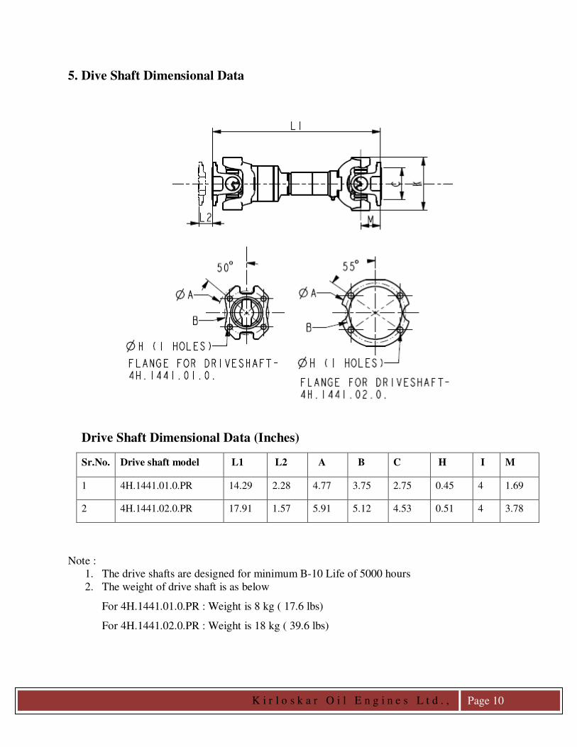
5. Dive Shaft Dimensional Data
Drive Shaft Dimensional Data (Inches)
Sr.No. Drive shaft model L1 L2 A B C H I M
1 4H.1441.01.0.PR 14.29 2.28 4.77 3.75 2.75 0.45 4 1.69
2 4H.1441.02.0.PR 17.91 1.57 5.91 5.12 4.53 0.51 4 3.78
Note :
1. The drive shafts are designed for minimum B-10 Life of 5000 hours
2. The weight of drive shaft is as below
For 4H.1441.01.0.PR : Weight is 8 kg ( 17.6 lbs)
For 4H.1441.02.0.PR : Weight is 18 kg ( 39.6 lbs)

K i r l o s k a r O i l E n g i n e s L t d . ,
Page 11
6. Trouble Shooting
Trouble Cause Solution
VIBRATIONS Drive shaft yokes not in phase Disassemble and re-align yoke.
Driver or driven components out
of balance. Consult equipment manufacturer.
Drive shaft exceeding maximum
joint acceleration.
Reduce the operating angle and/or
speed.
Drive shaft operating near critical
or half critical speed resonance
Consult equipment manufacturer.
Flange faces not seated. Remove drive shaft fasteners and
check for burrs or dirt. Reassemble
the shaft with tightening torque for
all fasteners.
Operating at or near driver or
driven equipment natural
frequency.
Consult with equipment
manufacturer.
Operating speed is within a
torsional vibration mode.
Carry out the torsional analysis.
Consult equipment manufacturer
for assistance.
Driver and driven
shaft/Companion flange not
parallel within 1Degree.
Re-align and re-adjust any of
these, Add shims if necessary.
Dry or brinelled (needle bearing
indentations)
Replace defective joints or check
lubrication. Review operating
parameters.
Driver and driven shaft run-out Consult engine manufacturer.
Excessive radial movement at the
slip yoke
Lack of lubrication, overload
condition. Consult with equipment
manufacturer.
Companion flange, fastener loose. Tighten the fastener or Check for
vibrations
Drive system resonance/vibration Perform vibration analysis. Consult
equipment manufacturer.
Pump noise. Consult pump manufacturer.
FLANGE LOOSE
ON DRIVESHAFT
Companion Flange fasteners or
Set screw over keyway not
tightened properly.
Reassemble fasteners/set screw
properly.
Weight limitations exceeded for
flange bored or shaft diameter
undersized.
Use additional set screw or replace
flange with interference fit bore.

K i r l o s k a r O i l E n g i n e s L t d . ,
Page 12
Appendix - A
Flexible Connecting Shaft for Centrifugal Pump
Maximum Torque (lb-ft) Rating
Shaft Part Number
Driver
Cylinder
Engine Rated Speed(RPM)
1470 1760 2100 2200 2350 2600 3000
4H.1441.01.0.PR 4 715 645 555 559 639 610 508
4H.1441.02.0.PR 6 1361 1289 1260 1189 1106 682 699
Rated Torque = Max Torque
Rated HP = Rated Torque x RPM
5252
Service Factor (SF)
Service Factor (SF) = 1.5 ( Diesel Engine - 6 or more cylinders)
Service Factor (SF) = 2.0 ( Diesel Engine - 5 or less cylinders)


![POWER DRIVE PTO DRIVE SHAFT SERIES P 300 – … · power drive pto drive shaft series p 300 ... power drive pto drive shaft series with full guard and without ... (inlb) p [kw] (hp)](https://img.dokumen.tips/doc/110x75/5b5ca9cb7f8b9a3a718cbcff/power-drive-pto-drive-shaft-series-p-300-power-drive-pto-drive-shaft-series.jpg)