Embed Size (px)
Citation preview
Dresser Pipeline Solutions Valves for gas distribution piping systems
Dresser Pipeline Solutions

2
■■ Maintenance-free service with permanent lubrication at the factory
■■ Low operating torque for no plug “freezing”■■ 100% shutoff; 360° turn or 90° open left operation■■ Tamper-proof design■■ No leakage to the atmosphere■■ Coverage of full pressure range with one valve
Style 175 GTO Threaded Gas Valve FIPS x FIPSGas-Tight, Maintenance-Free, and Permanently Lubricated
Designed to meet the requirements of ANSI B16.33 1981, the Dresser Natural Gas Solutions (NGS) Style 175 GTO gas service valve incorporates the same complementary sealing principles as the Style 175 meter curb valve, yet offers a rated working pressure to 175 psig. Each GTO valve is 100% factory-tested at high and low pressure while in a clear, non-corrosive fluid.
Like the Style 175 meter curb valve, the GTO is assembled at the factory and sealed against tampering by a spring-loaded stainless steel retaining ring that cannot be removed with ordinary tools. It is tamper proof as specified in D.O.T. 192.363 Part C.
A TFE coated retaining ring, plus permanently lubricated port seals, help ensure low, uniform operating torque, preventing the plug from freezing to the body.
Material Specifications
Body and Bonnet Cast Gray Iron - ASTM A126 Class B (Semi Steel)
Plugs 3/4”, 1”, 1-1/4” and 1-1/2” Aluminum Alloy
2” Plug Cast Gray Iron - ASTM A126 Class B (Semi Steel)
Elastomer Seal Molded, Permanently Lubricated
Elastomer Seal Inserts
Elastomer, Bonded to C-1018 Steel Plate
Retainer Ring TFE Coated Type 304 Stainless Steel
Bonnet Seal O-Ring Buna S for Gas Service Applications
Spring Oil-Tempered Steel to ASTM A-229 Specifications
Style 175 GTO Size Specifications
Nom Size A B C
3/4” 4-13/16” 3” 3-1/16”
1” 5-5/16” 3-5/8” 3-17/32”
1-1/4” 5-3/16” 4-9/16” 3-7/8”
1-1/2” 6-7/16” 5-5/32” 4-7/32”
2” 6-15/16” 5-23/32” 4-1/2”
A
C
B
Stainless SteelRetaining Ring
Bonnet with“O” Ring Seal
Steel Spring
Elastomeric SteelInserts
Tapping Boss(for testing purposes)
• Elastomeric port seals have a compounded-in lifetime lubricant.
• Spring loading of the plug assures automatic plug adjustment. There are no retaining nuts to tighten or replace.
• An O-ring provides a gas-tight seal at the top. There is no bottom opening.
• A permanent bubble-tight seal is achieved by the interaction of two
3
■■ Maintenance-free service with permanent lubrication at the factory
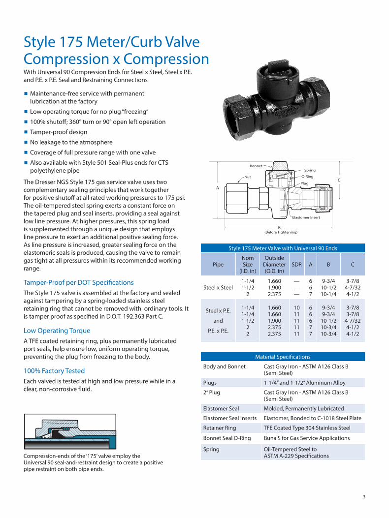
■■ Low operating torque for no plug “freezing”■■ 100% shutoff; 360° turn or 90° open left operation■■ Tamper-proof design■■ No leakage to the atmosphere■■ Coverage of full pressure range with one valve■■ Also available with Style 501 Seal-Plus ends for CTS polyethylene pipe
Style 175 Meter/Curb Valve Compression x CompressionWith Universal 90 Compression Ends for Steel x Steel, Steel x P.E. and P.E. x P.E. Seal and Restraining Connections
Material Specifications
Body and Bonnet Cast Gray Iron - ASTM A126 Class B (Semi Steel)
Plugs 1-1/4” and 1-1/2” Aluminum Alloy
2” Plug Cast Gray Iron - ASTM A126 Class B (Semi Steel)
Elastomer Seal Molded, Permanently Lubricated
Elastomer Seal Inserts Elastomer, Bonded to C-1018 Steel Plate
Retainer Ring TFE Coated Type 304 Stainless Steel
Bonnet Seal O-Ring Buna S for Gas Service Applications
Spring Oil-Tempered Steel to ASTM A-229 Specifications
Style 175 Meter Valve with Universal 90 Ends
PipeNom Size
(I.D. in)
Outside Diameter (O.D. in)
SDR A B C
Steel x Steel1-1/4 1-1/2
2
1.660 1.900 2.375
— — —
6 6 7
9-3/4 10-1/2 10-1/4
3-7/8 4-7/32 4-1/2
Steel x P.E.
and
P.E. x P.E.
1-1/4 1-1/4 1-1/2
2 2
1.660 1.660 1.900 2.375 2.375
10 11 11 11 11
6 6 6 7 7
9-3/4 9-3/4
10-1/2 10-3/4 10-3/4
3-7/8 3-7/8
4-7/32 4-1/2 4-1/2
The Dresser NGS Style 175 gas service valve uses two complementary sealing principles that work together for positive shutoff at all rated working pressures to 175 psi. The oil-tempered steel spring exerts a constant force on the tapered plug and seal inserts, providing a seal against low line pressure. At higher pressures, this spring load is supplemented through a unique design that employs line pressure to exert an additional positive sealing force. As line pressure is increased, greater sealing force on the elastomeric seals is produced, causing the valve to remain gas tight at all pressures within its recommended working range.
Tamper-Proof per DOT Specifications The Style 175 valve is assembled at the factory and sealed against tampering by a spring-loaded stainless steel retaining ring that cannot be removed with ordinary tools. It is tamper proof as specified in D.O.T. 192.363 Part C.
Low Operating TorqueA TFE coated retaining ring, plus permanently lubricated port seals, help ensure low, uniform operating torque, preventing the plug from freezing to the body.
100% Factory TestedEach valved is tested at high and low pressure while in a clear, non-corrosive fluid.
Compression-ends of the ‘175’ valve employ the Universal 90 seal-and-restraint design to create a positive pipe restraint on both pipe ends.
B
C
A
Elastomer Insert
(Before Tightening)
BonnetSpring
O-Ring
Plug
Nut
4
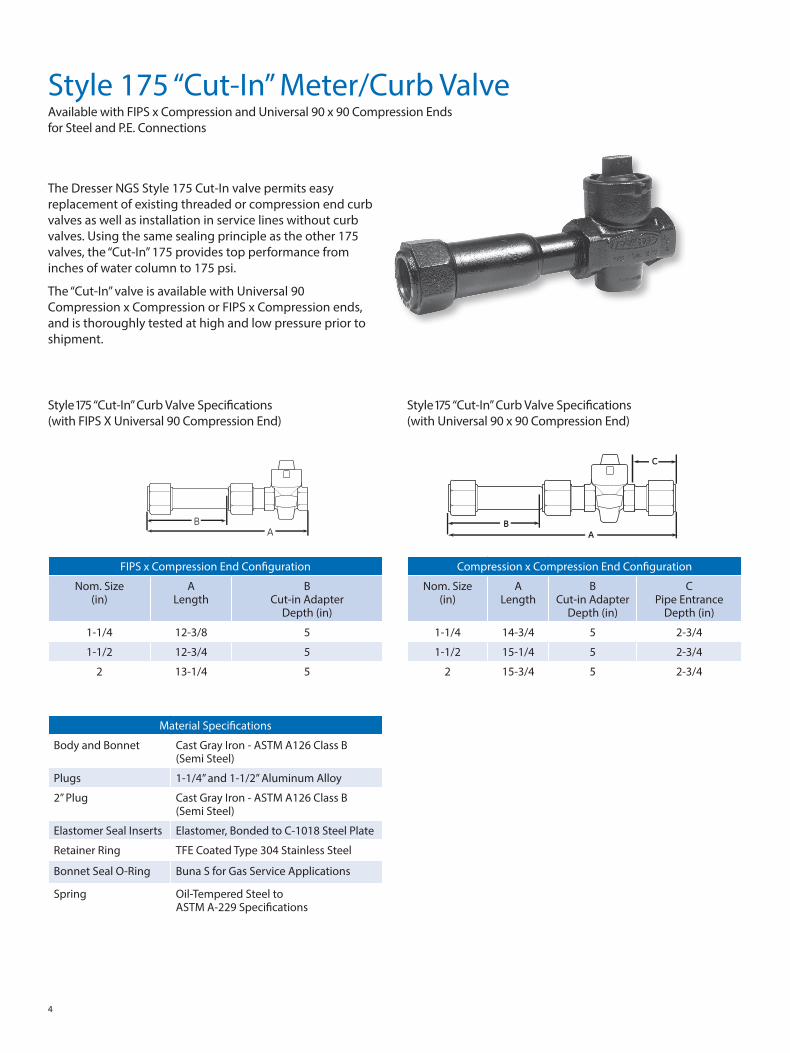
Style 175 “Cut-In” Meter/Curb ValveAvailable with FIPS x Compression and Universal 90 x 90 Compression Ends for Steel and P.E. Connections
The Dresser NGS Style 175 Cut-In valve permits easy replacement of existing threaded or compression end curb valves as well as installation in service lines without curb valves. Using the same sealing principle as the other 175 valves, the “Cut-In” 175 provides top performance from inches of water column to 175 psi.
The “Cut-In” valve is available with Universal 90 Compression x Compression or FIPS x Compression ends, and is thoroughly tested at high and low pressure prior to shipment.
Style 175 “Cut-In” Curb Valve Specifications (with FIPS X Universal 90 Compression End)
FIPS x Compression End Configuration
Nom. Size (in)
A Length
B Cut-in Adapter
Depth (in)
1-1/4 12-3/8 5
1-1/2 12-3/4 5
2 13-1/4 5
Compression x Compression End Configuration
Nom. Size (in)
A Length
B Cut-in Adapter
Depth (in)
C Pipe Entrance
Depth (in)
1-1/4 14-3/4 5 2-3/4
1-1/2 15-1/4 5 2-3/4
2 15-3/4 5 2-3/4
Style 175 “Cut-In” Curb Valve Specifications (with Universal 90 x 90 Compression End)
Material Specifications
Body and Bonnet Cast Gray Iron - ASTM A126 Class B (Semi Steel)
Plugs 1-1/4” and 1-1/2” Aluminum Alloy
2” Plug Cast Gray Iron - ASTM A126 Class B (Semi Steel)
Elastomer Seal Inserts Elastomer, Bonded to C-1018 Steel Plate
Retainer Ring TFE Coated Type 304 Stainless Steel
Bonnet Seal O-Ring Buna S for Gas Service Applications
Spring Oil-Tempered Steel to ASTM A-229 Specifications
AB
C
A B

5
■■ Permanent lubrication is installed at the factory for maintenance-free service.
■■ The valve body and plug are high grade malleable or ductile iron.
■■ The design is tamper proof.■■ The valve stem is dual O-Ring sealed. One O-Ring provides a positive pressure seal to the atmosphere, while the other seals against moisture intruding between the body and bonnet.
■■ The bottom of the valve body is solid, eliminating any leak path to the atmosphere.
■■ The lock-wing is an integral part of the plug.■■ Each valve body features a boss to accommodate a 1/8” IPS tap for testing.
■■ The valve meets all requirements of ANSI B 16.33-81 and conforms to D.O.T. 192.
Style 275 Meter ValveA Compact, Economical Gas Meter Valve
The Dresser NGS Style 275 gas meter valve is a maintenance-free, compact and reliable positive shutoff valve. Rated for operating pressures from inches of water column to 175 psig, the Style 275 is available in sizes 3/4”, 1” and 1-1/4”, lock-wing FIPS, and insulated union lock-wing configurations.
Operating PrincipleThe Style 275 incorporates a spring-loaded seat, plus a self-sealing feature that increases sealability as operating pressure increases. At low pressures, the leaf-type springs exert pressure to force the elastomeric-coated insert seals into a positive sealing position.
At higher pressures, the valve is designed to employ the gas line pressure to impose a supplemental compressive loading against the seals. The higher the line pressure, the greater the sealing force. Since this force can be exerted on either seal, the valve is non-directional.
Standard CoatingThe Style 275 is supplied with an ecoat or zinc phosphate finish as standard that can be used as either the prime coat or the sole coating, depending on service conditions. Salt-spray tests have shown these coatings to provide excellent corrosion resistance.
X Y
A
B
C
D
E
Style 275 Meter Valve Specifications
Size X & Y (in)
A (in)
B (in)
C (in)
D (in)
E (in)
3/4 3-3/8 23/32 2-17/32 1-5/8 1-7/8
1 3-7/8 3/4 2-29/32 1-13/16 2-1/8
1-1/4 4-1/4 13/16 3-11/32 2-1/32 2-7/16
Style 275 Meter Valve Specifications with Insulated Union End
Size X & Y (in)
A (in)
B (in)
C (in)
D (in)
E (in)
3/4 5-25/32 23/32 2-17/32 1-5/8 1-7/8
1 6-5/8 3/4 2-29/32 1-13/16 2-1/8
1-1/4 7 13/16 3-11/32 2-1/32 2-7/16
3/4x1-1/4 7 13/16 3-11/32 2-1/32 2-7/16
Material Specifications
Body and Stem Bonnet
High Grade Malleable or Ductile Iron
Weather Seal O-Ring Buna N Rubber
Stem Seal O-Ring Buna S Rubber
Retaining Seats Buna N Rubber
Retaining Seat Pads Ferrous Powder Metal
Retainer Seat Spring Type 304 Stainless Steel
B
A
D
C
XY
E
Tail Piece
Nut
O-Ring
Insulator 275 Valve Body
Stem O-RingWeather SealO-Ring
Seat SealSteel Seat Spring
6
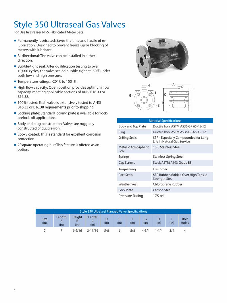
Style 350 Ultraseal Gas ValvesFor Use In Dresser NGS Fabricated Meter Sets
■■ Permanently lubricated: Saves the time and hassle of re-lubrication. Designed to prevent freeze-up or blocking of meters with lubricant.
■■ Bi-directional: The valve can be installed in either direction.
■■ Bubble-tight seal: After qualification testing to over 10,000 cycles, the valve sealed bubble-tight at -30°F under both low and high pressure.
■■ Temperature ratings: -20° F. to 150° F.■■ High flow capacity: Open position provides optimum flow capacity, meeting applicable sections of ANSI B16.33 or B16.38.
■■ 100% tested: Each valve is extensively tested to ANSI B16.33 or B16.38 requirements prior to shipping.
■■ Locking plate: Standard locking plate is available for lock-on/lock-off applications.
■■ Body and plug construction: Valves are ruggedly constructed of ductile iron.
■■ Epoxy coated: This is standard for excellent corrosion protection.
■■ 2” square operating nut: This feature is offered as an option.
Material Specifications
Body and Top Plate Ductile Iron, ASTM A536 GR 65-45-12
Plug Ductile Iron, ASTM A536 GR 65-45-12
O-Ring Seals SBR - Especially Compounded for Long Life in Natural Gas Service
Metallic Atmospheric Seal
18-8 Stainless Steel
Springs Stainless Spring Steel
Cap Screws Steel, ASTM A193 Grade B5
Torque Ring Elastomer
Port Seals SBR Rubber Molded Over High Tensile Strength Steel
Weather Seal Chloroprene Rubber
Lock Plate Carbon Steel
Pressure Rating 175 psi
Style 350 Ultraseal Flanged Valve Specifications
Size (in)
Length A
(in)
Height B
(in)
Center C
(in)
D (in)
E (in)
F (in)
G (in)
H (in)
I (in)
Bolt Holes
2 7 6-9/16 3-11/16 5/8 6 5/8 4-3/4 1-1/4 3/4 4
AH
G
F
E
D
C
B
I

7
Style 575 Angle Ball ValveAll-in-One Service Tee Connection and Shutoff Valve
The Dresser NGS Style 575 Angle Ball valve provides dual service, as a main-to-service compression end tee connection and as a shutoff valve.
Constructed of a unique combination of a rugged ductile iron body and a high-strength engineered plastic plug, the 575 valve offers a low torque 90-degree operation with positive, bottle-tight shutoff at pressures up to 125 psi. Designed for durability under all service conditions, the valve features an interface of ductile and engineered plastic components, eliminating the possibility of valve freeze-up due to corrosion.
The 575 valve also eliminates the presence of an isolated metallic valve in a plastic service. The ductile material in the valve body is compatible with the cast iron main, so there’s no need for anoding and monitoring. Plus, an optional Dresser NGS Plastisol* coating from Dresser NGS can provide even greater external corrosion protection.
The compression end for connecting the service is of a time-proven Dresser NGS design and meets all the requirements of D.O.T. 192.283(b), providing a permanent seal and pull-out resistance greater than the P.E. tubing in tension.
The 575 valve is available in inlet sizes 1-1/4” or 1-1/2” MIPT and an outlet size of 1-1/8” OD.
Style 575Valve
Gas Main
PE Service
Eliminates Isolated Valves
Item Description1 Body2 Bonnet Cap3 Valve Plug4 Moisture Seal5 Retainer Ring6 O-Ring7 Branch Gasket8 Seat Gasket9 Valve Branch
10 Gasket Retainer
B
A
B
A
Style 575 with Shield Nut
Style 575 Angle Ball Valve Specifications
Pipe Size Inlet x Branch
(in)
Tubing Wall
Thickness (in)
A Length
501 End (in)
A Length w/Shd
Nut (in)
B Overall Height
(in)
1-1/4 MIPT x 1-1/8 OD .090 5-1/4 5-7/8 4-7/8
1-1/2 MIPT x 1-1/8 OD .090 5-1/4 5-7/8 4-7/8

Dresser Pipeline Solutions41 Fisher AvenueBradford, PA 16701T: 814.362.9200F: 814.362.9344
© 2018 Natural Gas Solutions North America, LLC – All rights reserved. Natural Gas Solutions reserves the right to make changes in specifications and features shown herein, or discontinue the product described at any time without notice or obligation. Contact your Dresser Natural Gas Solutions representative for the most current information. The Dresser Logo and all Trademarks containing the term “Dresser” are the property of Dresser, LLC, a subsidiary of Baker Hughes, a GE Company. www.dresserngs.com
Dresser Valves For Gas Brochure NGS.DPS.004
10.18
![INDEX [] and Machinery... · ansi standard 1792–1816 ... ansi b4.2 642, 644, 646, 648–655, 657. index 2559 ansi b4.4m 656 ansi b47.1 1882 ansi b5.18 920, 922–924 ansi b6. 7](https://img.dokumen.tips/doc/110x75/5aa7faa47f8b9aee748cbd3f/index-and-machineryansi-standard-17921816-ansi-b42-642-644-646.jpg)


![Manually Operated Metallic Gas Valves for Use in Gas ...files.asme.org/Catalog/Codes/PrintBook/33064.pdf · ASME B16.33-2012 [Revision of ASME B16.33-2002 (R2007)] Manually Operated](https://img.dokumen.tips/doc/110x75/5e4424a5514494245a4ad269/manually-operated-metallic-gas-valves-for-use-in-gas-filesasmeorgcatalogcodesprintbook33064pdf.jpg)