Embed Size (px)
Citation preview

1
TALGIL COMPUTING & CONTROL LTD.
NAAMAN CENTER, HAIFA - ACCO ROAD ISRAEL
P.O. BOX 775 KIRYAT MOTZKIN 26119 TEL: 972-4-9506050 - 9506051
FAX: 972-4-8775949
February 2016
DREAM 2
INSTALLATION GUIDE

2
Table of Contents
1. THE SYSTEM STRUCTURE ........................................ 4 1.1 Looking inside the DREAM 2 case ................................................................. 5
1.1.1 The Power Supply board.................................................................................... 7 1.1.2 The Mother Board .............................................................................................. 8 1.1.3 The CPU board .................................................................................................. 9
2. SWITCHING UP AND SHUTTING DOWN ................. 10 2.1 Switching Up .................................................................................................. 10 2.2 Shutting Down ................................................................................................ 11
3. THE INTERNET COMMUNICATION .......................... 12 3.1 Communication through Ethernet ................................................................ 13 3.2 Communication through Modem or Netstick .............................................. 15
4. THE SYSTEM MANAGEMENT SCREENS ................ 16 4.1 General ............................................................................................................ 16 4.2 Network ........................................................................................................... 17 4.3 Logging ........................................................................................................... 19 4.4 Service ............................................................................................................ 19 4.5 Update ............................................................................................................. 20 4.6 Modem ............................................................................................................. 22 4.7 System ............................................................................................................ 23
5. THE VARIOUS I/O OPTIONS ................................... 23 5.1 Interface for local I/O AC or DC .................................................................... 23
5.1.1 I/O expansion and Remote I/O ........................................................................ 24 5.2 Interface for single cable 2 wired RTUs ....................................................... 27 5.3 Interface for radio communicated RTUs...................................................... 28 5.4 Interfaces for local analog inputs ................................................................. 28 5.5 Interface pH/EC (Fertmaster) ........................................................................ 30 5.6 THD Interface .................................................................................................. 31 5.7 Weather station Interface .............................................................................. 32
6. LIGHTNING PROTECTION ....................................... 33 6.1 Lightning protection for the 2W single cable system ................................ 34 6.2 Lightning protection for RS485 communication line ................................. 34 6.3 Lightning protection for 16 AC outputs ....................................................... 34 6.4 The enclosures of the DREAM system ........................................................ 35
7. INSTALLATION STEPS ............................................. 35 7.1 Mounting the controller ................................................................................. 36 7.2 Defining the configuration ............................................................................ 37
7.2.1 The network definition..................................................................................... 40 7.2.2 The hardware definition ................................................................................... 44 7.2.3 CONNECTIONS DEFINITION ...................................................................... 45
7.3 Testing operation of inputs and outputs ..................................................... 48 7.3.1 Testing the outputs ........................................................................................... 48 7.3.2 Testing the inputs ............................................................................................. 48 7.3.3 What comes next? ............................................................................................ 49
8. THE DREAM SIMULATION SOFTWARE .................. 50
9. SUPPLEMENTARY DEVICES ................................... 51 9.1 Switching electric pumps .............................................................................. 51 9.2 The three functions of the REBRAN board ................................................. 55
9.2.1 RS485 Repeater with optic isolation ................................................................ 55 9.2.2 2 or 4 Analog inputs interface ......................................................................... 56 9.2.3 RS485 Bridge............................................................................................... 57
9.3 The pulses divider.......................................................................................... 57

3
9.3.1 The Push Buttons ............................................................................................. 59 9.3.2 LED indicators ................................................................................................. 59 9.3.3 The Jumper ...................................................................................................... 59
10. APPENDIXES ............................................................ 60 10.1 Appendix “A” – Decimal to Binary conversion ........................................ 60 10.2 Appendix "B" – Rules about cables ............................................................ 61
10.2.1 CABLE RESISTANCE TESTING................................................................ 61

4
1. THE SYSTEM STRUCTURE
The DREAM 2 irrigation control system is the second generation of the well-known DREAM controllers. Additionally to the outstanding features of the previous generation, the DREAM 2 is now equipped with a more powerful processor, with a much bigger memory capacity and above all it now offers internet communication, supported by a powerful SERVER. Users and technicians can now access the controllers from everywhere anytime. Upgrading from DREAM 1 to DREAM 2 is involved with replacement of three boards only: the CPU, the Mother board and the Power supply board.
The following schematic diagram describes the principal structure of the DREAM 2 system which apart from the internet communication resembles very much the structure of DREAM 1.

5
The heart of the system is the CPU board, which is in charge of all the decision making of the controller. The decision making procedure is based on the logic included in the firmware, the configuration defined by the installer, the programs defined by the user and the current status of the devices connected to the controller, inputs and outputs. The input devices consist of sensors that supply information to the CPU and the output devices are those that are activated by the commands generated by the CPU. However the CPU does not interact directly with the input/output devices comprising the irrigation network, for that purpose various kinds of I/O (Inputs/Outputs) Interfaces are used. The I/O Interfaces will usually use the services of various I/O boards or RTUs that really execute the output commands and read the input sensors. The CPU communicates with all the I/O Interfaces second by second, sending them the desired status of outputs and receiving back the status of the inputs. The schematic drawing above shows the various kinds of Interfaces recognized by the DREAM 2 system. A control system will include an arbitrary combination of these Interfaces; some controllers may include several Interfaces of the same type. The communication channel between the CPU and the Interfaces uses the RS485 protocol which enables communication up to a distance of several kilometers on a two wired line; this enables placing interfaces distantly from the CPU when needed. Another function of the CPU is the communication with the external world. This is done through the internet, utilizing the SERVER which is located somewhere in the cloud. The way to set up the communication channel will be described below.
1.1 Looking inside the DREAM 2 case
Location of the
backup battery
AC power
supply board
Transformer
Motherboard
Local I/O
interface
Local I/O
board 16/8 RF interface

6
The picture above shows the inner part of a DREAM 2 controller. It must be pointed out that due to the flexible structure of the DREAM 2 system, the construction of a controller may vary from one case to another, depending on the specific needs. In our example it can be seen that the controller is of the type powered from the mains through the transformer. We can see the Power supply board that is in charge of generating the various types of voltages used in the system. We can see the Mother board which combines the various parts of the system together. Plugged into the bottom of the Mother board, there are two interfaces, one is the Local I/O Interface and the other is the RF Interface. The Local I/O Interface is in charge of the Local I/O boards, in this example there is one Local I/O board 16/8 (16 outputs and 8 inputs). The RF Interface is coordinating between the CPU and the Master receiver transmitter which is in charge of the communication with the radio RTUs in the field. To demonstrate the flexibility of the DREAM 2 system we shall bring another example of a controller which is designed for powering by solar energy (it does not contain a transformer) its power supply board is of the DC type and in this case the local I/O interface controls two Local I/O boards 16/8 that makes 32 local outputs and 16 local inputs. When the system contains more interfaces than can be plugged into the mother board, they will be installed externally and they will be connected by two wires to the Remote I/O plug (RS485) on the mother board for communication and by another two wires to an energy source of 12v DC.
DC power
supply board
Local I/O
interface
Local I/O
board 16/8 Local I/O
board 16/8
Remote I/O
plug

7
1.1.1 The Power Supply board
The drawing above shows the two options of power supply boards. The one on the left is the DC type, it is used for powering from solar energy and the one on the right is the AC type to be used for powering from the mains. From the moment of connection to the energy source, the yellow LED which indicates the existence of the charging voltage (13.9v DC) for the backup battery should be lighting constantly, even before the Power Switch is turned on. If it does not light, check the charging source and check the Charging Fuse. The red LED of 24v AC (in AC models) will start lighting when the Power Switch is turned on. If this does not happen, the Main Power Fuse has to be checked. The green LED of 12v DC will start lighting when the Power Switch is turned on. The 12v DC is used for feeding all the electronic boards of the system; it may be generated either from the charging source or from the backup battery, when the charging source is off. The system is protected from excess current consumption by the 12v DC Fuse.
Main power fuse
Charging fuse
12v DC fuse
Power switch
Start button
24 v AC
Charging
12 v DC
USB
Charge voltage
adjust
Charge limit
resistor
Outputs current
sampling resistor
DC AC
USB 12 v DC
Charging

8
Notice that:
The charging current passes through both the Charging Fuse and the 12v DC Fuse, so if for some reason the 12v DC fuse is blown, there will be no battery charging, although the charging voltage exists (yellow LED ON).
The backup battery should never left to be deeply discharged, it may harm the battery, therefore if the charging source is expected to be disconnected for a long period, the backup battery has to be disconnected as well, otherwise when the charging is restarted, the deeply discharged battery may draw a high charging current that may cause over heating of the Charge limit resistor or even blow the Charging Fuse (F3).
The red LED of the USB will start lighting only after the Start Button is pushed, indicating that the system is now up and running. Together with the USB LED of the power supply board, the red LED on the Mother Board and the three red power LEDs on the CPU Board will start lighting as well.
The procedure of switching up and shutting down the DREAM 2 controller are explained in details at paragraph 1.2 below.
1.1.2 The Mother Board The following drawing shows the main components of the Mother board:
At the right side there are two green sockets from which 12v DC can be obtained. This voltage is available after the Start Button has been pushed and as long as the DREAM 2 application has not been shut down by the Shut Down command. The Remote I/O RS485 sockets (blue and orange) are the connection points of the two wired peripheral communication lines to all the interfaces which are installed externally to the DREAM 2 case. Here the polarity is important The P and N wires should not be mixed.
12 v DC
sockets
12 v DC
LED
USB
socket
USB
LED
Ethernet
internal
Ethernet
external
Remote I/O RS485
addresses 1 to 16
Remote I/O RS485
addresses 17 to 32

9
The USB socket can be used for connecting USB memory sticks for uploading/downloading the image files into the controller or for updating the software version. Another use of the USB socket will be for connection of a Netsctick for cellular communication (see below). In case the communication is meant to be through the Ethernet or LAN (Local Area Network), the two Ethernet sockets will be used. The internal socket is for connection between the Mother board and the Ethernet card (attached on top of the CPU board), the external socket is for the cable that goes to the Ethernet source on site.
1.1.3 The CPU board
The CPU board can be found underneath the front panel, at the back of the LCD display. Let’s get familiar with some of the components on the CPU board: The Cellular modem and the Ethernet card are two of the three options for connection to the internet. The third is a USB Netstick that can be plugged into the Mother board. The Lithium battery keeps the internal clock running while the CPU board is disconnected from energy source.
Ethernet card
Reset button
LCD contrast
adjustment
Power ON
indication LEDs
Remote I/O
communication LEDs
Buzzer
CPU board
Cellular modem
The CPU chip
Lithium battery
USB Netstick
10
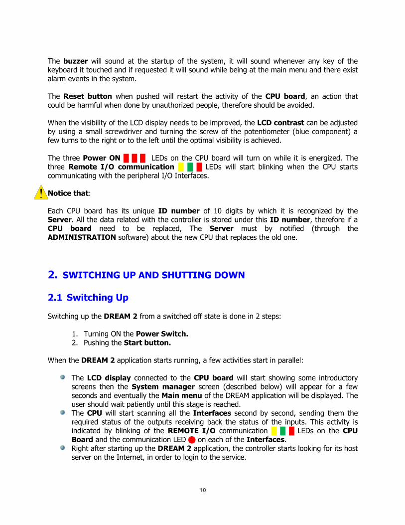
The buzzer will sound at the startup of the system, it will sound whenever any key of the keyboard it touched and if requested it will sound while being at the main menu and there exist alarm events in the system. The Reset button when pushed will restart the activity of the CPU board, an action that could be harmful when done by unauthorized people, therefore should be avoided. When the visibility of the LCD display needs to be improved, the LCD contrast can be adjusted by using a small screwdriver and turning the screw of the potentiometer (blue component) a few turns to the right or to the left until the optimal visibility is achieved. The three Power ON LEDs on the CPU board will turn on while it is energized. The three Remote I/O communication LEDs will start blinking when the CPU starts communicating with the peripheral I/O Interfaces. Notice that:
Each CPU board has its unique ID number of 10 digits by which it is recognized by the Server. All the data related with the controller is stored under this ID number, therefore if a CPU board need to be replaced, The Server must by notified (through the ADMINISTRATION software) about the new CPU that replaces the old one.
2. SWITCHING UP AND SHUTTING DOWN
2.1 Switching Up Switching up the DREAM 2 from a switched off state is done in 2 steps:
1. Turning ON the Power Switch. 2. Pushing the Start button.
When the DREAM 2 application starts running, a few activities start in parallel:
The LCD display connected to the CPU board will start showing some introductory screens then the System manager screen (described below) will appear for a few seconds and eventually the Main menu of the DREAM application will be displayed. The user should wait patiently until this stage is reached.
The CPU will start scanning all the Interfaces second by second, sending them the required status of the outputs receiving back the status of the inputs. This activity is indicated by blinking of the REMOTE I/O communication LEDs on the CPU Board and the communication LED on each of the Interfaces.
Right after starting up the DREAM 2 application, the controller starts looking for its host server on the Internet, in order to login to the service.
11
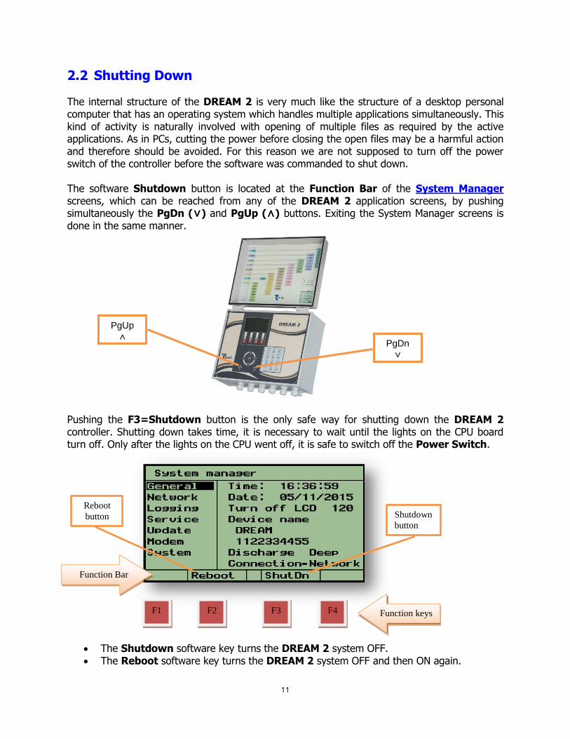
2.2 Shutting Down The internal structure of the DREAM 2 is very much like the structure of a desktop personal computer that has an operating system which handles multiple applications simultaneously. This kind of activity is naturally involved with opening of multiple files as required by the active applications. As in PCs, cutting the power before closing the open files may be a harmful action and therefore should be avoided. For this reason we are not supposed to turn off the power switch of the controller before the software was commanded to shut down. The software Shutdown button is located at the Function Bar of the System Manager screens, which can be reached from any of the DREAM 2 application screens, by pushing simultaneously the PgDn (˅) and PgUp (˄) buttons. Exiting the System Manager screens is done in the same manner.
Pushing the F3=Shutdown button is the only safe way for shutting down the DREAM 2 controller. Shutting down takes time, it is necessary to wait until the lights on the CPU board turn off. Only after the lights on the CPU went off, it is safe to switch off the Power Switch.
The Shutdown software key turns the DREAM 2 system OFF. The Reboot software key turns the DREAM 2 system OFF and then ON again.
Function Bar
F2 F3 F1 F4
Reboot
button Shutdown
button
Function keys
PgUp
˄ PgDn
˅

12
The Reboot and Shutdown functions are activated by pushing the red function keys located underneath the Function Bar of the screen. Both functions preserve all the data included in the controller except the statuses and left quantities of programs.
3. THE INTERNET COMMUNICATION The DREAM 2 has 3 options for accessing the internet:
Using a Cellular Modem supplied by Talgil and plugged into the CPU board. Using an Ethernet card for connecting to a Local Area Network. Using a USB Netstick plugged into the motherboard.
The controllers after power up will use their internet link to login to the service and stay online. On the other end there are the users that want to access the controllers, they got two options: one option is the software package called CONSOLE and the other is an internet site called SPOT. Both options enable the users to login to the SERVICE whose task is to coordinate between users and their controllers. Additionally the SERVICE contains a large DATA BASE that stores all the information about all the controllers and the ADMINISTRATION software that decides about who is permitted to access which controller. When a controller tries to login, the SERVER will ask its ID number and its full Image contents. If the Image structure is correct, the controller will be permitted to login, otherwise it will be rejected. If this is the first time for this controller to login, the SERVER will include its ID in the list of recognized controllers and will allocate for it space in the DATA BASE. Once logged in, the SERVER will keep asking the controller repeatedly “What is new?” in order to keep the DATA BASE up to date, so that users interested in some information about the controller, would be able to find it in the DATA BASE. The drawing to the right demonstrates the physical layout of the communication between users and targets (controllers) in the DREAM 2 system. The procedure of setting up the internet communication is explained below.
Selecting the mode of communication and setting the needed parameters is done at the System Manager screens.

13
3.1 Communication through Ethernet
Step 1- Enter the System Manager screens by pressing the PgDn (˅) and PgUp (˄) keys simultaneously.
Step 2- While the cursor is placed on the General subject use the right arrow to
move the cursor to the right side of the screen and then use the down arrow to move the cursor to the Connection row. Hit the Enter key to open the options selection window, select Network and hit the Enter key for confirmation.
Step 3- Use the left arrow to bring back the cursor to the left side of the screen and use the down arrow to place the cursor on the Network subject. This subject deals with defining the IP address and the Gate Way address at which the server can locate the controller.
Step 4- Use the right arrow again to move the cursor to the right side of the screen, the cursor will rest on IP address. Usually selecting the Auto mode will do the job. However in special cases when the Auto mode does not work, the Manual mode can be selected and then the IP address and the Gate Way address can be manually inserted. Usually in such cases the person in charge of the local network should be consulted.
IP address of the
controller
Gate Way
address

14
Step 5- Use the left arrow to bring back the cursor to the left side of the screen and use the down arrow to place the cursor on the Service subject. This subject deals with defining the IP address and the port of the Server through which the controller can login to the system.
Step 6- The IP address (DNS) of the Server is srv.talgil.com and the port to be used is 55300. If the IP address is incorrect and has to be changed, bring the cursor to the existing address and press the Enter key, as a result the screen will change into an editor screen like the one below, in which the characters need to be selected one by one. When the correct string is complete use F3=Apply to exit the editor screen.
Step 7- When the Dealer’s users name is not defined, the controller will be registered as belonging to Talgil, therefore in order to make it register as belonging to the Dealer’s organization, the Dealer should insert his user name before letting the controller login for the first time.
Step 8- At this stage the procedure is complete and the controller is ready for logging
into the Service, use F2=Reboot to let the controller restart.
IP address of the
Server (DNS)
The port for
entering.
The Dealer’s
user name

15
The success or failure of connection can be checked at the following screen which can be reached from the Main menu by hitting F2=About. To get back to the Main menu push the PgDn (˅) and PgUp (˄) keys simultaneously.
The connection process may take some time, however if it fails we can always try to use F4=Serv to force another connection trial, otherwise the controller will try to reconnect every few minutes.
3.2 Communication through Modem or Netstick
Step 1- Enter the System Manager screens by pressing the PgDn (˅) and PgUp (˄) keys simultaneously.
Step 2- While the cursor is placed on the General subject use the right arrow to move the cursor to the right side of the screen and then use the down arrow to move the cursor to the Connection row. Hit the Enter key to open the options selection window, select Modem and hit the Enter key for confirmation.
Step 3- Use the left arrow to bring back the cursor to the left side of the screen and use the down arrow to place the cursor on the Modem subject. This subject deals with defining the Model of the modem in use and the APN of the sim card provider to be used.
Successful
connection

16
Step 4- Use the right arrow again to move the cursor to the right side of the screen, if the model of the modem you are going to use is different from the selected one, hit the Enter key and select the correct one from the selection table that contains the list of modems recognized by the system, other modems are not supported.
Step 5- Use the down arrow to get to the APN row. The APN is the Access Point Name required by the cellular provider whose SIM card is placed in the modem. Without the correct APN the cellular carrier will not permit GSM, GPRS, 3G or 4G data transfer.
Step 6- The User name and Password fields will usually remain blank unless the cellular provider requires using them. The Dial field should remain untouched. The Status row indicates the status of the modem and the Signal field shows the signal strength at the moment of connection. The range for normal signal level will be 10 to 30.
Notice that: The function key F3=Connect can be used in order to force the modem to restart. We shall use this option whenever we are sure that all the parameters are properly defined and still the modem fails to connect.
Step 7- Continue with setting the Service parameters as explained starting from Step 5 of the previous paragraph 3.1
4. THE SYSTEM MANAGEMENT SCREENS
The System Management screens were already mentioned above however due to their importance we shall devote a special chapter to describe their contents in details. The System Management screens are usually hidden, but can be reached from any of the DREAM 2 application screens by pushing simultaneously the PgDn (˅) and PgUp (˄) buttons. Same two buttons will be used later on for getting back into the DREAM 2 application screens. While being at the System Management screens, the left side of the display contains a menu of subjects, and the right side shows the details of the selected subject. Selecting subjects is
done by moving the cursor up/down to the desired subject and then hitting the right arrow key. The cursor moves right to the first editable parameter of the selected subject.
4.1 General
The subject “General”, deals with the information below: Menu of
subjects
The cursor is
placed on the
subject -
“General”
ID number

17
The current time and date – the system shows the current time and date as existing inside the controller any moment and this is the place where the time and date setting should be done for controllers having no access to the internet. Controllers that do have access to the service will get the time and date updated automatically each time they login to the server, taking into consideration the GMT+ the time zone defined for the particular unit. The time counting by the CPU continues even when the unit is disconnected from external power, depending only on the existence of the Lithium battery on the CPU board (see above).
At the system management screens the clock is presented as a 24 hours clock, inside the DREAM 2 application it depends on the selected language, if it is English US, the clock will be in AM/PM.
The LCD turn off time – defines the delay for switching off the LCD display after detecting no activity of the keyboard.
The Device name and ID number – shows the name given to the unit by the user and
its ID number. The Device name can be changed through the CONSOLE or the ADMINISTRATION software. The ID number is unique to each CPU board and cannot be changed. It is important to point out that all the information related with the controller and stored in the Data Base, is associated with its ID number, so if for some reason the CPU has to be replaced, the Service must be notified about the replacement by activating the REPLACE command.
The Discharge level – depends on the type of backup battery used by the system. If it is
a deep discharge battery the setting should be “Deep” otherwise it should be “Normal”. At “Normal” discharge the system will report low battery when the battery voltage drops below 12v, at “Deep” discharge it will happen below 10.5v. When the system reaches the low battery level, all activities will be halted, and a low battery alarm will be generated. If the battery will keep losing another volt, the system will shut itself down.
Connection – this is the place where the type of connection to the internet is defined.
The options are:
Network- using Local Area Network (Ethernet) connection. Modem- using cellular modem or Netstick connection. None-no connection to the internet is needed.
If “Network” was selected, the subject “Modem” will become not accessible and vice versa.
4.2 Network
By selecting Network connection we declare that the communication is meant to be via a Local Area Network (LAN) or Ethernet supplied by a Router.

18
The connection between the DREAM 2 controller and the Router will be by the External CAT5 cable demonstrated below. There is an Internal Ethernet cable that goes from the Mother board to the Ethernet Interface card, this cable is supplied with the system, the other one is not. When both cables are connected properly, the 3 LEDs on the Ethernet interface card D1, D2, D3 are supposed to light with D2 blinking.
At the System manager/Network screen we are meant to define some addresses as detailed below. There are two ways for doing that, the Auto mode will automatically detect the IP, GW and DNS addresses and usually this will be the easiest way to go and there will be no need for any manual setting. In rare cases Manual setting will be required and then the person in charge of the local network should supply the following information:
The IP address – This is the address given for the DREAM 2 within the router, or in other words, this is the address at which the controller can be found on the Internet.
The GW (GateWay address) – is the IP address of the router. The DNS – it is the address of the DNS (Domain Name System) server to be used for
resolving DNS names into IP addresses. The Netmask – should be left unchanged.
The parameters will get into effect after rebooting the controller. At the Router following outgoing ports must be enabled: ports 55299-55300 (TCP) – for controllers login port 21 (TCP) – for service update port 11094 (UDP) – for open vpn ports 2001-2004 (TCP) – for maintenance and service
Manual or Auto
selection of the
address
The IP address of
the controller
The cursor
is placed
on the
subject -
“Network”
The CPU
board
Internal
Ethernet cable
External
CAT5 cable
The
Motherboard
Ethernet
interface card

19
4.3 Logging
This subject deals with parameters related with the internal logging of the activities of the operating system and the DREAM 2 application. It is meant for technical use only.
4.4 Service
In this subject we deal with the parameters required for accessing the SERVER.
The Service IP – this is the IP address of the server - “srv.talgil.com”.
The Service port – this is the port to be used by the controllers for accessing the server - “55300”.
The Dealers username – when the controller is trying to login, the server checks the
contents of this field and if it contains a username of a legal Dealer it will register the controller as belonging to this Dealer and he will be able to use it for one of his projects. If this field is left undefined, the controller will be registered as belonging to Talgil and in order for a Dealer to be able to use it, he shall have to contact Talgil and ask for the controller to be moved to his account.
The Dealer’s user
name

20
4.5 Update
This subject is used for updating the software version of the controller and for executing some operations related with the configuration of the controller.
Updating the software version – The cursor has to be placed underneath the “Update source:” row, then the new version can be loaded either through the Internet or from a USB memory stick. For selecting the update source you need to bring the cursor to the row that says “Update from…” and push F3=Change the following options will be revealed:
Update from USB – the update will be taken from the memory stick plugged into the USB socket on the mother board.
Update from NET- the update will be taken from the Server through the Internet. This obviously requires the controller to be online.
Log to USB – the log file will be saved on the USB memory stick. Update beta – the update will be taken from the Server through the
internet but instead of the actual version the beta version will be loaded. The beta version is the one which is still under development and has not yet been officially released.
Place the cursor on the desired update source and push the Enter key to start the update procedure. The stages of the update procedure will be indicated on the LCD display. The update procedure takes a couple of minutes and at the end success or failure will be declared. A few seconds later the display will show the main menu of the DREAM 2, ready for use.
The current
software version
Date of last
configuration

21
The software update from USB requires two files: gdreamSetxy.md5 and gdreamSetxy.tar where “xy” represent the version number. The system will look for those files in the folder called tlgupdate on the root directory of the memory stick.
Configuration updates – The configuration of a controller which is also known as
the image of the controller, contains all the information about the specific unit that defines its unique structure including the hydraulic network structure, the hardware used, the connections list, the constant parameters and even the programs defined by the user.
There are several operations that can be executed with the configuration. When the cursor is placed at the row containing the Date of last configuration pushing F3=Change will reveal the following options.
Set default configuration – If the image of the controller is lost or corrupted, it will be rejected by the server. In that case a default configuration can be loaded and after the connection to the server is established, the correct image can be loaded through the internet. It is important to know that the server creates a backup image file each evening and keeps the last ten of them, so when recovering is needed, it can be decided which of the backup images to use.
Backup the configuration to USB – will save the configuration file on
the USB memory stick.
The main menu of
the DREAM 2
controller
22
Restoring the configuration from USB – will restore the configuration of the controller from the backup file stored on the USB memory stick.
Recovering configuration from internal backup – Loading the
configuration from the internal backup saved inside the controllers memory each midnight.
VPN ON/OFF switch – this is the place where the Virtual Private Network can be
activated. The VPN acts like a bypass to the regular communication channel, which is used by the technicians in case of need. Activating the VPN should only be done by request from the technical team of Talgil.
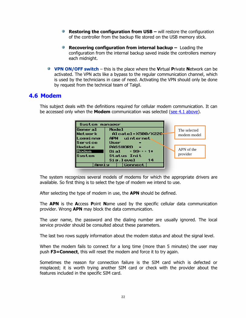
4.6 Modem
This subject deals with the definitions required for cellular modem communication. It can be accessed only when the Modem communication was selected (see 4.1 above).
The system recognizes several models of modems for which the appropriate drivers are available. So first thing is to select the type of modem we intend to use. After selecting the type of modem in use, the APN should be defined. The APN is the Access Point Name used by the specific cellular data communication provider. Wrong APN may block the data communication. The user name, the password and the dialing number are usually ignored. The local service provider should be consulted about these parameters. The last two rows supply information about the modem status and about the signal level. When the modem fails to connect for a long time (more than 5 minutes) the user may push F3=Connect, this will reset the modem and force it to try again. Sometimes the reason for connection failure is the SIM card which is defected or misplaced; it is worth trying another SIM card or check with the provider about the features included in the specific SIM card.
The selected
modem model
APN of the
provider

23
4.7 System This subject is supplying information for the use of the technical staff of Talgil.
5. THE VARIOUS I/O OPTIONS The following chapter describes the various I/O options including the various I/O interfaces, I/O boards and RTUs recognized by the DREAM system:
5.1 Interface for local I/O AC or DC
The local I/O interface may control 1 or 2 I/O boards of 16 outputs and 8 digital inputs. It is meant for reading digital inputs and activating outputs, which are close enough to be directly connected to the control unit.
Let’s have a closer look at the local I/O interface:
The jumper by which the interface is adjusted to AC or DC I/O boards
The address switch by which the interface address is set
Three indication LEDs
Test button
Local I/O
interface AC/DC Local I/O board (1)
16 outputs / 8 inputs
Local I/O board (2)
16 outputs / 8 inputs
Reset button

24
The same interface is used both for AC and DC I/O boards. The selection is done by a jumper that must be set according to the type of I/O boards used. Naturally AC I/O can only be used when constant supply of electricity is available. Each interface in the system must have a unique address by which it will be recognized when communicated by the CPU. The address switch must be set to the address selected for the particular interface during the hardware definition which is part of the configuration process. The addressing uses a binary coding as explained below:
There are 6 micro switches numbered 1,2,3,4,5,6. Each micro switch according to its ordinal number represents a value between 1 and 32 as shown above. The address is calculated by summing up the values of the micro switches that are in the ON position. Appendix "A" supplies a conversion table from binary to decimal that shows the setting of the switches required for each address.
The red LED indicates the communication between the CPU and the interface. When the communication functions properly, the red led will blink a short blink each second. The yellow and green LEDs serve the I/O test mode. After pushing the test button, the interface goes into the I/O test mode. The yellow LED tells us whether we are testing outputs or inputs. During the outputs test yellow LED will be constantly ON and then each output will be opened and closed, each opening and closing will be indicated by a blink of the green LED . During the inputs test the yellow LED will blink once per each input being tested and if a closed contact is detected, the red led will blink as well.
5.1.1 I/O expansion and Remote I/O When having a large number of local Inputs or Outputs we have to take into consideration that the Motherboard of the DREAM 2 may accommodate one interface and no more than two local I/O boards, therefore the maximum number of outputs, and inputs inside the enclosure is limited to 2x16=32 outputs and 2x8=16 digital inputs. When this is not enough, I/O expansion unit must be used. The I/O expansion unit will contain the local I/O interface, the I/O boards, a Motherboard, and a Power supply, which may be AC or DC depending on the availability of electric source. When the expansion is installed away from the controller we call it a Remote I/O unit.
1 2 3 4 5 6
ON
1 2 4 8 16 32The value represented
by each micro switch

25
The following pictures show the connection between the DREAM 2 and the I/O expansion unit. The connection is by a 2 wired cable connected between the remote I/O RS485 terminals on the two motherboards. In case the I/O expansion unit is installed far from the DREAM there will be a Bridge board added at the DREAM side and the connection will be through the Bridge which is a special board for connecting remote interfaces (explanation about the Bridge can be found at the paragraph dealing with the REBRAN board).
Beware of the polarity!! The RS485 communication line has a positive wire marked “P2” and a negative wire marked “N2”. Do not confuse between them.
A few facts about inputs, outputs and connections to the I/O boards: Digital Inputs (same on AC and DC I/O boards)
The digital inputs receive dry contact sensors with no polarity. Each input is connected to the I/O board by 2 wires that may be interchanged. Several inputs may share one wire as common; it will be connected to any of the
terminals marked by the letter “G”. Commons of different I/O boards cannot be interconnected.
Remote I/O RS485 terminal at the expansion unit
Remote I/O RS485 terminal at the DREAM 2 unit

26
The maximal length of the cable from the I/O board to the sensor should not be longer than a few meters.
AC Outputs
AC outputs are activated by 24V AC. Each AC output is connected to the I/O board by 2 wires that may be interchanged. Several AC outputs may share one wire as common; this wire will be connected to any
of the terminals on the outputs terminal block marked by the letter “C”. The thickness of the common wire is dictated by the number of solenoids to be activated simultaneously and the power rating of the solenoids.
Commons of separate I/O boards cannot be interconnected. The length of the wires from the I/O board to the AC device to be activated may be
hundreds of meters long, but the required wire thickness grows with the distance. An output remains activated as long as it is energized. Solenoids of normally open valves and normally closed valves will be wired the same
way to the terminal board but will differ in the connection of the command tubes and sometimes will differ in their physical structure.
Measuring the voltage of an AC output while it has no load connected to it, can be misleading, it will show 24v AC even when the output is not activated.
DC Pulse Latching Outputs
DC latching outputs are activated by short pulses of energy and they are kept in their last position by magnetic means, that’s why they are energy saving.
Each DC output is connected to the I/O board by 2 wires – red and black of which the polarity is important. The terminal block of the outputs contains two terminals per each output; one terminal is marked by the ordinal number of the particular output and the other by the letter “C”. For normally open valves, the black wire will be connected to the terminal marked “C” and the red wire to the terminal marked by the ordinal number. For
The outputs’ common is marked by “C”
Inputs terminal block
Outputs terminal blocks
Inputs terminal block
Outputs terminal block
The outputs’ common is marked by “C”
The inputs’ common is marked by “G”
The inputs’ common is marked by “G”

27
normally closed valves, the position of the black and the red wires should be interchanged.
Several DC outputs may share one wire as common, this wire will be connected to any of the terminals on the outputs terminal block marked by the letter “C” which serves as the outputs common.
Commons of separate I/O boards cannot be interconnected. The length of the wires from the I/O board to the DC latching device to be activated,
cannot be long, it differs with the type of solenoid used. The correct distance should be consulted with the manufacturer.
An output remains activated as long as it does not receive the opposite command. The voltage at the DC output cannot be measured by regular voltmeters because it
exists for a very short period.
5.2 Interface for single cable 2 wired RTUs
When it is required to reach distant I/O devices (radius of 10 km) and it is possible to lay a 2 wired cable in the field, we shall use the 2 wired RTU system to reach all the remote I/O devices. The RTUs are Remote Terminal Units, which can read digital or analog inputs and activate DC latching outputs. The RTUs will be placed wherever there are I/O devices to control. A 2 wired cable will be running from the 2W interface to the RTUs like branches of a tree. The 2 wired line is used both for communication and for supplying energy to the RTUs from the 2W interface. Up to 60 RTUs may be connected to a 2W interface. The DREAM 2 may handle several 2W interfaces.

28
DREAM
Layer 0
Layer 1
RTU
1
RTU
7
RTU
5
RTU
3
RTU
9
RTU
2
1
2
9
7
5
3REPEATER
Detailed information about the 2W RTU system can be found in the manual “DREAM 2W RTU SYSTEM 2007”.
5.3 Interface for radio communicated RTUs
When remote I/O devices cannot be reached by cable, radio communicated RTUs will be used. The RF INTERFACE will communicate with the RF RTUs through an RF MASTER receiver/ transmitter located on top of a high pole next to the RF INTERFACE. In the field, the RTUs will be placed next to the I/O devices to be controlled. Each RF RTU consists of an RTU BASE to which the inputs and outputs are tied, and an RF SLAVE receiver/ transmitter which will also be installed on top of a high pole. The SLAVES exchange information with the MASTER, each in its appropriate timeslot, dictated by the RTU’s address. It is expected that there will be a clear line of sight between the antenna of the RF MASTER and the antennas of the RF SLAVES otherwise some RF RTUs can be turned into REPEATERs for the benefit of their neighbors. Similar to the 2 wired RTUs, the RF RTUs can read digital and analog inputs and activate DC latching outputs and here again there can be several channels of RF RTUs with up to 60 RTUs per channel. Detailed information about the RF RTU system can be found in the manual “DREAM RF RTU GENERATION III IV and IV.V”.
5.4 Interfaces for local analog inputs
As mentioned above, analog inputs can be read both through the 2W RTU system and the RF RTU system, however analog sensors located in the close vicinity of the DREAM 2 controller can
Master
Slave
29
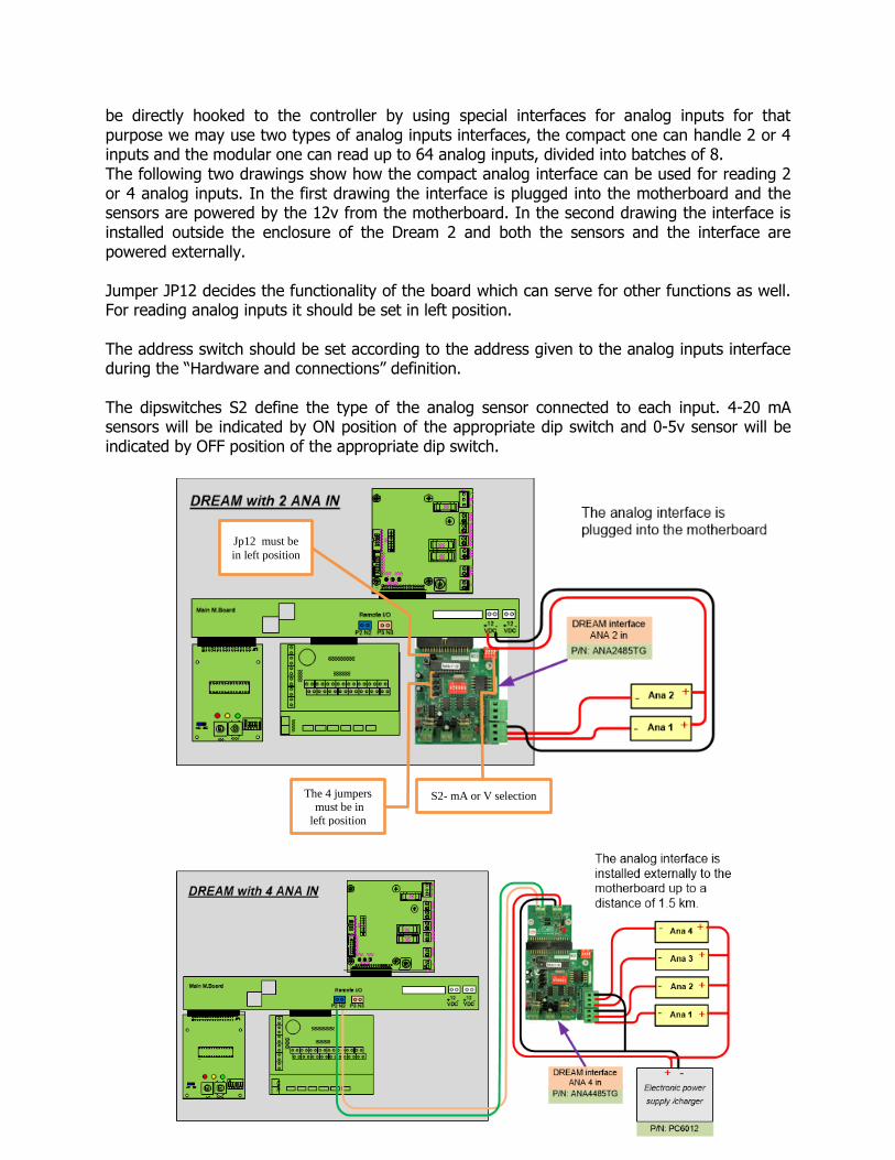
be directly hooked to the controller by using special interfaces for analog inputs for that purpose we may use two types of analog inputs interfaces, the compact one can handle 2 or 4 inputs and the modular one can read up to 64 analog inputs, divided into batches of 8. The following two drawings show how the compact analog interface can be used for reading 2 or 4 analog inputs. In the first drawing the interface is plugged into the motherboard and the sensors are powered by the 12v from the motherboard. In the second drawing the interface is installed outside the enclosure of the Dream 2 and both the sensors and the interface are powered externally. Jumper JP12 decides the functionality of the board which can serve for other functions as well. For reading analog inputs it should be set in left position. The address switch should be set according to the address given to the analog inputs interface during the “Hardware and connections” definition. The dipswitches S2 define the type of the analog sensor connected to each input. 4-20 mA sensors will be indicated by ON position of the appropriate dip switch and 0-5v sensor will be indicated by OFF position of the appropriate dip switch.
Jp12 must be
in left position
S2- mA or V selection The 4 jumpers
must be in
left position

30
The way to connect the modular analog interface that can read up to 64 analog sensors is described by the following drawing. The interface utilizes special RTUs that can read 8 analog sensors each. Here again the interface can be plugged into the mother board or installed externally.
5.5 Interface pH/EC (Fertmaster)
When the system is required to measure/control the pH (acidity) and the EC (Electro Conductivity) of the water, a special interface will be used. Apart from reading the analog values of the pH and EC electrodes, the pH/EC interface is capable of handling 6 injectors of fertilizers and a booster pump; it is equipped with a display and a key board which enable calibrations, parameters setting and monitoring to be done directly at the interface. During the injection process, it receives from the DREAM 2 controller all the details and the requirements of the particular process and it executes the injection accordingly. All along the injection process, the DREAM 2 is updated continuously about the status and the results.
pH/EC interface FERTMASTER
31
Detailed information about the pH/EC Interface can be found in the manual “FERTMASTER pH/EC USER GUIDE 2007”.
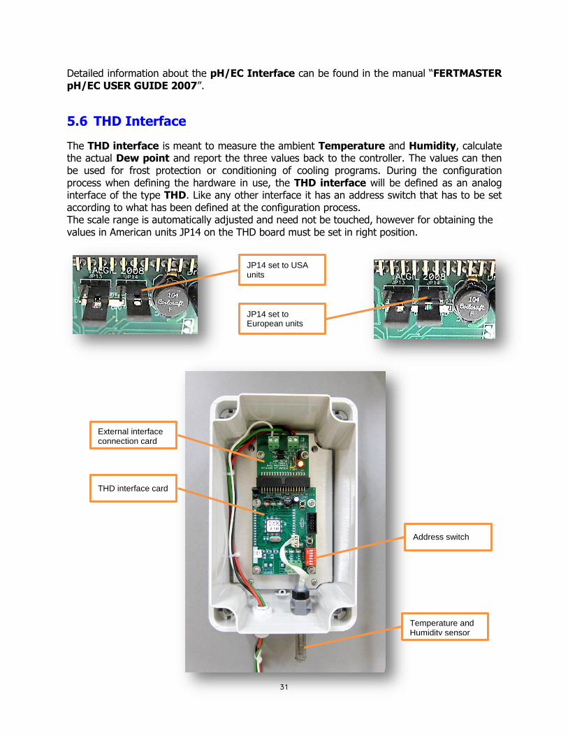
5.6 THD Interface
The THD interface is meant to measure the ambient Temperature and Humidity, calculate the actual Dew point and report the three values back to the controller. The values can then be used for frost protection or conditioning of cooling programs. During the configuration process when defining the hardware in use, the THD interface will be defined as an analog interface of the type THD. Like any other interface it has an address switch that has to be set according to what has been defined at the configuration process. The scale range is automatically adjusted and need not be touched, however for obtaining the values in American units JP14 on the THD board must be set in right position.
External interface connection card
THD interface card
Temperature and Humidity sensor
Address switch
JP14 set to USA units
JP14 set to European units

32
5.7 Weather station Interface
The Weather station interface enables connection of a “Davis - Vantage pro2” weather station to the system. The weather station supplies the controller the following data:
1. Barometric pressure 2. Ambient temperature 3. Humidity 4. Wind speed 5. Wind direction 6. Solar radiation 7. Daily rain 8. Rain rate 9. UV radiation 10. Evapotranspiration 11. Dew point
The information is transferred by communication through the RS 485 line. The Weather station is defined during the configuration process when defining the hardware in use. The Weather station interface will be defined as an analog interface of the type DAVIS. Like any other interface it has an address switch that has to be set according to the definition made at the configuration process. The eleven sensors will be automatically defined along with the weather station; they need not be defined separately. The scale range of the sensors of the weather station is automatically adjusted and need not be touched.

33
Detailed information about the Weather station can be found in the manual “DREAM with Weather station”.
6. LIGHTNING PROTECTION
A lightning will usually penetrate the system through the long cables connected to it; therefore all the long cables must be protected against lightning. In the DREAM 2 there can be several cases where long cables will require lightning protection: The DREAM++2W - the 2 wired line, can be kilometers long, the RS485 communication line between the DREAM and remote interfaces can sometimes be very long and the DREAM AC may also have long wires between the AC I/O boards and the solenoids. The lightning protection is accomplished by adding special protection units between the cables coming from the field and the device to be protected. The lightning protection circuits contain components that react very fast when hit by a lightning. These components turn into a short-circuit that leads the lightning energy into the ground. For this to happen, each lightning protection unit must have a very good connection to the ground. In the 2W systems each RTU has a built in lightning protection therefore it is very important not to forget the connection to the ground of each RTU. The connection to the ground is done by a thick wire connected to a metal rod inserted deeply into the ground. The following pictures show the three types of lightning protection units- one that is used for the 2W single cable system, the second that is used for protecting the RS485 communication line, and the last one is for protecting the wiring that goes from the I/O AC board to the 16 AC solenoids connected to it.
Weather station’s console
Sensor’s suit
Power supply
Lightning protection
Weather station interface
RS485/RS232
External interface connection card

34
6.1 Lightning protection for the 2W single cable system
Ground
6.2 Lightning protection for RS485 communication line
Ground
6.3 Lightning protection for 16 AC outputs
Ground
Cable coming from the field
Cable going to the 2W interface
Cable
com
ing
from
the f
ield
Cable
goin
g to
th
e 2
W in
terfa
ce
Cables coming from the field
Cables going to I/O AC board

35
Notice that all the three lightning protection boards have one side marked “Field” or “Line”, this is the side where the cable coming from the field should be connected. The other side, which is marked “Device” is the side where the protected device will be connected.
Notice also that the RS485 protection board has at both sides of its terminals one terminal, which is marked by a white spot and the other which is not. This is done in order to be able not to confuse between the “P” (positive) and “N” (negative) wires of the RS485, if the “P” was connected to the white spot terminal on one side the continuation of the “P” at the other side should also be connected to the white spot.
Although lightning protection units can do a very good job protecting the system from being severely damaged by lightning, it must be understood that we cannot expect a 100 percent protection in any case. There is no protection against a direct hit; the energy of the lightning is too high to be absorbed by any protection system.
6.4 The enclosures of the DREAM system
The DREAM 2 controllers can be ordered in one of the two enclosure formats:
PLASTIC ENCLOSURE METAL CABINET The metal cabinet is meant for wall mounting, it has a bigger size and therefore it may accommodate additional interfaces, expansion boards, lightning protection boards which otherwise would be located in additional boxes. The plastic enclosure can be wall mounted or installed on a metal pole. Any additional equipment that cannot be installed inside the enclosure will be installed externally in separate boxes.
7. INSTALLATION STEPS Setting up a DREAM control system consists of the following steps:
Mounting the controller and its peripherals. Defining the system’s configuration. Connecting the input/ output devices to the controller and to the RTUs based on the
connections list resulting from the configuration process.
Testing the operation of all the inputs/ outputs.
36
Defining the constant parameters. Setting up and testing the internet communication. Teaching the user how to use the system.
Any connection or disconnection of components to the system must be done only while the power switch is turned OFF, otherwise unpredictable damage might be caused. However remember to shut down the software before turning off the power switch.
7.1 Mounting the controller The best location for mounting the DREAM will be on a wall, under a roof protected from direct sunlight and rain. Therefore, people will usually place the DREAM in their office or in the pump house or just in a toolshed. Usually at those places, there will be electric power available and therefore there will be no question about how to energize the system. However, the DREAM can also be installed outdoors attached to a metal pole by “U” clamps and powered by solar panel. If the DREAM is DC type which means that it activates DC latching solenoids that cannot be installed far from the commanding unit, therefore all the solenoids commanded by the DREAM will be installed close to the controller and between the valves and the solenoids the connection will be by command tubes. The same is true about connection of solenoids to remote I/O DC expansion units and all kinds of RTUs, all of them activate DC latching solenoids which cannot be installed away from the commanding unit. If the DREAM contains local I/O AC outputs, obviously all the cables arriving from the solenoids will have to reach the local I/O terminal boards of the DREAM. The same is true about connection of solenoids to remote I/O AC expansion units. Now, the question that needs to be answered is: where exactly should the various outputs and inputs be connected to the various terminal boards? The answer is that the order of connection is not dictated by the system, but by the installer. Inside the DREAM there is a connections table that defines the connection point for each of the declared devices. So a convenient way of working will start with defining the configuration of the system in which all the devices are introduced, then defining the type of hardware constructing the system and then defining the connections table. The printout of the connections table can then be used when executing the connections in the field. The following chapter describes the configuration process that includes the steps described above.

37
7.2 Defining the configuration
There are several ways to define the configuration of a controller. The easiest will be by using the Image maker included in the Console /Tools. The way to use the image maker is explained at the “DREAM 2 CONSOLE GUIDE”. In the following chapter we describe the configuration process when executed directly from the DREAM’S control panel or by using the DREAM simulation software that simulates the DREAM controller on the PC. When done by the simulation software, the resulting configuration file can be loaded into the DREAM 2 controller through the USB socket as explained above in paragraph 4.5 or through the internet by executing the “Upload image file” command that can be found either at the Console/Tools/Target_tools or at the Admin/Targets/<selected_target>/Actions.
For starting the configuration process, select Setup in the main menu, then in the submenu select SYSTEM CONFIGURATION. The selection is done by the ENTER key.
Entering into the SYSTEM CONFIGURATION subject without inserting a password enables only to watch the existing configuration. In order to get permission for defining a new configuration, a password is required. The password is 139, it is not a secret password, it is only meant to make the user think again before erasing the previous definition and all the accumulated information.
The configuration process is executed in three steps:
Network definition – includes the definition of the hydraulic network structure the devices to be controlled and the relation between them.
Hardware definition – defines the kind of hardware used in the system for controlling the devices defined during the network definition.
Connections definition – defines the connections table that contains the lists of all the physical connection points of the devices defined. When the system contains only local I/O and does not make use of any RTUs, it is very convenient to use the option of AUTOMATIC ALLOCATION that makes the connections allocation automatically, allocating the inputs/ outputs in a sequential manner.

38
At the end of the last step the physical connection of all the devices is well known, therefore the wiring process may be started. The following page contains an example network, which will be used for demonstrating the configuration process. The example demonstrates a system with two water sources "A" and "B" and 8 irrigation lines marked L1 – L8. Lines L1 to L6 are irrigating field crops, line L7 is a nursery, and L8 irrigates a palm plantation. The DREAM 2 control unit will be located at the pump house at source "A" where electricity is available. The accessories that are in close proximity with the DREAM 2, will be wired directly to the local I/O terminal boards at the DREAM 2 itself. The accessories of lines L1 to L6 and the second water source are connected by use of 17 single cable RTUs. The connection of the plantation L8 is done by 2 radio RTUs, and the nursery L7 which contains a large number of valves close to each other, will be connected by a remote I/O expansion unit.

39
b
b
f1
DP
f2 f3 f4
Central
fertilizer
site
Central
filter site
Water
source "A" Water
source "B"
L3
L2
L4
L5L6
Free
water
meterSatllite
C1
C2
RTU
3
RTU
4
RTU
5
RTU
6
RTU
7
RTU
8
RTU
9
RTU
10
RTU
11
RTU
12
RTU
14
RTU
15
RTU
16
Dream
L1
RTU
1
RTU
2
Nursery
RTU
13
Remote
I/O
L7
RTU
RADIO
1
RTU
RADIO
2
RTU
17
Plantation
L8
P
S1S2
Local Fert
site of line 5
Contact
of level
sensor
Source
water meter
Local Fert
site of line 6
Main valve
of line 2

40
7.2.1 The network definition
The network definition process consists of a series of screens through which the contents and the structure of the network is defined. The screens are arranged in a vertical order. Use the PAGE DOWN () and PAGE UP () keys to move between the screens.
We start by declaring the quantities of the main items comprising the hydraulic network:
The satellite outputs are very useful tools; they can be utilized in 3 ways:
1. A satellite can be attached to any output of the system in order to have it working together with those outputs. It will be active as long as any of the other outputs is active.
2. A satellite can be activated by a condition becoming true and stay activated as long as the condition is true.
3. Conditions can be defined on the statuses of satellites, so if we combine this feature with feature number 1 above, we can actually get conditions depending on the statuses of any of the outputs that the satellite are attached to.
Detailed explanation about how can the satellites be utilized, is supplied in the user guide.
There are 2 water sources ("A" and "B") There are 8 irrigation lines (L1-L8)
There is 1 central fert site serving (L1-L4,L7,L8) " There is 1 central filter site serving (L1-L4,L7,L8) " The satellite outputs are intended to work in conjunction with other outputs. In our case there are two valves defined as satellites" S1 and S2

41
When the system contains water sources each water source will have a definition of the number of outputs (usually water pumps) belonging to the water source and whether or not a water meter is included in the water source.
The next step will be the definition of the irrigation lines contents including the following information:
How many valves are included in each line? Does the irrigation line contain local fertilizer site? Is the irrigation line connected to a central fertilizer site, if yes to which one? Does the irrigation line contain local filter site? Is the irrigation line connected to a central filter site, if yes to which one? Does the irrigation line contain a dry contact pressure sensor? If yes, it should be the
normally open type.
Water meters that not associated with irrigation lines
Source A has 2 pumps and source B has 1 pump
The irrigation lines will automatically get the default structure as defined here. Later on each line can be adjusted as required.
Source A has no water meter but source B does
In our example there are two contacts C1 and C2 used as level sensors of source “A”
Analog inputs supply a whole range of values presented as 4-20 mA or 0-5 v. Not implemented in our example
When Fert. agitation is defined there will be an additional output added to each fertilizer
injector for agitating the fertilizers.
When flow switches are added per valve they will indicate whether the valve really executed the Open/Close commands.

42
In the next step we define the connection between irrigation lines, water meters, main valves and water sources. Irrigation lines having a water meter will be indicated by “+” in the “W. meter” column. Main valves are numerated 1,2,3 … etc. If several irrigation lines share the same main valve, the number of the main valve in the “Main vlv” column will be the same. Notice that when each irrigation line has a main valve of it's own, you can use the automatic numeration button, otherwise you will have to do the numeration yourself. The selected water source in the “Source” column will be used as default during definition of irrigation programs.
Lines 1 to 4 are using central fertilizer site No. 1
Line 8 has got a pressure sensors
Lines 1 to 4 are using central filter site No 1
Lines 5 and 6 have local fertilizer sites
The number of valves of line 1 is 6
The default source of lines 1-4 ,6 is "A", and of line 5 is "B"
The numeration of the main valves
This window opens when the "Change" button is pushed enabling selection of water sources
All the lines from 1 to 6 have got a water meter
Lines 7 and 8 got no water meter
Lines 7 and 8 got no main valve
The default source of lines 7 and 8 is "A",

43
Next step is the definition of the fertilizer sites. For each site, the number of injectors has to be defined
and for each injector the existence of fertilizer meter and the existence of connection to a booster pump need to be defined.
The next step will be the definition of the filters sites
At this stage we are finished with the network definition, pushing PAGE DOWN (), brings us back to the top screen of NETWORK DEFINITION from where we can continue to the HARDWARE DEFINITION by using the rightmost red function key, or pass again through the NETWORK DEFINITION by using the PAGE DOWN key.
Central fert site No 1 and the local fert sites of line 5 and line 6 contain 2 injectors, each injector is equipped with fert meter and uses no booster pump.
There is one filter site - Central No 1 There is a
pressure differential sensor
In this case, there is no Down Stream Valve used. Generally these valves are used for increasing pressure while flushing.
The central filter site
has 4 stations

44
7.2.2 The hardware definition
The hardware definition starts with specifying the types and the quantities of I/O interfaces utilized by the specific system. The following list contains the various options of I/O interfaces. We need to specify which types of interfaces and how many of each type will be used in our system.
After defining which types of interfaces and how many of each will be utilized, we need to define the addresses of the interfaces and some of them need some complimentary information to be defined. Use the PAGE DOWN () key to reach the following table:
In our example there are 2 DC I/O interfaces, one inside the DREAM and the
other inside the remote I/O at the nursery
There is 1 two wired RTU interface serving
the communication with RTUs 1 to 17
There is 1 Radio RTU interface serving the
communication with Radio RTUs 1 and 2
Interface DC No1 (resides inside the DREAM 2
enclosure), has 1 I/O board 16/8 (16 outputs, 8 inputs)
Interface DC No2 (resides in the REMOTE I/O unit), has 2 I/O boards of 16/8 (32 outputs, 16 inputs)
Interface No3 is the 2 wired RTU interface
Interface No4 is the radio RTU interface. The scanning
rate is set to 10.0 seconds.
45
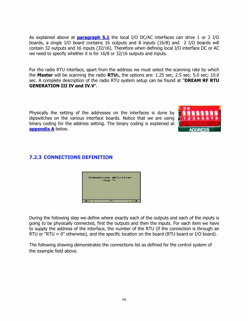
As explained above at paragraph 5.1 the local I/O DC/AC interfaces can drive 1 or 2 I/O boards, a single I/O board contains 16 outputs and 8 inputs (16/8) and 2 I/O boards will contain 32 outputs and 16 inputs (32/16). Therefore when defining local I/O interface DC or AC we need to specify whether it is for 16/8 or 32/16 outputs and inputs. For the radio RTU interface, apart from the address we must select the scanning rate by which the Master will be scanning the radio RTUs, the options are: 1.25 sec; 2.5 sec; 5.0 sec; 10.0 sec. A complete description of the radio RTU system setup can be found at "DREAM RF RTU GENERATION III IV and IV.V". Physically the setting of the addresses on the interfaces is done by dipswitches on the various interface boards. Notice that we are using binary coding for the address setting. The binary coding is explained at appendix A below.
7.2.3 CONNECTIONS DEFINITION
7.2.3.1
During the following step we define where exactly each of the outputs and each of the inputs is going to be physically connected, first the outputs and then the inputs. For each item we have to supply the address of the interface, the number of the RTU (if the connection is through an RTU or “RTU = 0” otherwise), and the specific location on the board (RTU board or I/O board). The following drawing demonstrates the connections list as defined for the control system of
the example field above.

46
Onboard
location
RTU
number
Interface
address
Valve 1 of line 8 by radio interface 4 RTU 1 output 1
Filter 4 by interface 1 output 8
Valve 6 of line 6 by
interface 3 (2 wired), RTU 16, output 2.
Valve 1 of line 7 by interface 2 (REMOTE I/O), output 1, without RTU.

47
When finished defining the connections of the outputs we continue with the connections of the
digital inputs.
When the system includes analog sensors as well, the connections list of the analog sensors will
follow the list of the digital inputs.
Analog sensors definition deserves a special attention since some kind of analog sensors are
treated differently than others. The analog sensors that are treated specially by the system are
those that are part of a group of sensors serving a special purpose. For example the analog
sensors included in a weather station, the sensors included in a THD interface and the sensors
connected to a pH/EC interface will not be defined individually sensor by sensor, but they get
defined automatically once the interface of those sensors is defined.
In the other cases the user needs to define the connection of each analog sensor the same way
the digital inputs and outputs connection is defined. However when the analog sensors are
connected through the single cable 2 wired RTU system the rules of addressing are tricky.
Details can be found in the manual “DREAM 2W RTU SYSTEM 2007”.
By use of the CONSOLE software the connections table of outputs and inputs can be exported
to excel and printed. A printed copy of the connections table can become very handy during the
connections process.
The water meter of
source B by interface 3 (2 wired) RTU 17 input 1
Fert meter 1 of Central site
1 by interface 1 (Local I/O) input 3, no RTU.
The pressure sensor of line 8 by interface 4 (radio) RTU 1 input 1.

48
F2
7.3 Testing operation of inputs and outputs Let us assume that all the outputs and inputs were properly connected according to the
connections table described above. However before all the outputs and all the inputs were
tested one by one we cannot be sure that they are all functioning as expected.
In this document we explain how to carry out the testing through the local MMI of the
controller.
7.3.1 Testing the outputs
For testing the outputs, we use the "MANUAL OPERATION" mode that can be activated from
the screen STATUS OF OUTPUTS. In the main menu select
STATUS and then in the submenu select OUTPUTS. The screen
that we arrive to contains a structured description of the outputs
included in the system. In case of large systems there may be
several screens needed to contain the complete list of outputs
the movements from one screen to another is accomplished by
use of the PgDn (˅) and PgUp (˄) buttons.
Push the red function key underneath the word "Manual", the cursor changes its form
into a blinking underline "_", now by using the horizontal arrows , the cursor can be moved
to the right and to the left, enabling selection of outputs from the list. For activating/
deactivating the selected output we use the same function key F2 which now functions as
"ON/OFF" button. The activated outputs will be marked by the symbol “^”. Make sure that
each output really follows the open and close commands as expected. To exit the manual
operation mode the ENTER key is used.
7.3.2 Testing the inputs In the main menu select STATUS and then in the submenu select IUPUTS. The screen that we
arrive to contains a structured description of the inputs included in the system. In case of large
systems there may be several screens needed to contain the complete list of inputs, the
movements from one screen to another is accomplished by use of the PgDn (˅) and PgUp
(˄) buttons.
In the STATUS OF INPUTS screen each digital input that senses a closed contact will be indicated by a “+” sign otherwise it will be indicated by a “-“.

49
7.3.3 What comes next? The installation procedure will not be considered done until some important definitions are
made.
There is the DEALERS DEFINITIONS that should be visited in order to do some "fine tuning"
of the system to make it best suited to the actual application needs. The DEALERS
DEFINITIONS contain many parameters that will cause some features to be enabled and
others to be disabled, some parameters deal with default values that need to be used in the
particular system and other parameters dictate the memory allocation for certain purposes. The
DEALERS DEFINITIONS can only be executed while there are no irrigation programs
running. For entering the procedure of setting the parameters the system requires inserting the
code “247”.
Another important thing to do is the setting of the CONSTANTS. The list of constants includes
parameters without which the configuration process is not complete and the controller will not
be able to function properly. For example, water meters and fertilizer meters need to have their
ratio defined; irrigation valves need to have their nominal flow and filling time defined.
Both of the two subjects are covered in details in the “DREAM 2 USER GUIDE 2016”.

50
8. THE DREAM SIMULATION SOFTWARE
The DREAM SIMULATION SOFTWARE is a program that enables simulating the DREAM on
the PC. The simulation software is a very useful tool for demonstrating, training, experimenting
and checking problems. The simulation software will login into the SERVER and then it
becomes accessible through the CONSOLE or the SPOT. It can be programmed exactly as a
real controller. The simulated controller has an ID number of 4 digits, this makes it different
from a real controller whose ID is of 10 digits. In order for a user to be able to access the
simulated controller by the CONSOLE or the SPOT a DEMO PROJECT has to be defined in
the ADMINISTRATION software and both the user and the simulated controller need to be
assigned to the project.
The key board of the simulation is used the same way as the key board of the real DREAM
controller except for the way the SYSTEM MANAGER screens are reached. At the real
controller we need to press simultaneously the PgDn (˅) and PgUp (˄) buttons, at the
simulation we need to activate special software “SysManager.exe” included in the software
package of the simulator.
For selecting the desired configuration file, use the File/Open option at the menu bar. The
simulation software will take over the image of the controller from which the configuration was
taken. The user may now experiment with the simulation exactly as if he was doing it on the
controller itself. The only difference is that the simulator is not connected to all the valves and

51
meters in the field and when a valve is commanded to open there will be no flow of water or
fertilizer. However at the simulation, we can get a similar effect if we activate
Configuration/Flow-simulation at the menu bar. The software will simulate the flow of water
meters according to the specified nominal flow of the valves opened under each water meter.
Free water meters will therefore not get flow simulation because they got no valves belonging
to them.
The DREAM simulation may also be used for defining a new configuration that can be saved in
a configuration file that can later be loaded into the DREAM controller.
9. SUPPLEMENTARY DEVICES
In this chapter we shall describe some devices that are used in the DREAM 2 system in special cases.
9.1 Switching electric pumps
Naturally, the switching of electric devices differs from the opening and closing of hydraulic
valves, the switching process is involved with connecting/disconnecting high power electric
sources to high power loads, this action may sometimes create sparks and electric
interferences, therefore it is better to have a good galvanic isolation between the commanding
unit and the high power electric devices being switched. This is the reason why we are using
special PUMP- SWITCHING UNITS that contain a solid state relay in which the connection
between the input and the output is optical, therefore they supply good galvanic isolation.
We are using several types of PUMP-SWITCHING UNITS that differ by the type of command
they are ready to accept and the type of load they can switch.
SWITCHING
UNIT TYPE
TYPE OF
COMMAND
TYPE OF
LOAD
REMARKS
AC/AC 24v AC Single phase
240v AC 25A
1. May require a capacitor of 1µF 400v
in parallel with the load when the
load refuses to turn OFF.
DC/AC 12v DC latch Single phase
240v AC 25A
1. May require a capacitor of 1µF 400v
in parallel with the load when the
load refuses to turn OFF.
2. Requires supply of 12v DC
DC/DC 12v DC latch 200v DC 1. Requires supply of 12v DC

52
The switching units with command of 12v DC latching can be commanded either by three wired
command or two wired command.
All types of switching units act like a relay that when activated they let the power through and
when deactivated they cut off the power from the load. In any case, the power to be switched
comes from external source and not generated internally by the unit.
When the load is a 3- phase load or it is too big, then the pump-switching unit will not switch
the power to the pump directly, but rather activate a contactor that will switch the pump ON
and OFF.
IMPORTANT: 1. In each package of PUMP SWITCHING UNIT a capacitor of 1 µF 400v is supplied. this capacitor
should be installed in parallel with the load, otherwise in some cases the pump will not turn OFF.
2. The internal contact of the solid state relay cannot be tested by Ohm-meter.
The 12v DC
power to be
connected here
The command
from controller
arrives here
The power to
be switched
enters here
The power to
the load exits
from here
No need for 12v DC power

53

54

55
IMPORTANT: It is important to point out that unlike the AC type pump-switching units, the DC type units require a power supply of 12v DC without which they would not function. When the pump-switching unit is commanded by the local I/O of the DREAM or the remote I/O expansion unit, the 12v can be taken from the power supply of the DREAM or of the expansion unit. However when the DC pump-switching unit is activated through an RTU (either 2W or RF), the 12v powering cannot be taken from the RTU resources but must be externally supplied. If solar powering is required by a 2.5W solar panel and a rechargeable battery of 3Ah.
9.2 The three functions of the REBRAN board
The following paragraph describes a special board that can be used in three different ways depending on the setting of the jumpers onboard. We call it the REBRAN board, the name is derived from the three functions the board can fulfil: RE = stands for REPEATER; BR = stands for BRIDGE; AN = ANALOG INPUTS INTERFACE
9.2.1 RS485 Repeater with optic isolation
When serving as a REPEATER the REBRAN board is meant to sit on the RS485 communication line and isolate one side of the line from the other. The input side and the output side of the board are connected onboard through opto-couplers that make the two sides
JP12 set for
REPEATER
RS485
input side RS485 output side
Baud rate selection JP7,9,10,11
define the
powering
side
12v DC feeding
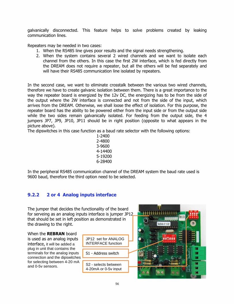
56
galvanically disconnected. This feature helps to solve problems created by leaking communication lines. Repeaters may be needed in two cases:
1. When the RS485 line gives poor results and the signal needs strengthening. 2. When the system contains several 2 wired channels and we want to isolate each
channel from the others. In this case the first 2W interface, which is fed directly from the DREAM does not require a repeater, but all the others will be fed separately and will have their RS485 communication line isolated by repeaters.
In the second case, we want to eliminate crosstalk between the various two wired channels, therefore we have to create galvanic isolation between them. There is a great importance to the way the repeater board is energized by the 12v DC, the energizing has to be from the side of the output where the 2W interface is connected and not from the side of the input, which arrives from the DREAM. Otherwise, we shall loose the effect of isolation. For this purpose, the repeater board has the ability to be powered either from the input side or from the output side while the two sides remain galvanically isolated. For feeding from the output side, the 4 jumpers JP7, JP9, JP10, JP11 should be in right position (opposite to what appears in the picture above). The dipswitches in this case function as a baud rate selector with the following options:
1-2400 2-4800 3-9600 4-14400 5-19200 6-28400
In the peripheral RS485 communication channel of the DREAM system the baud rate used is 9600 baud, therefore the third option need to be selected.
9.2.2 2 or 4 Analog inputs interface
The jumper that decides the functionality of the board for serveing as an analog inputs interface is jumper JP12 that should be set in left position as demonstrated in the drawing to the right.
When the REBRAN board is used as an analog inputs interface, it will be added a plug in unit that contains the terminals for the analog inputs connection and the dipswitches for selecting between 4-20 mA and 0-5v sensors.
Input side RS485
JP12 set for ANALOG INTERFACE function
S1 - Address switch
S2 - selects between 4-20mA or 0-5v input

57
The board can be plugged into the motherboard directly or connected remotely through the remote I/O RS485 channel. When installed remotely the board requires 12v DC for energizing and 2 wires for the RS485 communication. The board enables reading up to 4 analog inputs of 4-20 mA or 0-5v. Each DIP switch of S2 when set in upper position indicates 4-20 mA input.
The address switch should be set according to the address given to the analog inputs interface during the configuration process. The setting of the other jumpers onboard should be left unchanged. Additional information about the way to connect the 4 analog inputs interface can be found at the paragraph that deals with Interfaces for local analog inputs above.
9.2.3 RS485 Bridge
The third function of the REBRAN board is to serve as a BRIDGE on the RS485 communication line between the DREAM and remote interfaces. The bridge improves the communication with the remote interfaces connected to it. On one side the bridge is plugged into the DREAM’S motherboard and on the other side it is connected to the remote interfaces by cable of 2 wires. The address setting of the BRIDGE must be done in a careful way. It is important to set the address switch of the BRIDGE to an address that is higher than the addresses of the interfaces NOT passing through the BRIDGE and the address of any remote interfaces working through the bridge must be equal or higher to the address of the BRIDGE itself.
9.3 The pulses divider
The purpose of the PULSES DIVIDER unit is to enable reading short or high rate pulses by controllers having a scanning rate of once in a second or lower. The PULSES DIVIDER expects to receive dry contact Inputs usually arriving from devices such as water meters or fertilizer meters, it will count the pulses and emit an output pulse per each
JP12 set for BRIDGE function
The remote terminals will be connected here

58
4 pulses
1 pulse
INPUT
OUTPUT
Pulse 1 Pulse 2 Pulse 3 Pulse 4
Positive part
Negative part
"x" input pulses counted. The number “x” is based on the selected setting. A special case is when “x” equals 1, then for each pulse received at the input there will be one pulse generated as output. The width of the positive and negative parts of the pulse will be no less than 1 second. This way even if the input pulse was narrow the output pulse will be wide enough not to be missed by the controller. Obviously, the pulse rate in this case cannot be higher than one pulse per every 2 seconds. In the OPERATION TABLES below the Division factor defines how many input pulses will be represented by each output pulse. Notice that a complete pulse consists of the positive and the negative parts of the pulse.
EXAMPLE: Let’s assume that Dip switch 5 = OFF (TABLE 1 is selected) and the Dip switches 1-4 are set to: 0100 (division by 4). In this case each 4 pulses at the input will cause 1 symmetric pulse to be emitted at the output. Notice that a complete pulse consists of both the positive and the negative parts.
OPERATION TABLE 1 (Dip switch 5 = OFF)
Dip Switches 1-5
Division factor
00000 1
10000 2
01000 4
11000 6
00100 8
10100 10
01100 12
11100 14
00010 16
10010 18
01010 20
11010 22
00110 24
10110 26
01110 28
11110 30
OPERATION TABLE 2 (Dip switch 5 = ON)
Dip Switches 1-5
Division factor
00001 40
10001 60
01001 80
11001 100
00101 120
10101 140
01101 160
11101 180
00011 200
10011 400
01011 600
11011 800
00111 1000
10111 1200
01111 1400
11111 1600

59
9.3.1 The Push Buttons There are 3 push buttons with the following functions: Reset button- restarts software. Indicator button-changes the function of the indication LEDs (explained below) Test relay button-turns the output relay ON and OFF repeatedly
9.3.2 LED indicators There are 2 LED indications, the RED LED represents the input and the GREEN LED represents the output. The two LEDs behavior depends on the Indicator button: Regularly when the Indicator button is not pushed, the blinks a short blink whenever a pulse is emitted at the output. The RED LED will regularly remain off but it will blink a short blink when the rate of input pulses is too high, in this case a higher division factor should be selected. When the Indicator button is pushed and held down, the GREEN LED will show the actual status of the input and the RED LED will show the actual status of the output, a closed contact will turn the LED ON, and open contact will turn it OFF.
9.3.3 The Jumper
When in upper position, enables LEDs operation and when in lower position Disables the LEDs operation. Energy The unit can be powered either by 6v DC or 12v DC or 24vAC. The current consumption is 15-60 µA with LEDS off, 2.8 mA with one LED on, 5.6 mA with 2 LEDs ON.
Red LED
Green LED
Dip switches
Indication button
Test relay Reset button
LED enable disable
Output Power
Input

60
10. APPENDIXES
10.1 Appendix “A” – Decimal to Binary conversion In the following table a switch ON is marked by 1 and a switch OFF by 0.
Decimal address
Binary value set by the Dip Switch Positions: 1 2 3 4 5 6
Decimal address Binary value set by the Dip Switch Positions: 1 2 3 4 5 6
1 1 0 0 0 0 0 31 1 1 1 1 1 0
2 0 1 0 0 0 0 32 0 0 0 0 0 1
3 1 1 0 0 0 0 33 1 0 0 0 0 1
4 0 0 1 0 0 0 34 0 1 0 0 0 1
5 1 0 1 0 0 0 35 1 1 0 0 0 1
6 0 1 1 0 0 0 36 0 0 1 0 0 1
7 1 1 1 0 0 0 37 1 0 1 0 0 1
8 0 0 0 1 0 0 38 0 1 1 0 0 1
9 1 0 0 1 0 0 39 1 1 1 0 0 1
10 0 1 0 1 0 0 40 0 0 0 1 0 1
11 1 1 0 1 0 0 41 1 0 0 1 0 1
12 0 0 1 1 0 0 42 0 1 0 1 0 1
13 1 0 1 1 0 0 43 1 1 0 1 0 1
14 0 1 1 1 0 0 44 0 0 1 1 0 1
15 1 1 1 1 0 0 45 1 0 1 1 0 1
16 0 0 0 0 1 0 46 0 1 1 1 0 1
17 1 0 0 0 1 0 47 1 1 1 1 0 1
18 0 1 0 0 1 0 48 0 0 0 0 1 1
19 1 1 0 0 1 0 49 1 0 0 0 1 1
20 0 0 1 0 1 0 50 0 1 0 0 1 1
21 1 0 1 0 1 0 51 1 1 0 0 1 1
22 0 1 1 0 1 0 52 0 0 1 0 1 1
23 1 1 1 0 1 0 53 1 0 1 0 1 1
24 0 0 0 1 1 0 54 0 1 1 0 1 1
25 1 0 0 1 1 0 55 1 1 1 0 1 1
26 0 1 0 1 1 0 56 0 0 0 1 1 1
27 1 1 0 1 1 0 57 1 0 0 1 1 1
28 0 0 1 1 1 0 58 0 1 0 1 1 1
29 1 0 1 1 1 0 59 1 1 0 1 1 1
30 0 1 1 1 1 0 60 0 0 1 1 1 1

61
10.2 Appendix "B" – Rules about cables The following rules must be obeyed when using long cables in the DREAM system: Never mix in the same cable two lines of separate 2w channels. Never mix in the same cable a 2 wired channel and an RS485 communication line. Always maintain a distance of at least 20 cm between the cables of different 2W channels and RS485 when laid in the ground. For laying cable in the ground always used double-coated NYY cables. The recommended cable thickness is 1.5 mm2. The resistance of the cable should be reasonably low, with no leakage between the wires and between each wire to the ground. (see testing procedure below).
10.2.1 CABLE RESISTANCE TESTING The cable must be tested for continuity of its wires, and for having good isolation between the wires and between each wire and the ground. Disconnect both ends of the cable under test (including from any RTU in the middle) and make sure the wires are not touching each other. Check the resistance between the wires. Use the highest range available on the ohmmeter (tens or hundreds of KΩ). The resistance should be infinite or at least not lower than 1 MΩ. Check the resistance between each wire to the ground. Use the highest range available on the ohmmeter (tens or hundreds of KΩ). The resistance should be infinite or at least not lower than 1 MΩ. Make a short circuit between the wires at one end of the cable and test the resistance between the wires at the other end. This time use the lowest range of your ohmmeter (tens or hundreds of Ω). The resistance between a pair of wires increases with the length of the wires and decreases with their thickness. For 1 Km distance and with a pair of wires with 1.5 mm2 cross section the resistance should be about 22Ω. The formula for calculating the expected resistance of a pair of copper wires is the following: Resistance (in Ω) = 0.017 x Length (in meters) Cross section (in mm2)